US5446375A - Reluctance sensor having variable threshold detection circuit - Google Patents
Reluctance sensor having variable threshold detection circuit Download PDFInfo
- Publication number
- US5446375A US5446375A US07/961,974 US96197492A US5446375A US 5446375 A US5446375 A US 5446375A US 96197492 A US96197492 A US 96197492A US 5446375 A US5446375 A US 5446375A
- Authority
- US
- United States
- Prior art keywords
- signal
- reluctance
- dig
- thres
- threshold
- Prior art date
- Legal status (The legal status is an assumption and is not a legal conclusion. Google has not performed a legal analysis and makes no representation as to the accuracy of the status listed.)
- Expired - Lifetime
Links
- 238000001514 detection method Methods 0.000 title 1
- 230000004044 response Effects 0.000 claims abstract description 4
- 239000000523 sample Substances 0.000 claims description 8
- 238000012545 processing Methods 0.000 claims description 4
- 238000000034 method Methods 0.000 claims description 2
- 238000012986 modification Methods 0.000 claims description 2
- 230000004048 modification Effects 0.000 claims description 2
- 230000000737 periodic effect Effects 0.000 claims 3
- 238000005070 sampling Methods 0.000 claims 2
- 230000000694 effects Effects 0.000 abstract description 6
- 239000003990 capacitor Substances 0.000 description 15
- 230000004907 flux Effects 0.000 description 9
- 239000002184 metal Substances 0.000 description 9
- 229910052751 metal Inorganic materials 0.000 description 9
- 238000010586 diagram Methods 0.000 description 7
- 230000008859 change Effects 0.000 description 6
- 230000008878 coupling Effects 0.000 description 2
- 238000010168 coupling process Methods 0.000 description 2
- 238000005859 coupling reaction Methods 0.000 description 2
- 230000007423 decrease Effects 0.000 description 2
- 238000013461 design Methods 0.000 description 2
- 230000035699 permeability Effects 0.000 description 2
- 230000001960 triggered effect Effects 0.000 description 2
- AYFVYJQAPQTCCC-GBXIJSLDSA-N L-threonine Chemical compound C[C@@H](O)[C@H](N)C(O)=O AYFVYJQAPQTCCC-GBXIJSLDSA-N 0.000 description 1
- 238000013459 approach Methods 0.000 description 1
- 230000000903 blocking effect Effects 0.000 description 1
- 230000001351 cycling effect Effects 0.000 description 1
- 230000003247 decreasing effect Effects 0.000 description 1
- 230000004069 differentiation Effects 0.000 description 1
- 230000005669 field effect Effects 0.000 description 1
- 238000010304 firing Methods 0.000 description 1
- 239000000463 material Substances 0.000 description 1
- 238000005259 measurement Methods 0.000 description 1
- 150000002739 metals Chemical class 0.000 description 1
- 230000008569 process Effects 0.000 description 1
- 239000011435 rock Substances 0.000 description 1
- 238000006467 substitution reaction Methods 0.000 description 1
Images


Classifications
-
- G—PHYSICS
- G01—MEASURING; TESTING
- G01P—MEASURING LINEAR OR ANGULAR SPEED, ACCELERATION, DECELERATION, OR SHOCK; INDICATING PRESENCE, ABSENCE, OR DIRECTION, OF MOVEMENT
- G01P3/00—Measuring linear or angular speed; Measuring differences of linear or angular speeds
- G01P3/42—Devices characterised by the use of electric or magnetic means
- G01P3/44—Devices characterised by the use of electric or magnetic means for measuring angular speed
- G01P3/48—Devices characterised by the use of electric or magnetic means for measuring angular speed by measuring frequency of generated current or voltage
- G01P3/481—Devices characterised by the use of electric or magnetic means for measuring angular speed by measuring frequency of generated current or voltage of pulse signals
-
- F—MECHANICAL ENGINEERING; LIGHTING; HEATING; WEAPONS; BLASTING
- F02—COMBUSTION ENGINES; HOT-GAS OR COMBUSTION-PRODUCT ENGINE PLANTS
- F02P—IGNITION, OTHER THAN COMPRESSION IGNITION, FOR INTERNAL-COMBUSTION ENGINES; TESTING OF IGNITION TIMING IN COMPRESSION-IGNITION ENGINES
- F02P7/00—Arrangements of distributors, circuit-makers or -breakers, e.g. of distributor and circuit-breaker combinations or pick-up devices
- F02P7/06—Arrangements of distributors, circuit-makers or -breakers, e.g. of distributor and circuit-breaker combinations or pick-up devices of circuit-makers or -breakers, or pick-up devices adapted to sense particular points of the timing cycle
- F02P7/067—Electromagnetic pick-up devices, e.g. providing induced current in a coil
- F02P7/0675—Electromagnetic pick-up devices, e.g. providing induced current in a coil with variable reluctance, e.g. depending on the shape of a tooth
-
- G—PHYSICS
- G01—MEASURING; TESTING
- G01P—MEASURING LINEAR OR ANGULAR SPEED, ACCELERATION, DECELERATION, OR SHOCK; INDICATING PRESENCE, ABSENCE, OR DIRECTION, OF MOVEMENT
- G01P3/00—Measuring linear or angular speed; Measuring differences of linear or angular speeds
- G01P3/42—Devices characterised by the use of electric or magnetic means
- G01P3/44—Devices characterised by the use of electric or magnetic means for measuring angular speed
- G01P3/48—Devices characterised by the use of electric or magnetic means for measuring angular speed by measuring frequency of generated current or voltage
- G01P3/481—Devices characterised by the use of electric or magnetic means for measuring angular speed by measuring frequency of generated current or voltage of pulse signals
- G01P3/488—Devices characterised by the use of electric or magnetic means for measuring angular speed by measuring frequency of generated current or voltage of pulse signals delivered by variable reluctance detectors
-
- H—ELECTRICITY
- H03—ELECTRONIC CIRCUITRY
- H03K—PULSE TECHNIQUE
- H03K5/00—Manipulating of pulses not covered by one of the other main groups of this subclass
- H03K5/01—Shaping pulses
- H03K5/08—Shaping pulses by limiting; by thresholding; by slicing, i.e. combined limiting and thresholding
- H03K5/082—Shaping pulses by limiting; by thresholding; by slicing, i.e. combined limiting and thresholding with an adaptive threshold
-
- H—ELECTRICITY
- H03—ELECTRONIC CIRCUITRY
- H03K—PULSE TECHNIQUE
- H03K5/00—Manipulating of pulses not covered by one of the other main groups of this subclass
- H03K5/153—Arrangements in which a pulse is delivered at the instant when a predetermined characteristic of an input signal is present or at a fixed time interval after this instant
- H03K5/1532—Peak detectors
Definitions
- the invention relates to apparatus for processing the signals produced by reluctance sensors.
- such sensors can be used to detect rotational speed of a wheel.
- electrical noise associated with the signal also increases.
- the noise becomes greater than the signal itself was at a lower speed. This fact makes it difficult to detect the signal at both high and low speeds.
- a reluctance sensor 3 (analogous to the radio) in FIG. 2 produces an electrical signal when a slot 6 in wheel 9 passes it.
- the passing slot causes the signal because the wheel and the sensor are inductively coupled together, like a transmitting and a receiving antenna.
- the passing slot disrupts the coupling, or mutual inductance, and produces the signal.
- the reluctance signal is small, as indicated in FIG. 4A.
- the signal depends on the rate of change of inductance, dL/dt. For a slowly passing slot, dL/dt is small.
- background noise is also small. (Background noise is caused by factors such as vibration. Vibration rocks the sensor back and forth from the wheel, and introduces its own change in coupling. At low speeds, the rocking is small.)
- the reluctance signal is higher, as in FIG. 4C (because the slot passes by the sensor faster), and background noise is also higher (because the rocking is greater).
- the detector cannot "hear" the reluctance signal behind the background noise, just as the radio listener cannot hear the soft radio behind the wind noise.
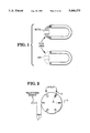
- Metals in general, have a high magnetic permeability, and thus a low reluctance, as compared with air. Thus, for example, if a block of metal is placed within a magnetic field, as in FIG. 1, the flux lines will preferentially pack into the metal as compared with air. Restated, it is "easier" for the magnetic field to create a large number of flux lines within the metal than within the air.
- FIG. 2 illustrates one such sensor 3 located near a slotted wheel 9.
- the reluctance changes. That is, in FIG. 3A, reluctance is 10w, because the sensor "sees” mostly metal (more flux lines can be packed into the metal).
- FIG. 3B reluctance is higher, because the sensor sees the slot, which is mostly air, which has a higher reluctance (fewer field lines can be packed in).
- FIG. 3C reluctance is low again, because of the greater amount of metal near the sensor.
- a signal resembling that shown in FIG. 4A can be derived from the changing reluctance of the rotating slotted wheel.
- the signal has a zero crossing 12, (shown in FIG. 4B) which occurs when the center 13 (or other reference point) in FIG. 2 of the slot passes the probe coil.
- Such a sensor is commonly called a "reluctance sensor.”
- the term "reluctance sensor” is somewhat inaccurate: the signal of FIG. 4A does not directly indicate reluctance. That is, when the zero crossing occurs, reluctance does not actually go to zero; some finite reluctance still exists. Rather, the signal represents a time-derivative of a voltage derived from reluctance. The time-derivative does go to zero, when the reluctance reaches its minimum.
- the change in reluctance seen by the sensor can be used to measure speed and angular position of the slotted wheel.
- numerous factors introduce electrical noise, which tends to obscure the signal.
- the slotted wheel can be connected to a crankshaft in an automotive engine. The engine vibrates. The vibration increases, in both frequency and amplitude, as engine speed increases.
- the vibration induces the probe coil to also vibrate, meaning that the probe coil moves with respect to the slotted wheel: distance D in FIG. 2 periodically changes.
- This change in D changes the signal of FIG. 4A, because the change in D causes its own change in reluctance.
- the noise causes the following problem. At low speeds, the signal produced by the probe coil is small, as indicated in FIG. 4A. At low speeds the noise signals are also small. At high speeds, as in FIG. 4C, both the noise and the probe-coil-signal are large. The problem is designing an apparatus which will detect the reluctance signal at both high and low speeds.
- the threshold must be above or below the noise level. If the threshold is below the noise level, then, at high engine speeds, the noise itself triggers the comparator. On the other hand, if the threshold is above the noise level, then, at low engine speeds, the comparator will not detect the probe coil signals: they are too small.
- the threshold can be adjusted, based on engine speed. In principle, this solution is possible, but requires a separate measuring apparatus for measuring engine speed, which is expensive.
- a reluctance sensor produces reluctance signals in response to passing slots in a rotating wheel.
- a DIG -- OUT signal is produced.
- the signal falls to zero, the DIG -- OUT signal is terminated.
- the invention adjusts the threshold, based on the magnitude of the reluctance signals. Since the magnitude of the reluctance signals depends on wheel speed, the invention, in effect, adjusts the threshold based on wheel speed, yet without independently measuring wheel speed.
- FIG. 1 illustrates how a magnetic field generates more flux lines within a metal than within air.
- FIG. 2 illustrates a reluctance sensor and a slotted wheel.
- FIGS. 3A-3C illustrate a slot passing the reluctance sensor of FIG. 2.
- FIGS. 4A-4C illustrate three types of reluctance signals, produced at three different speeds.
- FIG. 5 is an overview of one form of the invention.
- FIG. 6 illustrates in detail the INPUT FILTER of FIG. 5.
- FIG. 7 illustrates the LIMITER of FIG. 5.
- FIGS. 8A and 8B illustrates how the threshold THRES+ of the SCHMITT TRIGGER in FIG. 5 is repeatedly updated.
- FIG. 9 illustrates the PEAK DETECTOR of FIG. 5.
- FIGS. 9A and 9B illustrate the two alternate states in which the analog switches ANSW1K of FIG. 9 can reside.
- FIG. 10 illustrates the STATE MACHINE of FIG. 5, together with the STATE DIAGRAM which describes the operation of the STATE MACHINE.
- FIGS. 11, 11A and 11B illustrate the LEAKY INTEGRATOR of FIG. 5.
- FIG. 12 illustrates the SCHMITT TRIGGER of FIG. 5.
- FIG. 5 gives an overview of the invention.
- a SCHMITT TRIGGER is triggered by a signal, LS, which is derived from the reluctance signal. The triggering occurs when the signal LS exceeds THRES+, as indicated at the upper right part of the Figure.
- THRES+ is not fixed in value, but increases as engine speed increases. At low speeds, THRES+ is small enough that the small reluctance signals will trip the SCHMITT TRIGGER. At high speeds, THRES+ is large enough that the noise signals do not trip the SCHMITT TRIGGER.
- the adjustment of THRES+ is handled by the combined operation of the blocks labeled PEAK DETECTOR, LEAKY INTEGRATOR, and STATEMACHINE. In brief, the PEAK DETECTOR samples and holds the LS signal, which is large at high speeds and small at low speeds. The STATE MACHINE updates THRES+ with the sampled-and-held value at each falling edge of DIG -- OUT.
- the SCHMITT TRIGGER is reset when the reluctance signal falls to THRES-, as indicated: DIG -- OUT falls to zero at this time.
- THRES- is fixed, preferably at 0.0 volts.
- the incoming reluctance signal is filtered and clamped by blocks INPUT FILTER and LIMITER, respectively, as will be later explained.
- a wheel having six slots can be used, and the DIG -- OUT signal can be used to fire the spark plugs. Because THRES+ changes with engine speed, the reluctance signal at both low and high speeds can be detected, thus allowing DIG -- OUT to control firing of the plugs at both high and low speeds, without independent measurement of speed of the wheel 9.
- FIG. 6 shows the INPUT FILTER.
- Resistors R1 and R2 form a voltage divider, which divide the voltage applied to lines SENSE+ and SENSE- in half.
- the particular values of C1, R1, and R2, form a low-pass filter having a single pole at 15.9 kHz, as indicated in the Figure.
- the low-pass filter suppresses high-frequency noise.
- the INPUT FILTER is implemented using discrete components, primarily because of the relatively large size of C1, namely, 0.1 ⁇ Farad.
- the remaining components in FIG. 5 are implemented on a single integrated circuit.
- FIG. 7 shows the LIMITER of FIG. 5.
- An exemplary reluctance signal is shown at node FS.
- Zener diode D1 clamps the reluctance signal to 6.3 volts, as indicated by waveform 17, and prevents high voltages produced by the reluctance sensor from reaching the downstream components, which node LS feeds. Further, D1 clips the negative part (shown in phantom) of the reluctance signal at a few tenths of a volt.
- D1 provides both clamping (of the positive half-cycles) and half-wave rectification (by blocking, or clipping, the negative half-cycles).
- FIGS. 8A and 8B The PEAK DETECTOR, INTEGRATOR, STATE MACHINE and SCHMITT TRIGGER can be explained by FIGS. 8A and 8B.
- the PEAK DETECTOR is indicated by capacitors C2 and C3, and switches SW1 and SW2.
- the integrator is indicated by capacitor C4.
- the limited reluctance signal, LS from FIG. 7, is fed to both the SCHMITT TRIGGER and FET M1, as shown in the upper left corner of FIG. 8A.
- the system repeatedly passes through a sequence of three states, during which THRES+ is adjusted, based on the amplitude of LS (and thus based on speed of the slotted wheel), as will now be explained.
- the state machine is in state S 0 .
- Switches SW1 in the upper left part of FIG. 8A are closed, and LS is charging capacitor C2, as indicated by the dashed path 19.
- Capacitor C3 is grounded.
- the STATE MACHINE switches into state S 2 .
- This state causes switches SW1 to open, and SW2 to close, as indicated in the circuit labeled S2, located at the lower left.
- C2 and C3 are connected in parallel, with each other and with C4.
- connection of C2 with C3 causes the voltage originally on C2 to be cut in half: C2 and C3 are equal in value, but C3 carried no charge, because it was previous grounded. Connecting them together divided the voltage initially on C2 in half. Then, the charge shared by C2 and C3 is applied to C4. C4 may or may not have a pre-existing voltage at this time.
- a 20-pF capacitor (C2-plus-C3) having a charge Q 20 and voltage V 20 is connected in parallel with a 50-pF capacitor (C4) having an initial charge Q 50 and voltage V 50 , both of which are possibly zero.
- V 50 V 20
- C 20 Q 20 /V 20
- C 50 Q 50 /V 50 .
- C4 since C4 (ie, C 50 in the preceding equations) has a value of 50 pF, which is 2.5 times large than the combined value of C2-plus-C3 (ie, C 20 or 20 pF), C4 does not attain the full voltage of C2.
- all of the voltage on C2 (which is indicative of the size of the LS signal) is initially applied to C4, however, when SW2 is closed, the total charge in C2 is redistributed between C2 and C4, resulting in a lower voltage across C4. Since C4 has a higher capacitance than C2 (50 pF and 20 pF, respectively) and Q remains constant, then voltage across C4 must necessarily drop in accordance with the above equation.
- THRES+ is incrementally driven to the voltage of C2, and is not changed abruptly.
- State S 2 lasts for a single clock cycle. At the next clock cycle, the STATE MACHINE switches into state S 0 , and the process repeats.
- the individual components will now be considered in more detail.
- the limited reluctance signal, LS is fed to node LS of the PEAK DETECTOR.
- a diode effect is present at this node, for two reasons.
- the signal has already been half-wave rectified, by the LIMITER, as discussed above.
- M1 is a field-effect device. That is, when the signal at node LS goes HIGH, M1 is triggered into conduction. However, when the signal goes LOW, M1 is turned off. Therefore, M1 passes current only when node FS is above the threshold voltage, V T , of M1. M1, in this respect, resembles a diode.
- C2 acquires a voltage indicative of the limited signal LS.
- the PEAK DETECTOR can be viewed as residing in one of two possible states.
- the first state is shown in FIG. 9A. This state persists so long as the XFER line is LOW. (XFER is controlled by the STATE MACHINE.)
- the signal on line LS (also shown in FIG. 9) delivers a current through M1 and charges capacitor C2.
- C2 acquires a voltage indicative of the magnitude of signal LS, which is the Limited Reluctance signal.
- the second significant event is that capacitor C3 is grounded, and thereby held at zero volts.
- the second state is caused by a HiGH signal on line XFER.
- capacitors C2 and C3 are disconnected from their respective inputs, namely, LS and ground, and both are then connected to a common output, PEAK -- OUT.
- capacitors C2, C3, and C4 are all connected in parallel, and acquire the same voltage. If C4 is initially at zero volts, and signal LS is constant, C4 will charge to approximately the voltage of LS after a few switching cycles of SW1 and SW2. Switches SW1 and SW2 take the form of analog switches, known in the art, and are labeled ANSW1K in FIG. 9.
- FIG. 10 shows the STATE MACHINE of FIG. 5.
- the circuitry of the STATE MACHINE is self-explanatory. (Details concerning the design and operation of simple state machines can be found in chapter 4 of COMPUTER ENGINEERING, Hardware Design, by Morris Mano (Prentice Hall, 1988, ISBN 0-13-162926-3). This book is incorporated by reference.) As the STATE DIAGRAM indicates, the STATE MACHINE traverses through three states, which will now be explained.
- the STATE MACHINE There are two state variables in the STATE MACHINE, namely, A and B, as indicated, produced by D-type flip-flops labeled DFFRP. There are two inputs namely, DIG -- OUT and a CLOCK, as indicated.
- Variable A (ie, an output of flip-flop 37) serves as the signal XFER in FIG. 8A.
- XFER attains a value of ONE
- the analog switches SW1 and SW2 in FIG. 9A and 9B switch into the second state, shown in FIG. 9B, thereby connecting the capacitors C2, C3, and C4 together.
- the connection updates the value of THRES+: part of the voltage initially present on C2 is applied to C4, which applies THRE+ to the SCHMITT TRIGGER, as discussed above.
- the STATE MACHINE returns to state S 0 , and the cycle repeats.
- the STATE MACHINE detects each zero-crossing of the LS signal, and modifies THRES+ in accordance with the voltage on C2, at this time. Since the voltage on C2 depends on the size of the reluctance signal, which depends on speed of the slotted wheel, THRES+, in effect, is modified by wheel speed. At high wheel speeds, THRES+ is larger; at low speeds, THRES+ is smaller.
- a single signal, FS performs a three-fold task.
- the timing of LS causes the zero-crossing of DIG -- OUT.
- the amplitude of LS modifies THRES+.
- LS by triggering DIG -- OUT causes the STATE MACHINE to cycle through its sequences.
- the STATE MACHINE operates to detect the zero-crossing of the LS signal.
- Other approaches to detecting the zero crossing can be undertaken, such as differentiation and other types of threshold comparison.
- switches SW4 and SW5 alternate between the states shown in FIGS. 11A and 11B.
- the alternation is caused by the clock pulses CLK, which are indicated in FIG. 8.
- CLK clock pulses
- a small amount of charge is repeatedly drained from C4 by the small (2 pF) capacitor C5, and dumped to ground.
- This repeated draining has the effect of a large resistor, such as phantom resistor 37 in FIG. 11, connected in parallel with C4:C4 will eventually lose its charge, if not re-charged.
- the apparatus in dashed block 39 in FIG. 11 keeps C4 charged to a minimum voltage: when the voltage on C4 falls below MIN -- THRES+, comparator 41 turns on FET M2, and applies a current to C4, charging C4 up to MIN -- THRES+. Thus, a minimum THRES+ is maintained. This minimum is below the peak voltage of the smallest reluctance signal expected.
- C4 can retain a high voltage, placing THRES+ above the noise level. With such a high THRES+, the small reluctance signals produced during engine cranking (ie, a low-speed condition) will not be detected, and the spark plugs will not be fired. The engine will not start.
- FIG. 12 illustrates the SCHMITT TRIGGER.
- Two comparators 44 and 46 compare the limited reluctance signal, LS, with THRES+ and THRES-, respectively.
- the comparators feed the inputs of an R-S flip flop, taking the form of Cross-Coupled Nor Gates (CCNR), which produces DIG -- OUT.
- CCNR Cross-Coupled Nor Gates
Abstract
Description
Claims (5)
Priority Applications (1)
| Application Number | Priority Date | Filing Date | Title |
|---|---|---|---|
| US07/961,974 US5446375A (en) | 1992-10-16 | 1992-10-16 | Reluctance sensor having variable threshold detection circuit |
Applications Claiming Priority (1)
| Application Number | Priority Date | Filing Date | Title |
|---|---|---|---|
| US07/961,974 US5446375A (en) | 1992-10-16 | 1992-10-16 | Reluctance sensor having variable threshold detection circuit |
Publications (1)
| Publication Number | Publication Date |
|---|---|
| US5446375A true US5446375A (en) | 1995-08-29 |
Family
ID=25505257
Family Applications (1)
| Application Number | Title | Priority Date | Filing Date |
|---|---|---|---|
| US07/961,974 Expired - Lifetime US5446375A (en) | 1992-10-16 | 1992-10-16 | Reluctance sensor having variable threshold detection circuit |
Country Status (1)
| Country | Link |
|---|---|
| US (1) | US5446375A (en) |
Cited By (18)
| Publication number | Priority date | Publication date | Assignee | Title |
|---|---|---|---|---|
| US5606274A (en) * | 1994-08-08 | 1997-02-25 | Yozan Inc. | Sampling and holding circuit |
| US5606257A (en) * | 1993-02-04 | 1997-02-25 | Robert Bosch Gmbh | Device for forming a square-wave signal and detecting a reference mark from a sinusoidal signal with a singularity |
| US5777465A (en) * | 1996-02-16 | 1998-07-07 | Analog Devices, Inc. | Circuitry and method for sensing spatial transitions sensed with a magnetic sensor |
| US5812429A (en) * | 1994-06-23 | 1998-09-22 | Delco Electronics Corp. | Adaptive digital filter for automotive applications |
| US5986450A (en) * | 1997-04-04 | 1999-11-16 | Analog Devices | Directionally independent magnet sensor |
| US6064199A (en) * | 1998-02-23 | 2000-05-16 | Analog Devices, Inc. | Magnetic field change detection circuitry having threshold establishing circuitry |
| EP1111392A1 (en) * | 1999-12-20 | 2001-06-27 | Micronas GmbH | Realizing speed and angle position of a rotating wheel with adaptable switching threshold for drift compensation |
| US6429658B1 (en) | 1998-10-05 | 2002-08-06 | Jeffrey E. Thomsen | Engine ignition timing device |
| EP1361416A2 (en) * | 2002-05-08 | 2003-11-12 | Matsushita Electric Industrial Co., Ltd. | Magnetic position detecting device |
| US20030210035A1 (en) * | 2002-05-09 | 2003-11-13 | Manlove Gregory J. | Variable attenuation circuit for a differential variable reluctance sensor with enhanced initial threshold accuracy |
| WO2003104822A1 (en) * | 2002-06-11 | 2003-12-18 | Honeywell International Inc. | Speed sensing system with automatic sensitivity adjustment |
| US20050024006A1 (en) * | 2002-11-06 | 2005-02-03 | Lothar Blossfeld | Device and method for detecting an angular position of a rotating object |
| US20060119348A1 (en) * | 2000-12-20 | 2006-06-08 | Lothar Blossfeld | Technique for sensing the rotational speed and angular position of a rotating wheel using a variable threshold |
| US20100231202A1 (en) * | 2009-03-10 | 2010-09-16 | Scheller P Karl | Magnetic field detector having a variable threshold |
| US9638548B2 (en) | 2012-05-07 | 2017-05-02 | Infineon Technologies Ag | Output switching systems and methods for magnetic field sensors |
| US10102992B2 (en) | 2014-02-25 | 2018-10-16 | Infineon Technologies Ag | Switching apparatus, switching system and switching method |
| US11378585B2 (en) * | 2018-02-09 | 2022-07-05 | Knorr-Bremse Systeme Fuer Nutzfahrzeuge Gmbh | Method and device for determining a speed by means of an inductive speed sensor |
| EP4312378A1 (en) * | 2022-07-28 | 2024-01-31 | STMicroelectronics S.r.l. | Threshold voltage generator circuit and corresponding receiver device |
Citations (16)
| Publication number | Priority date | Publication date | Assignee | Title |
|---|---|---|---|---|
| US3094665A (en) * | 1959-04-27 | 1963-06-18 | Raytheon Co | Means for the detection of signals in the presence of noise |
| US4121112A (en) * | 1975-07-02 | 1978-10-17 | Gunter Fritz Hartig | Pulse generator |
| US4175256A (en) * | 1976-07-30 | 1979-11-20 | Motorola, Inc. | Dynamic threshold tone detector |
| US4258324A (en) * | 1977-08-29 | 1981-03-24 | The Bendix Corporation | Signal conditioning circuit for magnetic sensing means |
| US4293814A (en) * | 1979-08-08 | 1981-10-06 | Ford Motor Company | Crankshaft position sensor circuitry for providing stable cyclical output signals without regard to peak to peak variations in sensor signals |
| US4367721A (en) * | 1979-08-08 | 1983-01-11 | Ford Motor Company | Signal detection circuit with self-adjusting threshold having modulated carrier input |
| US4575677A (en) * | 1984-05-25 | 1986-03-11 | Mobil Oil Corporation | Motor speed detector |
| US4609990A (en) * | 1984-08-06 | 1986-09-02 | General Electric Company | Frequency measurement system |
| US4635142A (en) * | 1983-11-22 | 1987-01-06 | Storage Technology Corporation | Amplitude sensor with adaptive threshold generation |
| US4836616A (en) * | 1986-01-31 | 1989-06-06 | Rockwell International Corporation | Antilock brake system |
| US4914387A (en) * | 1988-04-04 | 1990-04-03 | The Torrington Company | Magnetic speed sensor with an adaptive threshold circuit for use with a bearing assembly |
| US5012207A (en) * | 1988-10-06 | 1991-04-30 | Lucas Industries Public Limited Company | Variable reluctance transducer processing circuit for providing an output unaffected by low frequency components |
| US5015879A (en) * | 1988-10-25 | 1991-05-14 | Marelli Autronica S.P.A. | Circuit for processing the signal generated by a variable-reluctance electromagnetic rotation sensor |
| US5029286A (en) * | 1986-11-22 | 1991-07-02 | Robert Bosch Gmbh | Pulse shaper for inductive pickups having a voltage controlled differential voltage divider |
| US5144233A (en) * | 1991-08-30 | 1992-09-01 | Delco Electronics Corporation | Crankshaft angular position voltage developing apparatus having adaptive control and diode control |
| US5221250A (en) * | 1991-01-07 | 1993-06-22 | Beckman Instruments, Inc. | Coding of maximum operating speed on centrifuge rotors and detection thereof |
-
1992
- 1992-10-16 US US07/961,974 patent/US5446375A/en not_active Expired - Lifetime
Patent Citations (16)
| Publication number | Priority date | Publication date | Assignee | Title |
|---|---|---|---|---|
| US3094665A (en) * | 1959-04-27 | 1963-06-18 | Raytheon Co | Means for the detection of signals in the presence of noise |
| US4121112A (en) * | 1975-07-02 | 1978-10-17 | Gunter Fritz Hartig | Pulse generator |
| US4175256A (en) * | 1976-07-30 | 1979-11-20 | Motorola, Inc. | Dynamic threshold tone detector |
| US4258324A (en) * | 1977-08-29 | 1981-03-24 | The Bendix Corporation | Signal conditioning circuit for magnetic sensing means |
| US4293814A (en) * | 1979-08-08 | 1981-10-06 | Ford Motor Company | Crankshaft position sensor circuitry for providing stable cyclical output signals without regard to peak to peak variations in sensor signals |
| US4367721A (en) * | 1979-08-08 | 1983-01-11 | Ford Motor Company | Signal detection circuit with self-adjusting threshold having modulated carrier input |
| US4635142A (en) * | 1983-11-22 | 1987-01-06 | Storage Technology Corporation | Amplitude sensor with adaptive threshold generation |
| US4575677A (en) * | 1984-05-25 | 1986-03-11 | Mobil Oil Corporation | Motor speed detector |
| US4609990A (en) * | 1984-08-06 | 1986-09-02 | General Electric Company | Frequency measurement system |
| US4836616A (en) * | 1986-01-31 | 1989-06-06 | Rockwell International Corporation | Antilock brake system |
| US5029286A (en) * | 1986-11-22 | 1991-07-02 | Robert Bosch Gmbh | Pulse shaper for inductive pickups having a voltage controlled differential voltage divider |
| US4914387A (en) * | 1988-04-04 | 1990-04-03 | The Torrington Company | Magnetic speed sensor with an adaptive threshold circuit for use with a bearing assembly |
| US5012207A (en) * | 1988-10-06 | 1991-04-30 | Lucas Industries Public Limited Company | Variable reluctance transducer processing circuit for providing an output unaffected by low frequency components |
| US5015879A (en) * | 1988-10-25 | 1991-05-14 | Marelli Autronica S.P.A. | Circuit for processing the signal generated by a variable-reluctance electromagnetic rotation sensor |
| US5221250A (en) * | 1991-01-07 | 1993-06-22 | Beckman Instruments, Inc. | Coding of maximum operating speed on centrifuge rotors and detection thereof |
| US5144233A (en) * | 1991-08-30 | 1992-09-01 | Delco Electronics Corporation | Crankshaft angular position voltage developing apparatus having adaptive control and diode control |
Cited By (30)
| Publication number | Priority date | Publication date | Assignee | Title |
|---|---|---|---|---|
| US5606257A (en) * | 1993-02-04 | 1997-02-25 | Robert Bosch Gmbh | Device for forming a square-wave signal and detecting a reference mark from a sinusoidal signal with a singularity |
| US5812429A (en) * | 1994-06-23 | 1998-09-22 | Delco Electronics Corp. | Adaptive digital filter for automotive applications |
| US5606274A (en) * | 1994-08-08 | 1997-02-25 | Yozan Inc. | Sampling and holding circuit |
| US5777465A (en) * | 1996-02-16 | 1998-07-07 | Analog Devices, Inc. | Circuitry and method for sensing spatial transitions sensed with a magnetic sensor |
| US5986450A (en) * | 1997-04-04 | 1999-11-16 | Analog Devices | Directionally independent magnet sensor |
| US6064199A (en) * | 1998-02-23 | 2000-05-16 | Analog Devices, Inc. | Magnetic field change detection circuitry having threshold establishing circuitry |
| US6429658B1 (en) | 1998-10-05 | 2002-08-06 | Jeffrey E. Thomsen | Engine ignition timing device |
| US20040189306A1 (en) * | 1998-10-05 | 2004-09-30 | Thomsen Jeffrey E. | Sensor for ignition timing device |
| US7023214B2 (en) | 1998-10-05 | 2006-04-04 | Jeffrey E. Thomsen | Sensor for ignition timing device |
| US6664789B2 (en) | 1998-10-05 | 2003-12-16 | Jeffrey E. Thomsen | Engine ignition timing device |
| EP1111392A1 (en) * | 1999-12-20 | 2001-06-27 | Micronas GmbH | Realizing speed and angle position of a rotating wheel with adaptable switching threshold for drift compensation |
| US20010013775A1 (en) * | 1999-12-20 | 2001-08-16 | Lothar Blossfeld | Technique for sensing the rotational speed and angular position of a rotating wheel |
| US6965227B2 (en) * | 1999-12-20 | 2005-11-15 | Micronas Gmbh | Technique for sensing the rotational speed and angular position of a rotating wheel using a variable threshold |
| US20060119348A1 (en) * | 2000-12-20 | 2006-06-08 | Lothar Blossfeld | Technique for sensing the rotational speed and angular position of a rotating wheel using a variable threshold |
| US7262591B2 (en) | 2000-12-20 | 2007-08-28 | Micronas Gmbh | Technique for sensing the rotational speed and angular position of a rotating wheel |
| EP1361416A3 (en) * | 2002-05-08 | 2005-07-13 | Matsushita Electric Industrial Co., Ltd. | Magnetic position detecting device |
| EP1361416A2 (en) * | 2002-05-08 | 2003-11-12 | Matsushita Electric Industrial Co., Ltd. | Magnetic position detecting device |
| US6674279B2 (en) * | 2002-05-09 | 2004-01-06 | Delphi Technologies, Inc. | Variable attenuation circuit for a differential variable reluctance sensor with enhanced initial threshold accuracy |
| US20030210035A1 (en) * | 2002-05-09 | 2003-11-13 | Manlove Gregory J. | Variable attenuation circuit for a differential variable reluctance sensor with enhanced initial threshold accuracy |
| US6798192B2 (en) * | 2002-06-11 | 2004-09-28 | Honeywell International, Inc. | Speed sensing system with automatic sensitivity adjustment |
| WO2003104822A1 (en) * | 2002-06-11 | 2003-12-18 | Honeywell International Inc. | Speed sensing system with automatic sensitivity adjustment |
| US20030231013A1 (en) * | 2002-06-11 | 2003-12-18 | Honeywell International, Inc., Law Dept. Ab2 | Speed sensing system with automatic sensitivity adjustment |
| US7369960B2 (en) | 2002-11-06 | 2008-05-06 | Micronas Gmbh | Device and method for detecting an angular position of a rotating object |
| US20050024006A1 (en) * | 2002-11-06 | 2005-02-03 | Lothar Blossfeld | Device and method for detecting an angular position of a rotating object |
| US20100231202A1 (en) * | 2009-03-10 | 2010-09-16 | Scheller P Karl | Magnetic field detector having a variable threshold |
| US8089270B2 (en) * | 2009-03-10 | 2012-01-03 | Allegro Microsystems, Inc. | Magnetic field detector having a variable threshold |
| US9638548B2 (en) | 2012-05-07 | 2017-05-02 | Infineon Technologies Ag | Output switching systems and methods for magnetic field sensors |
| US10102992B2 (en) | 2014-02-25 | 2018-10-16 | Infineon Technologies Ag | Switching apparatus, switching system and switching method |
| US11378585B2 (en) * | 2018-02-09 | 2022-07-05 | Knorr-Bremse Systeme Fuer Nutzfahrzeuge Gmbh | Method and device for determining a speed by means of an inductive speed sensor |
| EP4312378A1 (en) * | 2022-07-28 | 2024-01-31 | STMicroelectronics S.r.l. | Threshold voltage generator circuit and corresponding receiver device |
Similar Documents
| Publication | Publication Date | Title |
|---|---|---|
| US5446375A (en) | Reluctance sensor having variable threshold detection circuit | |
| JP2746698B2 (en) | Circuit device for processing signals generated by a variable reluctance electromagnetic rotation sensor | |
| JP6271179B2 (en) | Variable magnetoresistive sensor interface and method using integral based arming threshold | |
| US4333334A (en) | Knocking discrimination apparatus | |
| US7049859B2 (en) | Variable threshold comparator interface circuit | |
| JP6452217B2 (en) | VRS interface using 1 / T arming function | |
| EP0668505B1 (en) | Dual comparator trigger circuit for glitch capture | |
| GB2047027A (en) | Commutatorless direct current motor drive system | |
| US5343843A (en) | Knock control for high speed engine including a knock burst envelope follower | |
| US5015879A (en) | Circuit for processing the signal generated by a variable-reluctance electromagnetic rotation sensor | |
| SE439565B (en) | SAMPLING FILTER DETECTOR | |
| US4085373A (en) | Frequency-to-voltage transducer for speed governor systems or the like | |
| US4727270A (en) | Noise immune circuit for use with frequency sensor | |
| EP0516687B1 (en) | Signal conditioning circuit | |
| JP2583652B2 (en) | Rotation angle detector | |
| EP0973258A2 (en) | Threshold crossing discrimination for oscillatory signals | |
| US4754438A (en) | Geophone testing apparatus | |
| US9176159B2 (en) | Variable reluctance sensor interfaces with signal pre-processing and methods of their operation | |
| US5796232A (en) | Circuit configuration for the evaluation of sensor signals of inductive sensors in motor vehicles | |
| JPS6311870A (en) | Impact-coefficient measuring device for pulse, frequency of which change | |
| US4329970A (en) | Engine spark timing control with added retard and RF signal protection | |
| JPH0629818A (en) | Proximity switch | |
| EP0039993A2 (en) | Internal combustion engines having knock control | |
| US4088901A (en) | Circuit for recognizing a pulse waveform and an ignition system for an i.c. engine including such a circuit | |
| SU178409A1 (en) |
Legal Events
| Date | Code | Title | Description |
|---|---|---|---|
| AS | Assignment |
Owner name: NCR CORPORATION, OHIO Free format text: ASSIGNMENT OF ASSIGNORS INTEREST;ASSIGNOR:PERKINS, LUKE A.;REEL/FRAME:006560/0681 Effective date: 19921002 |
|
| AS | Assignment |
Owner name: HYUNDAI ELECTRONICS AMERICA Free format text: ASSIGNMENT OF ASSIGNORS INTEREST;ASSIGNOR:AT&T GLOBAL INFORMATION SOLUTIONS COMPANY (FORMERLY KNOWN AS NCR CORPORATION);REEL/FRAME:007408/0104 Effective date: 19950215 |
|
| STCF | Information on status: patent grant |
Free format text: PATENTED CASE |
|
| AS | Assignment |
Owner name: SYMBIOS LOGIC INC., COLORADO Free format text: ASSIGNMENT OF ASSIGNORS INTEREST;ASSIGNOR:HYUNDAI ELECTRONICS AMERICA;REEL/FRAME:007629/0431 Effective date: 19950818 |
|
| CC | Certificate of correction | ||
| FEPP | Fee payment procedure |
Free format text: PAYOR NUMBER ASSIGNED (ORIGINAL EVENT CODE: ASPN); ENTITY STATUS OF PATENT OWNER: LARGE ENTITY |
|
| AS | Assignment |
Owner name: SYMBIOS, INC ., COLORADO Free format text: CHANGE OF NAME;ASSIGNOR:SYMBIOS LOGIC INC.;REEL/FRAME:009089/0936 Effective date: 19971210 |
|
| AS | Assignment |
Owner name: LEHMAN COMMERCIAL PAPER INC., AS ADMINISTRATIVE AG Free format text: SECURITY AGREEMENT;ASSIGNORS:HYUNDAI ELECTRONICS AMERICA, A CORP. OF CALIFORNIA;SYMBIOS, INC., A CORP. OF DELAWARE;REEL/FRAME:009396/0441 Effective date: 19980226 |
|
| AS | Assignment |
Owner name: HYUNDAI ELECTRONICS AMERICA, CALIFORNIA Free format text: TERMINATION AND LICENSE AGREEMENT;ASSIGNOR:SYMBIOS, INC.;REEL/FRAME:009596/0539 Effective date: 19980806 |
|
| FPAY | Fee payment |
Year of fee payment: 4 |
|
| REMI | Maintenance fee reminder mailed | ||
| FPAY | Fee payment |
Year of fee payment: 8 |
|
| AS | Assignment |
Owner name: HYNIX SEMICONDUCTOR AMERICA INC., CALIFORNIA Free format text: CHANGE OF NAME;ASSIGNOR:HYUNDAI ELECTRONICS AMERICA;REEL/FRAME:015246/0599 Effective date: 20010412 |
|
| AS | Assignment |
Owner name: MAGNACHIP SEMICONDUCTOR, LTD., KOREA, REPUBLIC OF Free format text: ASSIGNMENT OF ASSIGNORS INTEREST;ASSIGNOR:HYNIX SEMICONDUCTOR, INC.;REEL/FRAME:016216/0649 Effective date: 20041004 |
|
| AS | Assignment |
Owner name: U.S. BANK NATIONAL ASSOCIATION, AS COLLATERAL TRUS Free format text: SECURITY INTEREST;ASSIGNOR:MAGNACHIP SEMICONDUCTOR, LTD.;REEL/FRAME:016470/0530 Effective date: 20041223 |
|
| AS | Assignment |
Owner name: SYMBIOS, INC., COLORADO Free format text: RELEASE OF SECURITY INTEREST;ASSIGNOR:LEHMAN COMMERICAL PAPER INC.;REEL/FRAME:016602/0895 Effective date: 20050107 Owner name: HYUNDAI ELECTRONICS AMERICA, CALIFORNIA Free format text: RELEASE OF SECURITY INTEREST;ASSIGNOR:LEHMAN COMMERICAL PAPER INC.;REEL/FRAME:016602/0895 Effective date: 20050107 |
|
| FPAY | Fee payment |
Year of fee payment: 12 |
|
| AS | Assignment |
Owner name: TAIWAN SEMICONDUCTOR MANUFACTURING CO., LTD., TAIW Free format text: ASSIGNMENT OF ASSIGNORS INTEREST;ASSIGNORS:NCR CORPORATION;MAGNACHIP SEMICONDUCTOR, LTD.;REEL/FRAME:021398/0702;SIGNING DATES FROM 20071114 TO 20071115 |