US5440909A - Lock and key shell assembly - Google Patents
Lock and key shell assembly Download PDFInfo
- Publication number
- US5440909A US5440909A US08/084,416 US8441693A US5440909A US 5440909 A US5440909 A US 5440909A US 8441693 A US8441693 A US 8441693A US 5440909 A US5440909 A US 5440909A
- Authority
- US
- United States
- Prior art keywords
- lock
- grip portion
- key
- annular surface
- piston
- Prior art date
- Legal status (The legal status is an assumption and is not a legal conclusion. Google has not performed a legal analysis and makes no representation as to the accuracy of the status listed.)
- Expired - Fee Related
Links
Images


Classifications
-
- E—FIXED CONSTRUCTIONS
- E05—LOCKS; KEYS; WINDOW OR DOOR FITTINGS; SAFES
- E05B—LOCKS; ACCESSORIES THEREFOR; HANDCUFFS
- E05B63/00—Locks or fastenings with special structural characteristics
- E05B63/12—Locks or fastenings with special structural characteristics with means carried by the bolt for interlocking with the keeper
- E05B63/121—Locks or fastenings with special structural characteristics with means carried by the bolt for interlocking with the keeper using balls or the like cooperating with notches
-
- E—FIXED CONSTRUCTIONS
- E05—LOCKS; KEYS; WINDOW OR DOOR FITTINGS; SAFES
- E05B—LOCKS; ACCESSORIES THEREFOR; HANDCUFFS
- E05B19/00—Keys; Accessories therefor
-
- Y—GENERAL TAGGING OF NEW TECHNOLOGICAL DEVELOPMENTS; GENERAL TAGGING OF CROSS-SECTIONAL TECHNOLOGIES SPANNING OVER SEVERAL SECTIONS OF THE IPC; TECHNICAL SUBJECTS COVERED BY FORMER USPC CROSS-REFERENCE ART COLLECTIONS [XRACs] AND DIGESTS
- Y10—TECHNICAL SUBJECTS COVERED BY FORMER USPC
- Y10T—TECHNICAL SUBJECTS COVERED BY FORMER US CLASSIFICATION
- Y10T70/00—Locks
- Y10T70/70—Operating mechanism
- Y10T70/7441—Key
- Y10T70/778—Operating elements
- Y10T70/7791—Keys
- Y10T70/7802—Multi-part structures
- Y10T70/7814—With extensible shank or stem
-
- Y—GENERAL TAGGING OF NEW TECHNOLOGICAL DEVELOPMENTS; GENERAL TAGGING OF CROSS-SECTIONAL TECHNOLOGIES SPANNING OVER SEVERAL SECTIONS OF THE IPC; TECHNICAL SUBJECTS COVERED BY FORMER USPC CROSS-REFERENCE ART COLLECTIONS [XRACs] AND DIGESTS
- Y10—TECHNICAL SUBJECTS COVERED BY FORMER USPC
- Y10T—TECHNICAL SUBJECTS COVERED BY FORMER US CLASSIFICATION
- Y10T70/00—Locks
- Y10T70/70—Operating mechanism
- Y10T70/7441—Key
- Y10T70/778—Operating elements
- Y10T70/7791—Keys
- Y10T70/7876—Bow or head
Definitions
- This invention relates to locking assemblies and is directed more particularly to a cylinder-type lock assembly and a key shell assembly for use therewith, the key shell assembly being operable to prevent rotation of a body portion of the lock assembly upon turning of the cylinder portion of the lock assembly in the body portion.
- a lock assembly including a tubular lock body and disposed therein a cylinder adapted to be turned by a key inserted in a key way in the cylinder.
- the cylinder turns through a limited arc in the lock body to activate a lock mechanism and the lock body remains stationary. It is sometimes the case that the lock body is loosely mounted in its base member and, upon turning of the cylinder, there is concurrent turning of the lock body, such that no relative turning takes place between the cylinder and the lock body and the lock assembly fails to function.
- An object of the invention is, therefore, to provide a lock and key assembly wherein the key assembly is operative to engage a lock body portion of a lock assembly and retain the body portion against rotative movement, while the key is manipulable to rotate a lock cylinder portion within the lock body portion to effect relative rotative movement therebetween, to effect activation of a lock mechanism.
- a feature of the present invention is the provision of a lock and key shell assembly comprising a lock assembly for securing a first member to a second member, the lock assembly comprising a lock body having a first cylindrical portion for disposal in a first bore in the first member and a first bore in the second member, a second cylindrical portion for disposal in a second bore in the second member, the second cylindrical portion having a larger diameter than the first cylindrical portion and having an exposed annular surface, an annular collar portion extending outwardly from the first cylindrical portion and forming an end of the second cylindrical portion, a cylinder mounted for rotative movement in the lock body, the cylinder having a head portion disposed in the lock body second cylindrical portion and having a keyway therein and a shank portion extending from the head portion and disposed in the lock body first cylindrical portion, movable members mounted in openings in the first cylindrical portion and adapted to enter recesses in the first member to lock the lock assembly first cylindrical portion to the first member
- FIG. 1 is an elevational, partly sectional, view of a prior art lock and key assembly
- FIG. 2 is an elevational, partly sectional, view of one form of a lock and key shell assembly illustrative of an embodiment of the invention
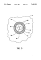
- FIG. 3 is a top plan view of the lock assembly, taken along line III--III of FIG. 2;
- FIG. 4 is an elevational, partly sectional, view of another form of lock and key shell assembly illustrative of an alternative embodiment of the invention.
- FIG. 5 is an elevational, partly sectional, view of another form of lock and key shell assembly illustrative of another alternative embodiment of the invention.
- FIG. 6 is an elevational, partly sectional, view of still another form of key shell assembly illustrative of another alternative embodiment of the invention.
- the lock assembly 6 includes a lock body 8.
- the lock body 8 is provided with a first cylindrical portion 10 adapted to be disposed in a first bore 12 in the first member 2 and a first bore 14 in the second member 4.
- the lock body 8 is further provided with a second cylindrical portion 16 adapted to be disposed in a second bore 18 in the second member 4.
- the first and second members first bores 12, 14 are substantially equal in diameter.
- the diameter of the second bore 18 is larger than the diameters of the first bores 12, 14.
- An annular collar portion 20 extends radially outwardly from the first cylindrical portion 10 and forms an end of the second cylindrical portion 16.
- a shelf 22 in the second bore 18 receives the collar portion 20 of the second cylindrical portion 16 and is in abutting engagement therewith.
- the lock and key assembly includes a cylinder 30 mounted for rotative movement in the lock body 8.
- the cylinder 30 is provided with a head portion 32 disposed in the lock body second cylindrical portion 16 and having a keyway 34 therein adapted to receive a key K, and a shank portion 36 integral with, and extending from, the head portion 32.
- the lock mechanism of the lock assembly 6 includes the provision in the shank portion 36 of the cylinder 30 near its distal end, of flat portions 38 and rounded portions 40.
- the lock body first cylindrical portion 10 is provided with openings 42 in which are disposed balls 44.
- the openings 42 are aligned with recesses 46 in the first member 2.
- the rounded portions 40 of the cylinder shank portion 36 when engaged with the balls 44, force the balls 44 in part into the first member recesses 46, preventing the withdrawal of the lock assembly from the first member first bore 12, thereby preventing separation of the first and second members 2,4.
- the balls are accommodated by the openings 42, permitting withdrawal of the lock body 8 and cylinder 30 from the first member 2, and thereby permitting separation of the first and second members 2,4.
- a pin 48 extends inwardly from the lock body second cylindrical portion 16, with a distal end thereof disposed in a closed end groove 50 in a side wall of the cylinder 30.
- the closed end groove 50 serves to limit movement of the groove about the pin 48 and thereby limit rotational movement of the cylinder 30 in the lock body 8.
- the lock and key assembly of the present invention includes a key shell assembly comprising tubular grip portion 60, a piston 62 slidably disposed in the grip portion, and a key shank 64 extending from one end of the piston 62 and adapted to enter the keyway 34.
- the grip portion is provided with first and second edges 66,68.
- the piston 62 is slidably movable axially in the grip portion 60 to move the key shank 64 into and out of engagement with the keyway 34, and is movable rotatively in the grip portion 60 to effect turning of the key shank 64.
- the piston 62 may be provided with a cap portion 70 adapted to engage the grip portion second edge 68 to limit axial movement of the piston 62 in the grip portion 60.
- the lock body second cylindrical portion 16, on an upper annular edge 80 thereof, is provided with a toothed surface 82 which is complementary to a toothed surface 84 on the grip portion first edge 66.
- the complementary surfaces 82, 84 need not be “toothed” in a literal sense, but do have surfaces which are interlocking, such that the lock body 8 is held against turning movement relative to the key assembly grip portion 60.
- the key shank 64 is shown in FIG. 2 as a shank portion of an ordinary tumbler-type padlock key or door key, similar to the key K shown in FIG. 1, but the key shank 64 may, in practice, be a generally cylindrical shank with appropriate cam surfaces formed therein, or other such extension capable of entering a keyway and activating a lock in which the keyway is disposed.
- FIG. 4 there is shown an alternative embodiment in which the lock body second cylindrical portion upper annular edge 80 remains substantially planar and the first edge 66 of the key shell tubular grip portion 60 has fixed thereto a friction ring 90, of rubber or the like, adapted to engage the lock body edge 80.
- the friction ring 90 may be a complete ring or, alternatively, segments thereof.
- the annular edge 80 may be roughened, stepped, or otherwise configured to provide additional frictional properties.
- FIG. 5 there is shown another alternative embodiment in which the lock body second cylindrical portion 16 is provided with an extended wall portion 92 which extends beyond a surface 94 of the second member 4.
- the lock body edge 80 comprises a generally frusto-conical surface 96.
- the tubular grip portion first edge 66 is configured complementarily to the surface 96 and adapted to engage the surface 96.
- the frusto-conical surfaces 66, 96 may be textured or otherwise configured to increase frictional properties.
- FIG. 6 there is shown another alternative embodiment in which the piston 62 is axially fixed in the grip portion 60, but rotatably moveable therein.
- the first edge 66 of the grip portion 60 may be of the type shown in any of FIGS. 2-5.
- the piston 62 is stationary axially of the grip portion 60 and is not axially moveable therein, contrary to the other embodiments illustrated.
- an operator grasps the tubular grip portion 60 with the piston 62 therein.
- the first edge 66 of the grip portion 60 is brought to bear against the lock body edge 80.
- the key shell toothed surface 84 is brought into engagement with the lock body toothed surface 82.
- the friction ring 90 is brought into engagement with the lock body edge 80.
- the key shell frusto-conically shaped surface 66 is brought into engagement with the lock body frusto-conically shaped surface 96.
- the operator then pushes the piston 62 axially into the grip portion 60, causing the key shank 64 to enter the keyway 34.
- the key shank 64 enters the keyway 34 as the edges 66, 80 are brought together.
- the operator using the cap portion 70, turns the piston 62 in the grip portion 60, causing the key shank 64 to activate the lock mechanism.
- the engagement of the grip portion with the lock body serves to hold the lock body against rotation while the key shank 64, and thereby the cylinder 30, is turned.
Abstract
Description
Claims (16)
Priority Applications (1)
| Application Number | Priority Date | Filing Date | Title |
|---|---|---|---|
| US08/084,416 US5440909A (en) | 1993-06-29 | 1993-06-29 | Lock and key shell assembly |
Applications Claiming Priority (1)
| Application Number | Priority Date | Filing Date | Title |
|---|---|---|---|
| US08/084,416 US5440909A (en) | 1993-06-29 | 1993-06-29 | Lock and key shell assembly |
Publications (1)
| Publication Number | Publication Date |
|---|---|
| US5440909A true US5440909A (en) | 1995-08-15 |
Family
ID=22184838
Family Applications (1)
| Application Number | Title | Priority Date | Filing Date |
|---|---|---|---|
| US08/084,416 Expired - Fee Related US5440909A (en) | 1993-06-29 | 1993-06-29 | Lock and key shell assembly |
Country Status (1)
| Country | Link |
|---|---|
| US (1) | US5440909A (en) |
Cited By (22)
| Publication number | Priority date | Publication date | Assignee | Title |
|---|---|---|---|---|
| US6386006B1 (en) * | 1993-04-27 | 2002-05-14 | Dewalch Technologies, Inc. | Rotation restricted barrel lock and key |
| US6386121B1 (en) * | 1998-09-21 | 2002-05-14 | Alfred S. Aguilar | Safety deposit box locking system |
| FR2839738A1 (en) * | 2002-05-16 | 2003-11-21 | Jacki Helaine | Rotating key button comprises gripping part with internal tapping engaging key ring and open end and end with hole having median hole retaining ring but allowing passage of key operating part |
| US20040160067A1 (en) * | 2003-02-13 | 2004-08-19 | Ely Timothy B. | Tamper evident locking assembly |
| US6886382B1 (en) * | 2004-04-30 | 2005-05-03 | Harold St. Felix | Key with indicator |
| US20050178171A1 (en) * | 1993-04-27 | 2005-08-18 | Dewalch Binz | Rotation restricted barrel lock |
| US20060016232A1 (en) * | 2004-07-21 | 2006-01-26 | Hung Chun I | Locking device |
| US20070142571A1 (en) * | 2003-12-10 | 2007-06-21 | Tomofumi Maekawa | Thermoplastic resin composition |
| US20070240467A1 (en) * | 2006-04-13 | 2007-10-18 | Lus Morisset | Removable thumb turn attachment |
| US20090280862A1 (en) * | 2004-07-22 | 2009-11-12 | Stanton Concepts Inc. | Tool Operated Combination Lock |
| US7694542B2 (en) | 2004-07-22 | 2010-04-13 | Stanton Concepts Inc. | Tool operated combination lock |
| US7712342B2 (en) * | 2004-07-22 | 2010-05-11 | Stanton Concepts Inc. | Tool operated combination lock |
| US20100194526A1 (en) * | 2004-07-22 | 2010-08-05 | Stanton Concepts Inc. | Tool Operated Combination Lock |
| US20100300158A1 (en) * | 2006-10-23 | 2010-12-02 | Acco Brands Usa Llc | Security apparatus |
| GB2478923A (en) * | 2010-03-23 | 2011-09-28 | Sas Security Products Ltd | Removable locking bolt |
| US20120011908A1 (en) * | 2010-07-16 | 2012-01-19 | Inner-Tite Corp. | Key mechanism |
| US20120125058A1 (en) * | 2010-11-23 | 2012-05-24 | Papaiz Nordeste Indústria E Comércio Ltda | Disposition Introduced in the Padlock |
| US20120167369A1 (en) * | 2010-03-23 | 2012-07-05 | Dewalch Technologies, Inc. | Keyless Insertion Locking System and Method |
| US20150007625A1 (en) * | 2012-04-25 | 2015-01-08 | DB Imports | Combined fashion accessory and key |
| US9051761B2 (en) | 2011-08-02 | 2015-06-09 | Kwikset Corporation | Manually driven electronic deadbolt assembly with fixed turnpiece |
| US9487971B2 (en) | 2013-03-15 | 2016-11-08 | Spectrum Brands, Inc. | Electro-mechanical locks with bezel turning function |
| US20170138088A1 (en) * | 2014-06-27 | 2017-05-18 | Abloy Oy | Padlock |
Citations (17)
| Publication number | Priority date | Publication date | Assignee | Title |
|---|---|---|---|---|
| US14059A (en) * | 1856-01-08 | Padlock | ||
| US646621A (en) * | 1899-08-25 | 1900-04-03 | Fred B Denman | Key. |
| US1237115A (en) * | 1917-03-13 | 1917-08-14 | Solomon Stein | Attachment for keys. |
| US2177996A (en) * | 1938-07-29 | 1939-10-31 | Eagle Lock Company | Lock |
| US3213653A (en) * | 1963-08-05 | 1965-10-26 | Harold T Probasco | Lock and seal for vending machines |
| US3630053A (en) * | 1970-04-01 | 1971-12-28 | Edwin G Krakauer | Safety lock |
| US4018069A (en) * | 1975-05-02 | 1977-04-19 | Neiman, S.A. | Key-actuated barrel-type locks |
| US4366688A (en) * | 1979-08-31 | 1983-01-04 | Unimax Switch Limited | Mountings for keys |
| US4492100A (en) * | 1981-07-09 | 1985-01-08 | Swisher James A | Key for a lock of the plunger operated type |
| US4516000A (en) * | 1982-09-16 | 1985-05-07 | Aktiebolaget Volvo Penta | Starter switch arrangement |
| US4766749A (en) * | 1985-09-27 | 1988-08-30 | Alfred Sperber | Locking device |
| US4836001A (en) * | 1985-04-01 | 1989-06-06 | Best Lock Corporation | High security lock |
| US4838061A (en) * | 1987-11-06 | 1989-06-13 | Tai Seng Taw | Lock set proof against prize up |
| US4910983A (en) * | 1988-07-20 | 1990-03-27 | Taylor Robert B | Key turning and starter switch assistance device |
| DE4101461A1 (en) * | 1990-02-19 | 1991-08-22 | Ojmar Sa | Safety device for key for articles of office furniture - is in form of head which can rotate relative to key |
| US5086631A (en) * | 1990-07-09 | 1992-02-11 | Olson Manufacturing Co. | Disc cylinder lock |
| US5121618A (en) * | 1991-07-25 | 1992-06-16 | Rita Scott | Attachment for transforming lock cylinders into interchangeable cores |
-
1993
- 1993-06-29 US US08/084,416 patent/US5440909A/en not_active Expired - Fee Related
Patent Citations (17)
| Publication number | Priority date | Publication date | Assignee | Title |
|---|---|---|---|---|
| US14059A (en) * | 1856-01-08 | Padlock | ||
| US646621A (en) * | 1899-08-25 | 1900-04-03 | Fred B Denman | Key. |
| US1237115A (en) * | 1917-03-13 | 1917-08-14 | Solomon Stein | Attachment for keys. |
| US2177996A (en) * | 1938-07-29 | 1939-10-31 | Eagle Lock Company | Lock |
| US3213653A (en) * | 1963-08-05 | 1965-10-26 | Harold T Probasco | Lock and seal for vending machines |
| US3630053A (en) * | 1970-04-01 | 1971-12-28 | Edwin G Krakauer | Safety lock |
| US4018069A (en) * | 1975-05-02 | 1977-04-19 | Neiman, S.A. | Key-actuated barrel-type locks |
| US4366688A (en) * | 1979-08-31 | 1983-01-04 | Unimax Switch Limited | Mountings for keys |
| US4492100A (en) * | 1981-07-09 | 1985-01-08 | Swisher James A | Key for a lock of the plunger operated type |
| US4516000A (en) * | 1982-09-16 | 1985-05-07 | Aktiebolaget Volvo Penta | Starter switch arrangement |
| US4836001A (en) * | 1985-04-01 | 1989-06-06 | Best Lock Corporation | High security lock |
| US4766749A (en) * | 1985-09-27 | 1988-08-30 | Alfred Sperber | Locking device |
| US4838061A (en) * | 1987-11-06 | 1989-06-13 | Tai Seng Taw | Lock set proof against prize up |
| US4910983A (en) * | 1988-07-20 | 1990-03-27 | Taylor Robert B | Key turning and starter switch assistance device |
| DE4101461A1 (en) * | 1990-02-19 | 1991-08-22 | Ojmar Sa | Safety device for key for articles of office furniture - is in form of head which can rotate relative to key |
| US5086631A (en) * | 1990-07-09 | 1992-02-11 | Olson Manufacturing Co. | Disc cylinder lock |
| US5121618A (en) * | 1991-07-25 | 1992-06-16 | Rita Scott | Attachment for transforming lock cylinders into interchangeable cores |
Non-Patent Citations (2)
| Title |
|---|
| "The Agbay Lock Key"--brochure by Inner-Tite Corp. Published prior to May 5, 1993. |
| The Agbay Lock Key brochure by Inner Tite Corp. Published prior to May 5, 1993. * |
Cited By (56)
| Publication number | Priority date | Publication date | Assignee | Title |
|---|---|---|---|---|
| US20070209405A1 (en) * | 1993-04-27 | 2007-09-13 | Dewalch Technologies, Inc. | Rotation restricted locking apparatus and method |
| US20100319415A1 (en) * | 1993-04-27 | 2010-12-23 | Dewalch Norman Binz | Rotation Restricted Locking Apparatus and Method |
| US20050178171A1 (en) * | 1993-04-27 | 2005-08-18 | Dewalch Binz | Rotation restricted barrel lock |
| US6386006B1 (en) * | 1993-04-27 | 2002-05-14 | Dewalch Technologies, Inc. | Rotation restricted barrel lock and key |
| US20130205846A1 (en) * | 1993-04-27 | 2013-08-15 | DeWatch Technologies, Inc. | Rotation Restricted Locking System and Method |
| US20080034819A1 (en) * | 1993-04-27 | 2008-02-14 | Dewalch Technologies, Inc. | Rotation restricted locking apparatus and method |
| US7213424B2 (en) | 1993-04-27 | 2007-05-08 | Dewalch Technologies, Inc. | Rotation restricted locking apparatus and method |
| US20130205845A1 (en) * | 1993-04-27 | 2013-08-15 | Dewalch Technologies, Inc. | Rotation Restricted Locking Apparatus and Method |
| US6386121B1 (en) * | 1998-09-21 | 2002-05-14 | Alfred S. Aguilar | Safety deposit box locking system |
| FR2839738A1 (en) * | 2002-05-16 | 2003-11-21 | Jacki Helaine | Rotating key button comprises gripping part with internal tapping engaging key ring and open end and end with hole having median hole retaining ring but allowing passage of key operating part |
| US20040160067A1 (en) * | 2003-02-13 | 2004-08-19 | Ely Timothy B. | Tamper evident locking assembly |
| US20070142571A1 (en) * | 2003-12-10 | 2007-06-21 | Tomofumi Maekawa | Thermoplastic resin composition |
| US6886382B1 (en) * | 2004-04-30 | 2005-05-03 | Harold St. Felix | Key with indicator |
| US6935147B1 (en) * | 2004-04-30 | 2005-08-30 | Harold St. Felix | Key with indicator and retractable shield |
| US7260965B2 (en) | 2004-07-21 | 2007-08-28 | Andamiro Co., Ltd. | Locking device |
| WO2006009361A1 (en) * | 2004-07-21 | 2006-01-26 | Andamiro Co., Ltd. | A locking device |
| KR100872338B1 (en) * | 2004-07-21 | 2008-12-08 | 주식회사 안다미로 | A locking device |
| US20060016232A1 (en) * | 2004-07-21 | 2006-01-26 | Hung Chun I | Locking device |
| US7712342B2 (en) * | 2004-07-22 | 2010-05-11 | Stanton Concepts Inc. | Tool operated combination lock |
| US7694542B2 (en) | 2004-07-22 | 2010-04-13 | Stanton Concepts Inc. | Tool operated combination lock |
| US20100194527A1 (en) * | 2004-07-22 | 2010-08-05 | Stanton Concepts Inc. | Tool Operated Combination Lock |
| US20090280862A1 (en) * | 2004-07-22 | 2009-11-12 | Stanton Concepts Inc. | Tool Operated Combination Lock |
| US20100194526A1 (en) * | 2004-07-22 | 2010-08-05 | Stanton Concepts Inc. | Tool Operated Combination Lock |
| US20070240467A1 (en) * | 2006-04-13 | 2007-10-18 | Lus Morisset | Removable thumb turn attachment |
| US20110122551A1 (en) * | 2006-10-23 | 2011-05-26 | Acco Brands Usa Llc | Security Apparatus |
| US10928861B2 (en) | 2006-10-23 | 2021-02-23 | ACCO Brands Corporation | Security apparatus |
| US20200241600A1 (en) * | 2006-10-23 | 2020-07-30 | ACCO Brands Corporation | Security apparatus |
| US10656682B2 (en) | 2006-10-23 | 2020-05-19 | ACCO Brands Corporation | Security apparatus |
| US11392177B2 (en) | 2006-10-23 | 2022-07-19 | ACCO Brands Corporation | Security apparatus |
| US10520985B2 (en) | 2006-10-23 | 2019-12-31 | ACCO Brands Corporation | Security apparatus |
| US9423823B2 (en) * | 2006-10-23 | 2016-08-23 | ACCO Brands Corporation | Security apparatus for securing a portable electronic device |
| US20100300158A1 (en) * | 2006-10-23 | 2010-12-02 | Acco Brands Usa Llc | Security apparatus |
| US10146264B2 (en) | 2006-10-23 | 2018-12-04 | ACCO Brands Corporation | Security apparatus |
| US10031558B2 (en) | 2006-10-23 | 2018-07-24 | ACCO Brands Corporation | Security apparatus |
| US20140247553A1 (en) * | 2006-10-23 | 2014-09-04 | ACCO Brands Corporation | Security apparatus |
| US8842422B2 (en) | 2006-10-23 | 2014-09-23 | ACCO Brands Corporation | Security apparatus |
| US9791894B2 (en) | 2006-10-23 | 2017-10-17 | ACCO Brands Corporation | Security apparatus |
| US20130008008A1 (en) * | 2010-03-23 | 2013-01-10 | Dewalch Technologies, Inc. | Keyless Insertion Locking System and Method |
| US20220403676A1 (en) * | 2010-03-23 | 2022-12-22 | Dewalch Technologies, Inc. | Keyless Insertion Locking System and Method |
| US20220290461A1 (en) * | 2010-03-23 | 2022-09-15 | Dewalch Technologies, Inc. | Keyless Insertion Locking System and Method |
| GB2478923A (en) * | 2010-03-23 | 2011-09-28 | Sas Security Products Ltd | Removable locking bolt |
| US10822834B2 (en) * | 2010-03-23 | 2020-11-03 | Dewalch Technologies, Inc | Keyless insertion locking system and method |
| US20120167369A1 (en) * | 2010-03-23 | 2012-07-05 | Dewalch Technologies, Inc. | Keyless Insertion Locking System and Method |
| US20140053386A1 (en) * | 2010-03-23 | 2014-02-27 | Dewalch Technologies, Inc. | Keyless Insertion Locking System and Method |
| US20140026385A1 (en) * | 2010-03-23 | 2014-01-30 | Dewalch Technologies, Inc. | Keyless Insertion Locking System and Method |
| US8365559B2 (en) * | 2010-07-16 | 2013-02-05 | Inner-Tite Corp. | Key mechanism |
| US20120011908A1 (en) * | 2010-07-16 | 2012-01-19 | Inner-Tite Corp. | Key mechanism |
| US20120125058A1 (en) * | 2010-11-23 | 2012-05-24 | Papaiz Nordeste Indústria E Comércio Ltda | Disposition Introduced in the Padlock |
| US8973415B2 (en) * | 2010-11-23 | 2015-03-10 | Papaiz Nordeste Indústria E Comércio Ltda | Padlock storage system |
| US9051761B2 (en) | 2011-08-02 | 2015-06-09 | Kwikset Corporation | Manually driven electronic deadbolt assembly with fixed turnpiece |
| US20150007625A1 (en) * | 2012-04-25 | 2015-01-08 | DB Imports | Combined fashion accessory and key |
| US9060571B2 (en) * | 2012-04-25 | 2015-06-23 | Db Imports Inc. | Combined fashion accessory and key |
| US10174523B2 (en) | 2013-03-15 | 2019-01-08 | Spectrum Brands, Inc. | Electro-mechanical locks with bezel turning function |
| US9487971B2 (en) | 2013-03-15 | 2016-11-08 | Spectrum Brands, Inc. | Electro-mechanical locks with bezel turning function |
| US9834958B2 (en) * | 2014-06-27 | 2017-12-05 | Abloy Oy | Padlock |
| US20170138088A1 (en) * | 2014-06-27 | 2017-05-18 | Abloy Oy | Padlock |
Similar Documents
| Publication | Publication Date | Title |
|---|---|---|
| US5440909A (en) | Lock and key shell assembly | |
| US4887443A (en) | Automobile steering lock | |
| CA2120194C (en) | Cylinder lock device resistible against unauthorized unlocking | |
| US4228669A (en) | Double cylinder lock with key retention | |
| US6601270B2 (en) | Fitting for a window or door | |
| US6389857B1 (en) | Push-button steering wheel lock | |
| JP3564619B2 (en) | A locking device having a closing cylinder which is simultaneously used as a pressing handle for operating the locking member | |
| US4012966A (en) | Knob and control shaft assembly with brake | |
| US4614097A (en) | Internal locking mechanism for barrel type locks | |
| US4621510A (en) | Axial pin tubular lock with improved punch-out security | |
| CZ273296A3 (en) | Clamping device, particularly for automobiles | |
| AU590448B2 (en) | Lock protector | |
| US4193276A (en) | Lock for railroad switch | |
| US5832762A (en) | U-lock keyway protector | |
| GB2285088A (en) | Connector | |
| JPH07266181A (en) | Locking device for tool holder of hand-held type machine tool | |
| US5511400A (en) | Lock mechanism for use in a securing device | |
| EP0708217B1 (en) | Cylinder lock | |
| US6425272B1 (en) | Padlock with elongated shackle bar | |
| CN108487784B (en) | Single-keyhole lock cylinder capable of preventing forced unlocking by breaking lock cylinder | |
| US5174673A (en) | Cosmetic stick holder with locking projection | |
| US5289705A (en) | Cap retained push button assembly | |
| KR200191537Y1 (en) | Free prevention means of lock | |
| JPH0332215Y2 (en) | ||
| GB1572091A (en) | Magnetically acting lock and key |
Legal Events
| Date | Code | Title | Description |
|---|---|---|---|
| AS | Assignment |
Owner name: HIGHFIELD MANUFACTURING COMPANY, THE, CONNECTICUT Free format text: ASSIGNMENT OF ASSIGNORS INTEREST;ASSIGNORS:ELY, TIMOTHY B.;FINCK, FREDERICK P.;REEL/FRAME:006614/0332 Effective date: 19930621 |
|
| FEPP | Fee payment procedure |
Free format text: PAYOR NUMBER ASSIGNED (ORIGINAL EVENT CODE: ASPN); ENTITY STATUS OF PATENT OWNER: LARGE ENTITY |
|
| FEPP | Fee payment procedure |
Free format text: PAYOR NUMBER ASSIGNED (ORIGINAL EVENT CODE: ASPN); ENTITY STATUS OF PATENT OWNER: LARGE ENTITY Free format text: PAYER NUMBER DE-ASSIGNED (ORIGINAL EVENT CODE: RMPN); ENTITY STATUS OF PATENT OWNER: LARGE ENTITY |
|
| FPAY | Fee payment |
Year of fee payment: 4 |
|
| FPAY | Fee payment |
Year of fee payment: 8 |
|
| AS | Assignment |
Owner name: DEUTSCHE BANK TRUST COMPANY AMERICAS, NEW YORK Free format text: SECURITY INTEREST;ASSIGNOR:CLARKSON INDUSTRIES, INC.;REEL/FRAME:014108/0773 Effective date: 20021125 |
|
| AS | Assignment |
Owner name: CLARKSON INDUSTRIES, INC./HIGHFIELD MANUFACTURING Free format text: RELEASE BY SECURED PARTY;ASSIGNOR:DEUTSCHE BANK TRUST COMPANY AMERICAS;REEL/FRAME:017971/0170 Effective date: 20060721 Owner name: MERRILL LYNCH CAPITAL CORPORATION, NEW YORK Free format text: SECURITY AGREEMENT;ASSIGNOR:REXNORD CORPORATION;REEL/FRAME:017971/0375 Effective date: 20060721 |
|
| AS | Assignment |
Owner name: MERRILL LYNCH CAPITAL CORPORATION, AS ADMINISTRATI Free format text: RECORD TO CORRECT THE CONVEYING PARTIES ON A SECURITY AGREEMENT DOCUMENT PREVIOUSLY RECORDED ON REEL 017971 FRAME 0375;ASSIGNORS:REXNORD INDUSTRIES, LLC F/K/A ADDAX, INC.; CLARKSON INDUSTRIES, INC./HIGHFIELD MANUFACTURING COMPANY; PT COMPONENTS, INC.; REXNORD CORPORATION; REXNORD INDUSTRIES, INC.; REXNORD NORTH AMERICA HOLDINGS, INC.; W.M. BERG, INC.;CHASE ACQUISITION I, INC.;CHASE MERGER SUB, INC.;AND OTHERS;REEL/FRAME:018194/0001 Effective date: 20060721 |
|
| REMI | Maintenance fee reminder mailed | ||
| AS | Assignment |
Owner name: CREDIT SUISSE, AS ADMINISTRATIVE AGENT, NEW YORK Free format text: ASSIGNMENT;ASSIGNOR:MERRILL LYNCH CAPITAL CORPORATION;REEL/FRAME:019063/0875 Effective date: 20070221 |
|
| LAPS | Lapse for failure to pay maintenance fees | ||
| STCH | Information on status: patent discontinuation |
Free format text: PATENT EXPIRED DUE TO NONPAYMENT OF MAINTENANCE FEES UNDER 37 CFR 1.362 |
|
| FP | Lapsed due to failure to pay maintenance fee |
Effective date: 20070815 |
|
| AS | Assignment |
Owner name: MERRILL LYNCH CAPITAL CORPORATION, AS ADMINISTRATI Free format text: CORRECTIVE ASSIGNMENT TO REMOVE PATENTS NUMBERS 6330941 AND 6523680 FROM THE LIST PREVIOUSLY RECORDED ON REEL 018194 FRAME 0001. ASSIGNOR(S) HEREBY CONFIRMS THE SECURITY AGREEMENT;ASSIGNORS:REXNORD INDUSTRIES, LLC F/K/A ADDAX, INC.; CLARKSON INDUSTRIES, INC./HIGHFIELD MANUFACTURING COMPANY; PT COMPONENTS, INC.; REXNORD CORPORATION; REXNORD INDUSTRIES, INC.; REXNORD NORTH AMERICA HOLDINGS, INC.; W.M. BERG, INC.;CHASE ACQUISITION I, INC.;CHASE MERGER SUB, INC.;AND OTHERS;REEL/FRAME:039439/0816 Effective date: 20060721 |
|
| AS | Assignment |
Owner name: CAMBRIDGE INTERNATIONAL, INC., MARYLAND Free format text: RELEASE BY SECURED PARTY;ASSIGNOR:CREDIT SUISSE AG, CAYMAN ISLANDS BRANCH, AS ADMINISTRATIVE AGENT AND COLLATERAL AGENT;REEL/FRAME:057966/0319 Effective date: 20211004 Owner name: SANITARY-DASH MANUFACTURING CO., INC., PENNSYLVANIA Free format text: RELEASE BY SECURED PARTY;ASSIGNOR:CREDIT SUISSE AG, CAYMAN ISLANDS BRANCH, AS ADMINISTRATIVE AGENT AND COLLATERAL AGENT;REEL/FRAME:057966/0319 Effective date: 20211004 Owner name: REXNORD INDUSTRIES, LLC, WISCONSIN Free format text: RELEASE BY SECURED PARTY;ASSIGNOR:CREDIT SUISSE AG, CAYMAN ISLANDS BRANCH, AS ADMINISTRATIVE AGENT AND COLLATERAL AGENT;REEL/FRAME:057966/0319 Effective date: 20211004 |