US5435296A - Endoscope having crimped and soldered cable terminator - Google Patents
Endoscope having crimped and soldered cable terminator Download PDFInfo
- Publication number
- US5435296A US5435296A US08/075,330 US7533093A US5435296A US 5435296 A US5435296 A US 5435296A US 7533093 A US7533093 A US 7533093A US 5435296 A US5435296 A US 5435296A
- Authority
- US
- United States
- Prior art keywords
- cable
- spring
- endoscope
- distal end
- crimped
- Prior art date
- Legal status (The legal status is an assumption and is not a legal conclusion. Google has not performed a legal analysis and makes no representation as to the accuracy of the status listed.)
- Expired - Lifetime
Links
- 229910000679 solder Inorganic materials 0.000 claims abstract description 23
- 238000003780 insertion Methods 0.000 claims description 10
- 230000037431 insertion Effects 0.000 claims description 10
- 229910001220 stainless steel Inorganic materials 0.000 claims description 8
- 239000010935 stainless steel Substances 0.000 claims description 8
- 238000005452 bending Methods 0.000 claims description 6
- 230000004323 axial length Effects 0.000 claims description 2
- 239000000463 material Substances 0.000 claims 5
- 230000009969 flowable effect Effects 0.000 claims 1
- 239000011324 bead Substances 0.000 description 10
- 238000002788 crimping Methods 0.000 description 8
- 229910001369 Brass Inorganic materials 0.000 description 3
- 239000010951 brass Substances 0.000 description 3
- 238000007711 solidification Methods 0.000 description 2
- 230000008023 solidification Effects 0.000 description 2
- 230000002459 sustained effect Effects 0.000 description 2
- 229910000831 Steel Inorganic materials 0.000 description 1
- ATJFFYVFTNAWJD-UHFFFAOYSA-N Tin Chemical compound [Sn] ATJFFYVFTNAWJD-UHFFFAOYSA-N 0.000 description 1
- 230000001419 dependent effect Effects 0.000 description 1
- 238000007689 inspection Methods 0.000 description 1
- 230000007774 longterm Effects 0.000 description 1
- 230000008018 melting Effects 0.000 description 1
- 238000002844 melting Methods 0.000 description 1
- 239000002184 metal Substances 0.000 description 1
- 229910052751 metal Inorganic materials 0.000 description 1
- 238000000034 method Methods 0.000 description 1
- 238000012986 modification Methods 0.000 description 1
- 230000004048 modification Effects 0.000 description 1
- 238000012545 processing Methods 0.000 description 1
- 238000001454 recorded image Methods 0.000 description 1
- 229910052709 silver Inorganic materials 0.000 description 1
- 239000004332 silver Substances 0.000 description 1
- 239000007787 solid Substances 0.000 description 1
- 125000006850 spacer group Chemical group 0.000 description 1
- 239000010959 steel Substances 0.000 description 1
- 238000012360 testing method Methods 0.000 description 1
- 238000009966 trimming Methods 0.000 description 1
Images


Classifications
-
- A—HUMAN NECESSITIES
- A61—MEDICAL OR VETERINARY SCIENCE; HYGIENE
- A61B—DIAGNOSIS; SURGERY; IDENTIFICATION
- A61B1/00—Instruments for performing medical examinations of the interior of cavities or tubes of the body by visual or photographical inspection, e.g. endoscopes; Illuminating arrangements therefor
- A61B1/005—Flexible endoscopes
- A61B1/0051—Flexible endoscopes with controlled bending of insertion part
- A61B1/0055—Constructional details of insertion parts, e.g. vertebral elements
Definitions
- This invention relates to a method and apparatus for terminating one end of a cable and, in particular, to a high strength device for terminating the distal end of a cable used for articulating the viewing head of an endoscopic or borescopic insertion tube.
- endoscopes and borescopes are provided with an insertion tube having a bendable steering section which allows the viewing head mounted at the distal end of the tube to be guided along what sometimes might be a tortuous path of travel.
- the bendable steering section is mounted immediately behind the viewing head of the instrument and is articulated by means of a plurality of control cables.
- a steering section of this nature is disclosed in U.S. Pat. No. 4,796,607.
- the proximal ends of the cables are connected by pulleys or gear racks to control knobs on the handle of the insertion tube and are passed through the steering section and an end plate located at the distal end of the steering section.
- the end plate is secured to the viewing head of the instrument.
- the distal end of each cable is terminated by slipping brass or stainless steel cylinders thereover and the cylinder is soldered to the cable. During articulation the terminated end of the cables are pulled with some force against the end plate.
- the brass or stainless steel cylinder termination devices have certain advantages that make them attractive for use in endoscopic applications. They are well suited for terminating small diameter cables and the joint between the cable and the termination cylinder is easily formed. The solder used in the joint penetrates the wire strands of the cable to strengthen the joint and to prevent the wire strands from unwrapping in the event the termination device fails. Unraveled strands can harm adjacent parts of the instrument or find their way into the target region that is undergoing inspection.
- Still another object of the present invention is to join a terminating sleeve to a cable using a combined mechanical and solder joint.
- a cable terminating device that includes a helically wound cylindric spring that is slidably mounted upon the distal end of a cable.
- the spring is crimped or deformed inwardly to preferably lock against the cable.
- Melted solder is flowed over and through the spring to wet both the cable and the spring. The solder penetrates between the spring coils and impregnates the cable strands to form a greatly enhanced solder joint upon solidification of the solder.
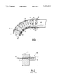
- FIG. 1 is a partial side elevation showing the bending section and the viewing head of an endoscopic or borescopic insertion tube which utilizes termination devices embodying the teachings of the present invention
- FIG. 2 is an enlarged side elevation in section, showing a prior art cable terminating device
- FIG. 3 is an enlarged side elevation showing a cylindrical spring mounted upon the distal end of a steering cable
- FIG. 4 is a greatly enlarged front view showing a spring being crimped into contact with a wire cable
- FIG. 5 is an enlarged side elevation showing one embodiment of the invention.
- FIG. 6 is an enlarged side elevation showing another embodiment of the invention.
- FIG. 7 is an enlarged side elevation showing a still further embodiment of the invention.
- FIGS. 8-10 illustrate the steps in producing a still further embodiment of the invention.
- an endoscopic or borescopic insertion tube 10 which includes a steering section 12.
- the steering section contains a series of stacked circular washers that are slidably mounted on cables 14 and 15 made of twisted strands of stainless steel.
- Each washer contains two sets of spacer beads mounted on the opposing end faces thereof. The beads are placed at 90° intervals adjacent to the outer periphery of the washer with the beads in each set lying along a common diametrical line.
- the washers are covered by a metal or plastic braid 24 and thereover by a flexible elastomeric sheath 25.
- cable 14 is passed through beads 17--17 that are located on one face of each washer, while cable 15 is similarly passed through beads 18--18, located on the opposite face of each washer.
- the beads are placed on the cables in an arrangement as shown in FIG. 1 with beads 17 on one washer riding in contact with the beads 17 on an adjacent washer.
- beads 18 on one washer are mounted in riding contact with beads 18 on an adjacent washer.
- the cables are connected to individual control pulleys or gear racks located in the control handle of the instrument (not shown) with the distal end of the cables being passed through an end plate 20.
- a terminating device embodying the present invention is secured to the distal end of each cable that prevents the cable from being pulled back through the end plate.
- the end plate 20 is connected by any suitable means to the viewing head 23 of the insertion tube.
- the viewing head will contain a CCD imager for recording image data relating to a remote target within the viewing range of the instrument.
- the recorded image data is converted into electrical signals that are transmitted back through the insertion tube to the video section (not shown) for processing and viewing.
- the viewing head of the instrument can be articulated by pulling on selected cables. This, in turn, causes the associated terminating units to be pulled with some force against the end plate.
- FIG. 2 there is shown a typical terminating device 30 found in the prior art.
- the distal end of a steering cable 14, 15 is passed through an opening 31 formed in the end plate 20.
- a brass cylinder 33 is positioned over the distal end of the cable and a solder joint 34 is formed between the cylinder and the cable.
- the cable is about 0.02 inches in diameter and the terminator cylinder is about 0.10 inches long and has an outside diameter of about 0.043 inches and an inside diameter of about 0.028 inches.
- the solder joint if properly formed, generally exhibits good strength at the time a load is initially applied to the cylinder. However, the joint can fail under repeated or sustained loading with failure being similar to load dependent creep failure.
- one of the objects of the present invention is to increase the joint strength of a terminating unit without sacrificing the many advantages associated with this type of device.
- the terminating unit 40 (FIG. 5), of the present invention includes a cylindrical, helically wound spring element 41 formed of a single strand of stainless steel.
- the spring is initially slipped over the distal end of a cable 43 as shown in FIG. 3.
- the spring is crimped or deformed inwardly along its entire length using a three jaw universal chuck 45 as illustrated in FIG. 4.
- the three jaws 46--46 of the chuck are equally spaced at 120° intervals and are driven into contact simultaneously with the spring to deform the spring into a triangular shape as shown.
- the spring is crimped into locking contact against the cable to form a mechanical joint therebetween.
- solder 43 (FIG. 5) is flowed onto and through the spring to wet the spring surfaces and the cable.
- the solder penetrates the spring in the spaces between the coils which, during the crimping operation, are slightly opened and impregnates the wire strands of the cable.
- the solder forms an extremely strong joint between the spring and the cable which is substantially free of cold joints.
- the solder also holds the strands of the cable together in the event that the cable does pull out of the spring under excessive loading. Keeping the strands together prevents damage to the endoscope or borescope that could be caused by ends of frayed cable strands.
- the proximal end of the spring equipped terminating unit 40 still retains the proximal end tang 48p which faces the end plate 20.
- the tang typically protrudes outside the solder envelope 43 and thus has a potential to cause damage to components of the endoscope or borescope. Additionally, the tang accepts some of the axial loading on the cable and may shift its position upon application of an initial load thereby affecting cable performance during a steering maneuver.
- a stainless steel washer 50 (FIG. 6) may be placed over the cable at the proximal end of the spring.
- the spring is initially crimped to the cable as explained above.
- the jaws of the crimping tool are brought into contact with the washer and sufficient force is applied to hold the washer firmly in the jaws.
- the cable is pulled through the washer with sufficient axial force to bend the proximal end tang of the spring back into the crimped spring structure.
- the jaws of the tool are then tightened to crimp both the washer and the spring simultaneously into deforming locking contact with the cable.
- the structure is soldered as noted above and the distal ends of the cable and the spring are trimmed to form a flat distal end face on the assembly.
- a terminating structure 60 as illustrated in FIG. 7 can also be obtained by first crimping the spring upon a rigid solid steel mandrel having a diameter slightly greater than the diameter of the cable. After the initial crimping operation is completed, one end of the precrimped spring is trimmed to remove the end tang. The spring is removed from the mandrel and mounted upon the distal end of the cable with the trimmed end toward the proximal end of the cable. The spring is now further crimped into deforming contact against the cable, and the solder joint is formed. The distal end of the spring and the cable are trimmed as previously noted to produce the structure illustrated in FIG. 7. Ten terminator units of the type shown in FIG. 7 were tested for initial strength.
- the average load at failure was 61 pounds with the minimum load at failure being 53 pounds.
- the time to failure in all cases exceeded one week. It was also found that about a 12% increase in initial load strength can be obtained by covering the distal end of the spring and the cable with solder after the distal end trimming operation has been completed.
- FIGS. 8-10 A still further embodiment of the present invention is illustrated by FIGS. 8-10.
- a spring 70 having an inside diameter of 0.025 inches and wire size of 0.009 inches is placed on the distal end of a 0.02 inch diameter cable 43.
- the distal end of the spring is then crimped into contact against the cable using a three jaw chuck.
- the jaws of the chuck are tapered so that the spring is tapered downwardly as shown in FIG. 8 from the proximal end thereof towards the distal end so that each successive coil in the crimped section exerts a higher holding force on the cable. From one to three coils 71 at the proximal end of the spring remain uncrimped and as a result no tang is formed at the proximal end of the spring.
- Terminated cables using the tapered spring arrangement have been constructed and tested.
- the termination units exhibited an average breaking strength at initial loading about that of a bare cable, that is, a breaking strength of about 70 pounds.
- Long term steady load testing also confirms that this type of termination unit lasts far longer than terminating devices presently found in the prior art.
- solder joint Although the unit illustrated in FIG. 10 includes a solder joint, it is believed that the use of solder in this embodiment is not necessary because of high strength exhibited by the mechanical joint produced by the crimping operation.
Abstract
Description
Claims (9)
Priority Applications (1)
| Application Number | Priority Date | Filing Date | Title |
|---|---|---|---|
| US08/075,330 US5435296A (en) | 1993-06-11 | 1993-06-11 | Endoscope having crimped and soldered cable terminator |
Applications Claiming Priority (1)
| Application Number | Priority Date | Filing Date | Title |
|---|---|---|---|
| US08/075,330 US5435296A (en) | 1993-06-11 | 1993-06-11 | Endoscope having crimped and soldered cable terminator |
Publications (1)
| Publication Number | Publication Date |
|---|---|
| US5435296A true US5435296A (en) | 1995-07-25 |
Family
ID=22125007
Family Applications (1)
| Application Number | Title | Priority Date | Filing Date |
|---|---|---|---|
| US08/075,330 Expired - Lifetime US5435296A (en) | 1993-06-11 | 1993-06-11 | Endoscope having crimped and soldered cable terminator |
Country Status (1)
| Country | Link |
|---|---|
| US (1) | US5435296A (en) |
Cited By (29)
| Publication number | Priority date | Publication date | Assignee | Title |
|---|---|---|---|---|
| US6402738B1 (en) * | 1999-02-04 | 2002-06-11 | Asahi Kogaku Kogyo Kabushiki Kaisha | Wire connection structure for endoscope |
| US20030194793A1 (en) * | 1997-03-31 | 2003-10-16 | Genentech, Inc. | Secreted and transmembrane polypeptides and nucleic acids encoding the same |
| US20040183900A1 (en) * | 2003-03-20 | 2004-09-23 | Everest Vit | Method and system for automatically detecting defects in remote video inspection applications |
| US20050129108A1 (en) * | 2003-01-29 | 2005-06-16 | Everest Vit, Inc. | Remote video inspection system |
| US20060072903A1 (en) * | 2001-02-22 | 2006-04-06 | Everest Vit, Inc. | Method and system for storing calibration data within image files |
| US20070070340A1 (en) * | 2005-06-22 | 2007-03-29 | Karpen Thomas W | Remote video inspection system integrating audio communication functionality |
| US20070091183A1 (en) * | 2005-10-21 | 2007-04-26 | Ge Inspection Technologies, Lp | Method and apparatus for adapting the operation of a remote viewing device to correct optical misalignment |
| US20070156018A1 (en) * | 2005-06-24 | 2007-07-05 | Krauter Allan I | Insertion tube storage carousel |
| US20070156021A1 (en) * | 2005-09-14 | 2007-07-05 | Bradford Morse | Remote imaging apparatus having an adaptive lens |
| US20070187574A1 (en) * | 2006-02-13 | 2007-08-16 | Ge Inspection Technologies, Lp | Electronic imaging device with photosensor arrays |
| US20070225931A1 (en) * | 2006-03-27 | 2007-09-27 | Ge Inspection Technologies, Lp | Inspection apparatus for inspecting articles |
| US20080151046A1 (en) * | 2006-12-22 | 2008-06-26 | Ge Inspection Technologies, Lp | Heat protection systems and methods for remote viewing devices |
| US20080158348A1 (en) * | 2006-12-29 | 2008-07-03 | General Electric Company | Inspection apparatus having illumination assembly |
| US20080157994A1 (en) * | 2006-12-29 | 2008-07-03 | General Electric Company | IP based voice communication enabled inspection system |
| US7422559B2 (en) | 2004-06-16 | 2008-09-09 | Ge Inspection Technologies, Lp | Borescope comprising fluid supply system |
| US20090106948A1 (en) * | 2007-10-26 | 2009-04-30 | Lopez Joseph V | Method and apparatus for retaining elongated flexible articles including visual inspection apparatus inspection probes |
| US20090109045A1 (en) * | 2007-10-26 | 2009-04-30 | Delmonico James J | Battery and power management for industrial inspection handset |
| US20090109429A1 (en) * | 2007-10-26 | 2009-04-30 | Joshua Lynn Scott | Inspection apparatus having heat sink assembly |
| US20090109283A1 (en) * | 2007-10-26 | 2009-04-30 | Joshua Lynn Scott | Integrated storage for industrial inspection handset |
| US7564626B2 (en) | 2002-01-25 | 2009-07-21 | Ge Inspection Technologies Lp | Stereo-measurement borescope with 3-D viewing |
| US20090216245A1 (en) * | 2008-02-26 | 2009-08-27 | Tyco Healthcare Group Lp | Flexible Hollow Spine With Locking Feature And Manipulation Structure |
| US20100048051A1 (en) * | 2008-02-21 | 2010-02-25 | Melni Mark L | Electrical connectors and methods of manufacturing and using same |
| US20100314443A1 (en) * | 2009-06-12 | 2010-12-16 | Hand Held Products, Inc. | Portable Data Terminal |
| US20110097948A1 (en) * | 2008-02-21 | 2011-04-28 | Melni Mark L | Electrical connectors and methods of manufacturing and using same |
| US8213676B2 (en) | 2006-12-20 | 2012-07-03 | Ge Inspection Technologies Lp | Inspection apparatus method and apparatus comprising motion responsive control |
| US8310604B2 (en) | 2007-10-26 | 2012-11-13 | GE Sensing & Inspection Technologies, LP | Visual inspection apparatus having light source bank |
| US8810636B2 (en) | 2006-12-20 | 2014-08-19 | Ge Inspection Technologies, Lp | Inspection apparatus method and apparatus comprising selective frame output |
| US10291850B2 (en) | 2006-12-20 | 2019-05-14 | General Electric Company | Inspection apparatus method and apparatus comprising selective frame output |
| US10942964B2 (en) | 2009-02-02 | 2021-03-09 | Hand Held Products, Inc. | Apparatus and method of embedding meta-data in a captured image |
Citations (7)
| Publication number | Priority date | Publication date | Assignee | Title |
|---|---|---|---|---|
| US3203078A (en) * | 1963-01-04 | 1965-08-31 | Buchanan Electrical Prod Corp | Method of making an electrical connection |
| US3333047A (en) * | 1965-01-13 | 1967-07-25 | Geoffroi Louis Emil Gerard | Electrical connector with pre-placed solder |
| US4035577A (en) * | 1973-06-04 | 1977-07-12 | Thomas & Betts Corporation | Tubular ferrule |
| US4135296A (en) * | 1977-08-19 | 1979-01-23 | The United States Of America As Represented By The Secretary Of The Air Force | Method of joining a fine wire filament to a connector |
| US4735259A (en) * | 1984-02-21 | 1988-04-05 | Hewlett-Packard Company | Heated transfer line for capillary tubing |
| US4770185A (en) * | 1983-02-14 | 1988-09-13 | The Board Of Regents Of The University Of Washington | Method and apparatus for endoscopic blood flow detection by the use of ultrasonic energy |
| US4796607A (en) * | 1987-07-28 | 1989-01-10 | Welch Allyn, Inc. | Endoscope steering section |
-
1993
- 1993-06-11 US US08/075,330 patent/US5435296A/en not_active Expired - Lifetime
Patent Citations (7)
| Publication number | Priority date | Publication date | Assignee | Title |
|---|---|---|---|---|
| US3203078A (en) * | 1963-01-04 | 1965-08-31 | Buchanan Electrical Prod Corp | Method of making an electrical connection |
| US3333047A (en) * | 1965-01-13 | 1967-07-25 | Geoffroi Louis Emil Gerard | Electrical connector with pre-placed solder |
| US4035577A (en) * | 1973-06-04 | 1977-07-12 | Thomas & Betts Corporation | Tubular ferrule |
| US4135296A (en) * | 1977-08-19 | 1979-01-23 | The United States Of America As Represented By The Secretary Of The Air Force | Method of joining a fine wire filament to a connector |
| US4770185A (en) * | 1983-02-14 | 1988-09-13 | The Board Of Regents Of The University Of Washington | Method and apparatus for endoscopic blood flow detection by the use of ultrasonic energy |
| US4735259A (en) * | 1984-02-21 | 1988-04-05 | Hewlett-Packard Company | Heated transfer line for capillary tubing |
| US4796607A (en) * | 1987-07-28 | 1989-01-10 | Welch Allyn, Inc. | Endoscope steering section |
Cited By (54)
| Publication number | Priority date | Publication date | Assignee | Title |
|---|---|---|---|---|
| US20030194793A1 (en) * | 1997-03-31 | 2003-10-16 | Genentech, Inc. | Secreted and transmembrane polypeptides and nucleic acids encoding the same |
| US6402738B1 (en) * | 1999-02-04 | 2002-06-11 | Asahi Kogaku Kogyo Kabushiki Kaisha | Wire connection structure for endoscope |
| US20060072903A1 (en) * | 2001-02-22 | 2006-04-06 | Everest Vit, Inc. | Method and system for storing calibration data within image files |
| US7564626B2 (en) | 2002-01-25 | 2009-07-21 | Ge Inspection Technologies Lp | Stereo-measurement borescope with 3-D viewing |
| US20050129108A1 (en) * | 2003-01-29 | 2005-06-16 | Everest Vit, Inc. | Remote video inspection system |
| US20080116093A1 (en) * | 2003-01-29 | 2008-05-22 | Ge Inspection Technologies Lp | Apparatus for storing an insertion tube |
| US20040183900A1 (en) * | 2003-03-20 | 2004-09-23 | Everest Vit | Method and system for automatically detecting defects in remote video inspection applications |
| US7422559B2 (en) | 2004-06-16 | 2008-09-09 | Ge Inspection Technologies, Lp | Borescope comprising fluid supply system |
| US7956888B2 (en) | 2005-06-22 | 2011-06-07 | Ge Inspection Technologies, Lp | Remote video inspection system integrating audio communication functionality |
| US20070070340A1 (en) * | 2005-06-22 | 2007-03-29 | Karpen Thomas W | Remote video inspection system integrating audio communication functionality |
| US20070156018A1 (en) * | 2005-06-24 | 2007-07-05 | Krauter Allan I | Insertion tube storage carousel |
| US7819798B2 (en) | 2005-06-24 | 2010-10-26 | Ge Inspection Technologies, Lp | Insertion tube storage carousel |
| US20070156021A1 (en) * | 2005-09-14 | 2007-07-05 | Bradford Morse | Remote imaging apparatus having an adaptive lens |
| US20070091183A1 (en) * | 2005-10-21 | 2007-04-26 | Ge Inspection Technologies, Lp | Method and apparatus for adapting the operation of a remote viewing device to correct optical misalignment |
| US20070187574A1 (en) * | 2006-02-13 | 2007-08-16 | Ge Inspection Technologies, Lp | Electronic imaging device with photosensor arrays |
| US7679041B2 (en) | 2006-02-13 | 2010-03-16 | Ge Inspection Technologies, Lp | Electronic imaging device with photosensor arrays |
| US20070226258A1 (en) * | 2006-03-27 | 2007-09-27 | Thomas Eldred Lambdin | Article inspection apparatus |
| US8368749B2 (en) | 2006-03-27 | 2013-02-05 | Ge Inspection Technologies Lp | Article inspection apparatus |
| US8310533B2 (en) | 2006-03-27 | 2012-11-13 | GE Sensing & Inspection Technologies, LP | Inspection apparatus for inspecting articles |
| US20070225931A1 (en) * | 2006-03-27 | 2007-09-27 | Ge Inspection Technologies, Lp | Inspection apparatus for inspecting articles |
| US10291850B2 (en) | 2006-12-20 | 2019-05-14 | General Electric Company | Inspection apparatus method and apparatus comprising selective frame output |
| US9621808B2 (en) | 2006-12-20 | 2017-04-11 | General Electric Company | Inspection apparatus method and apparatus comprising selective frame output |
| US8810636B2 (en) | 2006-12-20 | 2014-08-19 | Ge Inspection Technologies, Lp | Inspection apparatus method and apparatus comprising selective frame output |
| US8213676B2 (en) | 2006-12-20 | 2012-07-03 | Ge Inspection Technologies Lp | Inspection apparatus method and apparatus comprising motion responsive control |
| US20080151046A1 (en) * | 2006-12-22 | 2008-06-26 | Ge Inspection Technologies, Lp | Heat protection systems and methods for remote viewing devices |
| US8118733B2 (en) | 2006-12-22 | 2012-02-21 | Ge Inspection Technologies, Lp | Heat protection systems and methods for remote viewing devices |
| US8625434B2 (en) | 2006-12-29 | 2014-01-07 | Ge Inspection Technologies Lp | IP based voice communication enabled inspection system |
| US20080158348A1 (en) * | 2006-12-29 | 2008-07-03 | General Electric Company | Inspection apparatus having illumination assembly |
| US20080157994A1 (en) * | 2006-12-29 | 2008-07-03 | General Electric Company | IP based voice communication enabled inspection system |
| US8514278B2 (en) | 2006-12-29 | 2013-08-20 | Ge Inspection Technologies Lp | Inspection apparatus having illumination assembly |
| US7902990B2 (en) | 2007-10-26 | 2011-03-08 | Ge Inspection Technologies, Lp | Battery and power management for industrial inspection handset |
| US8767060B2 (en) | 2007-10-26 | 2014-07-01 | Ge Inspection Technologies, Lp | Inspection apparatus having heat sink assembly |
| US20090106948A1 (en) * | 2007-10-26 | 2009-04-30 | Lopez Joseph V | Method and apparatus for retaining elongated flexible articles including visual inspection apparatus inspection probes |
| US8310604B2 (en) | 2007-10-26 | 2012-11-13 | GE Sensing & Inspection Technologies, LP | Visual inspection apparatus having light source bank |
| US20090109283A1 (en) * | 2007-10-26 | 2009-04-30 | Joshua Lynn Scott | Integrated storage for industrial inspection handset |
| US20090109045A1 (en) * | 2007-10-26 | 2009-04-30 | Delmonico James J | Battery and power management for industrial inspection handset |
| US20090109429A1 (en) * | 2007-10-26 | 2009-04-30 | Joshua Lynn Scott | Inspection apparatus having heat sink assembly |
| US8253782B2 (en) | 2007-10-26 | 2012-08-28 | Ge Inspection Technologies, Lp | Integrated storage for industrial inspection handset |
| US8066525B2 (en) | 2008-02-21 | 2011-11-29 | Melni Mark L | Electrical connectors and methods of manufacturing and using same |
| US9614304B2 (en) | 2008-02-21 | 2017-04-04 | Melni, Llc | Electrical connectors and methods of manufacturing and using same |
| US20100048051A1 (en) * | 2008-02-21 | 2010-02-25 | Melni Mark L | Electrical connectors and methods of manufacturing and using same |
| US7794255B2 (en) | 2008-02-21 | 2010-09-14 | Melni Mark L | Electrical connectors and methods of manufacturing and using same |
| US8246370B2 (en) | 2008-02-21 | 2012-08-21 | Melni Mark L | Electrical connectors and methods of manufacturing and using same |
| US20110097948A1 (en) * | 2008-02-21 | 2011-04-28 | Melni Mark L | Electrical connectors and methods of manufacturing and using same |
| US8771000B2 (en) | 2008-02-21 | 2014-07-08 | Melni, Llc | Electrical connectors and methods of manufacturing and using same |
| US7901233B2 (en) | 2008-02-21 | 2011-03-08 | Melni Mark L | Electrical connectors and methods of manufacturing and using same |
| US9608346B2 (en) | 2008-02-21 | 2017-03-28 | Melni, Llc | Mechanical and/or electrical connector with axial-pull apparatus and methods |
| US20090216245A1 (en) * | 2008-02-26 | 2009-08-27 | Tyco Healthcare Group Lp | Flexible Hollow Spine With Locking Feature And Manipulation Structure |
| US8246575B2 (en) | 2008-02-26 | 2012-08-21 | Tyco Healthcare Group Lp | Flexible hollow spine with locking feature and manipulation structure |
| US10942964B2 (en) | 2009-02-02 | 2021-03-09 | Hand Held Products, Inc. | Apparatus and method of embedding meta-data in a captured image |
| US9519814B2 (en) | 2009-06-12 | 2016-12-13 | Hand Held Products, Inc. | Portable data terminal |
| US20100314443A1 (en) * | 2009-06-12 | 2010-12-16 | Hand Held Products, Inc. | Portable Data Terminal |
| US9959495B2 (en) | 2009-06-12 | 2018-05-01 | Hand Held Products, Inc. | Portable data terminal |
| US11042793B2 (en) | 2009-06-12 | 2021-06-22 | Hand Held Products, Inc. | Portable data terminal |
Similar Documents
| Publication | Publication Date | Title |
|---|---|---|
| US5435296A (en) | Endoscope having crimped and soldered cable terminator | |
| US3858848A (en) | Fish tape | |
| US4447120A (en) | Fiber optic cable clamp | |
| US6299612B1 (en) | Wire loop type instrument for endoscope and method of producing the same | |
| US4203647A (en) | Electric sockets for plug and socket connectors and methods for their manufacture | |
| US6726568B2 (en) | Coil shaft and method for fabricating same | |
| TWI323539B (en) | Coaxial cable connector with clamping insert | |
| US5885207A (en) | Flexible tube of endoscope | |
| US4585304A (en) | Technique for repairing and joining small diameter optical fiber cables | |
| JPH0231571B2 (en) | ||
| JP2001157661A (en) | Connection structure of operating wire for endoscope | |
| CN202076580U (en) | Wire assembly | |
| US4453034A (en) | One die system of compression transmission fittings | |
| JP2019022314A (en) | Assembly component for compression connection member, compression connection structure for power transmission line, and construction method for compression connection member | |
| US5378855A (en) | Electrical connector | |
| US4874909A (en) | Electrical splice connector | |
| CA2084410C (en) | Electrical connector | |
| CA1049111A (en) | Electrical connector having a compression barrel and deformable core grip | |
| US20080009202A1 (en) | Wire connector and method of fabricating the same | |
| US20170010458A1 (en) | Endoscope | |
| US2247928A (en) | Coupling | |
| US4215463A (en) | Method of field forming a loop splice for wire rope | |
| US5095178A (en) | Electrical connector and method | |
| KR100191693B1 (en) | An electrical ground for a flexible hose and method of making | |
| GB2069170A (en) | Crimp sleeve, especially for optical fibre cables |
Legal Events
| Date | Code | Title | Description |
|---|---|---|---|
| AS | Assignment |
Owner name: WELCH ALLYN, INC., NEW YORK Free format text: ASSIGNMENT OF ASSIGNORS INTEREST;ASSIGNORS:VIVENZIO, ROBERT L.;KRAUTER, ALLAN I.;KEHOSKIE, MICHAEL P.;REEL/FRAME:006594/0395 Effective date: 19930514 |
|
| STPP | Information on status: patent application and granting procedure in general |
Free format text: APPLICATION UNDERGOING PREEXAM PROCESSING |
|
| FEPP | Fee payment procedure |
Free format text: PAYOR NUMBER ASSIGNED (ORIGINAL EVENT CODE: ASPN); ENTITY STATUS OF PATENT OWNER: LARGE ENTITY |
|
| FEPP | Fee payment procedure |
Free format text: PAYOR NUMBER ASSIGNED (ORIGINAL EVENT CODE: ASPN); ENTITY STATUS OF PATENT OWNER: LARGE ENTITY Free format text: PAYER NUMBER DE-ASSIGNED (ORIGINAL EVENT CODE: RMPN); ENTITY STATUS OF PATENT OWNER: LARGE ENTITY |
|
| FPAY | Fee payment |
Year of fee payment: 4 |
|
| FPAY | Fee payment |
Year of fee payment: 8 |
|
| AS | Assignment |
Owner name: EVEREST VIT, INC., NEW JERSEY Free format text: ASSIGNMENT OF ASSIGNORS INTEREST;ASSIGNOR:WELCH ALLYN, INC.;REEL/FRAME:015698/0980 Effective date: 20040602 |
|
| AS | Assignment |
Owner name: GE INSPECTION TECHNOLOGIES, LP, PENNSYLVANIA Free format text: ASSIGNMENT OF ASSIGNORS INTEREST;ASSIGNOR:EVEREST VIT, INC.;REEL/FRAME:018047/0642 Effective date: 20060331 |
|
| FPAY | Fee payment |
Year of fee payment: 12 |