US5354629A - Monaqueous electrolyte battery - Google Patents
Monaqueous electrolyte battery Download PDFInfo
- Publication number
- US5354629A US5354629A US07/959,128 US95912892A US5354629A US 5354629 A US5354629 A US 5354629A US 95912892 A US95912892 A US 95912892A US 5354629 A US5354629 A US 5354629A
- Authority
- US
- United States
- Prior art keywords
- anode
- cathode
- electrode unit
- terminal tab
- anode terminal
- Prior art date
- Legal status (The legal status is an assumption and is not a legal conclusion. Google has not performed a legal analysis and makes no representation as to the accuracy of the status listed.)
- Expired - Lifetime
Links
Images


Classifications
-
- H—ELECTRICITY
- H01—ELECTRIC ELEMENTS
- H01M—PROCESSES OR MEANS, e.g. BATTERIES, FOR THE DIRECT CONVERSION OF CHEMICAL ENERGY INTO ELECTRICAL ENERGY
- H01M50/00—Constructional details or processes of manufacture of the non-active parts of electrochemical cells other than fuel cells, e.g. hybrid cells
- H01M50/50—Current conducting connections for cells or batteries
- H01M50/531—Electrode connections inside a battery casing
- H01M50/534—Electrode connections inside a battery casing characterised by the material of the leads or tabs
-
- H—ELECTRICITY
- H01—ELECTRIC ELEMENTS
- H01M—PROCESSES OR MEANS, e.g. BATTERIES, FOR THE DIRECT CONVERSION OF CHEMICAL ENERGY INTO ELECTRICAL ENERGY
- H01M50/00—Constructional details or processes of manufacture of the non-active parts of electrochemical cells other than fuel cells, e.g. hybrid cells
- H01M50/50—Current conducting connections for cells or batteries
- H01M50/531—Electrode connections inside a battery casing
- H01M50/536—Electrode connections inside a battery casing characterised by the method of fixing the leads to the electrodes, e.g. by welding
-
- H—ELECTRICITY
- H01—ELECTRIC ELEMENTS
- H01M—PROCESSES OR MEANS, e.g. BATTERIES, FOR THE DIRECT CONVERSION OF CHEMICAL ENERGY INTO ELECTRICAL ENERGY
- H01M2200/00—Safety devices for primary or secondary batteries
-
- H—ELECTRICITY
- H01—ELECTRIC ELEMENTS
- H01M—PROCESSES OR MEANS, e.g. BATTERIES, FOR THE DIRECT CONVERSION OF CHEMICAL ENERGY INTO ELECTRICAL ENERGY
- H01M6/00—Primary cells; Manufacture thereof
- H01M6/04—Cells with aqueous electrolyte
- H01M6/06—Dry cells, i.e. cells wherein the electrolyte is rendered non-fluid
- H01M6/10—Dry cells, i.e. cells wherein the electrolyte is rendered non-fluid with wound or folded electrodes
Definitions
- This invention relates to a nonaqueous electrolyte battery provided with a cathode having an active material such as a metal oxide or sulfide, an anode comprising a consumable metal such as lithium, and a separator rolled into a spiral electrode unit.
- a cathode having an active material such as a metal oxide or sulfide, an anode comprising a consumable metal such as lithium, and a separator rolled into a spiral electrode unit.
- the anode is placed around the outermost periphery of the electrode unit to make sufficient use of the active cathode material.
- a nonaqueous electrolyte battery having the anode around the outermost periphery of the electrode unit is described in Japanese patent disclosures 53-29933 (1978) and 63-6988 (1988).
- the thin anode battery can reduce lithium deposition on the cathode during complete discharge, anodes are easily broken during the electrode rolling process and manufacturability is degraded. Further, by reducing the anode thickness, the actual capacity of the anode is reduced bringing about a large performance degradation.
- Batteries with both the cathode and anode made thin and the electrode area increased can reduce the amount of lithium deposited per unit area of cathode because the electrode surface area is large.
- these batteries require large reductions in both cathode and anode thicknesses.
- internal resistance is reduced and large currents flow when the battery is shorted externally. Large currents cause battery overheating, and internal shorting due to separator melting becomes a concern.
- the present invention was developed to solve the previously mentioned problems. It is thus a primary object of the present invention to provide a nonaqueous electrolyte battery that prevents anode migration to, and deposition on the cathode surface induced by conditions such as overdrawing power from the battery, by disconnecting the outermost turn of the anode remaining after discharge from the anode terminal tab.
- the nonaqueous electrolyte battery of this invention is provided with a spiral electrode unit having an anode outer perimeter and comprising a belt shaped cathode, a belt shaped anode made of a consumable metal that depleted during the discharge reaction, and a separator rolled in between the cathode-anode laminate.
- the battery of the present invention has the following unique structure. Namely, the nonaqueous electrolyte battery of this invention has an anode terminal tab attached to the anode at a position at least one turn away from the outside end of the rolled anode, and that anode terminal tab is disconnected from the anode remaining in the outermost periphery after discharge. Therefore, the remaining anode does not conduct when power is overdrawn from the battery, avoiding deposition of the remaining anode on time cathode, and preventing internal shorts.
- the outermost end of time rolled cathode protrude beyond the outermost end of the rolled anode.
- the protruding end of the rolled cathode causes local acceleration of anode depletion thereby allowing reliable separation of time anode terminal tab from the remaining anode.
- terminal separation holes opened through a portion of the anode to separate the anode terminal tab from time anode remaining after discharge. Terminal separation holes insure separation of time anode terminal tab from the anode remaining after discharge by initially removing part of the anode covered by the anode terminal tab. This region sees reduced depletion due to coverage.
- FIG. 1 is a plan view showing a method of anode construction of the present invention.
- FIG. 2 is a plan view showing a method of cathode construction of the present invention.
- FIG. 3a is a cross-sectional side view showing an electrode unit W of the present invention.
- FIG. 3b is a cross-sectional side view showing the electrode unit W in the later stages of discharge.
- FIG. 4 is a plan view showing another method of anode construction of the present invention.
- FIG. 5 is a plan view showing still another method of anode construction of the present invention.
- FIG. 6a is a cross-sectional side view showing an electrode unit X of the present invention.
- FIG. 6b is a cross-sectional side view showing the electrode unit X after 50% battery discharge.
- FIG. 6c is a cross-sectional side view showing the electrode unit X In the later stages of discharge.
- FIG. 7 is a plan view showing another method of anode construction of the present invention.
- FIG. 8a is a cross-sectional side view showing an electrode unit Y of the present invention.
- FIG. 8b is a cross-sectional side view showing the electrode unit Y after 50% battery discharge.
- FIG. 8c is a cross-sectional side view showing the electrode unit Y In the later stages of discharge.
- FIG. 9 is a side view of a terminal contact embodiment of the electrode unit of the present invention.
- FIG. 10 is a cross-sectional side view showing the electrode unit Y of the present invention inserted within an exterior package.
- FIG. 11a is a cross-sectional side view showing an electrode unit Z for comparison.
- FIG. 11b is a cross-sectional side view showing the electrode unit Z in the later stages of discharge.
- FIG. 12 is a graph showing discharge characteristics of the present invention and another example for comparison.
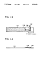
- FIG. 13 is a plan view showing another method of anode construction of the present invention.
- FIG. 14 is an edge view showing the anode of FIG. 13.
- FIG. 15 is a cross-sectional side view showing the electrode unit of the present invention enclosed within an exterior package.
- FIG. 16 is a cross-sectional side view showing an electrode unit using the anode of FIG. 13 in the later stages of discharge.
- FIG. 1 a method of anode construction is shown.
- This anode 1 is metallic lithium cut to a thickness of 0.2 mm, a width of 23 mm, and a length of 230 mm.
- a rectangular anode terminal tab 2 is connected to the anode 1 by tape 3 on both sides.
- the anode terminal tab 2 is nickel (Ni) sheet 3 mm wide and 21 mm long.
- the anode terminal tab 2 is located 180 mm down the length of the anode 1.
- the cathode 4 is fabricated in the following manner. First, 890 g of manganese dioxide is mixed with 80 g of graphite for 30 min in an automated mortar. Trifluoroethylene is added to the mixture and further mixed for 10 min. Then 15 g of polyvinyl alcohol (PVA) dissolved in 110 g of pure water is added and mixed to a slurry. This slurry coating is applied to a cathode core, dried, rolled, and cut to produce a 0.43 mm thick, 26 mm wide, and 230 mm long cathode 4. Here, 0.1 mm thick lath processed SUS304 stainless steel is used as the cathode core.
- PVA polyvinyl alcohol
- a 5 mm wide, 21 mm long region at the center of the above processed cathode 4 is stripped of coating, and a 35 mm long 3 mm wide, 0.15 mm thick strip of SUS304 stainless steel sheet is spot welded to that stripped region of exposed cathode core to form the cathode terminal tab 5.
- the cathode terminal tab 5 is covered with tape 6 except for its protruding end.
- the cathode is heat treated at 230° C. to remove moisture, and cooled in a dehydrated atmosphere.
- the cathode and anode made in the above fashion are sandwiched around a 29 mm wide polyethylene porous membrane separator. This laminate is rolled into a spiral shape, and the entire surface of the outermost circumference is covered with tape to form an electrode unit W.
- FIGS. 3a and b are cross-sectional side views showing the electrode unit W before discharge (FIG. 3a) and after discharge (FIG. 3b).
- the components are numbered as follows .
- 31 is the anode
- 34 is the cathode
- 37 is the separator
- 32 is the anode terminal tab
- 33 is tape holding the anode terminal tab 32 on the anode 31.
- This anode 41 is metallic lithium cut to a thickness of 0.2 mm, a width of 23 mm, and a length of 230 mm.
- a 0.1 mm thick, 3 mm wide, and 21 mm long Ni anode terminal tab 42 is attached to the anode 41.
- the anode terminal tab 42 is held in connection with the anode 41 by tape 43, and an ion impervious insulator material 48 in tape form is attached to the anode 41 beyond the tape which is 43 towards the end of the anode 41.
- Polyethylene-terephthalate tape 9 mm wide, 14 mm long, and 0.06 mm thick is used as the insulator material 48.
- a cathode processed by the same method as embodiment No. 1 is used for this embodiment.
- This cathode and anode are rolled around a 29 mm wide polyethylene porous membrane separator, and the entire surface of the outermost circumference is covered with tape to form the spiral electrode unit X.
- FIGS. 6a, b and c cross-sectional side views showing a spiral electrode unit X.
- Cathode change accompanying battery discharge is shown in FIG. 6a through FIG. 6c.
- the components are numbered as follows. 61 is the anode, 64 is the cathode, 67 is the separator, 62 is the anode terminal tab, 63 is tape holding the anode terminal tab 62 on the anode 61, and 68 is the ion impervious insulator material.
- This spiral electrode unit X has the following characteristics.
- the anode terminal tab 62 collects charge at a position greater than one circumference in from the end of the rolled anode 61.
- Ion impervious insulator material 68 is disposed to cover at least the entire inside surface of the region of anode 61a opposite the end region A of the cathode 64.
- the spiral electrode unit X has the ion impervious insulator material 68 disposed over more of the inside of the anode than the region 61a opposite the cathode end region A, and has the anode terminal tab 62 connected in the location shown in FIG. 6a.
- the spiral electrode unit X changes as discharge progresses from FIG. 6a to FIG. 6c.
- FIG. 6b after 50% discharge of the spiral electrode unit X, more anode 61 (inside of the outermost one turn of the anode) that opposes cathode 64 on both sides is consumed resulting in nonuniformity.
- the anode region 61a opposite the end region A of the cathode 64 is rapidly consumed resulting in more anode depletion.
- the inner region of the anode which has no ion impervious insulator material 68 depletes faster than the region with the insulator material 68 because it faces cathode 64 on both surfaces.
- part of the anode region 61a with ion impervious insulator material 68 is completely consumed due to cathode end region edge effect.
- the anode terminal tab 62 is separated from lithium remaining in the outermost one turn of anode 61 and does not electrically conduct with it.
- Embodiment No. 2 is an example of an application of embodiment No. 1.
- the spiral electrode unit X of embodiment No. 2 controls cathode edge effect by disposition of ion impervious insulator material 68 on the inside surface of the anode region 61a which is opposite the end A of the rolled cathode 64.
- This disposition of ion impervious insulator material 68 allows the anode region 61a to react only with the cathode opposite its outermost surface.
- the anode terminal tab 62 of this spiral electrode unit X disconnects from the outermost one turn of the anode 61 just prior to complete discharge. This prevents degradation of discharge characteristics and increases battery capacity compared with embodiment No. 1.
- This is because the ion impervious insulator material 68 of the spiral electrode unit X controls anode consumption thereby delaying separation of the anode terminal tab from the lithium remaining in the outermost one turn of the anode.
- the insulator material can also serve as the terminal tab tape. There is no compromise in functionality when the anode terminal tab 52 is attached with ion impervious insulator material 58.
- the insulator material is simply ion impervious material used as a barrier, and any type of porous sheet, woven material, or nonwoven material could have the same effect. Consequently, the insulator material is not strictly limited to insulating tape.
- This anode 71 is metallic lithium cut to a thickness of 0.2 mm, a width of 23 mm, and a length of 230 mm.
- Insulating film 9 is attached near the end of the metallic lithium.
- An anode terminal tab 72 is disposed on top of the insulating film 9. The anode terminal tab 72 is aligned over the insulating film such that only its end region B contacts the lithium anode.
- the anode terminal tab 72 is an L-shaped Ni sheet which is 4 mm wide, 25 mm long in one direction, and 19 mm long in the other. The end 5 mm of the 25 mm long part of the anode terminal tab 72 is contacted against the metallic lithium anode.
- the protruding part of the L-shaped anode terminal tab 72 is positioned 200 mm from the end of the metallic lithium anode.
- the anode terminal tab 72 is connected to the anode 72 by covering it with sticky tape 10 (made of polyethylene-terephthalate).
- a cathode processed by the same method as embodiment No. 1 is used for this embodiment.
- This cathode and anode are rolled around a 29 mm wide polyethylene porous membrane separator, and the entire surface of the outermost circumference is covered with tape to form a spiral electrode unit Y.
- FIGS. 8a, b and c are cross-sectional side views showing the spiral electrode unit Y. Cathode change accompanying battery discharge is shown in FIG. 8a through FIG. 8c.
- This spiral electrode unit Y has the following characteristics, 1 through 2, concerning the position and configuration of the anode terminal tab 82.
- the anode terminal tab 82 is connected to, and collects charge at a position near center, greater than or equal to one turn from the end of the rolled anode 81.
- the anode terminal tab 82 is disposed on the inside (rolled) surface of the anode 81.
- the outermost turn of the anode 81 is electrically isolated frown the anode terminal tab 82 by the insulating film 89.
- the protruding end of the anode terminal tab 82 connects with time exterior package 11 through a cathode-less part of the outer periphery of the spiral electrode unit Y.
- anode terminal tab it is not always necessary for the anode terminal tab to be L-shaped. It is also possible to contact the exterior package with an anode terminal tab 92 such as shown in FIG. 9, which is not L-shaped but is linear and has an end that extends in the direction of electrode winding and protrudes out from the end of the rolled anode.
- the spiral electrode unit Y of FIGS. 8a, b and c has the characteristic that consumption of the anode region D that is opposite the edge C of the cathode end region is particularly fast.
- the dotted line of FIG. 8b shows anode 81 consumption in regions without insulating film 89 and sticky tape 90.
- the anode region D opposite the edge C of the cathode 84 depletes rapidly due to the edge effect. Therefore, as shown by region D in FIG. 8c, the anode terminal tab 82 is separated from the residual outer turn of the lithium with certainty in the later stages of battery discharge. Hence, there is no conduction between the anode terminal tab 82 and the outermost turn of the anode in the later stages of battery discharge, no lithium dendrite growth due to overdrawing battery power, and battery safety is insured.
- the anode terminal tab can continue to connect with the outermost turn of the anode, and the overdrawing of power from the battery can be unsafe.
- FIG. 10 is a cross-sectional side view of the spiral electrode unit Y inserted within the exterior package 11.
- the distance d between the protruding end of the anode terminal tab 82 and the exterior package is short, preventing bending of the anode terminal tab 82 due to vibration, and thereby avoiding internal shorts.
- anode terminal tab is connected to the outermost turn of the metallic lithium anode.
- a metallic lithium anode is cut to 0.2 mm thick 23 mm wide, and 230 mm long, and a 3 mm wide and 21 mm long rectangular Ni sheet anode terminal tab is attached to it.
- This cathode and anode are rolled around a 29 mm wide polyethylene porous membrane separator, and the entire surface of the outermost turn is covered with tape to form the electrode unit Z.
- Cross-sectional side views of this electrode unit Z are shown in FIGS. 11a and b.
- FIG. 11a shows the spiral electrode unit before discharge, where 111 is the anode, 112 is the anode terminal tab, 113 is tape, and 114 is the cathode.
- the anode terminal tab 112 is connected to the outermost one turn of the anode and protrudes out to the bottom of the exterior package.
- FIG. 11b is a cross-sectional side view of the spiral electrode unit Z in the later stages of discharge.
- Cathode opposite anode on both sides is consumed and separated at region E.
- Lithium in the outermost circumference remains with the anode terminal tab connected.
- residual lithium in the outermost periphery electrically conducts via the anode terminal tab 112. Therefore, residual lithium ionizes and deposits on the completely reacted cathode.
- This active lithium deposition breaks through the separator to the anode and causes internal shorting and the possibility of battery fire due to sparks during shorting.
- the batteries of embodiment No. 1 through embodiment No. 3 had equal or better discharge characteristics than the example for comparison. According to this result, the embodiments of the present invention produce safe batteries without degradation of discharge characteristics.
- Prototype nonaqueous electrolyte batteries using organic electrolyte were fabricated by the following process.
- the prototypes made were MnO 2 /Li nonaqueous electrolyte batteries.
- the cathode is made by the same method as embodiment No. 1. However, the cathode sheet dimensions are 1.15 mm thick, 51 mm wide, and 385 mm long. A 5 mm by 25 mm region at the center of the cathode sheet is stripped, an SUS304 stainless steel terminal is spot welded there, and the stripped region is covered with glass tape. The terminal is 0.15 mm thick, 3 mm wide, and 35 mm long.
- a prototype cathode 131 provided with a terminal separating hole 138, was made in the following configuration.
- the anode 131 is a 0.46 mm thick lithium sheet cut to a width of 48 mm and a length of 435 mm.
- Ni anode terminal tab 132 is taped to the lithium sheet with glass tape.
- the anode terminal tab 132 is 0.15 mm thick, 3 mm wide, and 35 mm long on a side.
- a 7 mm diameter terminal separating hole 138 is provided through the anode 70 mm from the end of the anode which is rolled last.
- the terminal separating hole 138 is positioned at the boundary of the connecting region of the anode terminal tab 132 to the anode 131 and an insulating film insulating material 139.
- an insulating film used as an insulating material 139 is attached between the anode terminal tab 132 and the anode 131.
- the Ni anode terminal tab 132 is taped on top of the insulating material 139 with glass tape, and one end of the anode terminal tab 132 is connected to the anode 131 inside of the outer perimeter region.
- the anode terminal tab 132 is L-shaped. Each arm of the L-shaped anode terminal tab 132 is 0.15 mm thick, 3 mm wide, and 35 mm long. The anode terminal tab 132 is taped to the anode 40 mm from the end of the anode which is rolled last, and, when rolled, the anode terminal tab 132 is next to the outermost periphery of the anode with insulating film in between.
- a prototype battery of the configuration shown in FIG. 15 is made as follows.
- An electrode unit is made by rolling a laminate of cathode 154 and anode 151 sandwiched around a separator 157.
- the anode terminal tab 152 is connected to the bottom surface of the exterior package 1511 by spot welding.
- an insulating sleeve 1510 is placed around the electrode unit, and the cathode terminal 155 is spot welded to the bottom surface of the battery cap 1512 after grooving the top of the exterior package 1511.
- FIG. 16 This figure shows the completely discharged electrode unit using the anode of embodiment No. 4 in cross-section.
- the outermost turn of the anode 161 separates from the anode terminal tab 162 during the later stages of discharge (they are separated by insulating film in the figure). Therefore, the detrimental effect of the active anode material depositing on the cathode is avoided.
- a terminal separating hole 138 is provided through one part of the lithium sheet anode under the L-shaped anode terminal tab 132.
- the terminal separating hole provided in the anode was 7 mm in diameter.
- the battery of this invention is not restricted to this size and shape terminal separating hole in the anode. Since the terminal separating hole separates the outer perimeter the anode from anode inside during the later stages of discharge, it is satisfactory for the terminal separating hole to be larger than the width of the anode terminal tab. It is desirable to adjust the diameter of the terminal separating hole to be within a range of 3 mm to 7 mm larger than the width of the anode terminal tab.
- anode terminal tab (mechanically) connected to the remaining anode after discharge, and to suppress deposition of residual anode on the cathode of a nonaqueous electrolyte battery with a spiral electrode unit having an outer periphery anode that separates (electrically) from the anode terminal tab. Further by disposing ion impervious insulator material at least over the inside surface of the anode opposite the end of the rolled cathode, a nonaqueous electrolyte battery that efficiently uses the anode is realized.
Abstract
Description
Claims (6)
Applications Claiming Priority (4)
| Application Number | Priority Date | Filing Date | Title |
|---|---|---|---|
| JP03262219A JP3133420B2 (en) | 1991-10-09 | 1991-10-09 | Non-aqueous electrolyte battery |
| JP3-262219 | 1991-10-09 | ||
| JP4-205212 | 1992-07-31 | ||
| JP20521292A JP3402628B2 (en) | 1992-07-31 | 1992-07-31 | Organic electrolyte battery |
Publications (1)
| Publication Number | Publication Date |
|---|---|
| US5354629A true US5354629A (en) | 1994-10-11 |
Family
ID=26514917
Family Applications (1)
| Application Number | Title | Priority Date | Filing Date |
|---|---|---|---|
| US07/959,128 Expired - Lifetime US5354629A (en) | 1991-10-09 | 1992-10-09 | Monaqueous electrolyte battery |
Country Status (1)
| Country | Link |
|---|---|
| US (1) | US5354629A (en) |
Cited By (23)
| Publication number | Priority date | Publication date | Assignee | Title |
|---|---|---|---|---|
| US5965290A (en) * | 1996-01-12 | 1999-10-12 | Matsushita Electric Industrial Co., Ltd. | Non-aqueous electrolyte cell |
| US20030129481A1 (en) * | 1998-10-16 | 2003-07-10 | Hiroyuki Akashi | Solid electrolyte battery |
| US20040161665A1 (en) * | 1998-10-30 | 2004-08-19 | Sachio Akahira | Non-aqueous electrolyte cell and manufacturing method therefor |
| EP1508933A2 (en) * | 2003-08-19 | 2005-02-23 | Samsung SDI Co., Ltd. | Jelly-roll type electrode assembly and secondary battery including the same |
| US20050196667A1 (en) * | 2004-03-03 | 2005-09-08 | Eaglepicher Technologies, Llc | Anode design for a prismatically wound LiMnO2 cell |
| US20050277018A1 (en) * | 2004-05-25 | 2005-12-15 | Kim Cheon S | Secondary battery |
| US20060286454A1 (en) * | 2002-06-12 | 2006-12-21 | Kokam Co., Ltd. | Method for treating electrode tabs of crude cell for lithium secondary battery, and crude cell and lithium secondary battery according to the method |
| US20070154797A1 (en) * | 2005-12-29 | 2007-07-05 | Yooeup Hyung | Cylindrical lithium ion secondary battery |
| US20090136836A1 (en) * | 2007-11-24 | 2009-05-28 | Byd Company Limited | Battery Spacer |
| US20100086858A1 (en) * | 2004-05-25 | 2010-04-08 | Cheon Soo Kim | Secondary battery |
| EP2317591A1 (en) * | 2009-10-30 | 2011-05-04 | Greatbatch Ltd. | Screen-less anode design concepts for low cost lithium electrochemical cells for use in implantable medical device applications |
| EP2325928A3 (en) * | 2009-11-23 | 2011-07-27 | Greatbatch Ltd. | Direct resistance welding - self brazing of aluminum to molybdenum pin |
| US20130157094A1 (en) * | 2010-08-31 | 2013-06-20 | Hitachi Vehicle Energy, Ltd. | Secondary battery and method for producing the same |
| WO2013128206A1 (en) | 2012-03-02 | 2013-09-06 | Energy Diagnostics Limited | Separatorless storage battery |
| US9147875B1 (en) * | 2014-09-10 | 2015-09-29 | Cellink Corporation | Interconnect for battery packs |
| US9300007B1 (en) | 2011-01-07 | 2016-03-29 | Greatbatch Ltd. | Ultrasonic welding of lithium onto a current collector |
| CN105702912A (en) * | 2014-11-27 | 2016-06-22 | 中国电子科技集团公司第十八研究所 | Negative electrode of primary lithium battery and preparation method of negative electrode |
| US9466777B2 (en) | 2015-02-03 | 2016-10-11 | Cellink Corporation | Systems and methods for combined thermal and electrical energy transfer |
| US10118245B2 (en) | 2013-10-11 | 2018-11-06 | Greatbatch Ltd. | Sacrificial resistance weld electrode |
| US10205151B2 (en) | 2012-04-20 | 2019-02-12 | Greatbatch Ltd. | Connector from the tab of an electrode current collector to the terminal pin of a feedthrough in an electrochemical cell |
| US10211443B2 (en) | 2014-09-10 | 2019-02-19 | Cellink Corporation | Battery interconnects |
| US11456460B2 (en) | 2017-09-29 | 2022-09-27 | Panasonic Holdings Corporation | Nonaqueous electrolyte secondary battery |
| US11888180B2 (en) | 2021-03-24 | 2024-01-30 | Cellink Corporation | Multilayered flexible battery interconnects and methods of fabricating thereof |
Citations (9)
| Publication number | Priority date | Publication date | Assignee | Title |
|---|---|---|---|---|
| JPS5329933A (en) * | 1976-08-27 | 1978-03-20 | Katayama Chemical Works Co | Shipworm insecticide |
| JPS636988A (en) * | 1986-06-26 | 1988-01-12 | Noritsu Co Ltd | Interphone with television receiver |
| US4830940A (en) * | 1986-01-14 | 1989-05-16 | Wilson Greatbatch Ltd. | Non-agueous lithium battery |
| US4863815A (en) * | 1988-06-06 | 1989-09-05 | Altus Corporation | Cell design for spirally wound rechargeable alkaline metal cell |
| US4963445A (en) * | 1989-05-08 | 1990-10-16 | Eveready Battery Co., Inc. | Electrochemical cells having spirally wound electrode assemblies |
| US5047300A (en) * | 1989-06-14 | 1991-09-10 | Bolder Battery, Inc. | Ultra-thin plate electrochemical cell |
| JPH0462755A (en) * | 1990-06-29 | 1992-02-27 | Sanyo Electric Co Ltd | Organic electrolyte battery |
| US5114804A (en) * | 1981-08-13 | 1992-05-19 | Moli Energy Limited | Battery and method of making the battery |
| US5176968A (en) * | 1990-12-27 | 1993-01-05 | Duracell Inc. | Electrochemical cell |
-
1992
- 1992-10-09 US US07/959,128 patent/US5354629A/en not_active Expired - Lifetime
Patent Citations (9)
| Publication number | Priority date | Publication date | Assignee | Title |
|---|---|---|---|---|
| JPS5329933A (en) * | 1976-08-27 | 1978-03-20 | Katayama Chemical Works Co | Shipworm insecticide |
| US5114804A (en) * | 1981-08-13 | 1992-05-19 | Moli Energy Limited | Battery and method of making the battery |
| US4830940A (en) * | 1986-01-14 | 1989-05-16 | Wilson Greatbatch Ltd. | Non-agueous lithium battery |
| JPS636988A (en) * | 1986-06-26 | 1988-01-12 | Noritsu Co Ltd | Interphone with television receiver |
| US4863815A (en) * | 1988-06-06 | 1989-09-05 | Altus Corporation | Cell design for spirally wound rechargeable alkaline metal cell |
| US4963445A (en) * | 1989-05-08 | 1990-10-16 | Eveready Battery Co., Inc. | Electrochemical cells having spirally wound electrode assemblies |
| US5047300A (en) * | 1989-06-14 | 1991-09-10 | Bolder Battery, Inc. | Ultra-thin plate electrochemical cell |
| JPH0462755A (en) * | 1990-06-29 | 1992-02-27 | Sanyo Electric Co Ltd | Organic electrolyte battery |
| US5176968A (en) * | 1990-12-27 | 1993-01-05 | Duracell Inc. | Electrochemical cell |
Cited By (54)
| Publication number | Priority date | Publication date | Assignee | Title |
|---|---|---|---|---|
| US5965290A (en) * | 1996-01-12 | 1999-10-12 | Matsushita Electric Industrial Co., Ltd. | Non-aqueous electrolyte cell |
| US6921607B2 (en) * | 1998-10-16 | 2005-07-26 | Sony Corporation | Solid electrolyte battery |
| US20030129481A1 (en) * | 1998-10-16 | 2003-07-10 | Hiroyuki Akashi | Solid electrolyte battery |
| US7781090B2 (en) * | 1998-10-16 | 2010-08-24 | Sony Corporation | Solid electrolyte battery |
| US20050227142A1 (en) * | 1998-10-16 | 2005-10-13 | Hiroyuki Akashi | Solid electrolyte battery |
| US7157179B2 (en) * | 1998-10-30 | 2007-01-02 | Sony Corporation | Non-aqueous electrolyte cell and manufacturing method therefor |
| US20040161665A1 (en) * | 1998-10-30 | 2004-08-19 | Sachio Akahira | Non-aqueous electrolyte cell and manufacturing method therefor |
| US20060286454A1 (en) * | 2002-06-12 | 2006-12-21 | Kokam Co., Ltd. | Method for treating electrode tabs of crude cell for lithium secondary battery, and crude cell and lithium secondary battery according to the method |
| US20080028598A1 (en) * | 2002-06-12 | 2008-02-07 | Kokam Co., Ltd. | Method for Treating Electrode Tabs of Crude Cell for Lithium Secondary Battery, and Crude Cell and Lithium Secondary Battery According to the Method |
| US20080083113A1 (en) * | 2002-06-12 | 2008-04-10 | Kokam Co., Ltd. | Method for Treating Electrode Tabs of Crude Cell for Lithium Secondary Battery, and Crude Cell and Lithium Secondary Battery According to the Method |
| US20050042516A1 (en) * | 2003-08-19 | 2005-02-24 | Samsung Sdi Co., Ltd. | Jelly-roll type electrode assembly and secondary battery including the same |
| US7897279B2 (en) | 2003-08-19 | 2011-03-01 | Samsung Sdi Co., Ltd. | Jelly-roll type electrode assembly and secondary battery including the same |
| EP1508933A2 (en) * | 2003-08-19 | 2005-02-23 | Samsung SDI Co., Ltd. | Jelly-roll type electrode assembly and secondary battery including the same |
| US7850743B2 (en) | 2003-08-19 | 2010-12-14 | Samsung Sdi Co., Ltd. | Jelly-roll type electrode assembly and secondary battery including the same |
| US7785736B2 (en) | 2003-08-19 | 2010-08-31 | Samsung Sdi Co., Ltd. | Jelly-roll type electrode assembly and secondary battery including the same |
| US20100000078A1 (en) * | 2003-08-19 | 2010-01-07 | Samsung Sdi Co., Ltd. | Jelly-roll type electrode assembly and secondary battery including the same |
| EP1508933A3 (en) * | 2003-08-19 | 2008-04-23 | Samsung SDI Co., Ltd. | Jelly-roll type electrode assembly and secondary battery including the same |
| US7666545B2 (en) | 2003-08-19 | 2010-02-23 | Samsung Sdi Co., Ltd. | Jelly-roll type electrode assembly and secondary battery including the same |
| WO2005093879A2 (en) * | 2004-03-03 | 2005-10-06 | Eaglepicher Technologies, Llc | ANODE DESIGN FOR A PRISMATICALLY WOUND LiMnO2 CELL |
| WO2005093879A3 (en) * | 2004-03-03 | 2006-11-30 | Eaglepicher Technologies Llc | ANODE DESIGN FOR A PRISMATICALLY WOUND LiMnO2 CELL |
| US20050196667A1 (en) * | 2004-03-03 | 2005-09-08 | Eaglepicher Technologies, Llc | Anode design for a prismatically wound LiMnO2 cell |
| US20090246639A1 (en) * | 2004-05-25 | 2009-10-01 | Cheon Soo Kim | Secondary battery |
| US20100086858A1 (en) * | 2004-05-25 | 2010-04-08 | Cheon Soo Kim | Secondary battery |
| US20050277018A1 (en) * | 2004-05-25 | 2005-12-15 | Kim Cheon S | Secondary battery |
| US8293410B2 (en) * | 2004-05-25 | 2012-10-23 | Samsung Sdi Co., Ltd. | Secondary battery |
| US9508973B2 (en) | 2004-05-25 | 2016-11-29 | Samsung Sdi Co., Ltd. | Secondary battery |
| US9240617B2 (en) | 2004-05-25 | 2016-01-19 | Samsung Sdi Co., Ltd. | Secondary battery |
| US20070154797A1 (en) * | 2005-12-29 | 2007-07-05 | Yooeup Hyung | Cylindrical lithium ion secondary battery |
| US7993770B2 (en) * | 2005-12-29 | 2011-08-09 | Samsung Sdi Co., Ltd. | Cylindrical lithium ion secondary battery |
| US20090136836A1 (en) * | 2007-11-24 | 2009-05-28 | Byd Company Limited | Battery Spacer |
| US8057554B2 (en) * | 2007-11-24 | 2011-11-15 | Byd Company Limited | Battery spacer |
| EP2317591A1 (en) * | 2009-10-30 | 2011-05-04 | Greatbatch Ltd. | Screen-less anode design concepts for low cost lithium electrochemical cells for use in implantable medical device applications |
| US8871379B2 (en) | 2009-10-30 | 2014-10-28 | Greatbatch Ltd. | Screen-less anode design concepts for low cost lithium electrochemical cells for use in implantable medical device applications |
| US20110104542A1 (en) * | 2009-10-30 | 2011-05-05 | Greatbatch Ltd. | Screen-less anode design concepts for low cost lithium electrochemical cells for use in implantable medical device applications |
| EP2325928A3 (en) * | 2009-11-23 | 2011-07-27 | Greatbatch Ltd. | Direct resistance welding - self brazing of aluminum to molybdenum pin |
| US9722258B2 (en) | 2009-11-23 | 2017-08-01 | Greatbatch Ltd. | Method of direct resistance welding—self brazing of aluminum to molybdenum pin |
| US8722238B2 (en) | 2009-11-23 | 2014-05-13 | Greatbatch Ltd. | Direct resistance welding—self brazing of aluminum to molybdenum pin |
| US9209432B2 (en) * | 2010-08-31 | 2015-12-08 | Hitachi Automotive Systems, Ltd. | Secondary battery and method for producing the same |
| US20130157094A1 (en) * | 2010-08-31 | 2013-06-20 | Hitachi Vehicle Energy, Ltd. | Secondary battery and method for producing the same |
| US9300007B1 (en) | 2011-01-07 | 2016-03-29 | Greatbatch Ltd. | Ultrasonic welding of lithium onto a current collector |
| WO2013128206A1 (en) | 2012-03-02 | 2013-09-06 | Energy Diagnostics Limited | Separatorless storage battery |
| US10205151B2 (en) | 2012-04-20 | 2019-02-12 | Greatbatch Ltd. | Connector from the tab of an electrode current collector to the terminal pin of a feedthrough in an electrochemical cell |
| US10118245B2 (en) | 2013-10-11 | 2018-11-06 | Greatbatch Ltd. | Sacrificial resistance weld electrode |
| US9147875B1 (en) * | 2014-09-10 | 2015-09-29 | Cellink Corporation | Interconnect for battery packs |
| US9844148B2 (en) | 2014-09-10 | 2017-12-12 | Cellink Corporation | Method of forming a circuit for interconnecting electronic devices |
| US10211443B2 (en) | 2014-09-10 | 2019-02-19 | Cellink Corporation | Battery interconnects |
| US10964931B2 (en) | 2014-09-10 | 2021-03-30 | Cellink Corporation | Battery interconnects |
| CN105702912A (en) * | 2014-11-27 | 2016-06-22 | 中国电子科技集团公司第十八研究所 | Negative electrode of primary lithium battery and preparation method of negative electrode |
| US9832857B2 (en) | 2015-02-03 | 2017-11-28 | Cellink Corporation | Systems and methods for combined thermal and electrical energy transfer |
| US9466777B2 (en) | 2015-02-03 | 2016-10-11 | Cellink Corporation | Systems and methods for combined thermal and electrical energy transfer |
| US10172229B2 (en) | 2015-02-03 | 2019-01-01 | Cellink Corporation | Systems and methods for combined thermal and electrical energy transfer |
| US10542616B2 (en) | 2015-02-03 | 2020-01-21 | Cellink Corporation | Systems and methods for combined thermal and electrical energy transfer |
| US11456460B2 (en) | 2017-09-29 | 2022-09-27 | Panasonic Holdings Corporation | Nonaqueous electrolyte secondary battery |
| US11888180B2 (en) | 2021-03-24 | 2024-01-30 | Cellink Corporation | Multilayered flexible battery interconnects and methods of fabricating thereof |
Similar Documents
| Publication | Publication Date | Title |
|---|---|---|
| US5354629A (en) | Monaqueous electrolyte battery | |
| US7033697B2 (en) | Battery unit and secondary battery employing the same | |
| EP2136429B1 (en) | Electrode assembly and lithium secondary battery with same | |
| US6013113A (en) | Slotted insulator for unsealed electrode edges in electrochemical cells | |
| EP1932196B1 (en) | Secondary battery having an improved safety | |
| US5322746A (en) | Electrode composition and design for high energy density cells | |
| US4565752A (en) | Electrochemical cell having wound electrode structures | |
| CN1280399A (en) | Non-aqueous eletrolyte battery | |
| CA2232892C (en) | Cap assembly for rectangular battery | |
| EP0397457B1 (en) | Spirally wound electrode assemblies and cells containing such | |
| US5965290A (en) | Non-aqueous electrolyte cell | |
| US20040126648A1 (en) | Electrode unit and secondary battery using the same | |
| JP4606551B2 (en) | Non-aqueous electrolyte battery | |
| KR100472510B1 (en) | Jelly-roll type battery unit and winding method of the same and lithum secondary battery using the same | |
| KR100322100B1 (en) | Sealed battery | |
| US4663248A (en) | Electrode terminal contact | |
| JP3133420B2 (en) | Non-aqueous electrolyte battery | |
| EP4311014A1 (en) | Cylindrical secondary battery | |
| EP4145611A1 (en) | Secondary battery | |
| KR100530156B1 (en) | Pouch type lithium secondary battery | |
| US5332632A (en) | Electrochemical cells having means for indicating the degree of cell bulging | |
| EP4340099A1 (en) | Cylindrical secondary battery | |
| KR100709862B1 (en) | Cylinder type secondary battery | |
| JP3402628B2 (en) | Organic electrolyte battery | |
| JP2697565B2 (en) | Prismatic battery |
Legal Events
| Date | Code | Title | Description |
|---|---|---|---|
| AS | Assignment |
Owner name: SANYO ELECTRIC CO., LTD., JAPAN Free format text: ASSIGNMENT OF ASSIGNORS INTEREST.;ASSIGNORS:KURODA, AKIRA;YAMANO, ATSUSHI;NARUKAWA, SATOSHI;AND OTHERS;REEL/FRAME:006311/0008 Effective date: 19920928 |
|
| STCF | Information on status: patent grant |
Free format text: PATENTED CASE |
|
| FEPP | Fee payment procedure |
Free format text: PAYOR NUMBER ASSIGNED (ORIGINAL EVENT CODE: ASPN); ENTITY STATUS OF PATENT OWNER: LARGE ENTITY |
|
| FPAY | Fee payment |
Year of fee payment: 4 |
|
| FPAY | Fee payment |
Year of fee payment: 8 |
|
| FPAY | Fee payment |
Year of fee payment: 12 |
|
| AS | Assignment |
Owner name: FDK CORPORATION,JAPAN Free format text: ASSIGNMENT OF ASSIGNORS INTEREST;ASSIGNOR:SANYO ELECTRIC CO., LTD.;REEL/FRAME:024023/0229 Effective date: 20100112 |
|
| AS | Assignment |
Owner name: FDK CORPORATION,JAPAN Free format text: CORRECTIVE ASSIGNMENT TO CORRECT THE EXHIBIT A, FILING DATE OF US PATENT 5660952 AND GRANT DATE OF US PATENT 7510806 PREVIOUSLY RECORDED ON REEL 024023 FRAME 0229. ASSIGNOR(S) HEREBY CONFIRMS THE 8/4/1995 (FILING DATE) FOR US PATENT 5660952 AND 3/31/2009(GRANT DATE) FOR US PATENT 7510806;ASSIGNOR:SANYO ELECTRIC CO., LTD.;REEL/FRAME:024114/0890 Effective date: 20100112 |