US5349371A - Electro-optical mouse with means to separately detect the changes in contrast ratio in X and Y directions - Google Patents
Electro-optical mouse with means to separately detect the changes in contrast ratio in X and Y directions Download PDFInfo
- Publication number
- US5349371A US5349371A US08/022,384 US2238493A US5349371A US 5349371 A US5349371 A US 5349371A US 2238493 A US2238493 A US 2238493A US 5349371 A US5349371 A US 5349371A
- Authority
- US
- United States
- Prior art keywords
- contrast ratio
- changes
- lines
- reflective surface
- electro
- Prior art date
- Legal status (The legal status is an assumption and is not a legal conclusion. Google has not performed a legal analysis and makes no representation as to the accuracy of the status listed.)
- Expired - Fee Related
Links
Images


Classifications
-
- G—PHYSICS
- G06—COMPUTING; CALCULATING OR COUNTING
- G06F—ELECTRIC DIGITAL DATA PROCESSING
- G06F3/00—Input arrangements for transferring data to be processed into a form capable of being handled by the computer; Output arrangements for transferring data from processing unit to output unit, e.g. interface arrangements
- G06F3/01—Input arrangements or combined input and output arrangements for interaction between user and computer
- G06F3/03—Arrangements for converting the position or the displacement of a member into a coded form
- G06F3/0304—Detection arrangements using opto-electronic means
- G06F3/0317—Detection arrangements using opto-electronic means in co-operation with a patterned surface, e.g. absolute position or relative movement detection for an optical mouse or pen positioned with respect to a coded surface
Definitions
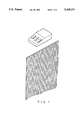
- the present invention relates to electro-optical mouses and relates more particularly to an electro-optical mouse which includes a light source to project light on a grid of lines on a reflective surface, a cylindrical lens to amplify the reflected image and send amplified signals corresponding to X-lines to a first detector and amplified signals corresponding to Y-lines to a second detector, and a microprocessor for processing, corresponding signals from said first and second detectors control the movement of a cursor associated with a visual display system.
- a mouse which is used to move or position the cursor or part of the display of a computer system is generally operated through mechanical transmission. It is generally comprised of a rolling ball disposed at the bottom and driven to rotate in a direction and amount corresponding to movement of a joy-stick and therefore, convert translational motion into a position signal for controlling the movement of the cursor or part of the display in a computer system.
- the main disadvantage of the mechanical mouse is its high error rate. Further, the rolling ball may wear off easily causing severe error.
- An electro-optical mouse generally comprises at least one light source to project light on a grid of lines on a reflective surface and at least one detector for interpreting the position of the housing thereof over the grid of lines. Translational motion of the housing is further converted into a position signal by a transducer for controlling the movement of the cursor.
- a single lens and a single detector may be used to detect light changes in X and Y directions through two ways.
- the lines on the grid are made with optically transmissive inks and are illuminated by a dual color monochromatic light source so that the moving direction of the housing can be effectively distinguished by the detector according to the wavelength of the reflected light.
- the X and Y directions are detected through different lenses, namely, the X lines are made on the top edge of the reflective surface while the Y lines are made on the bottom edge thereof and, separate lenses are provided at different focal distances for detecting the reflection from the X lines and the Y lines separately.
- the line crossings in the X direction may interfere with the line crossings in the Y direction to affect the accurate control of a cursor.
- the present invention is to utilize cylindrical lenses to amplify line crossings in the X and Y directions separately so that the changes contrast ratio can be more effectively sensed by the detectors and interference problems between X and Y line crossings can be eliminated.
- FIG. 1 is a schematic drawing showing the use of the present invention
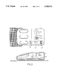
- FIG. 2 is a top view and a sectional side view of the preferred embodiment of the present invention.
- FIG. 3 is an electronic signal processing system chart according to the present invention.
- FIG. 4 illustrates the operation of the present invention
- FIG. 5 illustrates the manner in which line crossings in parallel with the central axis of the cylindrical lens are amplified.
- an electro-optical mouse in accordance with the present invention is generally comprised of housing 1, light source means, cylindrical lens means, reflector means and detector means.
- Housing 1 is provided to cover internal component parts, having a plurality of selector keys at the top for the selection of different functions, and X line signal and Y line signal pick-up devices at the inside which are disposed at right angles to each other.
- Light source means includes LEDs 21 and 22 which project light onto the grid of lines on a reflective surface.
- the cylindrical lens means includes a first cylindrical lens 31 disposed in a X direction and a second cylindrical lens 32 disposed in a Y direction to respectively amplify the image of X or Y lines obtained from the grid of lines on the reflective surface, i.e., each cylindrical lens 31 or 32 amplify only the line crossings which are in parallel with the central axis thereof (see FIG. 5).
- the detector means can efficiently precisely sense the changes in contrast ratio in X or Y direction and accurately generates electrical signals representing the line crossings.
- the reflector means includes a first reflector 41 (in the X direction) and a second reflector 42 (in the Y direction) respectively disposed between and above the cylindrical lens means and the detector means to reflect the light from the cylindrical lens means to the detector means.
- the detector means includes a first detector 51 to sense any reflected light signal from the first reflector 41 and a second detector 52 to sense any reflected light signal from the second reflector 42. While moving the mouse, the changes in contrast ratio are detected by the detectors 51 and 52 which, after through a logic operation, generate corresponding electric signals to a computer to accurately control the movement of a cursor.
Abstract
An electro-optical mouse includes two light sources to respectively project light onto a grid of lines on a reflective surface; two cylindrical lenses at right angles to each other to respectively amplify the X and Y line crossings; two detectors to respectively receive the output light signals from the two cylindrical lenses via two reflectors and, generate electrical signals according to the sensed changes in contrast ratio, in order to accurately control the movement of a cursor on the visual display of a computer.
Description
This application is a continuation of application Ser. No. 07/709,829 filed Jun. 4, 1991, now abandoned.
The present invention relates to electro-optical mouses and relates more particularly to an electro-optical mouse which includes a light source to project light on a grid of lines on a reflective surface, a cylindrical lens to amplify the reflected image and send amplified signals corresponding to X-lines to a first detector and amplified signals corresponding to Y-lines to a second detector, and a microprocessor for processing, corresponding signals from said first and second detectors control the movement of a cursor associated with a visual display system.
Conventionally, a mouse which is used to move or position the cursor or part of the display of a computer system is generally operated through mechanical transmission. It is generally comprised of a rolling ball disposed at the bottom and driven to rotate in a direction and amount corresponding to movement of a joy-stick and therefore, convert translational motion into a position signal for controlling the movement of the cursor or part of the display in a computer system. The main disadvantage of the mechanical mouse is its high error rate. Further, the rolling ball may wear off easily causing severe error.
Recently, electro-optical technology has been applied in manufacturing electro-optical mouses for controlling the movement of the cursor in a visual display more efficiently and accurately. An electro-optical mouse generally comprises at least one light source to project light on a grid of lines on a reflective surface and at least one detector for interpreting the position of the housing thereof over the grid of lines. Translational motion of the housing is further converted into a position signal by a transducer for controlling the movement of the cursor.
According to the known structures of electro-optical mouses, a single lens and a single detector may be used to detect light changes in X and Y directions through two ways. In a first way, the lines on the grid are made with optically transmissive inks and are illuminated by a dual color monochromatic light source so that the moving direction of the housing can be effectively distinguished by the detector according to the wavelength of the reflected light. In a second way, the X and Y directions,are detected through different lenses, namely, the X lines are made on the top edge of the reflective surface while the Y lines are made on the bottom edge thereof and, separate lenses are provided at different focal distances for detecting the reflection from the X lines and the Y lines separately. In the electro-optical mouses which utilize a single lens and single detector for X and Y detection, the line crossings in the X direction may interfere with the line crossings in the Y direction to affect the accurate control of a cursor. The present invention is to utilize cylindrical lenses to amplify line crossings in the X and Y directions separately so that the changes contrast ratio can be more effectively sensed by the detectors and interference problems between X and Y line crossings can be eliminated.
FIG. 1 is a schematic drawing showing the use of the present invention;
FIG. 2 is a top view and a sectional side view of the preferred embodiment of the present invention;
FIG. 3 is an electronic signal processing system chart according to the present invention;
FIG. 4 illustrates the operation of the present invention; and
FIG. 5 illustrates the manner in which line crossings in parallel with the central axis of the cylindrical lens are amplified.
Referring to the annexed drawings in greater detail, an electro-optical mouse in accordance with the present invention is generally comprised of housing 1, light source means, cylindrical lens means, reflector means and detector means.
Light source means includes LEDs 21 and 22 which project light onto the grid of lines on a reflective surface.
The cylindrical lens means includes a first cylindrical lens 31 disposed in a X direction and a second cylindrical lens 32 disposed in a Y direction to respectively amplify the image of X or Y lines obtained from the grid of lines on the reflective surface, i.e., each cylindrical lens 31 or 32 amplify only the line crossings which are in parallel with the central axis thereof (see FIG. 5). By means of the cylindrical lenses 31 and 32, the detector means can efficiently precisely sense the changes in contrast ratio in X or Y direction and accurately generates electrical signals representing the line crossings.
The reflector means includes a first reflector 41 (in the X direction) and a second reflector 42 (in the Y direction) respectively disposed between and above the cylindrical lens means and the detector means to reflect the light from the cylindrical lens means to the detector means.
The detector means includes a first detector 51 to sense any reflected light signal from the first reflector 41 and a second detector 52 to sense any reflected light signal from the second reflector 42. While moving the mouse, the changes in contrast ratio are detected by the detectors 51 and 52 which, after through a logic operation, generate corresponding electric signals to a computer to accurately control the movement of a cursor.
Claims (1)
1. An electro-optical mouse, comprising a first signal pick-up device for detecting, in an X direction, changes in contrast ratio of a reflective surface caused by passage of the first signal pick-up device over a grid of lines on the reflective surface in the X direction and second pick-up device for detecting, in a Y direction, changes in contrast ratio of the reflective surface caused by passage of the second signal pick-up device over said grid of lines in Y direction, said first and second signal pick-up devices comprising light source means including an LED light source for projecting light onto said reflective surface, lens means including a cylindrical lens for amplifying light reflected from said surface, reflector means including a reflector for transmitting light from said cylindrical lens to a detector, said detector including means for generating an electrical signal sensed changes in contrast ratio in order to enable a computer to accurately control the movement of a cursor on a visual display the central axes of said cylindrical lenses being oriented at right angles to each other to separately amplify changes in said contrast ratio on the X and Y direction each lens amplifying only the line crossing of said grid of lines which are disposed parallel to the central axis thereof.
Priority Applications (1)
| Application Number | Priority Date | Filing Date | Title |
|---|---|---|---|
| US08/022,384 US5349371A (en) | 1991-06-04 | 1993-02-24 | Electro-optical mouse with means to separately detect the changes in contrast ratio in X and Y directions |
Applications Claiming Priority (2)
| Application Number | Priority Date | Filing Date | Title |
|---|---|---|---|
| US70982991A | 1991-06-04 | 1991-06-04 | |
| US08/022,384 US5349371A (en) | 1991-06-04 | 1993-02-24 | Electro-optical mouse with means to separately detect the changes in contrast ratio in X and Y directions |
Related Parent Applications (1)
| Application Number | Title | Priority Date | Filing Date |
|---|---|---|---|
| US70982991A Continuation | 1991-06-04 | 1991-06-04 |
Publications (1)
| Publication Number | Publication Date |
|---|---|
| US5349371A true US5349371A (en) | 1994-09-20 |
Family
ID=24851457
Family Applications (1)
| Application Number | Title | Priority Date | Filing Date |
|---|---|---|---|
| US08/022,384 Expired - Fee Related US5349371A (en) | 1991-06-04 | 1993-02-24 | Electro-optical mouse with means to separately detect the changes in contrast ratio in X and Y directions |
Country Status (1)
| Country | Link |
|---|---|
| US (1) | US5349371A (en) |
Cited By (29)
| Publication number | Priority date | Publication date | Assignee | Title |
|---|---|---|---|---|
| US5907152A (en) * | 1992-10-05 | 1999-05-25 | Logitech, Inc. | Pointing device utilizing a photodetector array |
| US6078312A (en) * | 1997-07-09 | 2000-06-20 | Gateway 2000, Inc. | Pointing device with absolute and relative positioning capability |
| US6111563A (en) * | 1997-10-27 | 2000-08-29 | Hines; Stephen P. | Cordless retroreflective optical computer mouse |
| US6172354B1 (en) | 1998-01-28 | 2001-01-09 | Microsoft Corporation | Operator input device |
| US6303924B1 (en) | 1998-12-21 | 2001-10-16 | Microsoft Corporation | Image sensing operator input device |
| US20010043191A1 (en) * | 1997-07-31 | 2001-11-22 | Todd D. Lindsey | Audio and video controls on a pointing device for a computer |
| US6344846B1 (en) | 1997-10-27 | 2002-02-05 | Stephen P. Hines | Optical retroreflective remote control |
| US20020030669A1 (en) * | 2000-09-12 | 2002-03-14 | Nec Corporation | Optical pointing device, control method thereof and computer program product recording the same |
| US20020084986A1 (en) * | 2001-01-04 | 2002-07-04 | Armstrong Brad A. | Computer mouse with specialized button(s) |
| US20020190953A1 (en) * | 1998-03-30 | 2002-12-19 | Agilent Technologies, Inc. | Seeing eye mouse for a computer system |
| US20030025671A1 (en) * | 2001-08-02 | 2003-02-06 | Yu-Chih Cheng | Optical mouse with a roller ball |
| US6529184B1 (en) | 2000-03-22 | 2003-03-04 | Microsoft Corporation | Ball pattern architecture |
| US6531692B1 (en) | 1999-03-22 | 2003-03-11 | Microsoft Corporation | Optical coupling assembly for image sensing operator input device |
| US20040042232A1 (en) * | 2002-09-02 | 2004-03-04 | Chien-Chang Huang | Optical apparatus |
| US6816150B2 (en) * | 2001-09-07 | 2004-11-09 | Microsoft Corporation | Data input device power management including beacon state |
| US20050135659A1 (en) * | 2003-12-19 | 2005-06-23 | Smith John D. | Optical motion sensor |
| US20050141068A1 (en) * | 2003-12-31 | 2005-06-30 | Debenedictis Leonard C. | High speed, high efficiency optical pattern generator using rotating optical elements |
| US20050154380A1 (en) * | 2003-12-23 | 2005-07-14 | Debenedictis Leonard C. | Method and apparatus for monitoring and controlling laser-induced tissue treatment |
| US20050186710A1 (en) * | 2004-02-23 | 2005-08-25 | Moyer Vincent C. | Integrated circuit package provided with cooperatively arranged illumination and sensing capabilities |
| US20050259306A1 (en) * | 2003-12-31 | 2005-11-24 | Broome Barry G | Two-dimensional optical scan system using a counter-rotating disk scanner |
| US7006075B1 (en) | 1997-11-10 | 2006-02-28 | Micron Technology Inc. | Ergonomic computer mouse |
| GB2424271A (en) * | 2005-03-18 | 2006-09-20 | Agilent Technologies Inc | Optical navigation system |
| US20060232556A1 (en) * | 2005-04-13 | 2006-10-19 | Mao-Hsiung Chien | Lens module for optical mouse and related optical module and computer input apparatus |
| US20070197290A1 (en) * | 2003-09-18 | 2007-08-23 | Ssd Company Limited | Music Game Device, Music Game System, Operation Object, Music Game Program, And Music Game Method |
| US20090159780A1 (en) * | 2007-12-19 | 2009-06-25 | Avago Technologies Ecbu Ip (Singapore) Pte. Ltd. | Optical navigation apparatus and method for making the apparatus |
| US8674932B2 (en) | 1996-07-05 | 2014-03-18 | Anascape, Ltd. | Image controller |
| CN104699325A (en) * | 2013-12-09 | 2015-06-10 | 原相科技股份有限公司 | Optical navigation system suitable for ambient light and detection starting and detection method of optical navigation system |
| US9081426B2 (en) | 1992-03-05 | 2015-07-14 | Anascape, Ltd. | Image controller |
| US9703396B2 (en) * | 2013-07-12 | 2017-07-11 | Wen-Chieh Geoffrey Lee | High resolution and high sensitivity three-dimensional (3D) cursor maneuvering reference plane, and methods of its manufacture |
Citations (5)
| Publication number | Priority date | Publication date | Assignee | Title |
|---|---|---|---|---|
| US4390873A (en) * | 1981-05-18 | 1983-06-28 | Kirsch Steven T | Electronic mouse |
| JPS619720A (en) * | 1984-06-25 | 1986-01-17 | Nisshin Koki Kk | Optical mouse |
| US4647771A (en) * | 1983-12-05 | 1987-03-03 | Nissin Kohki Co. Ltd. | Optical mouse with X and Y line patterns on separate planes |
| US4880968A (en) * | 1988-01-14 | 1989-11-14 | Kwang Chien Fong | Optical input cursor device using optical grid means |
| US4935619A (en) * | 1988-04-29 | 1990-06-19 | Deutsche Itt Industries Gmbh | Wireless remote-control system for electronic apparatus |
-
1993
- 1993-02-24 US US08/022,384 patent/US5349371A/en not_active Expired - Fee Related
Patent Citations (5)
| Publication number | Priority date | Publication date | Assignee | Title |
|---|---|---|---|---|
| US4390873A (en) * | 1981-05-18 | 1983-06-28 | Kirsch Steven T | Electronic mouse |
| US4647771A (en) * | 1983-12-05 | 1987-03-03 | Nissin Kohki Co. Ltd. | Optical mouse with X and Y line patterns on separate planes |
| JPS619720A (en) * | 1984-06-25 | 1986-01-17 | Nisshin Koki Kk | Optical mouse |
| US4880968A (en) * | 1988-01-14 | 1989-11-14 | Kwang Chien Fong | Optical input cursor device using optical grid means |
| US4935619A (en) * | 1988-04-29 | 1990-06-19 | Deutsche Itt Industries Gmbh | Wireless remote-control system for electronic apparatus |
Cited By (66)
| Publication number | Priority date | Publication date | Assignee | Title |
|---|---|---|---|---|
| US9081426B2 (en) | 1992-03-05 | 2015-07-14 | Anascape, Ltd. | Image controller |
| US5907152A (en) * | 1992-10-05 | 1999-05-25 | Logitech, Inc. | Pointing device utilizing a photodetector array |
| US20110141022A1 (en) * | 1995-10-06 | 2011-06-16 | Avago Technologies Ecbu Ip (Singapore) Pte. Ltd. | Method and arrangement for tracking movement relative to a surface |
| US20070103439A1 (en) * | 1995-10-06 | 2007-05-10 | Avago Technologies, Ltd. | Method of operating an optical mouse |
| US20080055243A1 (en) * | 1995-10-06 | 2008-03-06 | Gordon Gary B | Method of operating an optical mouse |
| US20080048983A1 (en) * | 1995-10-06 | 2008-02-28 | Gordon Gary B | Method of operating an optical mouse |
| US20050231484A1 (en) * | 1995-10-06 | 2005-10-20 | Agilent Technologies, Inc. | Optical mouse with uniform level detection method |
| US8350812B2 (en) | 1995-10-06 | 2013-01-08 | Pixart Imaging Inc. | Method and arrangement for tracking movement relative to a surface |
| US7791590B1 (en) | 1995-10-06 | 2010-09-07 | Avago Technologies Ecbu Ip (Singapore) Pte. Ltd. | Optical mouse with uniform level detection |
| US8212778B2 (en) | 1995-10-06 | 2012-07-03 | Avago Technologies Ecbu Ip (Singapore) Pte. Ltd. | Imaging and navigation arrangement for controlling a cursor |
| US7800585B2 (en) | 1995-10-06 | 2010-09-21 | Avago Technologies Ecbu Ip (Singapore) Pte. Ltd. | Method of operating an optical mouse |
| US7808485B2 (en) | 1995-10-06 | 2010-10-05 | Avago Technologies Ecbu Ip (Singapore) Pte. Ltd. | Method of operating an optical mouse |
| US7907120B2 (en) | 1995-10-06 | 2011-03-15 | Avago Technologies Ecbu Ip (Singapore) Pte. Ltd. | Optical mouse with uniform level detection method |
| US8674932B2 (en) | 1996-07-05 | 2014-03-18 | Anascape, Ltd. | Image controller |
| US6078312A (en) * | 1997-07-09 | 2000-06-20 | Gateway 2000, Inc. | Pointing device with absolute and relative positioning capability |
| US7079112B1 (en) | 1997-07-09 | 2006-07-18 | Gateway Inc. | Pointing device with absolute and relative positioning capability |
| US20010043191A1 (en) * | 1997-07-31 | 2001-11-22 | Todd D. Lindsey | Audio and video controls on a pointing device for a computer |
| US6344846B1 (en) | 1997-10-27 | 2002-02-05 | Stephen P. Hines | Optical retroreflective remote control |
| US6111563A (en) * | 1997-10-27 | 2000-08-29 | Hines; Stephen P. | Cordless retroreflective optical computer mouse |
| US20060139331A1 (en) * | 1997-11-10 | 2006-06-29 | Joshua Olson | Ergonomic computer mouse |
| US7701443B2 (en) | 1997-11-10 | 2010-04-20 | Micron Technology, Inc. | Ergonomic computer mouse |
| US7006075B1 (en) | 1997-11-10 | 2006-02-28 | Micron Technology Inc. | Ergonomic computer mouse |
| US6172354B1 (en) | 1998-01-28 | 2001-01-09 | Microsoft Corporation | Operator input device |
| US20020190953A1 (en) * | 1998-03-30 | 2002-12-19 | Agilent Technologies, Inc. | Seeing eye mouse for a computer system |
| US6950094B2 (en) | 1998-03-30 | 2005-09-27 | Agilent Technologies, Inc | Seeing eye mouse for a computer system |
| US6303924B1 (en) | 1998-12-21 | 2001-10-16 | Microsoft Corporation | Image sensing operator input device |
| US6373047B1 (en) | 1998-12-21 | 2002-04-16 | Microsoft Corp | Image sensing operator input device |
| CN1331029C (en) * | 1999-03-22 | 2007-08-08 | 微软公司 | Optical coupling assembly for image sensing operator input device |
| US6531692B1 (en) | 1999-03-22 | 2003-03-11 | Microsoft Corporation | Optical coupling assembly for image sensing operator input device |
| US6529184B1 (en) | 2000-03-22 | 2003-03-04 | Microsoft Corporation | Ball pattern architecture |
| US6781572B2 (en) * | 2000-09-12 | 2004-08-24 | Nec Corporation | Optical pointing device, control method thereof and computer program product recording the same |
| US20020030669A1 (en) * | 2000-09-12 | 2002-03-14 | Nec Corporation | Optical pointing device, control method thereof and computer program product recording the same |
| US20020084986A1 (en) * | 2001-01-04 | 2002-07-04 | Armstrong Brad A. | Computer mouse with specialized button(s) |
| US20030025671A1 (en) * | 2001-08-02 | 2003-02-06 | Yu-Chih Cheng | Optical mouse with a roller ball |
| US7023425B2 (en) | 2001-09-07 | 2006-04-04 | Microsoft Corporation | Data input device power management including beacon state |
| US20050078085A1 (en) * | 2001-09-07 | 2005-04-14 | Microsoft Corporation | Data input device power management including beacon state |
| US6816150B2 (en) * | 2001-09-07 | 2004-11-09 | Microsoft Corporation | Data input device power management including beacon state |
| US7050043B2 (en) | 2002-09-02 | 2006-05-23 | Pixart Imagning Inc. | Optical apparatus |
| US20040042232A1 (en) * | 2002-09-02 | 2004-03-04 | Chien-Chang Huang | Optical apparatus |
| US20070197290A1 (en) * | 2003-09-18 | 2007-08-23 | Ssd Company Limited | Music Game Device, Music Game System, Operation Object, Music Game Program, And Music Game Method |
| US20050135659A1 (en) * | 2003-12-19 | 2005-06-23 | Smith John D. | Optical motion sensor |
| US7282060B2 (en) | 2003-12-23 | 2007-10-16 | Reliant Technologies, Inc. | Method and apparatus for monitoring and controlling laser-induced tissue treatment |
| US20050154380A1 (en) * | 2003-12-23 | 2005-07-14 | Debenedictis Leonard C. | Method and apparatus for monitoring and controlling laser-induced tissue treatment |
| US20080068694A1 (en) * | 2003-12-31 | 2008-03-20 | Reliant Technologies, Inc. | High speed, high efficiency optical pattern generator using rotating optical elements |
| US7411711B2 (en) | 2003-12-31 | 2008-08-12 | Reliant Technologies, Inc. | High speed, high efficiency optical pattern generator using rotating optical elements |
| US7196831B2 (en) | 2003-12-31 | 2007-03-27 | Reliant Technologies, Inc. | Two-dimensional optical scan system using a counter-rotating disk scanner |
| US7480086B2 (en) | 2003-12-31 | 2009-01-20 | Reliant Technologies, Inc. | High speed, high efficiency optical pattern generator using rotating optical elements |
| US7184184B2 (en) | 2003-12-31 | 2007-02-27 | Reliant Technologies, Inc. | High speed, high efficiency optical pattern generator using rotating optical elements |
| US20050141068A1 (en) * | 2003-12-31 | 2005-06-30 | Debenedictis Leonard C. | High speed, high efficiency optical pattern generator using rotating optical elements |
| US7636186B2 (en) | 2003-12-31 | 2009-12-22 | Reliant Technologies, Inc. | High speed, high efficiency optical pattern generator using rotating optical elements |
| US20050259306A1 (en) * | 2003-12-31 | 2005-11-24 | Broome Barry G | Two-dimensional optical scan system using a counter-rotating disk scanner |
| US7675073B2 (en) | 2004-02-23 | 2010-03-09 | Avago Technologies Ecbu Ip (Singapore) Pte. Ltd. | Integrated circuit package provided with cooperatively arranged illumination and sensing capabilities |
| US20050186710A1 (en) * | 2004-02-23 | 2005-08-25 | Moyer Vincent C. | Integrated circuit package provided with cooperatively arranged illumination and sensing capabilities |
| US7148078B2 (en) * | 2004-02-23 | 2006-12-12 | Avago Technologies Egbu Ip (Singapore) Pte. Ltd. | Integrated circuit package provided with cooperatively arranged illumination and sensing capabilities |
| US20080283847A1 (en) * | 2004-02-23 | 2008-11-20 | Moyer Vincent C | Integrated circuit package provided with cooperatively arranged illumination and sensing capabilities |
| US20060209015A1 (en) * | 2005-03-18 | 2006-09-21 | Feldmeier David C | Optical navigation system |
| GB2424271A (en) * | 2005-03-18 | 2006-09-20 | Agilent Technologies Inc | Optical navigation system |
| CN1834878B (en) * | 2005-03-18 | 2010-05-12 | 安华高科技杰纳勒尔Ip(新加坡)私人有限公司 | Optical navigation system |
| US20060232556A1 (en) * | 2005-04-13 | 2006-10-19 | Mao-Hsiung Chien | Lens module for optical mouse and related optical module and computer input apparatus |
| US20090159780A1 (en) * | 2007-12-19 | 2009-06-25 | Avago Technologies Ecbu Ip (Singapore) Pte. Ltd. | Optical navigation apparatus and method for making the apparatus |
| US7615733B2 (en) * | 2007-12-19 | 2009-11-10 | Avago Technologies Ecbu Ip (Singapore) Pte. Ltd. | Optical navigation apparatus and method for making the apparatus |
| US9703396B2 (en) * | 2013-07-12 | 2017-07-11 | Wen-Chieh Geoffrey Lee | High resolution and high sensitivity three-dimensional (3D) cursor maneuvering reference plane, and methods of its manufacture |
| US10635190B2 (en) * | 2013-07-12 | 2020-04-28 | Wen-Chieh Geoffrey Lee | High resolution and high sensitivity three-dimensional (3D) cursor maneuvering reference plane, and methods of its manufacture |
| US11531408B2 (en) * | 2013-07-12 | 2022-12-20 | Wen-Chieh Geoffrey Lee | High resolution and high sensitivity three-dimensional (3D) cursor maneuvering reference plane, and method of its manufacture |
| CN104699325A (en) * | 2013-12-09 | 2015-06-10 | 原相科技股份有限公司 | Optical navigation system suitable for ambient light and detection starting and detection method of optical navigation system |
| CN104699325B (en) * | 2013-12-09 | 2018-03-30 | 原相科技股份有限公司 | Suitable for ambient light and the optical navigation system and its detection method that lift detection |
Similar Documents
| Publication | Publication Date | Title |
|---|---|---|
| US5349371A (en) | Electro-optical mouse with means to separately detect the changes in contrast ratio in X and Y directions | |
| US5517211A (en) | Optical signal detector for an electro-optical mouse | |
| US6618038B1 (en) | Pointing device having rotational sensing mechanisms | |
| US6741234B2 (en) | Optical mouse using a total reflection prism | |
| JP5166713B2 (en) | Position detection system using laser speckle | |
| US7432893B2 (en) | Input device based on frustrated total internal reflection | |
| US5051736A (en) | Optical stylus and passive digitizing tablet data input system | |
| US5786810A (en) | Method of determining an object's position and associated apparatus | |
| US20020080117A1 (en) | Optical mouse | |
| KR100399635B1 (en) | Optical mouse | |
| JPH0510615B2 (en) | ||
| US20060279545A1 (en) | Sensor chip for laser optical mouse and related laser optical mouse | |
| US7595478B2 (en) | Method and device for processing optical signals in computer mouse | |
| US20120274765A1 (en) | Apparatus for determining the location of a pointer within a region of interest | |
| US20040113886A1 (en) | Sensing structure for optic input | |
| US6307535B1 (en) | Pointing device for use in a computer system | |
| US20060125792A1 (en) | Input device adapted for a variety of surfaces of different reflective natures | |
| US20070242277A1 (en) | Optical navigation in relation to transparent objects | |
| US20080317471A1 (en) | Apparatus and system for remote control | |
| US7399955B2 (en) | Low profile optical navigation sensor | |
| US8330721B2 (en) | Optical navigation device with phase grating for beam steering | |
| US20050001818A1 (en) | Optic mouse | |
| US20040080495A1 (en) | Optical image detectors and navigation devices employing the same | |
| TW411416B (en) | Sensing apparatus | |
| US20070229461A1 (en) | Optical mouse that automatically adapts to glass surfaces and method of using the same |
Legal Events
| Date | Code | Title | Description |
|---|---|---|---|
| REMI | Maintenance fee reminder mailed | ||
| LAPS | Lapse for failure to pay maintenance fees | ||
| FP | Lapsed due to failure to pay maintenance fee |
Effective date: 19980920 |
|
| STCH | Information on status: patent discontinuation |
Free format text: PATENT EXPIRED DUE TO NONPAYMENT OF MAINTENANCE FEES UNDER 37 CFR 1.362 |