US5345443A - Network-based digital bandwidth-on-demand - Google Patents
Network-based digital bandwidth-on-demand Download PDFInfo
- Publication number
- US5345443A US5345443A US07/876,556 US87655692A US5345443A US 5345443 A US5345443 A US 5345443A US 87655692 A US87655692 A US 87655692A US 5345443 A US5345443 A US 5345443A
- Authority
- US
- United States
- Prior art keywords
- switch
- network
- serving
- digital channel
- listings
- Prior art date
- Legal status (The legal status is an assumption and is not a legal conclusion. Google has not performed a legal analysis and makes no representation as to the accuracy of the status listed.)
- Expired - Fee Related
Links
Images


Classifications
-
- H—ELECTRICITY
- H04—ELECTRIC COMMUNICATION TECHNIQUE
- H04Q—SELECTING
- H04Q11/00—Selecting arrangements for multiplex systems
- H04Q11/04—Selecting arrangements for multiplex systems for time-division multiplexing
- H04Q11/0428—Integrated services digital network, i.e. systems for transmission of different types of digitised signals, e.g. speech, data, telecentral, television signals
-
- H—ELECTRICITY
- H04—ELECTRIC COMMUNICATION TECHNIQUE
- H04L—TRANSMISSION OF DIGITAL INFORMATION, e.g. TELEGRAPHIC COMMUNICATION
- H04L45/00—Routing or path finding of packets in data switching networks
- H04L45/02—Topology update or discovery
- H04L45/10—Routing in connection-oriented networks, e.g. X.25 or ATM
-
- H—ELECTRICITY
- H04—ELECTRIC COMMUNICATION TECHNIQUE
- H04L—TRANSMISSION OF DIGITAL INFORMATION, e.g. TELEGRAPHIC COMMUNICATION
- H04L45/00—Routing or path finding of packets in data switching networks
- H04L45/24—Multipath
-
- H—ELECTRICITY
- H04—ELECTRIC COMMUNICATION TECHNIQUE
- H04Q—SELECTING
- H04Q2213/00—Indexing scheme relating to selecting arrangements in general and for multiplex systems
- H04Q2213/13103—Memory
-
- H—ELECTRICITY
- H04—ELECTRIC COMMUNICATION TECHNIQUE
- H04Q—SELECTING
- H04Q2213/00—Indexing scheme relating to selecting arrangements in general and for multiplex systems
- H04Q2213/13106—Microprocessor, CPU
-
- H—ELECTRICITY
- H04—ELECTRIC COMMUNICATION TECHNIQUE
- H04Q—SELECTING
- H04Q2213/00—Indexing scheme relating to selecting arrangements in general and for multiplex systems
- H04Q2213/13208—Inverse multiplexing, channel bonding, e.g. TSSI aspects
-
- H—ELECTRICITY
- H04—ELECTRIC COMMUNICATION TECHNIQUE
- H04Q—SELECTING
- H04Q2213/00—Indexing scheme relating to selecting arrangements in general and for multiplex systems
- H04Q2213/13209—ISDN
-
- H—ELECTRICITY
- H04—ELECTRIC COMMUNICATION TECHNIQUE
- H04Q—SELECTING
- H04Q2213/00—Indexing scheme relating to selecting arrangements in general and for multiplex systems
- H04Q2213/13292—Time division multiplexing, TDM
-
- H—ELECTRICITY
- H04—ELECTRIC COMMUNICATION TECHNIQUE
- H04Q—SELECTING
- H04Q2213/00—Indexing scheme relating to selecting arrangements in general and for multiplex systems
- H04Q2213/1331—Delay elements, shift registers
-
- H—ELECTRICITY
- H04—ELECTRIC COMMUNICATION TECHNIQUE
- H04Q—SELECTING
- H04Q2213/00—Indexing scheme relating to selecting arrangements in general and for multiplex systems
- H04Q2213/13332—Broadband, CATV, dynamic bandwidth allocation
-
- H—ELECTRICITY
- H04—ELECTRIC COMMUNICATION TECHNIQUE
- H04Q—SELECTING
- H04Q2213/00—Indexing scheme relating to selecting arrangements in general and for multiplex systems
- H04Q2213/1336—Synchronisation
Definitions
- the invention relates to digital transmission systems and, more particularly, to the transmission of digital information via multiple telecommunication channels.
- Switched digital service (“SDS”) telecommunication channels typically have either a 56 or 64 kilobit per second (“kb/s”) data rate capacity. This data capacity being determined by the particular environment in which the channel is employed: a standard SDS network, or an Integrated Services Digital Network (“ISDN").
- ISDN Integrated Services Digital Network
- One method of performing data transmissions over a public telecommunication network at rates beyond the standard digital channel capacity is to simultaneously establish connections over multiple SDS channels. For example, if a sender wished to transmit data at a rate N times the standard digital channel data rate, it would be necessary to dial N telephone numbers, whereby establishing the N individual channel connections to N separate receivers on the premises of the intended recipient.
- the recipient of the multiple calls must introduce a specific delay to each individual channel in order to synchronize the incoming signals. This compensation requires additional on-premises equipment, and a time consuming calibration process to determine the relative path delays among the channels.
- An alternative to the communication method described above is to effect the multiple digital channel connections over a network configured so as to guarantee identical path lengths for all of the channels involve. While the capability to selectively restrict multiple digital channel connections to the same transmission path is available within some specialized telecommunication networks, most public telecommunication networks do not offer this function. Furthermore, reconfiguring existing network switches so that they are capable of securing, on-demand, multiple digital channel connections having equal path lengths would be quite costly, requiring a significant investment of both equipment and engineering.
- tandem switch As it serves to link two other network switches
- tandem switch As it serves to link two other network switches
- multiple digital channel connections having equal path lengths cannot be reliably secured. This is due to the likelihood that the routing of all the channel connections involved would not be effected via the same network switches or facility routes outside of the tandem switch.
- a method for effecting on-demand, multiple digital channel connections between network subscribers, wherein each of a series of call requests from a given network subscriber to a given recipient establishes a connection via a restricted tandem switching arrangement.
- the switches within the network facilitating this method are each programmed to utilize inter-switch paths having essentially equivalent electrical delays when effecting connections for calls dialed by network subscribers designated as bandwidth-on-demand users.
- This restricted switching insures an equivalent delay is introduced to each of the multiple channels, a channel demultiplexer at the sending location, and a channel multiplexer at the receiving location (both capable of accommodating the proper number of individual digital channels), are the only special on-premises equipment which the sender and receiver need have to transfer data.
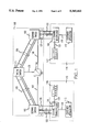
- FIG. 1 shows, in simplified block diagram form, an ISDN telecommunication system which facilitates the practice of a method of the invention
- FIG. 2 shows, in simplified block diagram form, the internal architecture of the switches of FIG. 1;
- FIG. 3 shows, in simplified block diagram form, an ISDN telecommunication system which facilitates the practice of a second method of the invention
- FIG. 4 shows, in simplified block diagram form, an SDS telecommunication system which facilitates the practice of a method of the invention.
- FIG. 5 shows, in simplified block diagram form, an SDS telecommunication system which facilitates the practice of yet another method of the invention.
- FIG. 1 shows, in simplified form, a public ISDN telecommunication system which facilitates the practice of a particular method of the invention.
- ISDN 100 having a restricted tandem switching architecture.
- ISDN 100 consists of tandem switch 101, serving switches 102 and 103, and Signaling System 7 ("SS7") 104 (an internationally established standard signaling arrangement).
- SS7 Signaling System 7
- Each serving switch may be selectively linked to tandem switch 101 via multiple T1 digital lines; each T1 line supports a DS1 digital signal containing 24 individual DS0 channels.
- T1 digital lines For purposes of illustration, only two T1 lines are depicted, 105 and 106, and only three of the 24 DS0 channels supported within each of these lines are explicitly shown.
- SS7 104 is linked to tandem switch 101 and serving switches 102 and 103 by digital communication lines 107, 108 and 109.
- the serving and tandem switches in the above described network are each electronic switching systems having the basic architecture illustrated in FIG. 2. As shown, contained within each electronic switching system are the following components: incoming trunk interface 201, outgoing trunk interface 202, switching circuitry 203, processor 204, and memory 205. Such electronic switching systems are known and commercially available. Stored within memory 205 is an address listing of viable outgoing trunks through which the switch may effect connections. For the serving switches contained within the tandem network, these lists contain the addresses of trunks linking the serving switch and the tandem switch. The trunk listings stored within serving switch memory 205 are arranged into separate groups (206). One of these groups, designated the restricted subscriber domain, contains only the addresses of trunks having practically identical path lengths.
- the serving switch is programmed to restrict the routing of DS0 calls placed by designated network subscribers to paths having addresses listed within the restricted subscriber domain (i.e., paths having comparable delay characteristics). These paths need not be contained within the same T1 line.
- the designated bandwidth-on-demand subscribers (“BOD subscribers”) would have notified the network provider that they wished to be identified as a user of bandwidth-on-demand capabilities.
- Programming a switch to route calls received from a particular group of subscribers is well known in the art, and the individual connections to the tandem switch are effected in a known fashion.
- the memory of tandem switch 101 contains similarly grouped address listing of trunks capable of providing connections to serving switches.
- tandem switch 101 is programmed to restrict the routing of calls originated by BOD subscribers to paths within a grouping of trunk lines having virtually identical path lengths.
- CPE 110 Customer Premises Equipment
- CPE 110 is configured to transmit data over ISDN 100 at a fixed data rate of N ⁇ 64 kb/s; N being is a fixed integer value between 2 and 23 (inclusive).
- This CPE is located on the premises of a first BOD subscriber.
- CPE 110 consists of customer application 112, channel demultiplexer (“DEMUX”) 114, and a D-Channel controller (“DCC”) 116.
- Customer application 112 is linked to DEMUX 114 via high-rate data connection 118.
- DEMUX 114 may be selectively linked to serving switch 102 via Primary Rate Interface (“PRI") 120.
- PRI 120 provides a 23 channel DS0 connection (labeled 122) to DEMUX 114, as well as a D-Channel signaling connection (labeled 124) to DCC 116.
- CPE 111 Customer Premises Equipment 111 is also shown in FIG. 1. This CPE is located on the premises of a second BOD subscriber, and is configured to receive N separate DS0 signals via ISDN 100. Customer application 113 is linked to channel multiplexer ("MUX") 115 via high-rate data connection 119. MUX 115 may be selectively linked to serving switch 103 via PRI 121. PRI 121 provides 23-channel DS0 connection 123 to MUX 115, and D-Channel signaling connection 125 to DCC 117.
- MUX channel multiplexer
- the first BOD subscriber initiates a multiple DS0 channel connection by employing DCC 116 to transmit a D-Channel signaling protocol SETUP message to serving switch 102 via D-Channel signaling connection 124.
- This protocol SETUP message which is transmitted within ISDN 100 via SS7 104 and digital communication lines 107, 108 and 109, attempts to establish a single DS0 channel connection between sending CPE 110 and receiving CPE 111.
- the call will be established via a path traversing serving switch 102, tandem switch 101, and serving switch 103. If a path along this facility route is available, a single DS0 channel connection is established.
- DCC 116 then sequentially initiates (N-1) additional calls to (N-1) individual telephone numbers associated with CPE 111.
- Each of these additional calls is routed by serving switch 102 and tandem switch 101 over DS0 channels supported by trunks having addresses stored within the subscriber domain listings of the switches. This insures that these additional connections are established over paths having delay characteristics almost identical to that of the initially established connection.
- CPE 111 answers the calls in sequential order, thereby building up the required N ⁇ DS0 bandwidth.
- the first BOD subscriber CPE transmits data at a rate of N ⁇ 64 kb/s from customer application 112 to DEMUX 114.
- DEMUX 114 separates the N ⁇ 64 kb/s rate data into N separate 64 kb/s data signals, and simultaneously transmits each of these 64 kb/s data signals over one of the N DS0 connections established between CPE 110 and CPE 111.
- MUX 115 of CPE 111 receives the N 64 kb/s data signals, reconstitutes the original N ⁇ 64 kb/s data signal, and transmits it, via high-rate data connection 119, to customer application 113.
- the above described method provides a practical method for effecting multiple DS0 channel connections.
- the network to which this method is applied is a public network
- actually obtaining a multiple DS0 channel connection may require more than one attempt. If, for example, any of the switches engaged in facilitating an N ⁇ DS0 transmission attempt have less than N channels available at the time of the attempt, the proper DS0 connections cannot be established between CPE 110 and CPE 111. When this condition exists, a "busy" message is sent to DCC 116, via a D-Channel message, and CPE 110 aborts the attempt to establish an N ⁇ DS0 connection. Another attempt to establish the connection may be initiated by CPE 110 immediately thereafter.
- FIG. 3 Another method of the invention may be practiced on ISDN system illustrated in FIG. 3.
- This system is similar to the system of FIG. 1, however CPE 310 and customer application 312 are configured to have the capability to transmit data at different selectable discrete rates, dependent upon the specific application.
- the particular transmission rate being I ⁇ 64 kb/s, where I is an integer between 2 and 23 (inclusive).
- CPE 311 and customer application 313 are configured to have the capability of receiving data at different selectable discrete rates, dependent upon the specific application; the particular reception rate being an integer multiple of 64 kb/s, not exceeding 1472 kb/s (23 ⁇ 64 kb/s).
- the serving and tandem switches operate in a fashion identical to that of the previously described embodiment.
- a multiple DS0 channel connection is initiated by the first BOD subscriber from CPE 310 by generating a D-Channel signaling protocol SETUP message via DCC 116.
- This protocol SETUP message is generated, transmitted, and responded to by network 100 in a fashion identical to that described in the previous method. If a path along the restricted facility route is available, a single DS0 channel connection is established.
- CPE 310 then sequentially initiates (I-1) additional calls to (I-1) individual telephone numbers associated with CPE 311; thereby establishing a sufficient number of DS0 channel connections to support the desired transmission bandwidth.
- each of these connections is established over DS0 channels supported by trunks having addresses stored within the subscriber domain listings of the serving and tandem switches. This insures that these additional connections are established over paths having delay characteristics almost identical to that of the initially established connection.
- CPE 311 sequentially answers the incoming calls, however, CPE 311 is not configured to receive a data signal of a particular fixed bandwidth, and receives no information via SS7 104 as to the total number of DS0 channel connections which will constitute any given multiple DS0 call. To insure that data transmission is not attempted until the correct I times DS0 bandwidth connection has been established, CPE 311 is adapted to enter a waiting state for a predetermined interval (nominally 15 seconds) after the reception of any individual DS0 call.
- the individual calls dialed to build-up the desired bandwidth need not be restricted to calls which establish a single DS0 channel connection.
- Present ISDN systems offer options to subscribers which allow synchronous data transmission at 384 kb/s to be facilitated by making one call (establishing what is referred to as an "H0" channel connection). This option may be incorporated into the disclosed invention, thereby allowing a 768 kb/s bandwidth connection to be obtained by sequentially dialing two 384 kb/s calls (as opposed to twelve single DS0 calls).
- 384 kb/s and 64 kb/s calls may be used in conjunction so as to reduce the number of calls that need be placed to establish other desired bandwidths.
- the application of this invention to ISDN systems need not be limited to simultaneously transmitting data via a maximum of 23 individual DS0 channel connections.
- the 23 DS0 channel connection limitation was mentioned in the above examples merely because the illustrated subscriber CPEs were each shown to be serviced by a single PRI.
- a single PRI only provides 23 DS0 channels.
- the method of the invention may be applied to any number of DS0 channel connections, limited only by the capabilities of the particular network and CPEs being employed.
- FIG. 4 shows, in simplified form, a public SDS telecommunication system which facilitates the practice of a particular method of the invention.
- SDS network 400 having a tandem switching architecture.
- SDS network 400 consists of tandem switch 401, and serving switches 402 and 403.
- the serving switches may each be selectively linked to tandem switch 401 via multiple T1 digital lines; each T1 line supporting a DS1 digital signal containing 24 individual DS0 channels.
- the serving and tandem switches of FIG. 4 are each electronic switching systems having the same basic architecture and memory configuration as the switch illustrated in FIG. 2.
- DS0 channel connections initiated by a BOD subscriber are effected via inter-switch paths having virtually the same delay. These paths need not be contained within the same T1 line.
- CPE 410 is located on the premises of a first BOD subscriber, and configured to transmit data over network 400 at a fixed data rate of N ⁇ 56 kb/s; where N is a fixed integer value between 2 and 24 (inclusive).
- CPE 410 consists of customer application 412, DEMUX 414, and controller 416.
- Customer application 412 is linked to DEMUX 414 via high-rate data connection 418.
- DEMUX 414 may be selectively linked to serving switch 402 via 24 individual DS0 channels (collectively designated service connection 422).
- Controller 416 governs the access of DS0 channels by DEMUX 414.
- CPE 411 is located on the premises of a second BOD subscriber, and is configured to receive N separate DS0 signals via ISDN 400.
- Customer application 413 is linked to MUX 415 via high-rate data connection 419.
- MUX 415 may be selectively linked to serving switch 403 via 24 individual DS0 (collectively designated service connection 423). Access to these DS0 channels by MUX 415 is governed by controller 417.
- a multiple DS0 channel connection is established by the first BOD subscriber by sequentially dialing N telephone numbers from CPE 410.
- Each of the dialed numbers is associated with a receiving port on MUX 415. This dialing is initiated by controller 416 via DEMUX 414.
- the dialed numbers may be N different telephone numbers, or the same number repeatedly dialed so as to access N lines within a hunt group associated with MUX 415.
- Each of these additional calls is routed by serving switch 102 and tandem switch 101 over DS0 channels supported by trunks having addresses stored within the subscriber domain listings of the switches. This insures that these additional connections are established over paths having delay characteristics almost identical to that of the initially established connection.
- CPE 411 answers incoming the calls in sequential order, thereby building up the required N ⁇ DS0 bandwidth.
- CPE 410 transmits data at a rate of N ⁇ 56 kb/s from customer application 412 to DEMUX 414.
- DEMUX 414 separates the N ⁇ 56 kb/s rate data into N separate 56 kb/s data signals, and simultaneously transmits each of these 56 kb/s data signals over one of the N connections established between CPE 410 and CPE 411.
- MUX 415 of CPE 411 receives the N 56 kb/s data signals, reconstitutes the original N ⁇ 56 kb/s data signal, and transmits it, via high-rate data connection 419, to customer application 413.
- Yet another method of the invention may be practiced on the SDS telecommunications system illustrated in FIG. 5.
- This system is similar to the system of FIG. 4, however CPE 510 and customer application 512 are configured to have the capability to transmit data at different selectable discrete rates, dependent upon the specific application.
- the particular rate of data transmission being I times 56 kb/s, where I is an integer between 2 and 24 (inclusive).
- CPE 511 and customer application 513 are configured to have the capability of receiving data at different selectable discrete rams, dependent upon the specific application; the particular reception rate being an integer multiple of 56 kb/s, not exceeding 1344 kb/s (24 ⁇ 56 kb/s).
- a multiple DS0 channel connection is initiated by the first BOD subscriber from CPE 510 by sequentially dialing N individual telephone numbers, each of which is associated with an a receiving port on MUX 415. This dialing is initiated by controller 416 via DEMUX 414.
- the dialed numbers may be N different telephone numbers, or the same number repeatedly dialed so as to access N lines within a hunt group associated with MUX 415.
- each of these connections is established over DS0 channels supported by trunks having addresses stored within the subscriber domain listings of the serving and tandem switches. This insures that these additional connections are established over paths having delay characteristics almost identical to that of the initially established connection.
- CPE 511 sequentially answers each of the calls as they are received, however, CPE 511 is not configured to receive a data signal of a particular fixed bandwidth. To insure that data transmission is not attempted until the correct number of DS0 channel connections have been established between CPE 510 and CPE 511, CPE 511 is adapted to enter a waiting state for a predetermined interval (nominally 15 seconds) after the reception of any individual DS0 call. In this waiting state, no data is accepted by CPE 511. If at the end of this predetermined interval, another DS0 call has not been received, customer application 513 within CPE 511 is set to receive data at a bandwidth commensurate with the number of established DS0 channel connections, and data is accepted. As with the previously described methods, if the desired number of DS0 channel connections cannot be established, a "busy" message is sent to CPE 510 and the transmission attempt aborted.
- a predetermined interval nominally 15 seconds
- the application of this invention to SDS systems need not be limited to simultaneously transmitting data via a maximum of 24 individual DS0 channel connections within standard SDS systems.
- a limitation of 24 DS0 was imposed in the above examples simply because the illustrated BOD subscribers were shown to be serviced by a 24 channel DS0 connection.
- the method of the invention can be applied to any number of DS0 channels, limited only by the capabilities of the particular network and CPEs being employed.
- Another advantage of the invention is that the switches and lines which support the restrictive switching required to practice the invention need not be exclusively dedicated to facilitating digital bandwidth-on-demand calls.
- the switches may be utilized for other services as needed, without any reconfiguration.
Abstract
Description
Claims (6)
Priority Applications (4)
| Application Number | Priority Date | Filing Date | Title |
|---|---|---|---|
| US07/876,556 US5345443A (en) | 1992-04-30 | 1992-04-30 | Network-based digital bandwidth-on-demand |
| CA002088084A CA2088084C (en) | 1992-04-30 | 1993-01-26 | Network-based digital bandwidth-on-demand |
| EP93303026A EP0568241A3 (en) | 1992-04-30 | 1993-04-20 | Network for establishing multiple digital channels on-demand |
| JP5124849A JPH0630112A (en) | 1992-04-30 | 1993-04-30 | Method for establishment of digital channel connection |
Applications Claiming Priority (1)
| Application Number | Priority Date | Filing Date | Title |
|---|---|---|---|
| US07/876,556 US5345443A (en) | 1992-04-30 | 1992-04-30 | Network-based digital bandwidth-on-demand |
Publications (1)
| Publication Number | Publication Date |
|---|---|
| US5345443A true US5345443A (en) | 1994-09-06 |
Family
ID=25368004
Family Applications (1)
| Application Number | Title | Priority Date | Filing Date |
|---|---|---|---|
| US07/876,556 Expired - Fee Related US5345443A (en) | 1992-04-30 | 1992-04-30 | Network-based digital bandwidth-on-demand |
Country Status (4)
| Country | Link |
|---|---|
| US (1) | US5345443A (en) |
| EP (1) | EP0568241A3 (en) |
| JP (1) | JPH0630112A (en) |
| CA (1) | CA2088084C (en) |
Cited By (47)
| Publication number | Priority date | Publication date | Assignee | Title |
|---|---|---|---|---|
| US5600644A (en) * | 1995-03-10 | 1997-02-04 | At&T | Method and apparatus for interconnecting LANs |
| US5825780A (en) * | 1994-05-05 | 1998-10-20 | Sprint Communications Co.L.P. | Method, system and apparatus for telecommunications control |
| US5920562A (en) * | 1996-11-22 | 1999-07-06 | Sprint Communications Co. L.P. | Systems and methods for providing enhanced services for telecommunication call |
| US5940393A (en) * | 1996-05-28 | 1999-08-17 | Sprint Communications Co. L.P. | Telecommunications system with a connection processing system |
| US5953350A (en) * | 1995-03-13 | 1999-09-14 | Selsius Systems, Inc. | Multimedia client for multimedia/hybrid network |
| US5991301A (en) * | 1994-05-05 | 1999-11-23 | Sprint Communications Co. L.P. | Broadband telecommunications system |
| US6002689A (en) * | 1996-11-22 | 1999-12-14 | Sprint Communications Co. L.P. | System and method for interfacing a local communication device |
| US6014378A (en) * | 1996-11-22 | 2000-01-11 | Sprint Communications Company, L.P. | Telecommunications tandem system for circuit-based traffic |
| US6023474A (en) * | 1996-11-22 | 2000-02-08 | Sprint Communications C.O.L.P. | Broadband telecommunications system interface |
| US6026091A (en) * | 1996-02-02 | 2000-02-15 | Sprint Communications Co. L.P. | ATM gateway system |
| US6031840A (en) * | 1995-12-07 | 2000-02-29 | Sprint Communications Co. L.P. | Telecommunications system |
| US6067299A (en) * | 1997-04-16 | 2000-05-23 | Sprint Communications Company, L.P. | Communications system for providing ATM connections and echo cancellation |
| US6081841A (en) * | 1998-02-10 | 2000-06-27 | Ricoh Company, Ltd. | Method and apparatus for expanding data rate in an ISDN communication system |
| US6081525A (en) * | 1995-09-08 | 2000-06-27 | Sprint Communications Co., L.P. | Broadband telecommunications system |
| US6115380A (en) * | 1996-11-22 | 2000-09-05 | Sprint Communications Co., L.P. | Broadband telecommunications system |
| US6137800A (en) * | 1997-05-09 | 2000-10-24 | Sprint Communications Company, L. P. | System and method for connecting a call |
| US6172977B1 (en) * | 1994-05-05 | 2001-01-09 | Sprint Communications Company, L. P. | ATM direct access line system |
| US6178170B1 (en) | 1997-05-13 | 2001-01-23 | Sprint Communications Company, L. P. | System and method for transporting a call |
| US6249529B1 (en) | 1995-09-08 | 2001-06-19 | Sprint Communications Company, L.P. | Telecommunications apparatus, system, and method with an enhanced signal transfer point |
| US6262992B1 (en) | 1996-11-22 | 2001-07-17 | Sprint Communications Company, L. P. | System and method for transporting a call in a telecommunication network |
| US6314103B1 (en) | 1994-05-05 | 2001-11-06 | Sprint Communications Company, L.P. | System and method for allocating bandwidth for a call |
| US6351521B1 (en) | 1998-04-10 | 2002-02-26 | Sprint Communications Company L.P. | Communications test system |
| US6373860B1 (en) | 1998-07-29 | 2002-04-16 | Centillium Communications, Inc. | Dynamically-assigned voice and data channels in a digital-subscriber line (DSL) |
| US20020064178A1 (en) * | 1994-05-05 | 2002-05-30 | Christie Joseph Michael | Broadband telecommunications system interface |
| US6483837B1 (en) | 1998-02-20 | 2002-11-19 | Sprint Communications Company L.P. | System and method for connecting a call with an interworking system |
| US6563918B1 (en) | 1998-02-20 | 2003-05-13 | Sprint Communications Company, LP | Telecommunications system architecture for connecting a call |
| US6633561B2 (en) | 1994-05-05 | 2003-10-14 | Sprint Communications Company, L.P. | Method, system and apparatus for telecommunications control |
| US6704327B1 (en) | 1997-05-09 | 2004-03-09 | Sprint Communications Company, L.P. | System and method for connecting a call |
| US6724765B1 (en) | 1998-12-22 | 2004-04-20 | Sprint Communications Company, L.P. | Telecommunication call processing and connection system architecture |
| US20040088706A1 (en) * | 1996-02-06 | 2004-05-06 | Wesinger Ralph E. | Firewall providing enhanced netowrk security and user transparency |
| US20040133637A1 (en) * | 1996-02-06 | 2004-07-08 | Wesinger Ralph E. | Web server employing multi-homed, modular framework |
| US20040155900A1 (en) * | 1998-12-18 | 2004-08-12 | Sprint Communications Company, L.P. | System and method for providing a graphical user interface to, for building, and/or for monitoring a telecommunication network |
| US6785377B1 (en) | 2000-01-19 | 2004-08-31 | Sprint Communications Company L.P. | Data calls using both constant bit rate and variable bit rate connections |
| US6785282B1 (en) | 1998-12-22 | 2004-08-31 | Sprint Communications Company L.P. | System and method for connecting a call with a gateway system |
| US6888833B1 (en) | 1998-12-22 | 2005-05-03 | Sprint Communications Company L.P. | System and method for processing call signaling |
| US20050111469A1 (en) * | 1998-12-22 | 2005-05-26 | Sprint Communications Company, L.P. | System and method for configuring a local service control point with a call processor in an architecture |
| US20050147101A1 (en) * | 1994-05-05 | 2005-07-07 | Sprint Communications Company, L.P. | Broadband telecommunications system |
| US20050169242A1 (en) * | 1998-02-20 | 2005-08-04 | Sprint Communications Company L. P. | System and method for treating a call for call processing |
| US20050235346A1 (en) * | 1996-02-06 | 2005-10-20 | Coley Christopher D | Method for transparently forming a connection to an element of a private network over an IP-compliant network |
| US6982950B1 (en) | 1998-12-22 | 2006-01-03 | Sprint Communications Company L.P. | System and method for connecting a call in a tandem architecture |
| US7324534B2 (en) | 1996-11-22 | 2008-01-29 | Sprint Communications Company L.P. | Broadband telecommunications system interface |
| US7327737B2 (en) | 1999-12-15 | 2008-02-05 | Sprint Communications Company L.P. | Method and apparatus to control cell substitution |
| US7359402B2 (en) | 1999-05-04 | 2008-04-15 | Sprint Communications Company L.P. | System and method for configuring bandwidth transmission rates for call connections |
| US7646765B2 (en) | 1999-02-25 | 2010-01-12 | Sprint Communications Company L.P. | System and method for caching called number information |
| US8059811B2 (en) | 1999-05-21 | 2011-11-15 | Sprint Communications Company L.P. | System and method for controlling a call processing system |
| US8117298B1 (en) | 1996-02-26 | 2012-02-14 | Graphon Corporation | Multi-homed web server |
| US20120176933A1 (en) * | 2002-12-18 | 2012-07-12 | Cisco Technology, Inc. | System and Method for Provisioning Connections as a Distributed Digital Cross-Connect Over a Packet Network |
Families Citing this family (3)
| Publication number | Priority date | Publication date | Assignee | Title |
|---|---|---|---|---|
| JPH0682582B2 (en) * | 1989-07-06 | 1994-10-19 | 三菱電機株式会社 | Shunt reactor shared transformer |
| DE19547109A1 (en) * | 1995-12-16 | 1997-06-19 | Sel Alcatel Ag | Method for establishing a multichannel connection and switching devices, communication network, transmission-side and reception-side access device to a communication network |
| FR2831745B1 (en) * | 2001-10-31 | 2004-01-02 | Canon Kk | METHOD FOR ESTABLISHING AN ISOCHRONOUS DATA STREAM CONNECTION INVOLVING THE CROSSING OF A SWITCHED NETWORK, CORRESPONDING INPUT AND OUTPUT NODES |
Citations (7)
| Publication number | Priority date | Publication date | Assignee | Title |
|---|---|---|---|---|
| US4761779A (en) * | 1985-11-28 | 1988-08-02 | Fujitsu Limited | Subscriber's line switching control system |
| US4985887A (en) * | 1988-12-14 | 1991-01-15 | Thomson Composants Microondes | Systems for selecting a transmission control procedure in communications using integrated services digital networks |
| EP0439098A2 (en) * | 1990-01-24 | 1991-07-31 | Hitachi, Ltd. | Packet switching system having self-routing switches |
| US5038343A (en) * | 1989-06-29 | 1991-08-06 | International Business Machines Corporation | High speed digital packet switching system |
| US5065392A (en) * | 1990-04-10 | 1991-11-12 | Dsc Communications Corporation | Network controller scheduling system and method of operation |
| US5067125A (en) * | 1988-08-25 | 1991-11-19 | Canon Kabushiki Kaisha | Telephone system for isdn and public telephone networks |
| US5138614A (en) * | 1990-04-12 | 1992-08-11 | At&T Bell Laboratories | Transformation method for network conference connections |
Family Cites Families (2)
| Publication number | Priority date | Publication date | Assignee | Title |
|---|---|---|---|---|
| GB8407223D0 (en) * | 1984-03-20 | 1984-04-26 | British Telecomm | Broadband digital transmission systems |
| DK167589A (en) * | 1989-04-07 | 1990-10-08 | Kjoebenhavns Telefon Aktiesels | METHOD OF TRANSMISSION OF A DIGITAL BROADBAND SIGNAL |
-
1992
- 1992-04-30 US US07/876,556 patent/US5345443A/en not_active Expired - Fee Related
-
1993
- 1993-01-26 CA CA002088084A patent/CA2088084C/en not_active Expired - Fee Related
- 1993-04-20 EP EP93303026A patent/EP0568241A3/en not_active Withdrawn
- 1993-04-30 JP JP5124849A patent/JPH0630112A/en active Pending
Patent Citations (7)
| Publication number | Priority date | Publication date | Assignee | Title |
|---|---|---|---|---|
| US4761779A (en) * | 1985-11-28 | 1988-08-02 | Fujitsu Limited | Subscriber's line switching control system |
| US5067125A (en) * | 1988-08-25 | 1991-11-19 | Canon Kabushiki Kaisha | Telephone system for isdn and public telephone networks |
| US4985887A (en) * | 1988-12-14 | 1991-01-15 | Thomson Composants Microondes | Systems for selecting a transmission control procedure in communications using integrated services digital networks |
| US5038343A (en) * | 1989-06-29 | 1991-08-06 | International Business Machines Corporation | High speed digital packet switching system |
| EP0439098A2 (en) * | 1990-01-24 | 1991-07-31 | Hitachi, Ltd. | Packet switching system having self-routing switches |
| US5065392A (en) * | 1990-04-10 | 1991-11-12 | Dsc Communications Corporation | Network controller scheduling system and method of operation |
| US5138614A (en) * | 1990-04-12 | 1992-08-11 | At&T Bell Laboratories | Transformation method for network conference connections |
Cited By (99)
| Publication number | Priority date | Publication date | Assignee | Title |
|---|---|---|---|---|
| US20070263644A1 (en) * | 1994-05-05 | 2007-11-15 | Sprint Communications Company L.P. | Gateway system to interface different communication networks |
| US7286561B2 (en) | 1994-05-05 | 2007-10-23 | Sprint Communications Company L.P. | Method system and apparatus for telecommunications control |
| US20050207435A1 (en) * | 1994-05-05 | 2005-09-22 | Sprint Communications Company L. P. | Telecommunications system |
| US20040090973A1 (en) * | 1994-05-05 | 2004-05-13 | Sprint Communications Company, L. P. | ATM gateway system |
| US6304572B1 (en) | 1994-05-05 | 2001-10-16 | Sprint Communications Company, L.P. | Method, system and apparatus for telecommunications control |
| US5991301A (en) * | 1994-05-05 | 1999-11-23 | Sprint Communications Co. L.P. | Broadband telecommunications system |
| US5825780A (en) * | 1994-05-05 | 1998-10-20 | Sprint Communications Co.L.P. | Method, system and apparatus for telecommunications control |
| US20040037328A1 (en) * | 1994-05-05 | 2004-02-26 | Sprint Communications Company, L.P. | Method system and apparatus for telecommunications control |
| US6643282B1 (en) | 1994-05-05 | 2003-11-04 | Sprint Communications Company L.P. | Method, system and apparatus for telecommunications control |
| US6633561B2 (en) | 1994-05-05 | 2003-10-14 | Sprint Communications Company, L.P. | Method, system and apparatus for telecommunications control |
| US20030189941A1 (en) * | 1994-05-05 | 2003-10-09 | Sprint Communication Company, L.P. | Telecommunications apparatus, system, and method with an enhanced signal transfer point |
| US7239644B2 (en) | 1994-05-05 | 2007-07-03 | Sprint Communications Company L.P. | ATM gateway system |
| US6560241B2 (en) | 1994-05-05 | 2003-05-06 | Sprint Communications Company, L.P. | Broadband telecommunications system interface |
| US20050147101A1 (en) * | 1994-05-05 | 2005-07-07 | Sprint Communications Company, L.P. | Broadband telecommunications system |
| US6104718A (en) * | 1994-05-05 | 2000-08-15 | Sprint Communications Company, L.P. | Method, system and apparatus for telecommunications control |
| US6108341A (en) * | 1994-05-05 | 2000-08-22 | Sprint Communications Company, L.P. | Method, system and apparatus for telecommunications control |
| US6463052B1 (en) | 1994-05-05 | 2002-10-08 | Sprint Communications Company L.P. | Method, system and apparatus for telecommunications control |
| US7471698B2 (en) | 1994-05-05 | 2008-12-30 | Sprint Communications Company L.P. | Telecommunications apparatus, system, and method with an enhanced signal transfer point |
| US6430195B1 (en) * | 1994-05-05 | 2002-08-06 | Sprint Communications Company L.P. | Broadband telecommunications system interface |
| US6172977B1 (en) * | 1994-05-05 | 2001-01-09 | Sprint Communications Company, L. P. | ATM direct access line system |
| US6424652B1 (en) | 1994-05-05 | 2002-07-23 | Sprint Communications Company, L.P. | Method, system and apparatus for telecommunications control |
| US20020064178A1 (en) * | 1994-05-05 | 2002-05-30 | Christie Joseph Michael | Broadband telecommunications system interface |
| US6185219B1 (en) | 1994-05-05 | 2001-02-06 | Sprint Communications Company, L. P. | Method, system and apparatus for telecommunications control |
| US6192052B1 (en) | 1994-05-05 | 2001-02-20 | Sprint Communications Company, L. P. | Method system and apparatus for telecommunications control |
| US6201812B1 (en) | 1994-05-05 | 2001-03-13 | Sprint Communications Company, L. P. | Method system and apparatus for telecommunications control |
| US6208660B1 (en) | 1994-05-05 | 2001-03-27 | Sprint Communications Company, L.P. | Method, system and apparatus for telecommunications control |
| US6212193B1 (en) | 1994-05-05 | 2001-04-03 | Sprint Communications Company, L. P. | Method, system and apparatus for telecommunications control |
| US7327728B2 (en) | 1994-05-05 | 2008-02-05 | Sprint Communications Company L.P. | Broadband telecommunications system |
| US6366586B1 (en) | 1994-05-05 | 2002-04-02 | Sprint Communications Company L.P. | Method, system and apparatus for telecommunications control |
| US7336651B2 (en) | 1994-05-05 | 2008-02-26 | Sprint Communications Company L.P. | Broadband telecommunications system |
| US6314103B1 (en) | 1994-05-05 | 2001-11-06 | Sprint Communications Company, L.P. | System and method for allocating bandwidth for a call |
| US5600644A (en) * | 1995-03-10 | 1997-02-04 | At&T | Method and apparatus for interconnecting LANs |
| US5953350A (en) * | 1995-03-13 | 1999-09-14 | Selsius Systems, Inc. | Multimedia client for multimedia/hybrid network |
| US6081525A (en) * | 1995-09-08 | 2000-06-27 | Sprint Communications Co., L.P. | Broadband telecommunications system |
| US20040125814A1 (en) * | 1995-09-08 | 2004-07-01 | Sprint Communications Company, L. P. | System for managing telecommunications |
| US6249529B1 (en) | 1995-09-08 | 2001-06-19 | Sprint Communications Company, L.P. | Telecommunications apparatus, system, and method with an enhanced signal transfer point |
| US6181703B1 (en) | 1995-09-08 | 2001-01-30 | Sprint Communications Company L. P. | System for managing telecommunications |
| US6327270B1 (en) | 1995-09-08 | 2001-12-04 | Sprint Communications Company, L. P. | Telecommunications apparatus, system, and method with an enhanced signal transfer point |
| US6031840A (en) * | 1995-12-07 | 2000-02-29 | Sprint Communications Co. L.P. | Telecommunications system |
| US6026091A (en) * | 1996-02-02 | 2000-02-15 | Sprint Communications Co. L.P. | ATM gateway system |
| US7380273B2 (en) | 1996-02-06 | 2008-05-27 | Graphon Corporation | Method for authenticating a user access request |
| US20050240992A1 (en) * | 1996-02-06 | 2005-10-27 | Coley Christopher D | Method for controlling access to a web server operating on an IP-compliant network |
| US20050235346A1 (en) * | 1996-02-06 | 2005-10-20 | Coley Christopher D | Method for transparently forming a connection to an element of a private network over an IP-compliant network |
| US20040133637A1 (en) * | 1996-02-06 | 2004-07-08 | Wesinger Ralph E. | Web server employing multi-homed, modular framework |
| US7386880B2 (en) | 1996-02-06 | 2008-06-10 | Graphon Corporation | Web server employing multi-homed, modular framework |
| US20040088706A1 (en) * | 1996-02-06 | 2004-05-06 | Wesinger Ralph E. | Firewall providing enhanced netowrk security and user transparency |
| US7360244B2 (en) | 1996-02-06 | 2008-04-15 | Graphon Corporation | Method for authenticating a user access request |
| US20050235359A1 (en) * | 1996-02-06 | 2005-10-20 | Coley Christopher D | Method for resisting a denial-of-service attack of a private network element |
| US8364754B1 (en) | 1996-02-26 | 2013-01-29 | Graphon Corporation | Multi-homed web server with compiled animation server and programmable functionality |
| US8346861B1 (en) | 1996-02-26 | 2013-01-01 | Graphon Corporation | Web server with animation player |
| US8359368B1 (en) | 1996-02-26 | 2013-01-22 | Graphon Corporation | Multi-homed web server with animation player |
| US8370476B1 (en) | 1996-02-26 | 2013-02-05 | Graphon Corporation | Modular multi-homed web server with animation player |
| US8356073B1 (en) | 1996-02-26 | 2013-01-15 | Graphon Corporation | Multi-homed web server with animation player and programmable functionality |
| US8117298B1 (en) | 1996-02-26 | 2012-02-14 | Graphon Corporation | Multi-homed web server |
| US8346890B1 (en) | 1996-02-26 | 2013-01-01 | Graphon Corporation | Multi-homed web server with compiled animation server |
| US8370453B1 (en) | 1996-02-26 | 2013-02-05 | Graphon Corporation | Modular multi-homed web server with compiled animation server |
| US5940393A (en) * | 1996-05-28 | 1999-08-17 | Sprint Communications Co. L.P. | Telecommunications system with a connection processing system |
| US6147994A (en) * | 1996-05-28 | 2000-11-14 | Sprint Communications Company, L.P. | Telecommunications system with a connection processing system |
| US7424737B2 (en) | 1996-10-17 | 2008-09-09 | Graphon Corporation | Virtual host for protocol transforming traffic traversing between an IP-compliant source and non-IP compliant destination |
| US20060005236A1 (en) * | 1996-10-17 | 2006-01-05 | Wesinger Ralph E Jr | Computer gateway system |
| US6014378A (en) * | 1996-11-22 | 2000-01-11 | Sprint Communications Company, L.P. | Telecommunications tandem system for circuit-based traffic |
| US7545824B2 (en) | 1996-11-22 | 2009-06-09 | Sprint Communications Company L.P. | System and method for transporting a call in a telecommunication network |
| US6115380A (en) * | 1996-11-22 | 2000-09-05 | Sprint Communications Co., L.P. | Broadband telecommunications system |
| US6023474A (en) * | 1996-11-22 | 2000-02-08 | Sprint Communications C.O.L.P. | Broadband telecommunications system interface |
| US7289511B2 (en) | 1996-11-22 | 2007-10-30 | Sprint Communications Company L.P. | System and method for providing enhanced services for a telecommunication call |
| US7324534B2 (en) | 1996-11-22 | 2008-01-29 | Sprint Communications Company L.P. | Broadband telecommunications system interface |
| US6262992B1 (en) | 1996-11-22 | 2001-07-17 | Sprint Communications Company, L. P. | System and method for transporting a call in a telecommunication network |
| US6002689A (en) * | 1996-11-22 | 1999-12-14 | Sprint Communications Co. L.P. | System and method for interfacing a local communication device |
| US5920562A (en) * | 1996-11-22 | 1999-07-06 | Sprint Communications Co. L.P. | Systems and methods for providing enhanced services for telecommunication call |
| US20040085990A1 (en) * | 1996-11-22 | 2004-05-06 | Sprint Communications Company, L.P. | System and method for provinding enhanced services for a telecommunication call |
| US6067299A (en) * | 1997-04-16 | 2000-05-23 | Sprint Communications Company, L.P. | Communications system for providing ATM connections and echo cancellation |
| US6137800A (en) * | 1997-05-09 | 2000-10-24 | Sprint Communications Company, L. P. | System and method for connecting a call |
| US6704327B1 (en) | 1997-05-09 | 2004-03-09 | Sprint Communications Company, L.P. | System and method for connecting a call |
| US20050174999A1 (en) * | 1997-05-09 | 2005-08-11 | Sprint Communications Company L.P. | System and method for connecting a call |
| US7203199B1 (en) | 1997-05-13 | 2007-04-10 | Sprint Communications Company L.P. | System and method for transporting a call |
| US7376131B2 (en) | 1997-05-13 | 2008-05-20 | Sprint Communications Company L.P. | System and method for transporting a call |
| US6178170B1 (en) | 1997-05-13 | 2001-01-23 | Sprint Communications Company, L. P. | System and method for transporting a call |
| US6081841A (en) * | 1998-02-10 | 2000-06-27 | Ricoh Company, Ltd. | Method and apparatus for expanding data rate in an ISDN communication system |
| US6483837B1 (en) | 1998-02-20 | 2002-11-19 | Sprint Communications Company L.P. | System and method for connecting a call with an interworking system |
| US6563918B1 (en) | 1998-02-20 | 2003-05-13 | Sprint Communications Company, LP | Telecommunications system architecture for connecting a call |
| US20050169242A1 (en) * | 1998-02-20 | 2005-08-04 | Sprint Communications Company L. P. | System and method for treating a call for call processing |
| US6351521B1 (en) | 1998-04-10 | 2002-02-26 | Sprint Communications Company L.P. | Communications test system |
| US6373860B1 (en) | 1998-07-29 | 2002-04-16 | Centillium Communications, Inc. | Dynamically-assigned voice and data channels in a digital-subscriber line (DSL) |
| US20020054597A1 (en) * | 1998-07-29 | 2002-05-09 | O'toole Anthony J.P. | Dynamically-assigned voice and data channels in a digital-subscriber line (DSL) |
| US7693974B2 (en) | 1998-12-18 | 2010-04-06 | Sprint Communications Company L.P. | System and method for providing a graphical user interface to, for building, and/or for monitoring a telecommunication network |
| US20040155900A1 (en) * | 1998-12-18 | 2004-08-12 | Sprint Communications Company, L.P. | System and method for providing a graphical user interface to, for building, and/or for monitoring a telecommunication network |
| US20050163110A1 (en) * | 1998-12-22 | 2005-07-28 | Sprint Communications Company L. P. | System and method for processing call signaling |
| US6888833B1 (en) | 1998-12-22 | 2005-05-03 | Sprint Communications Company L.P. | System and method for processing call signaling |
| US6982950B1 (en) | 1998-12-22 | 2006-01-03 | Sprint Communications Company L.P. | System and method for connecting a call in a tandem architecture |
| US6785282B1 (en) | 1998-12-22 | 2004-08-31 | Sprint Communications Company L.P. | System and method for connecting a call with a gateway system |
| US6724765B1 (en) | 1998-12-22 | 2004-04-20 | Sprint Communications Company, L.P. | Telecommunication call processing and connection system architecture |
| US20050111469A1 (en) * | 1998-12-22 | 2005-05-26 | Sprint Communications Company, L.P. | System and method for configuring a local service control point with a call processor in an architecture |
| US7646765B2 (en) | 1999-02-25 | 2010-01-12 | Sprint Communications Company L.P. | System and method for caching called number information |
| US7359402B2 (en) | 1999-05-04 | 2008-04-15 | Sprint Communications Company L.P. | System and method for configuring bandwidth transmission rates for call connections |
| US8059811B2 (en) | 1999-05-21 | 2011-11-15 | Sprint Communications Company L.P. | System and method for controlling a call processing system |
| US7327737B2 (en) | 1999-12-15 | 2008-02-05 | Sprint Communications Company L.P. | Method and apparatus to control cell substitution |
| US6785377B1 (en) | 2000-01-19 | 2004-08-31 | Sprint Communications Company L.P. | Data calls using both constant bit rate and variable bit rate connections |
| US20120176933A1 (en) * | 2002-12-18 | 2012-07-12 | Cisco Technology, Inc. | System and Method for Provisioning Connections as a Distributed Digital Cross-Connect Over a Packet Network |
| US9252971B2 (en) * | 2002-12-18 | 2016-02-02 | Cisco Technology, Inc. | System and method for provisioning connections as a distributed digital cross-connect over a packet network |
Also Published As
| Publication number | Publication date |
|---|---|
| JPH0630112A (en) | 1994-02-04 |
| EP0568241A3 (en) | 1996-07-17 |
| EP0568241A2 (en) | 1993-11-03 |
| CA2088084A1 (en) | 1993-10-31 |
| CA2088084C (en) | 1997-05-06 |
Similar Documents
| Publication | Publication Date | Title |
|---|---|---|
| US5345443A (en) | Network-based digital bandwidth-on-demand | |
| CA2118352C (en) | A signaling system for broadband communications networks | |
| US6128293A (en) | Multiservice access management system | |
| US5625677A (en) | Simultaneous voice and data communications | |
| US5710769A (en) | Merging the functions of switching and cross connect in telecommunications networks | |
| US5867571A (en) | Method and arrangement for establishing call connections in a telecommunications network using a virtual transport server | |
| US5661725A (en) | Trunk-conditioning for reconfigurable T1 access to nodal services | |
| US6115460A (en) | Call redirection system | |
| JP2000174825A (en) | Communication controller and communication control method | |
| JPH06205105A (en) | Dial-up exchange and transmission of wide band communication through local exchange | |
| US5825779A (en) | PBX networking with quality of service control | |
| US4220821A (en) | Off-hook initiated demand assignment communications | |
| US5784449A (en) | Telecommunications network for serving users from two switches | |
| US5537392A (en) | Procedure and device for routing telecommunications in a meshed network | |
| EP0983693B1 (en) | Control of communication traffic | |
| IE65860B1 (en) | Automatic telecommunications systems | |
| US5590129A (en) | Single stage telecommunications switch with partitioned processors | |
| US5787087A (en) | Method and apparatus for interconnecting a plurality of terminal equipments to the ISDN | |
| JPH10327240A (en) | Method and system for transmitting international phone call | |
| GB2125252A (en) | Telecommunication exchange network | |
| Chitre et al. | Architectures for the INTELSAT NISDN‐compatible satellite communications network | |
| US7006493B1 (en) | Virtual voice port configured to connect a switched voice call to a permanent voice call | |
| Barberis et al. | Handling packet services within ISDN | |
| JPH04151935A (en) | User-user signal transfer system | |
| JPH01191597A (en) | Communication system |
Legal Events
| Date | Code | Title | Description |
|---|---|---|---|
| AS | Assignment |
Owner name: AMERICAN TELEPHONE AND TELEGRAPH COMPANY, A CORP. Free format text: ASSIGNMENT OF ASSIGNORS INTEREST.;ASSIGNORS:D'AMBROGIO, WILLIAM J.;PHILLIPS, WAYNE D.;SEIP, BARRY S.;REEL/FRAME:006117/0820;SIGNING DATES FROM 19920424 TO 19920427 |
|
| FEPP | Fee payment procedure |
Free format text: PAYER NUMBER DE-ASSIGNED (ORIGINAL EVENT CODE: RMPN); ENTITY STATUS OF PATENT OWNER: LARGE ENTITY |
|
| FEPP | Fee payment procedure |
Free format text: PAYOR NUMBER ASSIGNED (ORIGINAL EVENT CODE: ASPN); ENTITY STATUS OF PATENT OWNER: LARGE ENTITY |
|
| FPAY | Fee payment |
Year of fee payment: 4 |
|
| FEPP | Fee payment procedure |
Free format text: PAYOR NUMBER ASSIGNED (ORIGINAL EVENT CODE: ASPN); ENTITY STATUS OF PATENT OWNER: LARGE ENTITY |
|
| FPAY | Fee payment |
Year of fee payment: 8 |
|
| REMI | Maintenance fee reminder mailed | ||
| LAPS | Lapse for failure to pay maintenance fees | ||
| STCH | Information on status: patent discontinuation |
Free format text: PATENT EXPIRED DUE TO NONPAYMENT OF MAINTENANCE FEES UNDER 37 CFR 1.362 |
|
| FP | Lapsed due to failure to pay maintenance fee |
Effective date: 20060906 |