US5345375A - System and method for reducing harmonic currents by current injection - Google Patents
System and method for reducing harmonic currents by current injection Download PDFInfo
- Publication number
- US5345375A US5345375A US07/807,717 US80771791A US5345375A US 5345375 A US5345375 A US 5345375A US 80771791 A US80771791 A US 80771791A US 5345375 A US5345375 A US 5345375A
- Authority
- US
- United States
- Prior art keywords
- current
- power system
- harmonic
- direct current
- power
- Prior art date
- Legal status (The legal status is an assumption and is not a legal conclusion. Google has not performed a legal analysis and makes no representation as to the accuracy of the status listed.)
- Expired - Lifetime
Links
Images


Classifications
-
- H—ELECTRICITY
- H02—GENERATION; CONVERSION OR DISTRIBUTION OF ELECTRIC POWER
- H02M—APPARATUS FOR CONVERSION BETWEEN AC AND AC, BETWEEN AC AND DC, OR BETWEEN DC AND DC, AND FOR USE WITH MAINS OR SIMILAR POWER SUPPLY SYSTEMS; CONVERSION OF DC OR AC INPUT POWER INTO SURGE OUTPUT POWER; CONTROL OR REGULATION THEREOF
- H02M1/00—Details of apparatus for conversion
- H02M1/12—Arrangements for reducing harmonics from ac input or output
-
- H—ELECTRICITY
- H02—GENERATION; CONVERSION OR DISTRIBUTION OF ELECTRIC POWER
- H02J—CIRCUIT ARRANGEMENTS OR SYSTEMS FOR SUPPLYING OR DISTRIBUTING ELECTRIC POWER; SYSTEMS FOR STORING ELECTRIC ENERGY
- H02J3/00—Circuit arrangements for ac mains or ac distribution networks
- H02J3/01—Arrangements for reducing harmonics or ripples
-
- Y—GENERAL TAGGING OF NEW TECHNOLOGICAL DEVELOPMENTS; GENERAL TAGGING OF CROSS-SECTIONAL TECHNOLOGIES SPANNING OVER SEVERAL SECTIONS OF THE IPC; TECHNICAL SUBJECTS COVERED BY FORMER USPC CROSS-REFERENCE ART COLLECTIONS [XRACs] AND DIGESTS
- Y02—TECHNOLOGIES OR APPLICATIONS FOR MITIGATION OR ADAPTATION AGAINST CLIMATE CHANGE
- Y02E—REDUCTION OF GREENHOUSE GAS [GHG] EMISSIONS, RELATED TO ENERGY GENERATION, TRANSMISSION OR DISTRIBUTION
- Y02E40/00—Technologies for an efficient electrical power generation, transmission or distribution
- Y02E40/40—Arrangements for reducing harmonics
Definitions
- the present invention relates to a system for reducing harmonic currents in an electric power conversion system where three-phase alternating current (AC) power is converted to direct current (DC) power and vice versa, and, more particularly, to a system that modulates current on the DC portion of the conversion system to create a selected harmonic current that is injected into the AC portion of the conversion system.
- AC alternating current
- DC direct current
- Converter systems and inverter systems are used throughout electric utility power systems to transfer from and to the utility system grid, respectively.
- Converter systems transform alternating current power from the utility system to direct current power as a front end in loads such as uninterruptable power supplies (UPS), adjustable speed drives, induction heaters and arc welders.
- UPS uninterruptable power supplies
- inverter systems transform direct current power provided from renewable energy sources such as wind, photovoltaic or small hydro-powered generating systems to alternating current power that is provided to the electric utility system.
- renewable energy sources such as wind, photovoltaic or small hydro-powered generating systems
- a combination of a converter and an inverter allows power to flow bidirectionally rather than unidirectionally.
- each of the aforementioned converter and inverter systems also contribute harmonic currents into the utility system grid.
- These harmonic currents may distort the generated voltage waveform at the point of common coupling with the power conversion system due to the finite system impedance of the utility system grid.
- harmonic currents interfere with communication and control signals, cause economic losses due to errors in metering and malfunctioning of utility system protection relays and stress the utility system equipment from heat generated by the harmonic currents and over-voltage conditions that occur in resonant situations.
- the revised IEEE-519 standard will contain recommended practices and requirements for harmonic control in the electric power system by specifying restrictions on the power conversion user as well as on the utility. Specifically, this standard will include upper limits on the amount of harmonic currents that a power conversion system user may inject into the utility system, and will provide voltage quality requirements upon the utility, provided that the harmonic currents injected by the user are within the specified limits.
- Active filters are also connected to the alternating current power utility system when they are used. When active filters are used, harmonic currents generated by the power conversion system (from AC-DC or reverse) are measured on the utility system.
- the active filter includes a switch-mode power electronics converter that supplies the harmonic currents drawn by the power conversion system so they are not emanating from the utility system.
- the harmonic currents can be almost as large in magnitude as the fundamental frequency current, the power rating of the active filter approaches that of the power conversion system thereby making this filtering technique quite expensive to implement.
- the wave shaping technique attempts to draw from the utility system a current that is sinusoidal at the fundamental frequency (60 Hz in the U.S.).
- this technique includes a switch-mode interface consisting of six control switches such as power transistors or gate-turn-off thyristors (GTO), each with a diode in antiparallel.
- GTO gate-turn-off thyristors
- This is a bidirectional current (power) interface, and permits the line currents drawn from or supplied to the utility system to be actively shaped to be sinusoidal.
- this type of power conversion interface allows the DC voltage on the DC power system to be regulated at any desired value (greater than the peak line to line voltage).
- the switch mode interface is either functioning as a converter or an inverter, this type of interface is considered too expensive to implement.
- the present invention relates to a sinusoidal current interface for a three-phase utility system to reduce the total harmonic distortion caused by converting AC power to DC power and vice versa, by modulating the current outputs of the rectifier at a desired harmonic of the base frequency and applying these as currents to be injected into the AC side of the utility system through an impedance network, such as a set of series connected inductor and capacitor branch, wherein each branch is connected to a line of the three-phase system.
- an impedance network such as a set of series connected inductor and capacitor branch, wherein each branch is connected to a line of the three-phase system.
- the modulation of the DC system current by a third harmonic current and simultaneous injection of the third harmonic current will reduce the total harmonic distortion of the utility system currents.
- the third harmonic current can be obtained by modulating the DC side current at the desired frequency, phase, and amplitude with step-up (boost) converters or step-down (buck) converters, respectively.
- the converter system provides a regulated DC output voltage.
- converters having high frequency isolation transformers can be incorporated into boost or buck-derived converters.
- a 60 Hz isolation transformer can, of course, always be used.
- the system also can be used for reducing harmonic distortions when renewable energy sources, such as wind generators, solar cells, small hydroplants, or fuel cells are used to generate DC voltages.
- the DC voltage is obtained directly in the case of solar cells and by rectification of variable frequency AC in wind generators and small hydro plants.
- the generated energy is fed back into a three-phase utility system.
- Two step-down converters and a thyristor inverter are preferably used to interface the generated DC voltages with a three-phase utility grid, because the harmonic distortions can be reduced substantially.
- the inverter as shown uses line-commutated thyristors or, for enhanced control, uses gate turn-off thyristors.
- the step-down converters provide regulated power flow back to the utility system at a desired value.
- the injection of the harmonic current into each line of the three-phase system is through an impedance network, as shown.
- an impedance network When a series connected inductor and capacitor are used, as shown, proper tuning will avoid resonance.
- the disclosed impedance network of series connected capacitor and inductor can be made into a high pass filter and used for injection of current by connecting a resistor in parallel across the inductor.
- a pure, large capacitor can also be used as the impedance network, if desired. High energy efficiency is achieved at low cost, with low power losses and low electromagnetic interference.
- the present system can be used either with a 6-pulse topology or a 12-pulse topology as will be disclosed.
- the system of the present invention results in a slightly leading power factor at the line frequency, which is desirable.
- the present invention also has the advantage of permitting use of some of the older, known methods of reducing harmonics, such as the use of active filters, where greater harmonic reduction is desired.
- the system has quite wide application in switch mode power supplies, interruptable power supplies, adjustable speed drives, battery chargers, and industrial use such as induction heating, arc welding, and electroplating.
- FIG. 1 is a three-phase alternating current to direct current power conversion system shown for illustrative purposes
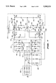
- FIG. 2 is a schematic representation of a preferred embodiment of the present invention as applied to reducing harmonic distortion between a utility system and a DC system;
- FIG. 3 is a plot of currents generated for modulation of the DC system currents and for providing the reinjection of harmonic current in the arrangement shown in FIG. 2;
- FIG. 4 is an enlarged schematic representation of a plot of the simultaneous dc-system regulation and harmonic current generation arrangement achieved with the present invention.
- FIG. 5 is a schematic representation of a control arrangement for controlling switches for DC system current control and harmonic current reinjection into the utility system;
- FIG. 6 is a schematic representation of the system of the present invention used for a DC to AC inverter to provide for transforming energy from renewable energy sources to use in a utility system;
- FIG. 7 is a schematic representation of the present invention used in a bidirectional, that is, DC to AC or AC to DC system;
- FIG. 8 is a schematic representation showing the present invention applied to a 12-pulse topology utility system
- FIG. 9 is a schematic representation of a control arrangement for controlling the switches in a system where an inverter is used
- FIG. 10 is a schematic representation of a control arrangement of the invention used with a current source DC system
- FIG. 11 is a representation of a variation of an impedance network comprising a high pass filter used for injecting a harmonic current into the utility system;
- FIG. 12 illustrates the impedance network of FIG. 11 comprising pure capacitance impedance.
- FIG. 1 illustrates a simplified three-phase alternating current to direct current power conversion system 10.
- System 10 converts power from a three-phase source 12, which comprises three single-phase voltage sources 14A, 14B and 14C connected in a standard wye or star configuration. Each phase includes internal inductance 16A, 16B and 16C. Direct current power is provided at terminals 18A and 18B.
- Power conversion system 10 includes a conventional three-phase, six-pulse full-bridge diode rectifier 20.
- a large filter capacitor 22 is connected across terminals 18A and 18B to provide a substantially ripple free, unregulated but constant DC output voltage.
- the DC voltage appearing across terminals 18A and 18B is unregulated in that the voltage magnitude is dependent upon the line to line voltages from three-phase source 12.
- rectification as illustrated in FIG. 1, draws non-sinusoidal line currents from three-phase source 12 and harmonic current distortions occur.
- each of the harmonic components of the input line currents can be calculated. Table 1 below provides a partial tabulation of the 5th, 7th, 11th and 13th magnitude values as a fraction of the base fundamental frequency.
- TDD Total Harmonic Distortion
- a harmonic reducing system or circuit 30 is shown as part of an AC to DC power conversion system 32.
- a utility system grid has been simplified and modeled as an equivalent three-phase source 34.
- Three-phase source 34 is modeled as three single-phase ideal AC voltage sources 36A, 36B and 36C connected conventionally in a wye or star arrangement with a common or neutral point 38.
- each voltage source 36A, 36B and 36C is connected to an inductor 38A, 38B and 38C which are used to model the utility system equivalent impedance, plus any inductance inserted intentionally to reduce harmonic distortion at the source.
- the equivalent utility system impedance resistance has been neglected.
- Inductors 38A, 38B and 38C are connected with lines 40A, 40B and 40C to a conventional three-phase, six-pulse, full-bridge diode rectifier 42. Rectified unregulated output voltages from rectifier 42 are provided on lines 44A and 44B.
- harmonic current reducing system or circuit 30 is connected to rectifier 42 at output lines 44A and 44B.
- Harmonic current reducing system 30 includes a current generator or modulator denoted generally at 46 (which provides a regulated DC output voltage) and a harmonic injection current feedback path 48.
- harmonic current reducing system 30 provides a substantially constant regulated DC output voltage across output terminals 50A and 50B.
- Lines 52A and 52B connect a DC system denoted generally at 54 to power conversion system 32.
- DC system 54 typically is part of switch-mode power supplies, uninterruptable power supplies, adjustable speed drives, battery chargers or the like, or maybe part of an industrial process that include induction heating, arc welding or electroplating.
- Modulator 46 includes two step-up or "boost" converters 56 and 58. As shown, step-up converters 56 and 58 are connected in series through a junction point 60 across terminals 50A and 50B. A controller 62 provides control signals along signal lines 64 and 66 to operate controllable high frequency switches 68 and 70, respectively, of step-up converters 56 and 58, respectively. Two small capacitors 57 and 59 are included to provide a path for high-switching frequency current ripples. Alternatively, these can be placed across the branches of an impedance network shown at 71.
- High frequency switches 68 and 70 may be any of a number of well known switches, such as Insulated Gate Bipolar Transistors (IGBTs) or Gate Turn off Thyristors (GTOs).
- GTO's which are used in the preferred embodiment work similar to normal thyristors, except GTO's have the capability of being turned off by applying a large negative current flow to the gate.
- diodes may be placed across any of the switches in any of the embodiments in a direction antiparallel to the switches. This protects from reverse voltages damaging the switches. Placing diodes in this way for protection purposes is common to people skilled in the art.
- Impedance network 71 comprises three substantially identical impedance branches 72A, 72B and 72C, each of which is connected to a corresponding line 40A, 40B and 40C of the three-phase system.
- the impedance branches 72A, 72B, 72C each include series connected inductors 73A, 73B and 73C and capacitors 75A, 75B and 75C.
- the branches can be made into high pass filters for each phase of the AC system as well by connecting resistances in parallel with the inductors. These filters are tuned near a selected frequency related to the fundamental frequency.
- the impedances of branches 72A, 72B and 72C should be as near identical as possible.
- the impedance branches of network 71 can be designed to provide reactive power (vars) at line frequency to supply the reactive power requirements of the system which results in a leading power factor, which is desirable.
- Controller 62 uses known techniques for controlling switches 68 and 70 of step-up converters 56 and 58, respectively, at a desired frequency to provide a desired DC current, I d , to DC system 54 and a third harmonic frequency injection current, i 3 , that is proportional to the load current I d .
- Each of the third harmonic frequency injection currents i 3 in lines 44A and 44B is generated by step-up converters 56 and 58 and combined at junction point 60 to form a third harmonic frequency injection current 2i 3 , that is provided to impedance network 71 along feedback current path 48.
- controller 62 operates step-up converter 56 to draw from rectifier 42 a current, i x equal to the load current and the third harmonic current as represented by the following equation.
- controller 62 operates step-up converter 58 to provide a current, i y , to rectifier 42 through line 44B.
- the provided current i y is equal to the load current and the third harmonic current as given by the following equation.
- FIG. 3 shows currents i x and i y .
- Controller 62 is made of known components, and is made to operate the switches in response to a comparison between what is desired as a reference current, based on reference voltage V d , and what is actually the measured current on the respective lines 44A and 44B.
- a reference current I d ,Ref is generated on a line 80. This I d ,Ref is obtained by comparing a reference voltage with a measured voltage using a proportional integral PI regulator 82. The reference voltage is selected to be higher than the peak line to line voltage.
- the reference voltage is provided on line 84 and is compared with the measured voltage V d , which is between the terminals 50A and 50B.
- the amplitude I 3 of the third harmonic frequency injection current i 3 is proportional to the reference current, and thus, the reference current I d ,Ref is passed through an amplifier 88 that provides a current along a line 90 to a multiplier 92.
- Injection of a third harmonic current into the utility system which harmonic current is obtained by modulating the rectified output currents, reduces the magnitude of harmonics in the line currents.
- the magnitude or amplitude of the injected current is proportional to the load current I d provided to DC system 54.
- a proportional multiplying factor, k is chosen to minimize a particular harmonic or combination thereof. For example, by means of Fourier analysis, it can be shown that if the fifth harmonic current is reduced to zero where the system inductance is assumed to be negligible (inductors 38A, 38B and 38C equal to zero), the multiplying factor k is equal to 0.64 times the reference current.
- the multiplying factor k is equal to 0.682 times the reference current.
- Other multiplying factors may be calculated as desired to minimize other harmonic currents or combinations thereof.
- the value of multiplying factor k provided by amplifier 88 may be adjusted to account for finite system inductance, if desired, and to further minimize remaining harmonic currents.
- a conventional phase-locked loop comprising a phase detector 94, a low pass filter 98, a voltage controlled oscillator 100 and a divider 102 is provided.
- the phase detector 94 is provided with an input line 95 that detects the zero cross of the respective phases on lines 40A, 40B and 40C as represented by line to line voltage, V LL .
- Phase detector 94 basically multiplies this line voltage signal with a square wave signal of the same frequency, providing an output signal which is passed through a low pass filter 98 to a voltage control oscillator 100, which, in turn, generates a square-wave signal equal to three times the frequency of the fundamental.
- This third harmonic frequency signal is passed through a divider 102 to reduce it to the fundamental frequency.
- the voltage controlled oscillator 100 can be selected to produce any desired harmonic frequency. Of course, divider 102 would be correspondingly adjusted to reduce the harmonic frequency to the fundamental frequency for comparison by phase detector 94.
- the output of the voltage controlled oscillator 100 is then passed through an active filter 104 which will permit a sine wave third harmonic signal to pass.
- the active filter 104 will take out all frequencies other than the third harmonic, or, in other words, a 180 Hz signal will be passed out along the line 106 to the multiplier 92.
- the amplitude of this third harmonic signal on line 106 is provided so that the desired amplitude from amplifier 88 is maintained to correspond to the amplitude of the signal on line 90. This will provide an output signal of i 3 along the lines 108 equal to the desired amplitude of the modulated reference current at the desired harmonic frequency.
- the line to line voltage, V LL is delayed by an angle ⁇ .
- Integrated circuits used for thyristor control can also provide the signal which represents V LL , but delayed by angle ⁇ .
- the switches 68 and 70 are providing currents that are present on line 48 comprising the reference DC current plus the harmonic injection current, minus the reference current minus the harmonic injection current, respectively, the i 3 current on line 108 is precisely synchronized and in phase with the fundamental frequency. This current i 3 is added to the reference current I d at summing junction 109, and it is subtracted from the reference current I d in summing junction 110.
- the control signal for controlling switch 68 is generated from a current mode controller 112 which has its inputs connected to the output of the summing junction 109 (I d +i 3 ) and to a measured current on line 44A which may be sensed with a current sensor 113 shown in FIG. 2.
- a second current mode controller 114 has as one input the reference signal I d -i 3 , which is the output of summing junction 110, and as a second input, a measured current on line 44B using a current sensor schematically shown at 115 in FIG. 2.
- the function of the current mode controllers 112 and 114 controlling the switches 68 and 70 is to provide i x and i y , respectively, equal to the respective reference current input.
- Various forms of current mode controllers are well known. The simplest is a tolerance band controller as shown and described on page 147 of Power Electronics by Ned Mohan et al, John Wiley & Sons (1989). Also, such controllers are described at page 323 of IEEE Transactions on Industrial Electronics, Volume 37, Number 4, (March 1990).
- Commercially available integrated circuits also have the ability to control switches 68 and 70 to modulate the DC current and provide the third harmonic current. The current mode controllers thus modulate the current signals to provide a 2i 3 current on line 48.
- FIG. 4 illustrates the DC current I d represented by a line 116 and superimposed thereon is the third harmonic current represented by line 119 with the tolerance band indicated by dotted lines 118 and 120.
- the controllers provide the desired total current level of I d +i 3 or, I d -i 3 , depending on the switch being controlled.
- FIG. 4 The representation in FIG. 4 is for explanation purposes only.
- the injection current of the present invention can be used for providing a desired harmonic current to allow a nearly sinusoidal current interface between a three-phase utility and a renewable energy source, such as a wind generator, or solar cells, fuel cells or a small hydroplant.
- a renewable energy source such as a wind generator, or solar cells, fuel cells or a small hydroplant.
- a renewable energy source providing a voltage V d is connected into lines 120 and 122, which are coupled across two step-down or "Buck" converters indicated generally at 121 and 129.
- Converters 121 and 129 include capacitors 123 and 124 connected to a center tap 125, which connects to a junction 126 between diodes 127 and 128 of converters 121 and 129, respectively.
- Ripple current control capacitors 131 and 131A are connected between junction 126 and lines 133A and 135A which lead from inductors 133 and 135 to a power inverter 136.
- first and second switches 130 and 132 are in lines 120 and 122, respectively, between the junctions with the respective capacitors 123 and 124 and the diodes 127 and 128.
- the switches can be placed in other arrangements to form the step-down converters.
- the capacitors 123 and 124 form storage capacitors for storing energy, and hence voltages on lines 120 and 122.
- Current from the renewable energy source is conducted through the inductors 133 and 135, to power inverter 136.
- the inverter 136 comprises a thyristor inverter of known design which is provided with signals to control gates that permit the DC system current to be pulsed into separate phase lines 138, 140 and 142 that lead to an AC generating system indicated schematically and generally at 144.
- the inverter 136 can be made up of GTOs.
- GTOs require current commutation capacitors to be added for satisfactory operation as is known and described in FIG. 7 of a paper entitled "Description and Perspective Application of New Multi-Terminal HVDC System Concepts", by L. Knudsen, B. Hansson and A. Ekstrom, published by Cigre, 112 boulevard Haussman, 75008 Paris, as Number 14-201 and presented Aug. 26-Sep. 1, 1990.
- a switch control circuit indicated at 146 in FIG. 6 is used for controlling the switches 130 and 132 at the selected frequency.
- FIG. 9 illustrates schematically the control circuit 146 for the inverter arrangement. As shown, control circuit 146 is substantially similar to the control circuit of FIGS. 2 and 5 with differences residing in the generation of the reference current on line 80. Referring to FIG. 9, the reference current is generated based on the DC voltage V d across lines 120 and 122 and the time varying voltage v INV provided across inverter 136. The DC voltage V d is provided to a maximum power calculator 137 of conventional design on a line 139.
- Maximum power calculator 137 provides an output signal on line 141 that is proportional to the maximum power that can be obtained from the renewable energy source connected across lines 120 and 122, such as a solar cell power system.
- Line 141 is connected to a divider circuit 143 that receives the average voltage across the inverter 136 as a second input on a line 145.
- the average voltage on line 145 is obtained by supplying the time varying voltage v INV on line 147 to a low pass filter 149.
- the divider 143 then divides the maximum power signal on line 141 by the average voltage signal from low pass filter 149 on line 145 to obtain the reference current on line 80.
- the reference current is combined with a selected harmonic injection current signal in the same manner as described with control circuit 62 to provide control signals to switches 130 and 132.
- the other components shown in FIG. 9 are numbered as in FIG. 5.
- V LL on line 195 is passed through a delay circuit illustrated at 153 to delay the firing angle ⁇ of the thyristors.
- the delay circuit 153 can be a TCA 780 circuit made by Siemens.
- the circuit 153 delays V LL by angle ⁇ before providing V LL to phase detector 94.
- the firing angle of the thyristors in inverter 136 can be kept constant.
- Actual and active control of I d in FIG. 6 means one does not have to change the thyristor firing angle in order to regulate power.
- the objective is to provide the correct power to the AC system.
- the present arrangement permits changing the current I d , rather than changing V INV by changing the thyristor firing angle.
- the maximum power calculator 137 may be eliminated, and a suitable signal that represents the controlled desirable power output from the battery storage system provided directly to divider 143.
- the control circuit 146 includes current mode controllers 112 and 114 (FIG. 9) for providing a signal to each of the separate switches 130 and 132.
- Current mode controllers 112 and 114 compare the generated reference current, I d -i 3 and I d +i 3 , with the measured current in the respective inductors 133 and 135 connected to the inverter 136.
- the currents are added at junction 126 so that 2i 3 is on a line 148 which is used for injecting current into the individual AC lines 138, 140 and 142 for reducing a desired harmonic.
- the harmonic current is synchronized and in phase and delayed by angle ⁇ through delay circuit 153.
- the impedance network for each of the AC lines 138, 140 and 142 is indicated at 150, in general, and each branch includes an inductor and capacitor in series connected to the separate line.
- the pure capacitance impedance or the high pass filter arrangement previously described can also be used for the injection of current into the lines of the AC system.
- the 2i 3 current on line 148 is thus divided so that two-thirds of i 3 is provided to each AC phase.
- the injection of the harmonic current through impedance network 150 provides the harmonic current needed to substantially reduce the total harmonic distortion at the alternating current generating system.
- FIG. 7 the present invention is shown for applications such as battery storage where bidirectional power flow is required.
- a utility system grid modeled as a three-phase source indicated at 160, which has inductors in lines 162, 164 and 166.
- a bidirectional converter indicated at 170 is connected to each of the lines, and is made up of thyristors shown generally at 172 and 174.
- thyristors 172A, 172B and 172C and 174A, 174B and 174C are gated properly they provide for conversion of the AC input to a rectified signal on output lines 176 and 178.
- Each of the lines in the converter has thyristors in parallel with the rectifying thyristors and active in opposite directions, so when the parallel thyristors are operated to conduct in opposite direction, a DC current on the lines 176 and 178 will be pulsed, upon proper gating of the parallel thyristors, to provide for pulsed currents into each of the three-phase lines 162, 164 and 166.
- the converter 170 is a well known arrangement using line commutated thyristors, or gate-turnoff thyristors (GTO's) with capacitor commutating, or similar components.
- GTO's gate-turnoff thyristors
- the thyristors indicated at 172A, 172B and 172C, and as at 174A, 174B and 174C, can have a continuous gate pulse when they are operating in the rectifying mode, that is converting the AC signals into DC signals.
- These components must not be diodes, but they can be GTO'S.
- These same thyristors 172A, 172B and 172C and 174A, 174B and 174C will have no gate pulses and will not conduct during the time when the parallel thyristors are operating in an inverter mode, and thus when stored or generated energy at a DC voltage is changed into an AC voltage that is provided back to the utility system.
- the lines 176 and 178 have inductors 180 and 182 therein which are commonly used in step-up or step-down converters.
- Line 176 has a diode 184 permitting DC currents to go to an output terminal 186 and connected in parallel with the diode 184 is a switch 188.
- line 178 has a diode 188 therein leading from a terminal 190 of the DC system, and a voltage V d is present across the terminals 186 and 190.
- a switch 192 is also connected in parallel with the diode 188.
- a pair of capacitors 194 and 196 are connected across the terminals 186 and 190, and a center tap line 198 between the capacitors 194 and 196 leads to a junction 200, to which a current feedback line 202 is connected.
- Junction 200 is connected across a switch 204 and an antiparallel diode 206 to a node 176A and is also connected through a switch 208 and an antiparallel connected diode 210 to a node 178A.
- Ripple current control capacitors 197 and 198 are connected from junction 200 to the respective lines 176 and 178.
- the switch control circuit indicated at 214 is made so that it controls the switches 204 and 208 to provide current pulses at the desired frequency when the unit is operating as an AC generating-DC load system, in the same manner as shown in FIG. 2.
- a switching frequency would be provided as previously explained and the current i 3 in FIG. 2 is added in line 176 to the DC current I d , and is subtracted in line 178 from the current I d , with the current direction as indicated by arrows 205.
- the current will be 2i 3 , which is carried on line 202 to the three branch impedance network 218.
- the branches are series connected inductors and capacitors, with each being connected to a separate one of the three-phase lines 162, 164 and 166.
- switches 204 and 208 are operated and switches 188 and 192 remain open.
- switches 188 and 192 operate and switches 204 and 208 are open.
- the energy could be stored on the DC system in a battery during AC to DC operation.
- the switches 204 and 208 would be disabled, and the control 214 would then, in response to signals, provide 2i 3 on line 202 by operating the switches 188 and 192.
- Current i 3 is subtracted in line 176 to the DC current I d and is added to I d in line 178.
- Current direction in this mode is indicated by arrows 207.
- FIG. 7 is essentially a combination of operations of FIGS. 2 and 6.
- circuit topologies discussed in the previous figures are all of a six-pulse nature, where if the harmonic problem was not corrected, current harmonics on the order of 6n ⁇ 1 (that is, 5, 7, 11, 13, 17, 19 etc.) would be generated.
- the devices of the present invention for injecting currents back into the generating system can be extended into 12-pulse topologies in higher power applications.
- a 30° phase shift is achieved by delta-wye and delta-delta transformer connections, and the current harmonics are reduced to the order of 12n ⁇ 1 (that is, 11, 13, 23, 25, etc.).
- the dominant 5th and 7th current harmonics of the 6-pulse converter are inherently eliminated.
- a 12-pulse system is shown in FIG. 8.
- An AC generating system 220 provides three-phase power at lines 222, 224, and 226 is connected to a delta to wye transformer indicated generally at 230, and which also includes a delta-delta transformer section 232, to provide a 30° phase shift, to one output side.
- the output or secondary wye connection side of the transformer indicated at 234 is passed through a converter of conventional design indicated at 236 to provide a DC output along the line 238 which is provided through a boost converter assembly 240 and is carried through to a DC system 242 on the line 239.
- the delta connected secondary of the transformer 232 section is indicated at 242, and is connected to a diode converter 244 which is connected to a DC line 248 from a second boost converter assembly 249 that is connected to the DC system through line 246.
- the injected current is equal to the ninth harmonic, i 9 , of the fundamental system frequency.
- the magnitude or amplitude of the injected current is again proportional to the load current provided to the DC system 243.
- the magnitude of the ninth harmonic injected current is equal to 0.33 times the load current 0.33I d ) supplied to DC system 243.
- other harmonic current combinations may be minimized to provide other injected current magnitude values.
- the magnitude of the ninth harmonic injected current i 9 may be adjusted to further minimize remaining harmonic currents, thus further reducing the total harmonic distortion.
- the boost converter assemblies 240 and 249 each comprise two of the boost converters such as those shown in FIG. 2 at 56 and 58. These numerals are used for indicating that each part of the assembly has a switching connection such as those shown at 68 and 70.
- An output line 252 from the boost converter assembly 240 carries a current that is equal to 2i 9 , current where the injected current is to be equal to the ninth harmonic current. Line 252 is connected to the center tap 254 of the wye secondary 234 of the transformer.
- the boost assembly 249 includes step-up or boost converters 58 and 56, as shown, which provides another 2i 9' current along the line 256 to an impedance network 260 that injects a third of the 2i 9' current into each of the individual lines coming from the delta connected secondary 242, to inject current that is equal to 2 ⁇ 0.33 I d , the current flowing in lines 238.
- the switch controllers providing the modulated DC current to provide the 2i 9' current are controlled to account for and correlate to the 30° phase shift provided in the transformer.
- a tap is made for each of the converters from at least one of the individual output lines from the output sides of the transformer secondaries 234 and 242 to provide a phase signal so that the current generated is precisely synchronized in phase.
- FIG. 8 illustrates the applicability of the invention to 12 pulse topologies, and permits injection of the current directly into the AC side of the system. 12 pulse topologies may also be used for DC to AC power flow and for bidirectional power flow.
- the input AC current is highly distorted, and the displacement power factor also becomes very poor.
- Attempts to correct the poor displacement power factor have been made by using a diode rectifier for obtaining the DC voltage, and then using a DC-DC step-down converter.
- Such circuits are well known, since they have the same interface as the voltage source DC system shown in FIG. 2, for example, (the diode rectifier 42 in FIG. 2) the present current modulation arrangement disclosed previously can be applied to that type of circuit without any problem. It is also possible using the proposed approach to control the output DC current directly, and, as shown in FIG. 10, the type of converter, which is known in the art and is disclosed, for example, in U.S. Pat. No.
- the converter is indicated at 42, inasmuch as it is of substantially the same design as the converter shown in FIG. 2, and is connected to a DC system 270.
- the lines 272 and 274 coming from the DC system to the converter 42 include inductors 276 and 278, respectively, which are parts of the step-up converters 280 and 282, respectively.
- the step-up converters in this instance have capacitors at 284 and 285 in the lines 272 and 274.
- the capacitor 284 is used to transfer energy from an inductor 276 to an inductor 286, and on the opposite line, capacitor 285 transfers energy between inductor 278 and inductor 288.
- the step-up converters 280 and 282 include diodes 290 and 292 and switches 294 and 296, respectively, that are connected from the respective lines 272 and 274 to a common center line 298.
- the switches 294 and 296 are controlled by a controller 299.
- the controller inputs are derived in a manner similar to that shown in FIG. 5, and a PI regulator 301 receives I ORef and I O measured, and provides an output current I dRef . This is used as shown for the reference current in FIG. 5, to develop a reference current for a multiplier 92, which also receives a phase signal along a line 303.
- the reference current is provided to multiplier 92 through a multiplier amplifier 88.
- a circuit indicated at 305 is essentially a pair of summing junctions that sum the reference current along the line 307 with an i 3 current signal along the line 309 to provide two outputs, one I d +i 3 , and one I d -i 3 to the controller 299.
- the controller 299 is provided the reference currents, and also receives the measured currents, and controls the switches 294 and 296 in the manner previously explained to maintain the desired current in the system.
- the current flowing in the inductors 276 and 278 will be I d +i 3 and I d -i 3 , as shown.
- a current 2i 3 will be injected through the line 298 utilizing the impedance network shown in FIG. 2 comprising three branches, each of which has a series connected inductor and capacitance tuned to a desired frequency.
- Small capacitors 300 and 302 are connected across the line 298 and lines 272 and 274, respectively to allow flow of ripple current. This system will produce modulating currents for reducing the harmonic distortion, as previously explained.
- Drawbacks of a current source system namely, input current distortion and poor displacement power factor are taken care of, and I O is controllable.
- the circuit of FIG. 10 can be adapted for bidirectional power flow, if diodes 290 and 292 were replaced by controllable switches and the rectifier circuit 42 was replaced with a suitable voltage converter as shown at 170 in FIG. 7. Such arrangement is shown on page 345, FIG. 30 of "Advances in Switched Mode Power conversion", Teslaco Power Electronics Series, Volume 2, by Cuk and Middlebrook (1981).
- the input reference and measured signals used to provide a switch control signal can be either a DC voltage or a DC current, for controlling the modulating converters which provide the harmonic current signal precisely in phase with the AC side, and which is injected back into the AC system through the impedance network.
- the reinjection of the harmonic currents, whether it is the third or ninth harmonic as disclosed, using series inductance and capacitance branches provides for a low loss, inexpensive injection of the desired harmonic current for protecting the AC system from harmonic currents.
- the arrangement shown results in a slightly leading power factor at the line frequency, which is desirable in order to cancel a lagging power factor currents drawn by many loads. Additionally, a regulated DC output voltage or desired power flow is achieved with the present arrangement.
- the series inductance-capacitance branches of the impedance network be sharply tuned for the respective third or ninth harmonic frequency.
- the series inductance-capacitance branches should be tuned at a frequency different from, but close to, the desired frequency of the injected harmonic. As a consequence, sinking of the harmonic currents from the AC system is avoided, which is usually a drawback for passive filters, and a slight unbalance in the three branches of the impedance network does not lead to a large percentage unbalance in the individual inductance-capacitance branch impedances at the third harmonic frequency.
- the impedance network 71H comprises a high pass filter for each branch 72H, 72I and 72J by connecting a resistor 77H, 77I and 77J, respectively in parallel with inductors 73H, 73I and 73J, respectively.
- Capacitors 75H, 75I and 75J are connected as shown.
- the impedance network is further modified to use pure capacitance.
- the network 71K comprises capacitors 75K, 75L and 75M connected to lines 48 and lines 40A, 40B and 40C.
- the system of the present invention also permits applying some of the known or older injection techniques, such as the use of active filters, to be applied in addition to the present invention circuitry, where applications requiring a very low total harmonic distortion is essential.
- high frequency isolation transformers can be applied to the systems, to provide electrical isolation. This would be to provide electrical isolation between the DC lines or bus and the utility voltages.
- the high frequency transformer can be located as part of the boost converters 56 and 58.
- Such a current source converter is shown on page 226 of the book "Power Electronics", by Ned Mohan et al., John Wiley & Sons (1989). Additionally, this particular textbook at page 147 and following explains how the tolerance band control for current regulated modulation is carried out, and principles shown can be applied to the present generation of i 3 and i 9 currents.
- the present invention must provide sinusoidal currents in a three-phase utility interface.
- the most common application is in the form of the invention as shown in FIG. 2 where a three-phase utility voltage is rectified into a DC voltage using diode-bridge rectifiers.
- the arrangement is useful for DC to AC inversion, where power flows from the DC side of the converter into a utility, and in battery storage circuits where power flow must be bidirectional.
- Regulated DC bus voltage is obtained with the present system, and because there is no need for having large inductors in order to obtain a pure DC current, costs are reduced, while the advantage of a regulated DC voltage is obtained.
- the device is low cost, with high energy efficiency and low power losses. Operation causes very low electromagnetic interference, and the switching frequency does not have to be excessively high.
Abstract
Description
              TABLE 1
______________________________________
Line-Current Distortion
Harmonic      Fraction of
Number        Fundamental
______________________________________
1             1.00
5             0.67
7             0.44
11            0.09
13            0.06
:             :
______________________________________
i.sub.x =(I.sub.d =l.sub.3)
i.sub.y =(I.sub.d -i.sub.3)
Claims (24)
Priority Applications (5)
| Application Number | Priority Date | Filing Date | Title |
|---|---|---|---|
| US07/807,717 US5345375A (en) | 1991-12-16 | 1991-12-16 | System and method for reducing harmonic currents by current injection |
| JP5511117A JPH07502160A (en) | 1991-12-16 | 1992-12-14 | 3-phase power supply voltage conversion |
| EP93901345A EP0617858A4 (en) | 1991-12-16 | 1992-12-14 | Conversion of three-phase line voltages. |
| PCT/US1992/010780 WO1993012576A1 (en) | 1991-12-16 | 1992-12-14 | Conversion of three-phase line voltages |
| US08/194,701 US5499178A (en) | 1991-12-16 | 1994-02-10 | System for reducing harmonics by harmonic current injection |
Applications Claiming Priority (1)
| Application Number | Priority Date | Filing Date | Title |
|---|---|---|---|
| US07/807,717 US5345375A (en) | 1991-12-16 | 1991-12-16 | System and method for reducing harmonic currents by current injection |
Related Child Applications (1)
| Application Number | Title | Priority Date | Filing Date |
|---|---|---|---|
| US1768293A Continuation-In-Part | 1991-12-16 | 1993-02-12 |
Publications (1)
| Publication Number | Publication Date |
|---|---|
| US5345375A true US5345375A (en) | 1994-09-06 |
Family
ID=25197035
Family Applications (1)
| Application Number | Title | Priority Date | Filing Date |
|---|---|---|---|
| US07/807,717 Expired - Lifetime US5345375A (en) | 1991-12-16 | 1991-12-16 | System and method for reducing harmonic currents by current injection |
Country Status (4)
| Country | Link |
|---|---|
| US (1) | US5345375A (en) |
| EP (1) | EP0617858A4 (en) |
| JP (1) | JPH07502160A (en) |
| WO (1) | WO1993012576A1 (en) |
Cited By (169)
| Publication number | Priority date | Publication date | Assignee | Title |
|---|---|---|---|---|
| US5432695A (en) * | 1993-09-17 | 1995-07-11 | The Center For Innovative Technology | Zero-voltage-switched, three-phase PWM rectifier inverter circuit |
| US5459392A (en) * | 1993-12-27 | 1995-10-17 | Megapower Corp. | Unity power factor power supply which includes an electromagnetic interference reduction circuit |
| WO1995034119A1 (en) * | 1994-06-06 | 1995-12-14 | Helionetics, Inc. | Structure and method for performing active injection mode filtering on an ac power system |
| US5499178A (en) * | 1991-12-16 | 1996-03-12 | Regents Of The University Of Minnesota | System for reducing harmonics by harmonic current injection |
| US5532575A (en) * | 1994-01-08 | 1996-07-02 | Gec Alsthom Limited | Multilevel converter with capacitor voltage balancing |
| US5568371A (en) * | 1994-09-29 | 1996-10-22 | Texas A&M University System | Active harmonic power filter apparatus and method |
| US5574635A (en) * | 1993-11-24 | 1996-11-12 | Schneider Electric Sa | AC-DC converter comprising a filtering device |
| EP0780758A2 (en) | 1995-12-18 | 1997-06-25 | Symbios Logic Inc. | Data processing and storage method and apparatus |
| US5656924A (en) * | 1995-09-27 | 1997-08-12 | Schott Power Systems Inc. | System and method for providing harmonic currents to a harmonic generating load connected to a power system |
| US5751150A (en) * | 1995-08-11 | 1998-05-12 | Aerovironment | Bidirectional load and source cycler |
| US5757637A (en) * | 1993-05-11 | 1998-05-26 | Switchtec Power Systems Limited | Power converter with star configured modules |
| US5786990A (en) * | 1996-09-27 | 1998-07-28 | National Semiconductor Corporation | Implementation of ripple steering to converter topologies |
| DE19736786A1 (en) * | 1997-08-23 | 1999-02-25 | Asea Brown Boveri | U-converter |
| US5886891A (en) * | 1998-07-17 | 1999-03-23 | Lucent Technologies Inc. | Three-phase boost converter having wye-connected input capacitors and method of operation thereof |
| US5903066A (en) * | 1996-10-29 | 1999-05-11 | Texas A & M University System | Active interphase reactor for 12-pulse rectifier |
| US5936855A (en) * | 1996-09-03 | 1999-08-10 | Mercury Electric Corporation | Harmonic correction of 3-phase rectifiers and converters |
| US5963441A (en) * | 1998-09-03 | 1999-10-05 | Eaton Corporation | Alternating current rectifier bridge and system for measuring average current per bridge segment |
| US5999419A (en) * | 1998-08-07 | 1999-12-07 | National Semiconductor Corporation | Non-isolated boost converter with current steering |
| US6008999A (en) * | 1998-08-07 | 1999-12-28 | National Semiconductor Corporation | Non-isolated buck converter with input current steering |
| US6014017A (en) * | 1996-10-15 | 2000-01-11 | Siemens Aktiengesellschaft | Method and apparatus for power factor correction by a compensation device having a pulse converter |
| US6075350A (en) * | 1998-04-24 | 2000-06-13 | Lockheed Martin Energy Research Corporation | Power line conditioner using cascade multilevel inverters for voltage regulation, reactive power correction, and harmonic filtering |
| US6084791A (en) * | 1997-01-31 | 2000-07-04 | Siemens Aktiengesellschaft | Control system for supply recovery of energy from a three-phase network into a converter with a variable voltage link |
| US6166931A (en) * | 1998-11-27 | 2000-12-26 | Dornier Gmbh | Filter for a D. C. converter |
| US6208537B1 (en) * | 1999-09-28 | 2001-03-27 | Rockwell Technologies, Llc | Series resonant sinewave output filter and design methodology |
| USRE37126E1 (en) | 1995-09-14 | 2001-04-03 | Lockheed Martin Energy Systems, Inc. | Multilevel cascade voltage source inverter with seperate DC sources |
| US20010038000A1 (en) * | 1994-11-18 | 2001-11-08 | Thommes James M. | Method and apparatus for receiving a universal input voltage in a welding power source |
| US6395027B1 (en) | 2000-04-25 | 2002-05-28 | The Penn State Research Foundation | Artificial heart with arrhythmia signalling |
| WO2002049185A1 (en) * | 2000-12-14 | 2002-06-20 | Northeastern University | A robust controller for controlling a ups in unbalanced operation |
| US6451055B1 (en) | 2000-04-25 | 2002-09-17 | The Penn State Research Foundation | Artificial heart data communication system |
| US6459597B1 (en) * | 2000-12-19 | 2002-10-01 | Fuji Electric Co., Ltd. | Electric power conversion apparatus with noise reduction device |
| US6458164B1 (en) | 2000-04-25 | 2002-10-01 | The Penn State Research Foundation | Artificial heart with energy recovery |
| US6472775B1 (en) | 2001-11-30 | 2002-10-29 | Ballard Power Systems Corporation | Method and system for eliminating certain harmonics in a distributed power system |
| US6478820B1 (en) | 2000-04-25 | 2002-11-12 | The Penn State Research Foundation | Artificial heart with synchronous rectification |
| US20030062774A1 (en) * | 2000-12-14 | 2003-04-03 | Gerardo Escobar | Robust controller for controlling a ups in unbalanced operation |
| US6577487B2 (en) * | 1996-05-29 | 2003-06-10 | Asea Brown Boveri Ab | Reduction of harmonics in AC machines |
| US6579315B1 (en) | 2000-04-25 | 2003-06-17 | The Penn State Research Foundation | Artificial heart power supply system |
| US6603290B2 (en) * | 2001-11-26 | 2003-08-05 | Visteon Global Technologies, Inc. | Anti-islanding detection scheme for distributed power generation |
| KR20030095130A (en) * | 2002-06-11 | 2003-12-18 | 김규식 | A New Harmonic Reduction Method of Diode Rectifier by Zero-Sequence Current Injection |
| US20040024668A1 (en) * | 2001-05-09 | 2004-02-05 | Manabu Sakamoto | Image providing device |
| US6704214B1 (en) * | 2003-02-19 | 2004-03-09 | Eaton Corporation | Excitation control system and method employing de-excitation trip logic |
| US20050013147A1 (en) * | 2003-06-04 | 2005-01-20 | Universidad De Santiago De Chile | Method and apparatus to reduce distortion of currents feeding an AC/DC rectifier system |
| US20050275368A1 (en) * | 2003-01-20 | 2005-12-15 | Mika Sippola | Filter network |
| US20060164875A1 (en) * | 2005-01-27 | 2006-07-27 | Silvio Colombi | AC/DC converter and method of modulation thereof |
| US20060215430A1 (en) * | 2005-03-25 | 2006-09-28 | Tyco Electronics Power Systems, Inc. | Modulation controller, method of controlling and three phase converter system employing the same |
| US20070290670A1 (en) * | 2004-08-25 | 2007-12-20 | Lee Sung H | Device for Reducing Harmonics in Three-Phase Poly-Wire Power Lines |
| US7362162B2 (en) | 2000-07-13 | 2008-04-22 | Epcos Ag | Line filter |
| US20080150366A1 (en) * | 2006-12-06 | 2008-06-26 | Solaredge, Ltd. | Method for distributed power harvesting using dc power sources |
| US20080309158A1 (en) * | 2005-12-22 | 2008-12-18 | Siemens Aktiengesellschaft | Transmission System for Interchanging Information Data Between an Electrical Load and an Upstream Converter |
| US20090039852A1 (en) * | 2007-08-06 | 2009-02-12 | Solaredge Technologies Ltd. | Digital average input current control in power converter |
| US20090145480A1 (en) * | 2007-12-05 | 2009-06-11 | Meir Adest | Photovoltaic system power tracking method |
| US20090146667A1 (en) * | 2007-12-05 | 2009-06-11 | Meir Adest | Testing of a photovoltaic panel |
| US20090206666A1 (en) * | 2007-12-04 | 2009-08-20 | Guy Sella | Distributed power harvesting systems using dc power sources |
| US20090243398A1 (en) * | 2008-03-28 | 2009-10-01 | Yohanan Tom G | Systems and Methods for Reducing Distortion in a Power Source Using an Active Harmonics Filter |
| US20100020577A1 (en) * | 2006-12-08 | 2010-01-28 | Siemens Aktiengesellschaft | Production of a real power equilibrium of the phase modules of a converter |
| FR2936112A1 (en) * | 2008-09-12 | 2010-03-19 | Mge Ups Systems | Converter device for uninterrupted power supply, has step-up chopper circuits respectively connected to branches and providing output voltages, and inductive unit i.e. inductor, placed between network input and input point of branches |
| US20100072819A1 (en) * | 2008-09-22 | 2010-03-25 | Ablerex Electronics Co., Ltd | Bi-directional DC to DC power converter having a neutral terminal |
| US20100301991A1 (en) * | 2009-05-26 | 2010-12-02 | Guy Sella | Theft detection and prevention in a power generation system |
| US20110026281A1 (en) * | 2009-07-31 | 2011-02-03 | Chapman Patrick L | Apparatus and method for controlling dc-ac power conversion |
| US20110084553A1 (en) * | 2007-12-04 | 2011-04-14 | Meir Adest | Distributed power system using direct current power sources |
| US20110121652A1 (en) * | 2006-12-06 | 2011-05-26 | Guy Sella | Pairing of components in a direct current distributed power generation system |
| US20110125431A1 (en) * | 2007-12-05 | 2011-05-26 | Meir Adest | Testing of a Photovoltaic Panel |
| US20110133552A1 (en) * | 2009-12-01 | 2011-06-09 | Yaron Binder | Dual Use Photovoltaic System |
| US20110181340A1 (en) * | 2010-01-27 | 2011-07-28 | Meir Gazit | Fast Voltage Level Shifter Circuit |
| WO2011051096A3 (en) * | 2009-10-30 | 2011-09-15 | Siemens Aktiengesellschaft | An ac-dc converter and an inverter |
| US20120249045A1 (en) * | 2011-04-01 | 2012-10-04 | Lsis Co., Ltd. | Medium voltage inverter system |
| US8289742B2 (en) | 2007-12-05 | 2012-10-16 | Solaredge Ltd. | Parallel connected inverters |
| US20120262957A1 (en) * | 2010-10-14 | 2012-10-18 | Fuji Electric Co., Ltd. | Distributed power supply system |
| US8319471B2 (en) | 2006-12-06 | 2012-11-27 | Solaredge, Ltd. | Battery power delivery module |
| US8384243B2 (en) | 2007-12-04 | 2013-02-26 | Solaredge Technologies Ltd. | Distributed power harvesting systems using DC power sources |
| US20130070499A1 (en) * | 2011-09-21 | 2013-03-21 | Zahra Mohajerani | Switched Power Converter |
| US20130112674A1 (en) * | 2010-05-28 | 2013-05-09 | Esab Ab | Short arc welding system |
| US20130119038A1 (en) * | 2010-05-28 | 2013-05-16 | Esab Ab | Short arc welding system |
| US20130128629A1 (en) * | 2010-04-15 | 2013-05-23 | Alstom Technology Ltd | Hybrid 2-level and multilevel hvdc converter |
| US20130128636A1 (en) * | 2010-07-30 | 2013-05-23 | Alstom Technology Ltd | HVDC Converter Comprising Fullbridge Cells For Handling A DC Side Short Circuit |
| US20130134786A1 (en) * | 2010-09-22 | 2013-05-30 | Toyota Jidosha Kabushiki Kaisha | Dc-dc converter comprising dc power sources to be connected in parallel or in series |
| US8473250B2 (en) | 2006-12-06 | 2013-06-25 | Solaredge, Ltd. | Monitoring of distributed power harvesting systems using DC power sources |
| CN103270679A (en) * | 2010-12-20 | 2013-08-28 | 施耐德东芝换流器欧洲公司 | Ac/dc power converter with improved power factor and improved thdi |
| US8531055B2 (en) * | 2006-12-06 | 2013-09-10 | Solaredge Ltd. | Safety mechanisms, wake up and shutdown methods in distributed power installations |
| US20130279211A1 (en) * | 2010-10-27 | 2013-10-24 | Alstom Technology Ltd | Modular Multilevel Converter |
| US8570005B2 (en) | 2011-09-12 | 2013-10-29 | Solaredge Technologies Ltd. | Direct current link circuit |
| US20140009982A1 (en) * | 2012-07-05 | 2014-01-09 | Delta Electronics, Inc. | Feedback control circuit for power converter and power converter system |
| US20140146583A1 (en) * | 2010-08-24 | 2014-05-29 | Alstom Technology Ltd | Hvdc converter with neutral-point connected zero-sequence dump resistor |
| US8773878B2 (en) * | 2012-05-24 | 2014-07-08 | Rong Shin Jong Co., Ltd. | Three-phase reactor power saving device |
| US8779711B2 (en) | 2011-04-20 | 2014-07-15 | Princeton Power Systems, Inc. | Induction motor driver |
| US8816535B2 (en) | 2007-10-10 | 2014-08-26 | Solaredge Technologies, Ltd. | System and method for protection during inverter shutdown in distributed power installations |
| US8861234B2 (en) | 2009-06-15 | 2014-10-14 | Alstom Technology Ltd | Voltage source converter having chain link converter for use in high voltage DC transmission |
| US8861231B2 (en) | 2010-02-09 | 2014-10-14 | Alstom Technology Ltd | Converter |
| US8929094B2 (en) | 2009-10-12 | 2015-01-06 | Solarbridge Technologies, Inc. | Power inverter docking system for photovoltaic modules |
| US8934268B2 (en) * | 2010-04-08 | 2015-01-13 | Alstom Technology Ltd | Power electronic converter for use in high voltage direct current power transmission |
| US8957645B2 (en) | 2008-03-24 | 2015-02-17 | Solaredge Technologies Ltd. | Zero voltage switching |
| US8988838B2 (en) | 2012-01-30 | 2015-03-24 | Solaredge Technologies Ltd. | Photovoltaic panel circuitry |
| US9000617B2 (en) | 2008-05-05 | 2015-04-07 | Solaredge Technologies, Ltd. | Direct current power combiner |
| US9006569B2 (en) | 2009-05-22 | 2015-04-14 | Solaredge Technologies Ltd. | Electrically isolated heat dissipating junction box |
| US20150103570A1 (en) * | 2012-03-22 | 2015-04-16 | Sew-Eurodrive Gmbh & Co. Kg | Circuit Configuration and System of Capacitors |
| US9065299B2 (en) | 2010-06-18 | 2015-06-23 | Alstom Technology Ltd | Converter for HVDC transmission and reactive power compensation |
| US9088178B2 (en) | 2006-12-06 | 2015-07-21 | Solaredge Technologies Ltd | Distributed power harvesting systems using DC power sources |
| US20150244259A1 (en) * | 2014-02-21 | 2015-08-27 | Airbus Operations Gmbh | Bipolar high-voltage network and method for operating a bipolar high-voltage network |
| US9130401B2 (en) | 2006-12-06 | 2015-09-08 | Solaredge Technologies Ltd. | Distributed power harvesting systems using DC power sources |
| US9130458B2 (en) | 2010-03-15 | 2015-09-08 | Alstom Technology Ltd. | Static VAR compensator with multilevel converter |
| US9197068B2 (en) | 2010-09-30 | 2015-11-24 | Abb Research Ltd. | Coordinated control of multi-terminal HVDC systems |
| US20150349821A1 (en) * | 2014-05-29 | 2015-12-03 | Qualcomm Incorporated | Feedback receive path with rf filter |
| US9209693B2 (en) | 2011-11-07 | 2015-12-08 | Alstom Technology Ltd | Control circuit for DC network to maintain zero net change in energy level |
| US9235228B2 (en) | 2012-03-05 | 2016-01-12 | Solaredge Technologies Ltd. | Direct current link circuit |
| US9263183B2 (en) | 2011-04-27 | 2016-02-16 | Sunpower Corporation | Modular photovoltaic power supply assembly |
| US9318974B2 (en) | 2014-03-26 | 2016-04-19 | Solaredge Technologies Ltd. | Multi-level inverter with flying capacitor topology |
| US9350269B2 (en) | 2009-07-31 | 2016-05-24 | Alstom Technology Ltd. | Configurable hybrid converter circuit |
| US9350250B2 (en) | 2011-06-08 | 2016-05-24 | Alstom Technology Ltd. | High voltage DC/DC converter with cascaded resonant tanks |
| US9362848B2 (en) | 2011-11-17 | 2016-06-07 | Alstom Technology Ltd. | Hybrid AC/DC converter for HVDC applications |
| US9401599B2 (en) | 2010-12-09 | 2016-07-26 | Solaredge Technologies Ltd. | Disconnection of a string carrying direct current power |
| US20160233757A1 (en) * | 2013-12-11 | 2016-08-11 | Solaronics S.A. | Low level harmonics control system for groups of impedances connected in parallel in a three-phase system |
| US20160241127A1 (en) * | 2013-10-07 | 2016-08-18 | General Electric Technology Gmbh | Voltage source converter |
| US9444320B1 (en) | 2012-04-16 | 2016-09-13 | Performance Controls, Inc. | Power controller having active voltage balancing of a power supply |
| US9479061B2 (en) | 2011-08-01 | 2016-10-25 | Alstom Technology Ltd. | DC to DC converter assembly |
| US9548619B2 (en) | 2013-03-14 | 2017-01-17 | Solaredge Technologies Ltd. | Method and apparatus for storing and depleting energy |
| US9584044B2 (en) | 2013-03-15 | 2017-02-28 | Sunpower Corporation | Technologies for converter topologies |
| WO2017074777A1 (en) * | 2015-10-30 | 2017-05-04 | Associated Universities, Inc. | Optimal response reflectionless filters |
| US9647442B2 (en) | 2010-11-09 | 2017-05-09 | Solaredge Technologies Ltd. | Arc detection and prevention in a power generation system |
| US9647544B2 (en) | 2012-03-19 | 2017-05-09 | Kabushiki Kaisha Toyota Chuo Kenkyusho | Magnetic component, power converter and power supply system |
| WO2017102296A1 (en) * | 2015-12-14 | 2017-06-22 | Robert Bosch Gmbh | Voltage converter, electric drive system and method for reducing interference voltages |
| US20170229972A1 (en) * | 2014-08-13 | 2017-08-10 | Inesc Tec - Instituto de Engenharia de Sistema e Computadores, Tecnologia e Ciência | Ac/dc converter with three to single phase matrix converter, full-bridge ac/dc converter and hf transformer |
| US9812984B2 (en) | 2012-01-30 | 2017-11-07 | Solaredge Technologies Ltd. | Maximizing power in a photovoltaic distributed power system |
| US9819178B2 (en) | 2013-03-15 | 2017-11-14 | Solaredge Technologies Ltd. | Bypass mechanism |
| US9831824B2 (en) | 2007-12-05 | 2017-11-28 | SolareEdge Technologies Ltd. | Current sensing on a MOSFET |
| US9853565B2 (en) | 2012-01-30 | 2017-12-26 | Solaredge Technologies Ltd. | Maximized power in a photovoltaic distributed power system |
| US9855376B2 (en) | 2014-07-25 | 2018-01-02 | Minnetronix, Inc. | Power scaling |
| US9866098B2 (en) | 2011-01-12 | 2018-01-09 | Solaredge Technologies Ltd. | Serially connected inverters |
| US9870016B2 (en) | 2012-05-25 | 2018-01-16 | Solaredge Technologies Ltd. | Circuit for interconnected direct current power sources |
| US9929636B2 (en) | 2014-02-19 | 2018-03-27 | Mitsubishi Electric Corporation | DC power-supply device, motor drive device including the same, and refrigeration-cycle application device including the motor drive device |
| US9941813B2 (en) | 2013-03-14 | 2018-04-10 | Solaredge Technologies Ltd. | High frequency multi-level inverter |
| US9954358B2 (en) | 2012-03-01 | 2018-04-24 | General Electric Technology Gmbh | Control circuit |
| US10061957B2 (en) | 2016-03-03 | 2018-08-28 | Solaredge Technologies Ltd. | Methods for mapping power generation installations |
| US10115841B2 (en) | 2012-06-04 | 2018-10-30 | Solaredge Technologies Ltd. | Integrated photovoltaic panel circuitry |
| US10149933B2 (en) | 2014-07-25 | 2018-12-11 | Minnetronix, Inc. | Coil parameters and control |
| US10170911B1 (en) * | 2016-08-25 | 2019-01-01 | Veritone Alpha, Inc. | Providing phase synchronization and harmonic harvesting |
| US10193395B2 (en) | 2015-04-14 | 2019-01-29 | Minnetronix, Inc. | Repeater resonator |
| US20190067943A1 (en) * | 2016-05-06 | 2019-02-28 | Wobben Properties Gmbh | Method for compensating feed-in currents in a wind park |
| US10230310B2 (en) | 2016-04-05 | 2019-03-12 | Solaredge Technologies Ltd | Safety switch for photovoltaic systems |
| US10342908B2 (en) | 2015-01-14 | 2019-07-09 | Minnetronix, Inc. | Distributed transformer |
| US20190238046A1 (en) * | 2016-09-30 | 2019-08-01 | Daikin Industries, Ltd. | Active filter device, air conditioning device, and air conditioning system |
| US10374577B2 (en) | 2015-10-30 | 2019-08-06 | Associated Universities, Inc. | Optimal response reflectionless filters |
| US10406267B2 (en) | 2015-01-16 | 2019-09-10 | Minnetronix, Inc. | Data communication in a transcutaneous energy transfer system |
| US10483902B1 (en) * | 2018-08-29 | 2019-11-19 | Rockwell Automation Technologies, Inc. | System and method for reducing current harmonic distortion in a motor controller |
| US10498217B1 (en) | 2018-07-02 | 2019-12-03 | Palo Alto Research Center Incorporated | Coordinated power converters for increased efficiency and power electronics lifetime |
| US10530321B2 (en) | 2015-10-30 | 2020-01-07 | Associated Universities, Inc. | Deep rejection reflectionless filters |
| US10574136B2 (en) * | 2018-04-17 | 2020-02-25 | Abb Schweiz Ag | Methods and systems for controlling current source rectifiers |
| US10599113B2 (en) | 2016-03-03 | 2020-03-24 | Solaredge Technologies Ltd. | Apparatus and method for determining an order of power devices in power generation systems |
| US10673229B2 (en) | 2010-11-09 | 2020-06-02 | Solaredge Technologies Ltd. | Arc detection and prevention in a power generation system |
| US10673222B2 (en) | 2010-11-09 | 2020-06-02 | Solaredge Technologies Ltd. | Arc detection and prevention in a power generation system |
| US10734912B2 (en) * | 2016-08-24 | 2020-08-04 | Beckhoff Automation Gmbh | Stator device for a linear motor, linear drive system, and method for operating a stator device |
| US10931119B2 (en) | 2012-01-11 | 2021-02-23 | Solaredge Technologies Ltd. | Photovoltaic module |
| US10945753B2 (en) | 2015-07-15 | 2021-03-16 | Stryker Corporation | System and method for controlling an ultrasonic tool |
| US11018623B2 (en) | 2016-04-05 | 2021-05-25 | Solaredge Technologies Ltd. | Safety switch for photovoltaic systems |
| US11081608B2 (en) | 2016-03-03 | 2021-08-03 | Solaredge Technologies Ltd. | Apparatus and method for determining an order of power devices in power generation systems |
| US11177663B2 (en) | 2016-04-05 | 2021-11-16 | Solaredge Technologies Ltd. | Chain of power devices |
| US11264947B2 (en) | 2007-12-05 | 2022-03-01 | Solaredge Technologies Ltd. | Testing of a photovoltaic panel |
| US11296650B2 (en) | 2006-12-06 | 2022-04-05 | Solaredge Technologies Ltd. | System and method for protection during inverter shutdown in distributed power installations |
| US11309832B2 (en) | 2006-12-06 | 2022-04-19 | Solaredge Technologies Ltd. | Distributed power harvesting systems using DC power sources |
| US11309816B2 (en) | 2017-05-05 | 2022-04-19 | Wobben Properties Gmbh | Wind turbine with overload-capable converter system |
| US11342749B1 (en) * | 2019-11-22 | 2022-05-24 | Smart Wires Inc. | Integration of a power flow control unit |
| US11387769B2 (en) * | 2016-12-14 | 2022-07-12 | Nanjing Chervon Industry Co., Ltd. | Power tool |
| US20220302868A1 (en) * | 2016-12-14 | 2022-09-22 | Nanjing Chervon Industry Co., Ltd. | Power tool |
| US11569659B2 (en) | 2006-12-06 | 2023-01-31 | Solaredge Technologies Ltd. | Distributed power harvesting systems using DC power sources |
| US11687112B2 (en) | 2006-12-06 | 2023-06-27 | Solaredge Technologies Ltd. | Distributed power harvesting systems using DC power sources |
| US11728768B2 (en) | 2006-12-06 | 2023-08-15 | Solaredge Technologies Ltd. | Pairing of components in a direct current distributed power generation system |
| US11735910B2 (en) | 2006-12-06 | 2023-08-22 | Solaredge Technologies Ltd. | Distributed power system using direct current power sources |
| WO2023213447A1 (en) * | 2022-05-04 | 2023-11-09 | Siemens Energy Global GmbH & Co. KG | Electrolysis plant and plant network comprising an electrolysis plant and a renewable energy plant |
| US11855231B2 (en) | 2006-12-06 | 2023-12-26 | Solaredge Technologies Ltd. | Distributed power harvesting systems using DC power sources |
| US11881814B2 (en) | 2005-12-05 | 2024-01-23 | Solaredge Technologies Ltd. | Testing of a photovoltaic panel |
| US11888387B2 (en) | 2006-12-06 | 2024-01-30 | Solaredge Technologies Ltd. | Safety mechanisms, wake up and shutdown methods in distributed power installations |
Families Citing this family (5)
| Publication number | Priority date | Publication date | Assignee | Title |
|---|---|---|---|---|
| DE4430394A1 (en) * | 1994-08-26 | 1995-01-26 | Manfred Prof Dr Ing Gekeler | Three-phase rectifier circuit having virtually sinusoidal input currents and a regulated DC output voltage |
| JPH08196077A (en) * | 1994-11-18 | 1996-07-30 | Toshiba Corp | Power converter and air-conditioner employing it |
| US7619906B2 (en) * | 2005-03-01 | 2009-11-17 | York International Corporation | System for precharging a DC link in a variable speed drive |
| CN104065259B (en) * | 2013-03-18 | 2016-08-03 | 台达电子工业股份有限公司 | Filter, power converter and CM Noise Cancellation |
| DE102020116889A1 (en) | 2020-06-26 | 2021-12-30 | ACD Antriebstechnik GmbH | Three-phase boost converter with PFC |
Citations (6)
| Publication number | Priority date | Publication date | Assignee | Title |
|---|---|---|---|---|
| GB1252572A (en) * | 1968-05-06 | 1971-11-10 | ||
| US4053820A (en) * | 1976-01-29 | 1977-10-11 | Wisconsin Alumni Research Foundation | Active filter |
| US4184197A (en) * | 1977-09-28 | 1980-01-15 | California Institute Of Technology | DC-to-DC switching converter |
| US4224660A (en) * | 1979-01-22 | 1980-09-23 | The Regents Of The University Of Minnesota | Composite filter for suppressing harmonic frequencies on electric power transmission lines |
| US4730243A (en) * | 1985-12-23 | 1988-03-08 | Sundstrand Corporation | EMI reduction circuit |
| JPH0386022A (en) * | 1989-08-30 | 1991-04-11 | Fuji Electric Co Ltd | Higher harmonic compensator |
-
1991
- 1991-12-16 US US07/807,717 patent/US5345375A/en not_active Expired - Lifetime
-
1992
- 1992-12-14 EP EP93901345A patent/EP0617858A4/en not_active Withdrawn
- 1992-12-14 WO PCT/US1992/010780 patent/WO1993012576A1/en not_active Application Discontinuation
- 1992-12-14 JP JP5511117A patent/JPH07502160A/en active Pending
Patent Citations (6)
| Publication number | Priority date | Publication date | Assignee | Title |
|---|---|---|---|---|
| GB1252572A (en) * | 1968-05-06 | 1971-11-10 | ||
| US4053820A (en) * | 1976-01-29 | 1977-10-11 | Wisconsin Alumni Research Foundation | Active filter |
| US4184197A (en) * | 1977-09-28 | 1980-01-15 | California Institute Of Technology | DC-to-DC switching converter |
| US4224660A (en) * | 1979-01-22 | 1980-09-23 | The Regents Of The University Of Minnesota | Composite filter for suppressing harmonic frequencies on electric power transmission lines |
| US4730243A (en) * | 1985-12-23 | 1988-03-08 | Sundstrand Corporation | EMI reduction circuit |
| JPH0386022A (en) * | 1989-08-30 | 1991-04-11 | Fuji Electric Co Ltd | Higher harmonic compensator |
Non-Patent Citations (9)
| Title |
|---|
| "Advances in Switched-Mode Power Conversion", Teslaco Power Electronics Series, Vol. II, by Cuk and Middlebrook, (1981). * |
| "Description and Prospective Applcations of New Multi-Terminal HVDC System Concepts", by L. Knudsen et al., published by Cigre, 112 Boulevard Haussmann, 75008 Paris, No. 14-201, presented 26 August - 1 September 1990. * |
| "Generalised Method of Harmonic Reduction in A.C.-D.C. Convertors by Harmonic Current Injection", by A. Ametani, published in PROC. IEE., Vol. 119, No. 7, July 1972, pages 857-864. * |
| "Harmonic Reduction in D.C. - Ripple Reinjection", by J. F. Baird et al., published in IEE PROC., Vol. 127, Pt. C. No. 5, September 1980, pages 294-303. * |
| "Harmonic Reduction in Multiplex Convertors by Triple-Frequency Current Injection ", by B. M. Bird et al., published in PROC. IEE., Vol. 116, No. 10, October 1969, pages 1730-1734. * |
| "Harmonic Reduction in Thyristor Converts by Harmonic Current Injection", by A. Ametani, published in IEEE Transactions on Power Apparatus and Systems, Vol. PAS-95, No. 2, March/April 1976, pages 441-449. * |
| "Increasing the Pulse Number of AC-DC Convertors by Current Reinjection Techniques", by J. Arrillaga et al., published in IEEE Transactions on Power Apparatus and Systems, Vol. PAS-102, No. 8, August 1983, pages 2649-2655. * |
| Selected pages from IEEE Transactions on Industrial Electronics, Vol. 37, No. 4, (August 1990). * |
| Selected pages from Power Electronics by Ned Mohan et al., published by John Wiley & Sons, (1989). * |
Cited By (351)
| Publication number | Priority date | Publication date | Assignee | Title |
|---|---|---|---|---|
| US5499178A (en) * | 1991-12-16 | 1996-03-12 | Regents Of The University Of Minnesota | System for reducing harmonics by harmonic current injection |
| US5757637A (en) * | 1993-05-11 | 1998-05-26 | Switchtec Power Systems Limited | Power converter with star configured modules |
| US5432695A (en) * | 1993-09-17 | 1995-07-11 | The Center For Innovative Technology | Zero-voltage-switched, three-phase PWM rectifier inverter circuit |
| US5574635A (en) * | 1993-11-24 | 1996-11-12 | Schneider Electric Sa | AC-DC converter comprising a filtering device |
| US5459392A (en) * | 1993-12-27 | 1995-10-17 | Megapower Corp. | Unity power factor power supply which includes an electromagnetic interference reduction circuit |
| US5532575A (en) * | 1994-01-08 | 1996-07-02 | Gec Alsthom Limited | Multilevel converter with capacitor voltage balancing |
| US5608276A (en) * | 1994-06-06 | 1997-03-04 | Helionetics, Inc. | Structure and method for performing active injection mode filtering on an AC power system |
| US5614770A (en) * | 1994-06-06 | 1997-03-25 | Helionetics, Inc. | Structure and method for performing active injection mode filtering on an AC power system |
| WO1995034119A1 (en) * | 1994-06-06 | 1995-12-14 | Helionetics, Inc. | Structure and method for performing active injection mode filtering on an ac power system |
| US5568371A (en) * | 1994-09-29 | 1996-10-22 | Texas A&M University System | Active harmonic power filter apparatus and method |
| US20010038000A1 (en) * | 1994-11-18 | 2001-11-08 | Thommes James M. | Method and apparatus for receiving a universal input voltage in a welding power source |
| US7319206B2 (en) | 1994-11-18 | 2008-01-15 | Illinois Tool Works Inc. | Method and apparatus for receiving a universal input voltage in a welding power source |
| US20040195225A1 (en) * | 1994-11-18 | 2004-10-07 | Illinois Tool Works, Inc. | Method and apparatus for receiving a universal input voltage in a welding power source |
| US20070295703A1 (en) * | 1994-11-18 | 2007-12-27 | Illinois Tool Works Inc. | Method And Apparatus For Receiving A Universal Input Voltage In A Welding Power Source |
| EP0843822A2 (en) * | 1995-08-11 | 1998-05-27 | Aerovironment inc. | A bidirectional load and source cycler |
| US5751150A (en) * | 1995-08-11 | 1998-05-12 | Aerovironment | Bidirectional load and source cycler |
| EP0843822B1 (en) * | 1995-08-11 | 2005-11-30 | Aerovironment inc. | A bidirectional load and source cycler |
| USRE37126E1 (en) | 1995-09-14 | 2001-04-03 | Lockheed Martin Energy Systems, Inc. | Multilevel cascade voltage source inverter with seperate DC sources |
| US5656924A (en) * | 1995-09-27 | 1997-08-12 | Schott Power Systems Inc. | System and method for providing harmonic currents to a harmonic generating load connected to a power system |
| EP0780758A2 (en) | 1995-12-18 | 1997-06-25 | Symbios Logic Inc. | Data processing and storage method and apparatus |
| US6577487B2 (en) * | 1996-05-29 | 2003-06-10 | Asea Brown Boveri Ab | Reduction of harmonics in AC machines |
| US5936855A (en) * | 1996-09-03 | 1999-08-10 | Mercury Electric Corporation | Harmonic correction of 3-phase rectifiers and converters |
| US5786990A (en) * | 1996-09-27 | 1998-07-28 | National Semiconductor Corporation | Implementation of ripple steering to converter topologies |
| US6014017A (en) * | 1996-10-15 | 2000-01-11 | Siemens Aktiengesellschaft | Method and apparatus for power factor correction by a compensation device having a pulse converter |
| US5903066A (en) * | 1996-10-29 | 1999-05-11 | Texas A & M University System | Active interphase reactor for 12-pulse rectifier |
| US6084791A (en) * | 1997-01-31 | 2000-07-04 | Siemens Aktiengesellschaft | Control system for supply recovery of energy from a three-phase network into a converter with a variable voltage link |
| DE19736786A1 (en) * | 1997-08-23 | 1999-02-25 | Asea Brown Boveri | U-converter |
| US6075350A (en) * | 1998-04-24 | 2000-06-13 | Lockheed Martin Energy Research Corporation | Power line conditioner using cascade multilevel inverters for voltage regulation, reactive power correction, and harmonic filtering |
| US5886891A (en) * | 1998-07-17 | 1999-03-23 | Lucent Technologies Inc. | Three-phase boost converter having wye-connected input capacitors and method of operation thereof |
| US6008999A (en) * | 1998-08-07 | 1999-12-28 | National Semiconductor Corporation | Non-isolated buck converter with input current steering |
| US5999419A (en) * | 1998-08-07 | 1999-12-07 | National Semiconductor Corporation | Non-isolated boost converter with current steering |
| US5963441A (en) * | 1998-09-03 | 1999-10-05 | Eaton Corporation | Alternating current rectifier bridge and system for measuring average current per bridge segment |
| US6166931A (en) * | 1998-11-27 | 2000-12-26 | Dornier Gmbh | Filter for a D. C. converter |
| US6208537B1 (en) * | 1999-09-28 | 2001-03-27 | Rockwell Technologies, Llc | Series resonant sinewave output filter and design methodology |
| US6451055B1 (en) | 2000-04-25 | 2002-09-17 | The Penn State Research Foundation | Artificial heart data communication system |
| US6395027B1 (en) | 2000-04-25 | 2002-05-28 | The Penn State Research Foundation | Artificial heart with arrhythmia signalling |
| US6579315B1 (en) | 2000-04-25 | 2003-06-17 | The Penn State Research Foundation | Artificial heart power supply system |
| US6478820B1 (en) | 2000-04-25 | 2002-11-12 | The Penn State Research Foundation | Artificial heart with synchronous rectification |
| US6458164B1 (en) | 2000-04-25 | 2002-10-01 | The Penn State Research Foundation | Artificial heart with energy recovery |
| US7362162B2 (en) | 2000-07-13 | 2008-04-22 | Epcos Ag | Line filter |
| US6940187B2 (en) | 2000-12-14 | 2005-09-06 | Northeastern University | Robust controller for controlling a UPS in unbalanced operation |
| US20030062774A1 (en) * | 2000-12-14 | 2003-04-03 | Gerardo Escobar | Robust controller for controlling a ups in unbalanced operation |
| WO2002049185A1 (en) * | 2000-12-14 | 2002-06-20 | Northeastern University | A robust controller for controlling a ups in unbalanced operation |
| US6459597B1 (en) * | 2000-12-19 | 2002-10-01 | Fuji Electric Co., Ltd. | Electric power conversion apparatus with noise reduction device |
| US20040024668A1 (en) * | 2001-05-09 | 2004-02-05 | Manabu Sakamoto | Image providing device |
| US6603290B2 (en) * | 2001-11-26 | 2003-08-05 | Visteon Global Technologies, Inc. | Anti-islanding detection scheme for distributed power generation |
| US6472775B1 (en) | 2001-11-30 | 2002-10-29 | Ballard Power Systems Corporation | Method and system for eliminating certain harmonics in a distributed power system |
| KR20030095130A (en) * | 2002-06-11 | 2003-12-18 | 김규식 | A New Harmonic Reduction Method of Diode Rectifier by Zero-Sequence Current Injection |
| US20050275368A1 (en) * | 2003-01-20 | 2005-12-15 | Mika Sippola | Filter network |
| US7116076B2 (en) * | 2003-01-20 | 2006-10-03 | Schaffner Emv Ag | Filter network for motor control systems |
| US6704214B1 (en) * | 2003-02-19 | 2004-03-09 | Eaton Corporation | Excitation control system and method employing de-excitation trip logic |
| US20050013147A1 (en) * | 2003-06-04 | 2005-01-20 | Universidad De Santiago De Chile | Method and apparatus to reduce distortion of currents feeding an AC/DC rectifier system |
| US7551461B2 (en) * | 2003-06-04 | 2009-06-23 | Miguel Villablanca | Method and apparatus to reduce distortion of currents feeding an AC/DC rectifier system |
| US7629786B2 (en) * | 2004-08-25 | 2009-12-08 | Sung Ho Lee | Device for reducing harmonics in three-phase poly-wire power lines |
| US20070290670A1 (en) * | 2004-08-25 | 2007-12-20 | Lee Sung H | Device for Reducing Harmonics in Three-Phase Poly-Wire Power Lines |
| US7474081B2 (en) * | 2005-01-27 | 2009-01-06 | General Electric Company | AC/DC converter and method of modulation thereof |
| US20060164875A1 (en) * | 2005-01-27 | 2006-07-27 | Silvio Colombi | AC/DC converter and method of modulation thereof |
| US20060215430A1 (en) * | 2005-03-25 | 2006-09-28 | Tyco Electronics Power Systems, Inc. | Modulation controller, method of controlling and three phase converter system employing the same |
| US7492616B2 (en) * | 2005-03-25 | 2009-02-17 | Lineage Power Corporation | Modulation controller, method of controlling and three phase converter system employing the same |
| US11881814B2 (en) | 2005-12-05 | 2024-01-23 | Solaredge Technologies Ltd. | Testing of a photovoltaic panel |
| US20080309158A1 (en) * | 2005-12-22 | 2008-12-18 | Siemens Aktiengesellschaft | Transmission System for Interchanging Information Data Between an Electrical Load and an Upstream Converter |
| US7825533B2 (en) * | 2005-12-22 | 2010-11-02 | Siemens Aktiengesellschaft | Transmission system for interchanging information data between an electrical load and an upstream converter |
| US11961922B2 (en) | 2006-12-06 | 2024-04-16 | Solaredge Technologies Ltd. | Distributed power harvesting systems using DC power sources |
| US11183922B2 (en) | 2006-12-06 | 2021-11-23 | Solaredge Technologies Ltd. | Distributed power harvesting systems using DC power sources |
| US9041339B2 (en) | 2006-12-06 | 2015-05-26 | Solaredge Technologies Ltd. | Battery power delivery module |
| US11962243B2 (en) | 2006-12-06 | 2024-04-16 | Solaredge Technologies Ltd. | Method for distributed power harvesting using DC power sources |
| US9088178B2 (en) | 2006-12-06 | 2015-07-21 | Solaredge Technologies Ltd | Distributed power harvesting systems using DC power sources |
| US11855231B2 (en) | 2006-12-06 | 2023-12-26 | Solaredge Technologies Ltd. | Distributed power harvesting systems using DC power sources |
| US11735910B2 (en) | 2006-12-06 | 2023-08-22 | Solaredge Technologies Ltd. | Distributed power system using direct current power sources |
| US9112379B2 (en) | 2006-12-06 | 2015-08-18 | Solaredge Technologies Ltd. | Pairing of components in a direct current distributed power generation system |
| US11728768B2 (en) | 2006-12-06 | 2023-08-15 | Solaredge Technologies Ltd. | Pairing of components in a direct current distributed power generation system |
| US11687112B2 (en) | 2006-12-06 | 2023-06-27 | Solaredge Technologies Ltd. | Distributed power harvesting systems using DC power sources |
| US11682918B2 (en) | 2006-12-06 | 2023-06-20 | Solaredge Technologies Ltd. | Battery power delivery module |
| US11658482B2 (en) | 2006-12-06 | 2023-05-23 | Solaredge Technologies Ltd. | Distributed power harvesting systems using DC power sources |
| US20110121652A1 (en) * | 2006-12-06 | 2011-05-26 | Guy Sella | Pairing of components in a direct current distributed power generation system |
| US11598652B2 (en) | 2006-12-06 | 2023-03-07 | Solaredge Technologies Ltd. | Monitoring of distributed power harvesting systems using DC power sources |
| US11594880B2 (en) | 2006-12-06 | 2023-02-28 | Solaredge Technologies Ltd. | Distributed power harvesting systems using DC power sources |
| US11594881B2 (en) | 2006-12-06 | 2023-02-28 | Solaredge Technologies Ltd. | Distributed power harvesting systems using DC power sources |
| US8013472B2 (en) | 2006-12-06 | 2011-09-06 | Solaredge, Ltd. | Method for distributed power harvesting using DC power sources |
| US9130401B2 (en) | 2006-12-06 | 2015-09-08 | Solaredge Technologies Ltd. | Distributed power harvesting systems using DC power sources |
| US11594882B2 (en) | 2006-12-06 | 2023-02-28 | Solaredge Technologies Ltd. | Distributed power harvesting systems using DC power sources |
| US9368964B2 (en) | 2006-12-06 | 2016-06-14 | Solaredge Technologies Ltd. | Distributed power system using direct current power sources |
| US11579235B2 (en) | 2006-12-06 | 2023-02-14 | Solaredge Technologies Ltd. | Safety mechanisms, wake up and shutdown methods in distributed power installations |
| US11575260B2 (en) | 2006-12-06 | 2023-02-07 | Solaredge Technologies Ltd. | Distributed power harvesting systems using DC power sources |
| US11575261B2 (en) | 2006-12-06 | 2023-02-07 | Solaredge Technologies Ltd. | Distributed power harvesting systems using DC power sources |
| US9543889B2 (en) | 2006-12-06 | 2017-01-10 | Solaredge Technologies Ltd. | Distributed power harvesting systems using DC power sources |
| US8319471B2 (en) | 2006-12-06 | 2012-11-27 | Solaredge, Ltd. | Battery power delivery module |
| US11569660B2 (en) | 2006-12-06 | 2023-01-31 | Solaredge Technologies Ltd. | Distributed power harvesting systems using DC power sources |
| US20080150366A1 (en) * | 2006-12-06 | 2008-06-26 | Solaredge, Ltd. | Method for distributed power harvesting using dc power sources |
| US11569659B2 (en) | 2006-12-06 | 2023-01-31 | Solaredge Technologies Ltd. | Distributed power harvesting systems using DC power sources |
| US11476799B2 (en) | 2006-12-06 | 2022-10-18 | Solaredge Technologies Ltd. | Distributed power harvesting systems using DC power sources |
| US11309832B2 (en) | 2006-12-06 | 2022-04-19 | Solaredge Technologies Ltd. | Distributed power harvesting systems using DC power sources |
| US11296650B2 (en) | 2006-12-06 | 2022-04-05 | Solaredge Technologies Ltd. | System and method for protection during inverter shutdown in distributed power installations |
| US11888387B2 (en) | 2006-12-06 | 2024-01-30 | Solaredge Technologies Ltd. | Safety mechanisms, wake up and shutdown methods in distributed power installations |
| US11073543B2 (en) | 2006-12-06 | 2021-07-27 | Solaredge Technologies Ltd. | Monitoring of distributed power harvesting systems using DC power sources |
| US8473250B2 (en) | 2006-12-06 | 2013-06-25 | Solaredge, Ltd. | Monitoring of distributed power harvesting systems using DC power sources |
| US11063440B2 (en) | 2006-12-06 | 2021-07-13 | Solaredge Technologies Ltd. | Method for distributed power harvesting using DC power sources |
| US11043820B2 (en) | 2006-12-06 | 2021-06-22 | Solaredge Technologies Ltd. | Battery power delivery module |
| US8531055B2 (en) * | 2006-12-06 | 2013-09-10 | Solaredge Ltd. | Safety mechanisms, wake up and shutdown methods in distributed power installations |
| US11031861B2 (en) | 2006-12-06 | 2021-06-08 | Solaredge Technologies Ltd. | System and method for protection during inverter shutdown in distributed power installations |
| US11002774B2 (en) | 2006-12-06 | 2021-05-11 | Solaredge Technologies Ltd. | Monitoring of distributed power harvesting systems using DC power sources |
| US10673253B2 (en) | 2006-12-06 | 2020-06-02 | Solaredge Technologies Ltd. | Battery power delivery module |
| US8587151B2 (en) | 2006-12-06 | 2013-11-19 | Solaredge, Ltd. | Method for distributed power harvesting using DC power sources |
| US10637393B2 (en) | 2006-12-06 | 2020-04-28 | Solaredge Technologies Ltd. | Distributed power harvesting systems using DC power sources |
| US9590526B2 (en) | 2006-12-06 | 2017-03-07 | Solaredge Technologies Ltd. | Safety mechanisms, wake up and shutdown methods in distributed power installations |
| US10447150B2 (en) | 2006-12-06 | 2019-10-15 | Solaredge Technologies Ltd. | Distributed power harvesting systems using DC power sources |
| US10230245B2 (en) | 2006-12-06 | 2019-03-12 | Solaredge Technologies Ltd | Battery power delivery module |
| US8659188B2 (en) | 2006-12-06 | 2014-02-25 | Solaredge Technologies Ltd. | Distributed power harvesting systems using DC power sources |
| US9644993B2 (en) | 2006-12-06 | 2017-05-09 | Solaredge Technologies Ltd. | Monitoring of distributed power harvesting systems using DC power sources |
| US10097007B2 (en) | 2006-12-06 | 2018-10-09 | Solaredge Technologies Ltd. | Method for distributed power harvesting using DC power sources |
| US9966766B2 (en) | 2006-12-06 | 2018-05-08 | Solaredge Technologies Ltd. | Battery power delivery module |
| US9960667B2 (en) | 2006-12-06 | 2018-05-01 | Solaredge Technologies Ltd. | System and method for protection during inverter shutdown in distributed power installations |
| US9960731B2 (en) | 2006-12-06 | 2018-05-01 | Solaredge Technologies Ltd. | Pairing of components in a direct current distributed power generation system |
| US9680304B2 (en) | 2006-12-06 | 2017-06-13 | Solaredge Technologies Ltd. | Method for distributed power harvesting using DC power sources |
| US9948233B2 (en) | 2006-12-06 | 2018-04-17 | Solaredge Technologies Ltd. | Distributed power harvesting systems using DC power sources |
| US9853490B2 (en) | 2006-12-06 | 2017-12-26 | Solaredge Technologies Ltd. | Distributed power system using direct current power sources |
| US8144489B2 (en) * | 2006-12-08 | 2012-03-27 | Siemens Aktiengesellschaft | Production of a real power equilibrium of the phase modules of a converter |
| US20100020577A1 (en) * | 2006-12-08 | 2010-01-28 | Siemens Aktiengesellschaft | Production of a real power equilibrium of the phase modules of a converter |
| US8773092B2 (en) | 2007-08-06 | 2014-07-08 | Solaredge Technologies Ltd. | Digital average input current control in power converter |
| US9673711B2 (en) | 2007-08-06 | 2017-06-06 | Solaredge Technologies Ltd. | Digital average input current control in power converter |
| US10116217B2 (en) | 2007-08-06 | 2018-10-30 | Solaredge Technologies Ltd. | Digital average input current control in power converter |
| US10516336B2 (en) | 2007-08-06 | 2019-12-24 | Solaredge Technologies Ltd. | Digital average input current control in power converter |
| US8319483B2 (en) | 2007-08-06 | 2012-11-27 | Solaredge Technologies Ltd. | Digital average input current control in power converter |
| US11594968B2 (en) | 2007-08-06 | 2023-02-28 | Solaredge Technologies Ltd. | Digital average input current control in power converter |
| US20090039852A1 (en) * | 2007-08-06 | 2009-02-12 | Solaredge Technologies Ltd. | Digital average input current control in power converter |
| US8816535B2 (en) | 2007-10-10 | 2014-08-26 | Solaredge Technologies, Ltd. | System and method for protection during inverter shutdown in distributed power installations |
| US8384243B2 (en) | 2007-12-04 | 2013-02-26 | Solaredge Technologies Ltd. | Distributed power harvesting systems using DC power sources |
| US8963369B2 (en) | 2007-12-04 | 2015-02-24 | Solaredge Technologies Ltd. | Distributed power harvesting systems using DC power sources |
| US20090206666A1 (en) * | 2007-12-04 | 2009-08-20 | Guy Sella | Distributed power harvesting systems using dc power sources |
| US20110084553A1 (en) * | 2007-12-04 | 2011-04-14 | Meir Adest | Distributed power system using direct current power sources |
| US8618692B2 (en) | 2007-12-04 | 2013-12-31 | Solaredge Technologies Ltd. | Distributed power system using direct current power sources |
| US9853538B2 (en) | 2007-12-04 | 2017-12-26 | Solaredge Technologies Ltd. | Distributed power harvesting systems using DC power sources |
| US11693080B2 (en) | 2007-12-05 | 2023-07-04 | Solaredge Technologies Ltd. | Parallel connected inverters |
| US20110125431A1 (en) * | 2007-12-05 | 2011-05-26 | Meir Adest | Testing of a Photovoltaic Panel |
| US11183923B2 (en) | 2007-12-05 | 2021-11-23 | Solaredge Technologies Ltd. | Parallel connected inverters |
| US10644589B2 (en) | 2007-12-05 | 2020-05-05 | Solaredge Technologies Ltd. | Parallel connected inverters |
| US20090146667A1 (en) * | 2007-12-05 | 2009-06-11 | Meir Adest | Testing of a photovoltaic panel |
| US10693415B2 (en) | 2007-12-05 | 2020-06-23 | Solaredge Technologies Ltd. | Testing of a photovoltaic panel |
| US20090145480A1 (en) * | 2007-12-05 | 2009-06-11 | Meir Adest | Photovoltaic system power tracking method |
| US11183969B2 (en) | 2007-12-05 | 2021-11-23 | Solaredge Technologies Ltd. | Testing of a photovoltaic panel |
| US11894806B2 (en) | 2007-12-05 | 2024-02-06 | Solaredge Technologies Ltd. | Testing of a photovoltaic panel |
| US9979280B2 (en) | 2007-12-05 | 2018-05-22 | Solaredge Technologies Ltd. | Parallel connected inverters |
| US9407161B2 (en) | 2007-12-05 | 2016-08-02 | Solaredge Technologies Ltd. | Parallel connected inverters |
| US8599588B2 (en) | 2007-12-05 | 2013-12-03 | Solaredge Ltd. | Parallel connected inverters |
| US9831824B2 (en) | 2007-12-05 | 2017-11-28 | SolareEdge Technologies Ltd. | Current sensing on a MOSFET |
| US8289742B2 (en) | 2007-12-05 | 2012-10-16 | Solaredge Ltd. | Parallel connected inverters |
| US8324921B2 (en) | 2007-12-05 | 2012-12-04 | Solaredge Technologies Ltd. | Testing of a photovoltaic panel |
| US9291696B2 (en) | 2007-12-05 | 2016-03-22 | Solaredge Technologies Ltd. | Photovoltaic system power tracking method |
| US11264947B2 (en) | 2007-12-05 | 2022-03-01 | Solaredge Technologies Ltd. | Testing of a photovoltaic panel |
| US9876430B2 (en) | 2008-03-24 | 2018-01-23 | Solaredge Technologies Ltd. | Zero voltage switching |
| US8957645B2 (en) | 2008-03-24 | 2015-02-17 | Solaredge Technologies Ltd. | Zero voltage switching |
| US20090243398A1 (en) * | 2008-03-28 | 2009-10-01 | Yohanan Tom G | Systems and Methods for Reducing Distortion in a Power Source Using an Active Harmonics Filter |
| US7834643B2 (en) | 2008-03-28 | 2010-11-16 | Baker Hughes Incorporated | Systems and methods for reducing distortion in a power source using an active harmonics filter |
| US10468878B2 (en) | 2008-05-05 | 2019-11-05 | Solaredge Technologies Ltd. | Direct current power combiner |
| US9362743B2 (en) | 2008-05-05 | 2016-06-07 | Solaredge Technologies Ltd. | Direct current power combiner |
| US9000617B2 (en) | 2008-05-05 | 2015-04-07 | Solaredge Technologies, Ltd. | Direct current power combiner |
| US11424616B2 (en) | 2008-05-05 | 2022-08-23 | Solaredge Technologies Ltd. | Direct current power combiner |
| FR2936112A1 (en) * | 2008-09-12 | 2010-03-19 | Mge Ups Systems | Converter device for uninterrupted power supply, has step-up chopper circuits respectively connected to branches and providing output voltages, and inductive unit i.e. inductor, placed between network input and input point of branches |
| US20100072819A1 (en) * | 2008-09-22 | 2010-03-25 | Ablerex Electronics Co., Ltd | Bi-directional DC to DC power converter having a neutral terminal |
| US8130524B2 (en) * | 2008-09-22 | 2012-03-06 | Ablerex Electronics Co., Ltd. | Bi-directional DC to DC power converter having a neutral terminal |
| US9537445B2 (en) | 2008-12-04 | 2017-01-03 | Solaredge Technologies Ltd. | Testing of a photovoltaic panel |
| US10461687B2 (en) | 2008-12-04 | 2019-10-29 | Solaredge Technologies Ltd. | Testing of a photovoltaic panel |
| US10686402B2 (en) | 2009-05-22 | 2020-06-16 | Solaredge Technologies Ltd. | Electrically isolated heat dissipating junction box |
| US9748897B2 (en) | 2009-05-22 | 2017-08-29 | Solaredge Technologies Ltd. | Electrically isolated heat dissipating junction box |
| US11509263B2 (en) | 2009-05-22 | 2022-11-22 | Solaredge Technologies Ltd. | Electrically isolated heat dissipating junction box |
| US10411644B2 (en) | 2009-05-22 | 2019-09-10 | Solaredge Technologies, Ltd. | Electrically isolated heat dissipating junction box |
| US9748896B2 (en) | 2009-05-22 | 2017-08-29 | Solaredge Technologies Ltd. | Electrically isolated heat dissipating junction box |
| US11695371B2 (en) | 2009-05-22 | 2023-07-04 | Solaredge Technologies Ltd. | Electrically isolated heat dissipating junction box |
| US9006569B2 (en) | 2009-05-22 | 2015-04-14 | Solaredge Technologies Ltd. | Electrically isolated heat dissipating junction box |
| US10879840B2 (en) | 2009-05-22 | 2020-12-29 | Solaredge Technologies Ltd. | Electrically isolated heat dissipating junction box |
| US10969412B2 (en) | 2009-05-26 | 2021-04-06 | Solaredge Technologies Ltd. | Theft detection and prevention in a power generation system |
| US9869701B2 (en) | 2009-05-26 | 2018-01-16 | Solaredge Technologies Ltd. | Theft detection and prevention in a power generation system |
| US11867729B2 (en) | 2009-05-26 | 2024-01-09 | Solaredge Technologies Ltd. | Theft detection and prevention in a power generation system |
| US8947194B2 (en) | 2009-05-26 | 2015-02-03 | Solaredge Technologies Ltd. | Theft detection and prevention in a power generation system |
| US20100301991A1 (en) * | 2009-05-26 | 2010-12-02 | Guy Sella | Theft detection and prevention in a power generation system |
| US8861234B2 (en) | 2009-06-15 | 2014-10-14 | Alstom Technology Ltd | Voltage source converter having chain link converter for use in high voltage DC transmission |
| US9350269B2 (en) | 2009-07-31 | 2016-05-24 | Alstom Technology Ltd. | Configurable hybrid converter circuit |
| US20110026281A1 (en) * | 2009-07-31 | 2011-02-03 | Chapman Patrick L | Apparatus and method for controlling dc-ac power conversion |
| US9225256B2 (en) * | 2009-07-31 | 2015-12-29 | Sunpower Corporation | Apparatus and method for controlling DC-AC power conversion |
| US20140003100A1 (en) * | 2009-07-31 | 2014-01-02 | Patrick L. Chapman | Apparatus and method for controlling dc-ac power conversion |
| US8482947B2 (en) * | 2009-07-31 | 2013-07-09 | Solarbridge Technologies, Inc. | Apparatus and method for controlling DC-AC power conversion |
| US8929094B2 (en) | 2009-10-12 | 2015-01-06 | Solarbridge Technologies, Inc. | Power inverter docking system for photovoltaic modules |
| WO2011051096A3 (en) * | 2009-10-30 | 2011-09-15 | Siemens Aktiengesellschaft | An ac-dc converter and an inverter |
| US20110133552A1 (en) * | 2009-12-01 | 2011-06-09 | Yaron Binder | Dual Use Photovoltaic System |
| US8710699B2 (en) | 2009-12-01 | 2014-04-29 | Solaredge Technologies Ltd. | Dual use photovoltaic system |
| US10270255B2 (en) | 2009-12-01 | 2019-04-23 | Solaredge Technologies Ltd | Dual use photovoltaic system |
| US11735951B2 (en) | 2009-12-01 | 2023-08-22 | Solaredge Technologies Ltd. | Dual use photovoltaic system |
| US9276410B2 (en) | 2009-12-01 | 2016-03-01 | Solaredge Technologies Ltd. | Dual use photovoltaic system |
| US11056889B2 (en) | 2009-12-01 | 2021-07-06 | Solaredge Technologies Ltd. | Dual use photovoltaic system |
| US9231570B2 (en) | 2010-01-27 | 2016-01-05 | Solaredge Technologies Ltd. | Fast voltage level shifter circuit |
| US8766696B2 (en) | 2010-01-27 | 2014-07-01 | Solaredge Technologies Ltd. | Fast voltage level shifter circuit |
| US9564882B2 (en) | 2010-01-27 | 2017-02-07 | Solaredge Technologies Ltd. | Fast voltage level shifter circuit |
| US20110181340A1 (en) * | 2010-01-27 | 2011-07-28 | Meir Gazit | Fast Voltage Level Shifter Circuit |
| US9917587B2 (en) | 2010-01-27 | 2018-03-13 | Solaredge Technologies Ltd. | Fast voltage level shifter circuit |
| US8861231B2 (en) | 2010-02-09 | 2014-10-14 | Alstom Technology Ltd | Converter |
| US9130458B2 (en) | 2010-03-15 | 2015-09-08 | Alstom Technology Ltd. | Static VAR compensator with multilevel converter |
| US8934268B2 (en) * | 2010-04-08 | 2015-01-13 | Alstom Technology Ltd | Power electronic converter for use in high voltage direct current power transmission |
| US20130128629A1 (en) * | 2010-04-15 | 2013-05-23 | Alstom Technology Ltd | Hybrid 2-level and multilevel hvdc converter |
| US8867242B2 (en) * | 2010-04-15 | 2014-10-21 | Alstom Technology Ltd | Hybrid 2-level and multilevel HVDC converter |
| US10022813B2 (en) * | 2010-05-28 | 2018-07-17 | Esab Ab | Short arc welding system |
| US20190091790A1 (en) * | 2010-05-28 | 2019-03-28 | Esab Ab | Short arc welding system |
| US10195681B2 (en) | 2010-05-28 | 2019-02-05 | Esab Ab | Short arc welding system |
| US20130119038A1 (en) * | 2010-05-28 | 2013-05-16 | Esab Ab | Short arc welding system |
| US10189107B2 (en) * | 2010-05-28 | 2019-01-29 | Esab Ab | Short arc welding system |
| US20130112674A1 (en) * | 2010-05-28 | 2013-05-09 | Esab Ab | Short arc welding system |
| US11638966B2 (en) * | 2010-05-28 | 2023-05-02 | Esab Ab | Short arc welding system |
| US9065299B2 (en) | 2010-06-18 | 2015-06-23 | Alstom Technology Ltd | Converter for HVDC transmission and reactive power compensation |
| US9490693B2 (en) | 2010-06-18 | 2016-11-08 | Alstom Technology Ltd. | Converter for HVDC transmission and reactive power compensation |
| US20130128636A1 (en) * | 2010-07-30 | 2013-05-23 | Alstom Technology Ltd | HVDC Converter Comprising Fullbridge Cells For Handling A DC Side Short Circuit |
| US8867244B2 (en) * | 2010-07-30 | 2014-10-21 | Alstom Technology Ltd. | HVDC converter including fullbridge cells for handling a DC side short circuit |
| US8854843B2 (en) * | 2010-08-24 | 2014-10-07 | Alstom Technology Ltd. | HVDC converter with neutral-point connected zero-sequence dump resistor |
| US20140146583A1 (en) * | 2010-08-24 | 2014-05-29 | Alstom Technology Ltd | Hvdc converter with neutral-point connected zero-sequence dump resistor |
| US20130134786A1 (en) * | 2010-09-22 | 2013-05-30 | Toyota Jidosha Kabushiki Kaisha | Dc-dc converter comprising dc power sources to be connected in parallel or in series |
| US9431824B2 (en) * | 2010-09-22 | 2016-08-30 | Kabushiki Kaisha Toyota Chuo Kenkyusho | DC-DC converter comprising DC power sources to be connected in parallel or in series |
| US9197068B2 (en) | 2010-09-30 | 2015-11-24 | Abb Research Ltd. | Coordinated control of multi-terminal HVDC systems |
| US8743571B2 (en) * | 2010-10-14 | 2014-06-03 | Fuji Electric Co., Ltd. | Distributed power supply system with harmonic signal generation for stabilization |
| US20120262957A1 (en) * | 2010-10-14 | 2012-10-18 | Fuji Electric Co., Ltd. | Distributed power supply system |
| US20130279211A1 (en) * | 2010-10-27 | 2013-10-24 | Alstom Technology Ltd | Modular Multilevel Converter |
| US8848401B2 (en) * | 2010-10-27 | 2014-09-30 | Alstom Technology Ltd. | Modular multilevel power electronic converter having selectively definable circulation path |
| US10931228B2 (en) | 2010-11-09 | 2021-02-23 | Solaredge Technologies Ftd. | Arc detection and prevention in a power generation system |
| US10673229B2 (en) | 2010-11-09 | 2020-06-02 | Solaredge Technologies Ltd. | Arc detection and prevention in a power generation system |
| US11489330B2 (en) | 2010-11-09 | 2022-11-01 | Solaredge Technologies Ltd. | Arc detection and prevention in a power generation system |
| US9647442B2 (en) | 2010-11-09 | 2017-05-09 | Solaredge Technologies Ltd. | Arc detection and prevention in a power generation system |
| US11070051B2 (en) | 2010-11-09 | 2021-07-20 | Solaredge Technologies Ltd. | Arc detection and prevention in a power generation system |
| US10673222B2 (en) | 2010-11-09 | 2020-06-02 | Solaredge Technologies Ltd. | Arc detection and prevention in a power generation system |
| US11349432B2 (en) | 2010-11-09 | 2022-05-31 | Solaredge Technologies Ltd. | Arc detection and prevention in a power generation system |
| US9401599B2 (en) | 2010-12-09 | 2016-07-26 | Solaredge Technologies Ltd. | Disconnection of a string carrying direct current power |
| US9935458B2 (en) | 2010-12-09 | 2018-04-03 | Solaredge Technologies Ltd. | Disconnection of a string carrying direct current power |
| US11271394B2 (en) | 2010-12-09 | 2022-03-08 | Solaredge Technologies Ltd. | Disconnection of a string carrying direct current power |
| US9036370B2 (en) * | 2010-12-20 | 2015-05-19 | Schneider Toshiba Inverter Europe Sas | AC/DC power converter with improved power factor and improved THDi |
| CN103270679A (en) * | 2010-12-20 | 2013-08-28 | 施耐德东芝换流器欧洲公司 | Ac/dc power converter with improved power factor and improved thdi |
| US20130286689A1 (en) * | 2010-12-20 | 2013-10-31 | Schneider Toshiba Inverter Europe Sas | Ac/dc power converter with improved power factor and improved thdi |
| US9866098B2 (en) | 2011-01-12 | 2018-01-09 | Solaredge Technologies Ltd. | Serially connected inverters |
| US10666125B2 (en) | 2011-01-12 | 2020-05-26 | Solaredge Technologies Ltd. | Serially connected inverters |
| US11205946B2 (en) | 2011-01-12 | 2021-12-21 | Solaredge Technologies Ltd. | Serially connected inverters |
| US20120249045A1 (en) * | 2011-04-01 | 2012-10-04 | Lsis Co., Ltd. | Medium voltage inverter system |
| US8779711B2 (en) | 2011-04-20 | 2014-07-15 | Princeton Power Systems, Inc. | Induction motor driver |
| US9263183B2 (en) | 2011-04-27 | 2016-02-16 | Sunpower Corporation | Modular photovoltaic power supply assembly |
| US9350250B2 (en) | 2011-06-08 | 2016-05-24 | Alstom Technology Ltd. | High voltage DC/DC converter with cascaded resonant tanks |
| US9479061B2 (en) | 2011-08-01 | 2016-10-25 | Alstom Technology Ltd. | DC to DC converter assembly |
| US9509218B2 (en) | 2011-08-01 | 2016-11-29 | Alstom Technology Ltd. | DC to DC converter assembly |
| US10396662B2 (en) | 2011-09-12 | 2019-08-27 | Solaredge Technologies Ltd | Direct current link circuit |
| US8570005B2 (en) | 2011-09-12 | 2013-10-29 | Solaredge Technologies Ltd. | Direct current link circuit |
| US9391538B2 (en) * | 2011-09-21 | 2016-07-12 | Princeton Power Systems, Inc. | Switched power converter |
| US20130070499A1 (en) * | 2011-09-21 | 2013-03-21 | Zahra Mohajerani | Switched Power Converter |
| US9209693B2 (en) | 2011-11-07 | 2015-12-08 | Alstom Technology Ltd | Control circuit for DC network to maintain zero net change in energy level |
| US9362848B2 (en) | 2011-11-17 | 2016-06-07 | Alstom Technology Ltd. | Hybrid AC/DC converter for HVDC applications |
| US10931119B2 (en) | 2012-01-11 | 2021-02-23 | Solaredge Technologies Ltd. | Photovoltaic module |
| US9812984B2 (en) | 2012-01-30 | 2017-11-07 | Solaredge Technologies Ltd. | Maximizing power in a photovoltaic distributed power system |
| US9923516B2 (en) | 2012-01-30 | 2018-03-20 | Solaredge Technologies Ltd. | Photovoltaic panel circuitry |
| US9853565B2 (en) | 2012-01-30 | 2017-12-26 | Solaredge Technologies Ltd. | Maximized power in a photovoltaic distributed power system |
| US11620885B2 (en) | 2012-01-30 | 2023-04-04 | Solaredge Technologies Ltd. | Photovoltaic panel circuitry |
| US8988838B2 (en) | 2012-01-30 | 2015-03-24 | Solaredge Technologies Ltd. | Photovoltaic panel circuitry |
| US11183968B2 (en) | 2012-01-30 | 2021-11-23 | Solaredge Technologies Ltd. | Photovoltaic panel circuitry |
| US11929620B2 (en) | 2012-01-30 | 2024-03-12 | Solaredge Technologies Ltd. | Maximizing power in a photovoltaic distributed power system |
| US10992238B2 (en) | 2012-01-30 | 2021-04-27 | Solaredge Technologies Ltd. | Maximizing power in a photovoltaic distributed power system |
| US10381977B2 (en) | 2012-01-30 | 2019-08-13 | Solaredge Technologies Ltd | Photovoltaic panel circuitry |
| US10608553B2 (en) | 2012-01-30 | 2020-03-31 | Solaredge Technologies Ltd. | Maximizing power in a photovoltaic distributed power system |
| US9954358B2 (en) | 2012-03-01 | 2018-04-24 | General Electric Technology Gmbh | Control circuit |
| US10007288B2 (en) | 2012-03-05 | 2018-06-26 | Solaredge Technologies Ltd. | Direct current link circuit |
| US9639106B2 (en) | 2012-03-05 | 2017-05-02 | Solaredge Technologies Ltd. | Direct current link circuit |
| US9235228B2 (en) | 2012-03-05 | 2016-01-12 | Solaredge Technologies Ltd. | Direct current link circuit |
| US9647544B2 (en) | 2012-03-19 | 2017-05-09 | Kabushiki Kaisha Toyota Chuo Kenkyusho | Magnetic component, power converter and power supply system |
| US9912222B2 (en) * | 2012-03-22 | 2018-03-06 | Sew-Eurodrive Gmbh & Co. Kg | Circuit configuration and system of capacitors |
| US20150103570A1 (en) * | 2012-03-22 | 2015-04-16 | Sew-Eurodrive Gmbh & Co. Kg | Circuit Configuration and System of Capacitors |
| US9444320B1 (en) | 2012-04-16 | 2016-09-13 | Performance Controls, Inc. | Power controller having active voltage balancing of a power supply |
| US8773878B2 (en) * | 2012-05-24 | 2014-07-08 | Rong Shin Jong Co., Ltd. | Three-phase reactor power saving device |
| US9870016B2 (en) | 2012-05-25 | 2018-01-16 | Solaredge Technologies Ltd. | Circuit for interconnected direct current power sources |
| US11334104B2 (en) | 2012-05-25 | 2022-05-17 | Solaredge Technologies Ltd. | Circuit for interconnected direct current power sources |
| US11740647B2 (en) | 2012-05-25 | 2023-08-29 | Solaredge Technologies Ltd. | Circuit for interconnected direct current power sources |
| US10705551B2 (en) | 2012-05-25 | 2020-07-07 | Solaredge Technologies Ltd. | Circuit for interconnected direct current power sources |
| US10115841B2 (en) | 2012-06-04 | 2018-10-30 | Solaredge Technologies Ltd. | Integrated photovoltaic panel circuitry |
| US11177768B2 (en) | 2012-06-04 | 2021-11-16 | Solaredge Technologies Ltd. | Integrated photovoltaic panel circuitry |
| US20140009982A1 (en) * | 2012-07-05 | 2014-01-09 | Delta Electronics, Inc. | Feedback control circuit for power converter and power converter system |
| US9941813B2 (en) | 2013-03-14 | 2018-04-10 | Solaredge Technologies Ltd. | High frequency multi-level inverter |
| US10778025B2 (en) | 2013-03-14 | 2020-09-15 | Solaredge Technologies Ltd. | Method and apparatus for storing and depleting energy |
| US11545912B2 (en) | 2013-03-14 | 2023-01-03 | Solaredge Technologies Ltd. | High frequency multi-level inverter |
| US9548619B2 (en) | 2013-03-14 | 2017-01-17 | Solaredge Technologies Ltd. | Method and apparatus for storing and depleting energy |
| US11742777B2 (en) | 2013-03-14 | 2023-08-29 | Solaredge Technologies Ltd. | High frequency multi-level inverter |
| US9584044B2 (en) | 2013-03-15 | 2017-02-28 | Sunpower Corporation | Technologies for converter topologies |
| US9819178B2 (en) | 2013-03-15 | 2017-11-14 | Solaredge Technologies Ltd. | Bypass mechanism |
| US11424617B2 (en) | 2013-03-15 | 2022-08-23 | Solaredge Technologies Ltd. | Bypass mechanism |
| US10651647B2 (en) | 2013-03-15 | 2020-05-12 | Solaredge Technologies Ltd. | Bypass mechanism |
| US9831759B2 (en) * | 2013-10-07 | 2017-11-28 | General Electric Technology Gmbh | Voltage source converter |
| US20160241127A1 (en) * | 2013-10-07 | 2016-08-18 | General Electric Technology Gmbh | Voltage source converter |
| US20160233757A1 (en) * | 2013-12-11 | 2016-08-11 | Solaronics S.A. | Low level harmonics control system for groups of impedances connected in parallel in a three-phase system |
| US9929636B2 (en) | 2014-02-19 | 2018-03-27 | Mitsubishi Electric Corporation | DC power-supply device, motor drive device including the same, and refrigeration-cycle application device including the motor drive device |
| US10063142B2 (en) * | 2014-02-21 | 2018-08-28 | Airbus Operations Gmbh | Bipolar high-voltage network and method for operating a bipolar high-voltage network |
| US20150244259A1 (en) * | 2014-02-21 | 2015-08-27 | Airbus Operations Gmbh | Bipolar high-voltage network and method for operating a bipolar high-voltage network |
| US20180219479A1 (en) * | 2014-02-21 | 2018-08-02 | Airbus Operations Gmbh | Bipolar high-voltage network and method for operating a bipolar high-voltage network |
| US10560019B2 (en) * | 2014-02-21 | 2020-02-11 | Airbus Operations Gmbh | Bipolar high-voltage network and method for operating a bipolar high-voltage network |
| US11632058B2 (en) | 2014-03-26 | 2023-04-18 | Solaredge Technologies Ltd. | Multi-level inverter |
| US9318974B2 (en) | 2014-03-26 | 2016-04-19 | Solaredge Technologies Ltd. | Multi-level inverter with flying capacitor topology |
| US11296590B2 (en) | 2014-03-26 | 2022-04-05 | Solaredge Technologies Ltd. | Multi-level inverter |
| US11855552B2 (en) | 2014-03-26 | 2023-12-26 | Solaredge Technologies Ltd. | Multi-level inverter |
| US10886832B2 (en) | 2014-03-26 | 2021-01-05 | Solaredge Technologies Ltd. | Multi-level inverter |
| US10886831B2 (en) | 2014-03-26 | 2021-01-05 | Solaredge Technologies Ltd. | Multi-level inverter |
| US20150349821A1 (en) * | 2014-05-29 | 2015-12-03 | Qualcomm Incorporated | Feedback receive path with rf filter |
| US9762274B2 (en) * | 2014-05-29 | 2017-09-12 | Qualcomm Incorporated | Feedback receive path with RF filter |
| US10149933B2 (en) | 2014-07-25 | 2018-12-11 | Minnetronix, Inc. | Coil parameters and control |
| US10376625B2 (en) | 2014-07-25 | 2019-08-13 | Minnetronix, Inc. | Power scaling |
| US9855376B2 (en) | 2014-07-25 | 2018-01-02 | Minnetronix, Inc. | Power scaling |
| US10898628B2 (en) | 2014-07-25 | 2021-01-26 | Minnetronix, Inc. | Coil parameters and control |
| US20170229972A1 (en) * | 2014-08-13 | 2017-08-10 | Inesc Tec - Instituto de Engenharia de Sistema e Computadores, Tecnologia e Ciência | Ac/dc converter with three to single phase matrix converter, full-bridge ac/dc converter and hf transformer |
| US9973107B2 (en) * | 2014-08-13 | 2018-05-15 | Inesc Tec—Instituto de Engenharia de Sistemas | AC/DC converter with three to single phase matrix converter, full-bridge AC/DC converter and HF transformer |
| US10342908B2 (en) | 2015-01-14 | 2019-07-09 | Minnetronix, Inc. | Distributed transformer |
| US11207516B2 (en) | 2015-01-14 | 2021-12-28 | Minnetronix, Inc. | Distributed transformer |
| US10406267B2 (en) | 2015-01-16 | 2019-09-10 | Minnetronix, Inc. | Data communication in a transcutaneous energy transfer system |
| US11235141B2 (en) | 2015-01-16 | 2022-02-01 | Minnetronix, Inc. | Data communication in a transcutaneous energy transfer system |
| US11894695B2 (en) | 2015-04-14 | 2024-02-06 | Minnetronix, Inc. | Repeater resonator |
| US10193395B2 (en) | 2015-04-14 | 2019-01-29 | Minnetronix, Inc. | Repeater resonator |
| US11337718B2 (en) | 2015-07-15 | 2022-05-24 | Stryker Corporation | System and method for controlling an ultrasonic tool |
| US10945753B2 (en) | 2015-07-15 | 2021-03-16 | Stryker Corporation | System and method for controlling an ultrasonic tool |
| US11723683B2 (en) | 2015-07-15 | 2023-08-15 | Stryker Corporation | System and method for controlling an ultrasonic tool |
| US10374577B2 (en) | 2015-10-30 | 2019-08-06 | Associated Universities, Inc. | Optimal response reflectionless filters |
| WO2017074777A1 (en) * | 2015-10-30 | 2017-05-04 | Associated Universities, Inc. | Optimal response reflectionless filters |
| US10530321B2 (en) | 2015-10-30 | 2020-01-07 | Associated Universities, Inc. | Deep rejection reflectionless filters |
| US10516378B2 (en) | 2015-10-30 | 2019-12-24 | Associated Universities, Inc. | Optimal response reflectionless filter topologies |
| US10700591B2 (en) * | 2015-12-14 | 2020-06-30 | Robert Bosch Gmbh | Voltage converter, electric drive system and method for reducing interference voltages |
| WO2017102296A1 (en) * | 2015-12-14 | 2017-06-22 | Robert Bosch Gmbh | Voltage converter, electric drive system and method for reducing interference voltages |
| CN108450046A (en) * | 2015-12-14 | 2018-08-24 | 罗伯特·博世有限公司 | Voltage changer, power drive system and the method for reducing interference voltage |
| US20180367025A1 (en) * | 2015-12-14 | 2018-12-20 | Robert Bosch Gmbh | Voltage converter, electric drive system and method for reducing interference voltages |
| US11081608B2 (en) | 2016-03-03 | 2021-08-03 | Solaredge Technologies Ltd. | Apparatus and method for determining an order of power devices in power generation systems |
| US10061957B2 (en) | 2016-03-03 | 2018-08-28 | Solaredge Technologies Ltd. | Methods for mapping power generation installations |
| US10540530B2 (en) | 2016-03-03 | 2020-01-21 | Solaredge Technologies Ltd. | Methods for mapping power generation installations |
| US10599113B2 (en) | 2016-03-03 | 2020-03-24 | Solaredge Technologies Ltd. | Apparatus and method for determining an order of power devices in power generation systems |
| US11824131B2 (en) | 2016-03-03 | 2023-11-21 | Solaredge Technologies Ltd. | Apparatus and method for determining an order of power devices in power generation systems |
| US11538951B2 (en) | 2016-03-03 | 2022-12-27 | Solaredge Technologies Ltd. | Apparatus and method for determining an order of power devices in power generation systems |
| US11201476B2 (en) | 2016-04-05 | 2021-12-14 | Solaredge Technologies Ltd. | Photovoltaic power device and wiring |
| US11870250B2 (en) | 2016-04-05 | 2024-01-09 | Solaredge Technologies Ltd. | Chain of power devices |
| US11177663B2 (en) | 2016-04-05 | 2021-11-16 | Solaredge Technologies Ltd. | Chain of power devices |
| US10230310B2 (en) | 2016-04-05 | 2019-03-12 | Solaredge Technologies Ltd | Safety switch for photovoltaic systems |
| US11018623B2 (en) | 2016-04-05 | 2021-05-25 | Solaredge Technologies Ltd. | Safety switch for photovoltaic systems |
| US11095124B2 (en) * | 2016-05-06 | 2021-08-17 | Wobben Properties Gmbh | Method for compensating feed-in currents in a wind park |
| US20190067943A1 (en) * | 2016-05-06 | 2019-02-28 | Wobben Properties Gmbh | Method for compensating feed-in currents in a wind park |
| US10734912B2 (en) * | 2016-08-24 | 2020-08-04 | Beckhoff Automation Gmbh | Stator device for a linear motor, linear drive system, and method for operating a stator device |
| US10170911B1 (en) * | 2016-08-25 | 2019-01-01 | Veritone Alpha, Inc. | Providing phase synchronization and harmonic harvesting |
| US10797584B2 (en) * | 2016-09-30 | 2020-10-06 | Daikin Industries, Ltd. | Active filter device, air conditioning device, and air conditioning system |
| US20190238046A1 (en) * | 2016-09-30 | 2019-08-01 | Daikin Industries, Ltd. | Active filter device, air conditioning device, and air conditioning system |
| US11843340B2 (en) * | 2016-12-14 | 2023-12-12 | Nanjing Chervon Industry Co., Ltd. | Power tool |
| US11387769B2 (en) * | 2016-12-14 | 2022-07-12 | Nanjing Chervon Industry Co., Ltd. | Power tool |
| US20220302868A1 (en) * | 2016-12-14 | 2022-09-22 | Nanjing Chervon Industry Co., Ltd. | Power tool |
| US11309816B2 (en) | 2017-05-05 | 2022-04-19 | Wobben Properties Gmbh | Wind turbine with overload-capable converter system |
| US11205952B2 (en) | 2018-04-17 | 2021-12-21 | Abb Schweiz Ag | Methods and systems for controlling current source rectifiers |
| US10574136B2 (en) * | 2018-04-17 | 2020-02-25 | Abb Schweiz Ag | Methods and systems for controlling current source rectifiers |
| US10848050B2 (en) | 2018-07-02 | 2020-11-24 | Palo Alto Research Center Incorporated | Module-level shutdown electronics combined with module-level inverter for photovoltaic energy systems |
| US10498217B1 (en) | 2018-07-02 | 2019-12-03 | Palo Alto Research Center Incorporated | Coordinated power converters for increased efficiency and power electronics lifetime |
| EP3591831A2 (en) | 2018-07-02 | 2020-01-08 | Palo Alto Research Center Incorporated | Coordinated power converters for increased efficiency and lifetime of the power electronics components |
| US10483902B1 (en) * | 2018-08-29 | 2019-11-19 | Rockwell Automation Technologies, Inc. | System and method for reducing current harmonic distortion in a motor controller |
| US11342749B1 (en) * | 2019-11-22 | 2022-05-24 | Smart Wires Inc. | Integration of a power flow control unit |
| WO2023213447A1 (en) * | 2022-05-04 | 2023-11-09 | Siemens Energy Global GmbH & Co. KG | Electrolysis plant and plant network comprising an electrolysis plant and a renewable energy plant |
Also Published As
| Publication number | Publication date |
|---|---|
| JPH07502160A (en) | 1995-03-02 |
| EP0617858A1 (en) | 1994-10-05 |
| EP0617858A4 (en) | 1994-12-28 |
| WO1993012576A1 (en) | 1993-06-24 |
Similar Documents
| Publication | Publication Date | Title |
|---|---|---|
| US5345375A (en) | System and method for reducing harmonic currents by current injection | |
| US5499178A (en) | System for reducing harmonics by harmonic current injection | |
| Saetieo et al. | The design and implementation of a three-phase active power filter based on sliding mode control | |
| Adhikari et al. | Reduction of input current harmonic distortions and balancing of output voltages of the Vienna rectifier under supply voltage disturbances | |
| Rastogi et al. | Hybrid-active filtering of harmonic currents in power systems | |
| Rastogi et al. | A comparative evaluation of harmonic reduction techniques in three-phase utility interface of power electronic loads | |
| Kim et al. | New control scheme for AC-DC-AC converter without DC link electrolytic capacitor | |
| US5283726A (en) | AC line current controller utilizing line connected inductance and DC voltage component | |
| US7006366B2 (en) | Boost rectifier with half-power rated semiconductor devices | |
| US4651265A (en) | Active power conditioner system | |
| Dixon et al. | A full compensating system for general loads, based on a combination of thyristor binary compensator, and a PWM-IGBT active power filter | |
| Mohan et al. | Analysis of a new power electronics interface with approximately sinusoidal 3-phase utility currents and a regulated dc output | |
| Fujita et al. | An approach to harmonic current-free AC/DC power conversion for large industrial loads: the integration of a series active filter with a double-series diode rectifier | |
| CA2021615A1 (en) | Ac to dc power conversion circuit with low harmonic distortion | |
| WO1988002573A1 (en) | Static power conversion method and apparatus | |
| Kalpana et al. | Design and implementation of sensorless voltage control of front-end rectifier for power quality improvement in telecom system | |
| Rekola et al. | Comparison of line and load converter topologies in a bipolar LVDC distribution | |
| Badin et al. | Unity power factor isolated three-phase rectifier with split DC-bus based on the Scott transformer | |
| Cross et al. | A high-power-factor, three-phase isolated AC-DC converter using high-frequency current injection | |
| US9787211B1 (en) | Power converter for AC mains | |
| Khodabakhsh et al. | A four-switch three-phase AC–DC converter with galvanic isolation | |
| Nguyen et al. | A hybrid HVDC converter based on M2C and diode rectifiers without DC capacitors for offshore wind farm integration | |
| Farr et al. | The alternate arm converter “extended-overlap” mode: AC faults | |
| Mallik et al. | Minimum inrush start-up control of a single-phase interleaved totem-pole PFC rectifier | |
| Hasan et al. | Parameters estimation of a series VSC and shunt VSC to design a unified power quality conditioner (UPQC) |
Legal Events
| Date | Code | Title | Description |
|---|---|---|---|
| AS | Assignment |
Owner name: REGENTS OF THE UNIVERSITY OF MINNESOTA, MINNESOTA Free format text: ASSIGNMENT OF ASSIGNORS INTEREST.;ASSIGNOR:MOHAN, NED;REEL/FRAME:005975/0890 Effective date: 19911212 |
|
| STCF | Information on status: patent grant |
Free format text: PATENTED CASE |
|
| CC | Certificate of correction | ||
| FEPP | Fee payment procedure |
Free format text: PAT HOLDER CLAIMS SMALL ENTITY STATUS - SMALL BUSINESS (ORIGINAL EVENT CODE: SM02); ENTITY STATUS OF PATENT OWNER: SMALL ENTITY |
|
| FEPP | Fee payment procedure |
Free format text: PAYOR NUMBER ASSIGNED (ORIGINAL EVENT CODE: ASPN); ENTITY STATUS OF PATENT OWNER: SMALL ENTITY |
|
| FPAY | Fee payment |
Year of fee payment: 4 |
|
| FPAY | Fee payment |
Year of fee payment: 8 |
|
| FPAY | Fee payment |
Year of fee payment: 12 |