US5342201A - Method of manufacturing ceramic artifical tooth restorations - Google Patents
Method of manufacturing ceramic artifical tooth restorations Download PDFInfo
- Publication number
- US5342201A US5342201A US08/079,607 US7960793A US5342201A US 5342201 A US5342201 A US 5342201A US 7960793 A US7960793 A US 7960793A US 5342201 A US5342201 A US 5342201A
- Authority
- US
- United States
- Prior art keywords
- core
- tooth
- artificial
- ceramic
- enlarged
- Prior art date
- Legal status (The legal status is an assumption and is not a legal conclusion. Google has not performed a legal analysis and makes no representation as to the accuracy of the status listed.)
- Expired - Lifetime
Links
Images


Classifications
-
- A—HUMAN NECESSITIES
- A61—MEDICAL OR VETERINARY SCIENCE; HYGIENE
- A61C—DENTISTRY; APPARATUS OR METHODS FOR ORAL OR DENTAL HYGIENE
- A61C13/00—Dental prostheses; Making same
- A61C13/20—Methods or devices for soldering, casting, moulding or melting
-
- A—HUMAN NECESSITIES
- A61—MEDICAL OR VETERINARY SCIENCE; HYGIENE
- A61C—DENTISTRY; APPARATUS OR METHODS FOR ORAL OR DENTAL HYGIENE
- A61C13/00—Dental prostheses; Making same
- A61C13/0003—Making bridge-work, inlays, implants or the like
- A61C13/0004—Computer-assisted sizing or machining of dental prostheses
-
- A—HUMAN NECESSITIES
- A61—MEDICAL OR VETERINARY SCIENCE; HYGIENE
- A61C—DENTISTRY; APPARATUS OR METHODS FOR ORAL OR DENTAL HYGIENE
- A61C5/00—Filling or capping teeth
- A61C5/20—Repairing attrition damage, e.g. facets
-
- A—HUMAN NECESSITIES
- A61—MEDICAL OR VETERINARY SCIENCE; HYGIENE
- A61K—PREPARATIONS FOR MEDICAL, DENTAL OR TOILETRY PURPOSES
- A61K6/00—Preparations for dentistry
- A61K6/80—Preparations for artificial teeth, for filling teeth or for capping teeth
- A61K6/802—Preparations for artificial teeth, for filling teeth or for capping teeth comprising ceramics
- A61K6/818—Preparations for artificial teeth, for filling teeth or for capping teeth comprising ceramics comprising zirconium oxide
-
- A—HUMAN NECESSITIES
- A61—MEDICAL OR VETERINARY SCIENCE; HYGIENE
- A61C—DENTISTRY; APPARATUS OR METHODS FOR ORAL OR DENTAL HYGIENE
- A61C13/00—Dental prostheses; Making same
- A61C13/08—Artificial teeth; Making same
- A61C13/083—Porcelain or ceramic teeth
-
- A—HUMAN NECESSITIES
- A61—MEDICAL OR VETERINARY SCIENCE; HYGIENE
- A61C—DENTISTRY; APPARATUS OR METHODS FOR ORAL OR DENTAL HYGIENE
- A61C13/00—Dental prostheses; Making same
- A61C13/08—Artificial teeth; Making same
- A61C13/09—Composite teeth, e.g. front and back section; Multilayer teeth
Definitions
- This invention relates to powder metallurgical manufacturing methods for making accurately shaped artificial tooth restorations having an individually manufactured core of a densely sintered, high-strength ceramic material, which fits against prepared tooth surfaces or artificial abutments. On these cores, dental porcelain can be fired to form tooth crowns, inlays, veneers or bridges.
- U.S. Pat. No. 5,080,589 discloses a method of manufacturing copings of densely sintered, high-strength ceramic material where the sintering shrinkage is considered. According to this patent, the copings are premanufactured which means that they have been sized before sintering to compensate for shrinkage.
- U.S. Pat. No. 5,106,303 and Swedish Patent 469,057 disclose manufacturing of inlays, onlay crowns and veneers of densely sintered, high-strength ceramic material by copy milling a green, a presintered or sintered body from an impression of the prepared tooth surface and considering the sintering shrinkage.
- a method for making artificial tooth restorations comprising a ceramic and comprising a densely sintered, high-strength core and dental porcelain atop the core comprising:
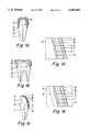
- FIGS. 1a-1e show cross-sections of natural teeth, one with an artificial tooth crown (FIG. 1a), one with an inlay (FIG. 1b), and one with a veneer (FIG. 1c) as well as partial cross-section of FIGS. 1a and 1b (FIG. 1d) and of FIG. 1c (FIG. 1e).
- A dental porcelain
- B core of densely sintered ceramic
- Y the outer surface of the core
- I the inner surface of the core
- C cement
- P the prepared surface of the tooth
- S the preparation border
- E enamel
- D dentin
- F pulp.
- FIG. 2 shows a cross-section of a bridge, which is cemented on two supporting teeth. These supporting teeth can have a vital abutment U 1 or an artificial abutment U 2 manufactured of a dental alloy, ceramic material or a strengthened polymer.
- the bridge in FIG. 2 contains two artificial dental crowns according to FIG. 1 with a pontic V between as replacement for a lost tooth.
- the bridge contains a core B having dental porcelain A.
- FIG. 3a shows a cross-section of an example of a press for individual cores for tooth crowns.
- FIG. 3b is a cross-section of a model K 1 of a preparation for a tooth crown enlarged considering the sintering shrinkage, S 1 is the preparation border, T is the top of the model, R is the bottom of the model and L is the enlarged surface of the preparation surface P.
- FIG. 3c shows a cross-section of a model K 2 which consists of K 1 with a coping of, e.g., wax, and Z is the outer surface of this coping.
- F is a tube
- G 1 is a plate with a cylinder G, which fits into F.
- H is a cylinder, which also fits into F.
- H, F, E, G and G 1 can be made of, e.g., metallic material.
- E is made of a viscous elastic material as well as J and X, which are impressions of K 2
- M is a cavity with space for ceramic powder.
- K 1 has been placed in X and P k is the force with which H is pressed against G.
- FIG. 4a shows a cross-section of an impression of two supporting teeth prepared for crowns and the gingiva between the teeth.
- c 1 and c 2 are the impressions of the preparations of the supporting teeth in a, which is the impression material.
- b 1 and b 2 are two parallel tubes firmly united to each other through b 3 .
- the inner surfaces of b 1 and b 2 consist of two cylinder surfaces with radii r 1 and r 2 (FIG. 4b). They are connected with e 1 -e 2 .
- w is the angle between the parts of b 1 and b 2 with radius r 1 and the surface with the cross-section e 1 -e 2 .
- q 1 and q 2 (FIG.
- FIGS. 4c and 4d show models n 1 and n 2 , respectively, of c 1 and c 2 made by pouring model material, e.g., plaster, in the tubes b 1 and b 2 and c 1 and c 2 .
- FIG. 5a shows N 1 and N 2 which are enlarged (compensated for the shrinkage during sintering) models of n 1 and n 2 in a mixture f with the holes g 1 and g 2 , manufactured so that the distance H between the central axes of g 1 and g 2 is h when enlarged considering the sintering shrinkage as well as the inner shape of the holes g 1 and g 2 , which are enlarged from the inner surface of the tubes b 1 and b 2 .
- Q 1 and Q 2 (FIG. 5b) are enlarged grooves q 1 and q 2 .
- FIG. 6 shows N 1 and N 2 placed in the fixture f.
- X is a tool made in a rubber material and M 1 is a cavity.
- artificial tooth restorations such as crowns, inlays, veneers or bridges are made as a core of densely sintered ceramic B with dental porcelain fired to the surface A.
- the tooth restorations are fixed to the prepared surfaces P by, e.g., cementing, as well as the bridge to the abutments U 1 and U 2 .
- the thin layer of cement C connects the prepared cavity walls P with that part of the surface of the inner surface of the core I, which has been made so that this surface D fits with great precision to the prepared surface P.
- dental porcelain can be fired.
- the layer of cement can have a thickness ⁇ 100 ⁇ m, preferably 25-50 ⁇ m.
- the cementing of the restorations can be made with, e.g., zinc phosphate cement, glass-ionomer cement or a resin cement A as known in the art.
- silane treat the inner surfaces I of the cores of the constructions, which will be joined with the prepared surfaces P of the tooth structure as well as it also can be advantageous to etch and treat the prepared surfaces P with a bonding resin before the cementation.
- a bridge can contain more supporting teeth and also more pontics in between.
- the supporting teeth can also be prepared for inlays or veneers. Veneers can be made both buccaly and lingually.
- the supporting teeth can also be implants with artificial abutments.
- the ceramic powder can be made by several methods well-known to the skilled artisan. Traditional powder metallurgical technique can be used, where the different components are mixed and ground under dry or wet conditions with water or an inorganic solvent, e.g., alcohols, as a grinding liquid. To the ceramic slurry, lubricants or other organic binders depending on the choice of forming method are added, when needed at a suitable time in the process.
- Traditional powder metallurgical technique can be used, where the different components are mixed and ground under dry or wet conditions with water or an inorganic solvent, e.g., alcohols, as a grinding liquid.
- an inorganic solvent e.g., alcohols
- the ceramic base material of the core preferably comprises one or several biocompatible oxides, with additives of carbides and nitrides with or without binders.
- biocompatible oxides which can form the base matrix for the ceramic body, are Al 2 O 3 , TiO 2 , MgO, ZrO 2 and ZrO 2 with additives of smaller amounts of up to 10 mole % of Y 2 O 3 or MgO (partly or totally stabilized ZrO 2 ).
- Additives can be present as particles with a size of ⁇ 25 ⁇ m, preferably ⁇ 10 ⁇ m, and/or as whiskers (hair-shaped single crystals) with a length of>10 ⁇ m, preferably>25 ⁇ m, and a length to diameter ratio>5, preferably>10, and/or fibers (polycrystalline) with a diameter>10 ⁇ m and/or single crystal platelets with an approximate diameter of 5-50 ⁇ m and a thickness of 1-10 ⁇ m.
- the amount of whiskers, fibers and/or platelets should not exceed 60 volume %.
- the ceramic material comprises>50% Al 2 O 3 with additives of conventional sintering aids.
- additives of conventional sintering aids In order to increase the strength ⁇ 25 weight %, preferably 3-12 weight %, of ZrO 2 , and/or 5-40 weight %, preferably 10-30 weight %, of SiC-, TiN- or ZrN-whiskers can be added.
- the ceramic material is sintered to closed porosity, which for an oxide material means at least 95% of theoretical density, but in order to ensure good mechanical strength, the material should preferably have a density over 98% with densities over 99.5% giving the best strength.
- additives e.g., 0.1-1 weight % of TiN and/or ZrN, will give Al 2 O 3 -based cores a faint yellow shade. Fe 2 O 3 gives a yellow-brown shade and MnO 2 gives a rose-colored shade. Of course, additives which give non-aesthetic effects should not be used.
- artificial ceramic tooth crowns, inlays, veneers and bridges can now be made from a ready-to-press powder with additions of lubricants and/or other organic binders.
- the powder is compacted against the body K 1 to form a core, which after sintering to full density fits to the prepared surface with a desired wall thickness.
- the sintering shrinkage has to be considered.
- the surface L must be enlarged in order to have the desired inner geometrical shape I of the green body which fits against the prepared surface P after the subsequent sintering process.
- the desired shape of the gap between the tooth crown and the prepared tooth for cementing the crown to the prepared tooth must also be considered. The size of this gap can be calculated, e.g., to be as small as possible, at the preparation border.
- the cores of the tooth crowns are manufactured by cold isostatic compaction, uniaxial pressing, slip casting, pressure casting, injection molding or by compacting the powder in another way, preferably by a cold isostatic technique against a body K 1 , which is shown in FIG. 3b.
- K 1 has a surface L, which is uniform with the surface P of the prepared tooth, on which the tooth crown or the veneer will fit.
- the body K 1 is manufactured by registering the prepared surface P or an artificial abutment directly in the mouth or from a model, e.g., in plaster, by a three-dimensional mechanical or optical method known to the skilled artisan.
- the registered surface is reproduced in an enlarged size L, e.g., with a computer-controlled milling machine.
- the enlargement is calculated from the shrinkage of the ceramic material during sintering to full density.
- the gap for cement is considered. It is important that the preparation border S 1 is evident. Below the preparation border S 1 , that is, between S 1 and the bottom R, the body K 1 is given such a shape that its surfaces converge to the occlusal part of the preparation. At the bottom R, the outer surface can be, e.g., cylindrical.
- the body K 1 can be manufactured of any suitable material, e.g., metal, graphite, polymers, etc.
- the surface L of the body K 1 is manufactured with a computer-controlled milling machine, which enlarges the registered tooth surface, and will, after compacting the powder against this surface L and sintering to full density, give the inner shape of the core I.
- the outer surface Y of the core is formed as follows: A body K 2 which is shown in FIG. 3c is milled with a computer-controlled milling machine from registered data from the prepared surface P of the registered tooth or the surface of the artificial abutment.
- K 2 contains the outer surface Z.
- the outer surface Z can be formed by forming a coping any easily moldable material, e.g., wax, or other material which easily can be formed against the body K 1 .
- the outer surface Z of this second body K 2 or K 1 with a coping in, e.g., wax, is used to form the outer shape Y of the core.
- An impression X is made from the body K 2 , or K 1 with a coping in, e.g., wax, in conventional viscous elastic material, e.g., a silicone.
- the compaction of the powder can be made with a tool as shown in FIG. 3a.
- This tool contains the impression X.
- K 1 fits into X from the bottom R to the preparation border S. Between the surface L of K 1 and X there is a cavity M.
- the impression X has such a shape as to fit into a body E, which can contain the viscous elastic material.
- the body E is placed into a tube F, which is put on G, which is a part of G 1 .
- the cylinder H with the same diameter as G is put into the tube F from the top.
- On top of the body E (which contains the impression X) and below the cylinder H is a lid J made of the same material as E.
- the manufacture of an individual core to a tooth crown can be made in the following way.
- the pressing tool is put together with the tube F on the cylinder G.
- the body E with the impression X is put into the tube F.
- Ready-to-press powder is filled into the cavity M and the body K 1 is fit into the impression X.
- K 1 fits into the impression X from the preparation border S 1 or just below and to the bottom R of the body K 1 .
- the lid J and the cylinder H are placed atop the assembly and the whole tool as shown in FIG. 3a is put into a press, e.g., a uniaxial hydraulic press.
- the cylinder H is pressed with the force P k in the tube F against the cylinder G in contact with the lid J and the powder is compacted against the body K 1 .
- the cylinder H, lid J and body K 1 are removed as well as the compacted shell which in some cases is attached to K 1 .
- the body K 1 should not contain any undercuts.
- the wall thickness of the green body is determined by the amount of powder put into the cavity M. After the pressing, the green body is adjusted at the preparation border S 1 and the wall thickness is controlled and adjusted before the sintering to full density.
- the wall thickness can be 0.5 mm, however, on certain places, wall thicknesses>0.5 mm may be needed in order to strengthen marginal ridges or for replacement of removed fillings. These thicknesses, if needed, can be readily determined by the skilled artisan.
- the core B is adjusted against the preparation border S of the plaster model in order to fit the surface I of the core B against the surface P of the prepared tooth or against the artificial abutment.
- dental porcelain A can be fired to the core for the manufacture of a tooth crown.
- a veneer can be manufactured in the same way as above.
- a core B of an inlay can also be manufactured by registering the surface P prepared for an inlay by a three-dimensional mechanical or optical method.
- the registered tooth surface is reproduced in an enlarged size of a suitable material, e.g., a metal, graphite or a polymer, by, e.g., use of a computer-controlled milling machine which enlarges the preparation.
- the amount of enlargement is calculated from the shrinkage of the ceramic material during sintering to full density and with a reduction for the cement.
- An impression X (FIG. 3a) can be manufactured in the same way as for a core of a tooth crown discussed above. Before the manufacturing of the impression X for an inlay, the enlarged preparation is over-filled with, e.g., wax.
- This enlarged model with the filled preparation cavity is used for the manufacture of the impression X in a conventional viscous elastic material, e.g., a silicone.
- a conventional viscous elastic material e.g., a silicone.
- This impression is placed in a press in the same way as described for FIG. 3a after the ceramic powder has been put in the cavity between the enlarged model and the impression X.
- the green body is removed.
- the preparation must not contain any undercuts.
- the green body is adjusted against the preparation border and space can be given if dental porcelain will be fired to the outer surfaces of the inlay, that means the surfaces which are not cemented against the prepared surfaces of the tooth. After the sintering of the core, some adjustment by grinding or polishing can be needed.
- a bridge can be manufactured by starting with the registration of the surfaces of the prepared tooth and the soft tissue in between by a three-dimensional mechanical or optical method. Registration of the mutual relationship of the supporting teeth can be done in the following way.
- An impression is made with conventional impression technique, e.g., with a silicone impression material. This impression is cast in, e.g., plaster.
- the prepared teeth and the jaw in between is registered by a three-dimensional mechanical or optical method.
- the prepared teeth and the tooth free jaw in between are reproduced in an enlarged size with, e.g., a computer-controlled milling machine.
- the enlargement is calculated from the shrinkage of the ceramic material during sintering to full density and with an additional space for the cement.
- the material of the enlarged models can again be, e.g., graphite, metal or a polymer.
- An impression as shown in FIG. 4a is made from the supporting teeth and the tissue in between with a conventional impression technique, e.g., with an impression material in, e.g., a silicone material a.
- FIG. 4a shows a cross-section of an impression.
- the tubes b 1 and b 2 are pressed into the impression material a.
- that part of the tubes pressed into the impression material can, e.g., have a chamfered edge.
- the tubes can also be fixed to the impression with, e.g., sticky wax.
- the tubes b 1 and b 2 can, e.g., have elliptic or circular cross-section with grooves q 1 and q 2 in the longitudinal axis in the internal surfaces of the tubes, and a step e 1 -e 2 , is clear from a cross-section parallel with the longitudinal axes.
- the tubes b 1 and b 2 have parallel longitudinal axes and surround the impressions c 1 and c 2 of the preparations of the supporting teeth in the impression material a.
- the tubes b 1 and b 2 are fixed to each other with b 3 .
- the impressions c 1 and c 2 are poured out in, e.g., plaster, which gives the models n 1 and n 2 shown in FIGS. 4c and d.
- the models n 1 and n 2 are registered with a three-dimensional mechanical or optical method and are reproduced in an enlarged size with, e.g., a computer-controlled milling machine.
- the amount of enlargement is calculated from the shrinkage of the ceramic material during sintering to full density and with an additional space for the cement above the preparation border S 1 of the models N 1 and N 2 .
- the material can again be, e.g., a metal, graphite or a polymer.
- These enlarged models N 1 and N 2 are put into a fixture f as shown in FIG. 5a.
- the fixture f contains a plate of a suitable material, e.g., a metal, which has two holes g 1 and g 2 .
- These holes have a geometry which is uniform with the internal surface of the tubes b 1 and b 2 and enlarged with the same enlargement factor considering the sintering shrinkage for the current ceramic powder.
- the distance H between the longitudinal axes of the holes is enlarged considering the sintering shrinkage of the ceramic material.
- FIG. 6 is an outline figure of the impression X.
- the models N 1 and N 2 put in the fixture f are placed in the impression X, manufactured in the same way as has been described for cores of single tooth crowns.
- the empty space M 1 which surrounds N 1 and N 2 , ceramic powder is placed and the tool is put in a pressing tool according to FIG. 3 and a compacting pressure P k is applied. The ceramic powder will be compacted against N 1 and N 2 and against the part of the fixture, which is situated between N 1 and N 2 .
- the green body is removed and the copings are adjusted at the preparation border and where the wall thickness needs reduction.
- the beam can be formed with, e.g., a milling cutter in a hand piece of a dental technician in order to give it a suitable form as a substructure of pontics.
- the core is sintered to full density. After sintering, some adjustments may be needed before the firing of dental porcelain to the core to have a bridge according to FIG. 2.
- the manufacturing of a bridge and the mutual relationship of the supporting teeth can be maintained after the enlargement in many other ways, e.g., before the impression a is cast, markers are placed in the impression in such a way that they give impressions in the different parts (the supporting teeth and the jaw in between) into which the plaster model is divided by sawing.
- the impressions of the markers in combination with enlarged markers can be used to have the mutual relationship of the supporting teeth after the enlargement.
- a bridge can also be manufactured, which is based on supporting teeth with preparations for a veneer on the buccal surface or a preparation on the lingual surface for a lingual plate.
- the manufacture of such a bridge can be made in the same way as has been described for a bridge with supporting teeth prepared for full crowns.
- a bridge can also be made for supporting teeth prepared for inlays.
- the manufacture of compaction tool and the compaction are made in the same way as described for a bridge with supporting teeth prepared for full crowns.
- the supporting teeth can have different types of preparations.
- a bridge based on supporting teeth prepared for inlays can also be made in densely sintered ceramic material by starting from, e.g., a plaster model of the prepared teeth and the jaw between.
- a beam can be made by using a light hardened polymer filled into the inlay preparations and connecting the preparations of the bridge. Before the hardening of the polymer, it is given such a shape that the inlays and the beam between have the desired form. After the light hardening of the polymer bridge, it is removed and is registered by a three-dimensional mechanical or optical method and reproduced in an enlarged size to a green body or a presintered ceramic body with, e.g., a computer-controlled milling machine. The enlargement is calculated from the shrinkage of the ceramic material during sintering to full density.
- FIG. 3a Another way of manufacturing a densely sintered shell, which after sintering to full density fits to a prepared tooth, is to make an impression of the enlarged body K 1 considering the sintering shrinkage and an additional space for the cement according to FIG. 3a.
- This impression is cast in plaster and a model K 3 in plaster is obtained from K 1 .
- An impression X is made according to FIG. 3a.
- Ceramic powder is compacted against the model K 3 with, e.g., the compaction tool described in FIG. 3a.
- the green body is presintered on the plaster model.
- Alumina is presintered at 800° C.-1100° C.
- the ceramic material shrinks much less and the presintered core can easily be removed, adjusted and sintered to full density.
- a densely sintered shell which after sintering to full density fits on a prepared tooth, is to make a slurry of ceramic powder mixed and ground under wet conditions with water or an organic solvent, e.g., an alcohol, as a grinding liquid.
- an organic solvent e.g., an alcohol
- lubricants or other organic binders are added to the ceramic slurry.
- the slurry of the ceramic powder is placed in some way, e.g., with a brush from the preparation border S 1 to the top T.
- the plaster model of K 1 (K 3 ) call also be dipped into a slurry of the ceramic powder.
- a suction cup can be applied to the bottom surface R and by a suction cup a negative pressure is applied during the dipping of the body K 3 into the slurry as described in U.S. patent application Ser. No. 07/828,952, the disclosure of which is hereby incorporated by reference.
- the ceramic particles will be packed against the plaster model when this model absorbs the water from the slurry. In this way, the ceramic powder is compacted against the plaster model and the body compacted in this way can be adjusted at the preparation border S 1 and adjusted to desired shape and shell thickness of the core.
- the green body is presintered on the plaster model.
- the presintered body will be too big for the plaster model and can be removed for any adjustment and sintering to full density.
- plaster instead of plaster, other porous materials can be used provided that they can be used provided that they can be used as sintering support during the presintering.
- Bridges can be manufactured with the above described slip casting method by making an impression from N 1 and N 2 in the fixture f, FIG. 5a, and cast in, e.g., plaster.
- a support for the slurry to make the substructure for the pontics is built up with, e.g., wax, on the fixture between N 1 and N 2 .
- An impression is made of the fixture with the support N 1 and N 2 for the pontics, which is cast in plaster.
- the plaster model is fixed to a plate in some ceramic material and is divided into three parts, N 1 , pontic and N 2 . The three parts have the same mutual relationship as before the separation.
- a slurry is place in the same manner as was described for cores for single tooth crowns.
- the separated and fixed plaster model with the ceramic slurry is presintered and the presintered bridge core can, if needed, be adjusted before the sintering to full density.
- Another way of manufacturing a core of a bridge is to compact ceramic powder with a tool shown in FIG. 6 against N 1 and N 2 in the fixture f according to FIG. 5a or against a plaster model according to FIG. 5a fixed and separated into three parts.
- the tool is placed in a compaction tool similar to that shown in FIG. 3a after the ceramic powder has been placed into M 1 .
- the green body manufactured in this way is adjusted before the presintering. After presintering, the body can have any adjustment before the sintering to full density in a known way.
Abstract
Description
Claims (8)
Applications Claiming Priority (2)
| Application Number | Priority Date | Filing Date | Title |
|---|---|---|---|
| SE9201927-2 | 1992-06-23 | ||
| SE9201927A SE470346B (en) | 1992-06-23 | 1992-06-23 | Method for making ceramic artificial tooth restorations |
Publications (1)
| Publication Number | Publication Date |
|---|---|
| US5342201A true US5342201A (en) | 1994-08-30 |
Family
ID=20386580
Family Applications (1)
| Application Number | Title | Priority Date | Filing Date |
|---|---|---|---|
| US08/079,607 Expired - Lifetime US5342201A (en) | 1992-06-23 | 1993-06-22 | Method of manufacturing ceramic artifical tooth restorations |
Country Status (9)
| Country | Link |
|---|---|
| US (1) | US5342201A (en) |
| EP (1) | EP0580565B1 (en) |
| AT (1) | ATE170069T1 (en) |
| DE (1) | DE69320563T2 (en) |
| DK (1) | DK0580565T3 (en) |
| ES (1) | ES2119881T3 (en) |
| FI (1) | FI932910A (en) |
| NO (1) | NO306927B1 (en) |
| SE (1) | SE470346B (en) |
Cited By (61)
| Publication number | Priority date | Publication date | Assignee | Title |
|---|---|---|---|---|
| DE19511396A1 (en) * | 1995-03-28 | 1996-10-02 | Arnold Wohlwend | Process for producing a prosthetic tooth inlay or a prosthetic tooth crown |
| US5624261A (en) * | 1995-08-09 | 1997-04-29 | Wiedenfeld; Kenneth R. | Composite resin veneer |
| US5788498A (en) * | 1995-12-19 | 1998-08-04 | Ivoclar Ag | Method for manufacturing dental crowns |
| US5827063A (en) * | 1997-04-07 | 1998-10-27 | Greenstein; Jean | Method of making dental restoration employing preforms |
| US5857853A (en) * | 1993-07-26 | 1999-01-12 | Nobel Biocare Ab | Method of manufacturing a prosthesis to be fixed to implants in the jawbone of a patient, and a system for manufacturing such prostheses |
| US6238601B1 (en) | 1997-09-12 | 2001-05-29 | Sandvik Ab | Method for making ceramic artificial dental bridges |
| US6354836B1 (en) * | 1998-08-20 | 2002-03-12 | Jeneric/Pentron, Inc. | Methods of producing dental restorations using CAD/CAM and manufactures thereof |
| US6413660B1 (en) * | 1998-06-12 | 2002-07-02 | Jeneric/Pentron, Inc. | High-strength dental restorations |
| US20020090525A1 (en) * | 1999-01-08 | 2002-07-11 | Rusin Richard P. | Dental mill blanks |
| US6488503B1 (en) | 1999-12-21 | 2002-12-03 | Dentsply Research & Development Corp. | Prosthetic teeth and method of making therefor |
| US6607386B1 (en) * | 1998-09-11 | 2003-08-19 | Nobel Biocare Ab | Method and device for, and use of, a dental product |
| US6689202B2 (en) * | 2000-07-21 | 2004-02-10 | Jeneric/Pentron Incorporated | Molds for the manufacture of a dental restoration and methods of making dental restorations |
| AU776793B2 (en) * | 1999-03-10 | 2004-09-23 | Gc Corporation | Glass powder for glass ionomer cement |
| US20040197738A1 (en) * | 2001-08-03 | 2004-10-07 | Kiyoko Ban | Dental ceramic frame, preparation of the same and dental prosthesis comprising the frame |
| US20040204787A1 (en) * | 2003-04-03 | 2004-10-14 | Avi Kopelman | Method and system for fabricating a dental coping, and a coping fabricated thereby |
| US20040261304A1 (en) * | 2003-06-27 | 2004-12-30 | Edwards Christopher M. | Decorative tiles for attachment to strand meshes |
| US20050127544A1 (en) * | 1998-06-12 | 2005-06-16 | Dmitri Brodkin | High-strength dental restorations |
| US20050261795A1 (en) * | 2004-05-21 | 2005-11-24 | Eastman Kodak Company | Method of making ceramic dental restorations |
| US20060174653A1 (en) * | 2002-01-03 | 2006-08-10 | Nobel Biocare Ab | Method for making ceramic artificial dental bridges |
| US20060194896A1 (en) * | 2004-05-26 | 2006-08-31 | Sun Benjamin J | Low shrinkage dental material and method |
| US20060234188A1 (en) * | 2005-04-15 | 2006-10-19 | Hunt Peter R | High strength substructure reinforcement for crowns and bridges |
| US20060257823A1 (en) * | 2005-05-13 | 2006-11-16 | Sirona Dental Systems Gmbh | Method of producing a dental prosthetic item, and dental prosthetic item thus produced |
| US20070233299A1 (en) * | 2004-12-02 | 2007-10-04 | Cadent Ltd. | System and method for manufacturing a dental prosthesis and a dental prosthesis manufactured thereby |
| US20070281284A1 (en) * | 2003-11-12 | 2007-12-06 | Matts Andersson | System And Arrangement For Producing A Dental Replacement Component, And Such A Component |
| CN100374088C (en) * | 1998-03-17 | 2008-03-12 | 苏黎士高等院校非金属材料联盟 | Dental crowns and/or dental bridges |
| KR100837571B1 (en) | 2007-01-25 | 2008-06-11 | 박수강 | A core for dental and manufacturing method thereof |
| EP1974689A1 (en) * | 2007-03-30 | 2008-10-01 | GC Corporation | Production method of zirconia-made implant bridge |
| US20090255813A1 (en) * | 2006-03-24 | 2009-10-15 | Stefan Wolz Ohg | Process for Producing Articles From Ceramic or Metal by Electrophoretic Free Forming |
| US20100003635A1 (en) * | 2004-12-21 | 2010-01-07 | Johan Feith | Dental implant |
| US20100081109A1 (en) * | 2006-12-22 | 2010-04-01 | Thommen Medical Ag | Dental implant and method for the production thereof |
| EP2172168A1 (en) | 2008-10-01 | 2010-04-07 | 3M Innovative Properties Company | Dental appliance, process for producing a dental appliance and use thereof |
| US20100291509A1 (en) * | 2007-06-07 | 2010-11-18 | Nobel Biocare Services Ag | Method and arrangement for forming a dental bridge |
| US20100323327A1 (en) * | 2007-06-07 | 2010-12-23 | Nobel Biocare Services Ag | Method of producing a dental product |
| US20110006451A1 (en) * | 2007-12-17 | 2011-01-13 | Nobel Biocare Services Ag | Method of producing a dental ceramic product |
| US8075312B2 (en) | 2005-08-30 | 2011-12-13 | Zimmer Dental, Inc. | Dental implant with improved osseointegration features |
| KR20120012968A (en) * | 2009-03-25 | 2012-02-13 | 오라티오 비.브이. | Veneered dental restoration with a controlled shade |
| CN102370525A (en) * | 2011-10-31 | 2012-03-14 | 山东新华医疗器械股份有限公司 | Cantilever type workbench mechanism of processing equipment of full automatic engraving and milling machine |
| US20120156651A1 (en) * | 2010-12-20 | 2012-06-21 | Levi Jack | Restoration of anterior endodontically treated teeth |
| US8231387B2 (en) | 2008-07-02 | 2012-07-31 | Zimmer, Inc. | Porous implant with non-porous threads |
| US20130244207A1 (en) * | 2010-11-12 | 2013-09-19 | Sang Choon Cho | Mold For Dental Copings And Copings Produced By Using The Mold |
| US8562346B2 (en) | 2005-08-30 | 2013-10-22 | Zimmer Dental, Inc. | Dental implant for a jaw with reduced bone volume and improved osseointegration features |
| US8562348B2 (en) | 2008-07-02 | 2013-10-22 | Zimmer Dental, Inc. | Modular implant with secured porous portion |
| US8602782B2 (en) | 2009-11-24 | 2013-12-10 | Zimmer Dental, Inc. | Porous implant device with improved core |
| US8721938B2 (en) | 2009-09-30 | 2014-05-13 | 3M Innovative Properties Company | Methods for making layered dental appliances |
| US8814567B2 (en) | 2005-05-26 | 2014-08-26 | Zimmer Dental, Inc. | Dental implant prosthetic device with improved osseointegration and esthetic features |
| US8813364B2 (en) | 2009-12-18 | 2014-08-26 | 3M Innovative Properties Company | Methods for making layered dental appliances |
| US8834752B2 (en) | 2009-09-30 | 2014-09-16 | 3M Innovative Properties Company | Systems and methods for making layered dental appliances |
| US8851891B2 (en) | 2008-11-06 | 2014-10-07 | Zimmer Dental, Inc. | Expandable bone implant |
| US8899982B2 (en) | 2008-07-02 | 2014-12-02 | Zimmer Dental, Inc. | Implant with structure for securing a porous portion |
| US9039947B2 (en) | 2009-09-30 | 2015-05-26 | 3M Innovative Properties Company | Methods for making layered dental appliances from the outside in |
| US9045378B2 (en) | 2009-06-19 | 2015-06-02 | Nobel Biocare Services Ag | Dental application coating |
| US9095396B2 (en) | 2008-07-02 | 2015-08-04 | Zimmer Dental, Inc. | Porous implant with non-porous threads |
| US20150265380A1 (en) * | 2004-02-06 | 2015-09-24 | Zircore, Llc | Companion engineering and manufacturing processes (cemp) to optimize multi-layered zirconia crowns |
| US9149345B2 (en) | 2007-08-30 | 2015-10-06 | Zimmer Dental, Inc. | Multiple root implant |
| WO2015168332A3 (en) * | 2014-04-30 | 2015-12-17 | Osseodyne Surgical Solutions, Llc | Osseointegrative surgical implant |
| US9707058B2 (en) | 2009-07-10 | 2017-07-18 | Zimmer Dental, Inc. | Patient-specific implants with improved osseointegration |
| US20190307537A1 (en) * | 2016-12-08 | 2019-10-10 | John Fung | Dental Prosthetic Moulds and Moulding Methods |
| US20210177544A1 (en) * | 2018-08-14 | 2021-06-17 | Dentsply Sirona Inc. | Dental prosthesis |
| US20210401543A1 (en) * | 2017-11-06 | 2021-12-30 | 3M Innovative Properties Company | Dental crown having a highly retentive coating and method for making the same |
| US11253436B2 (en) * | 2016-04-28 | 2022-02-22 | 3M Innovative Properties Company | Method of making a dental restoration |
| US20230248487A1 (en) * | 2022-02-10 | 2023-08-10 | Exocad Gmbh | Testing model for testing fitting of a dental restoration |
Families Citing this family (13)
| Publication number | Priority date | Publication date | Assignee | Title |
|---|---|---|---|---|
| DE19503637C2 (en) * | 1995-02-05 | 1998-04-09 | Hahn Rainer | Tooth restoration part made of ceramic material and method for producing such |
| FR2735679B1 (en) * | 1995-06-23 | 1997-12-05 | Aten Dev | PROCESS FOR PRODUCING A DENTAL PROSTHESIS |
| WO1997030654A1 (en) * | 1996-02-22 | 1997-08-28 | Arnold Wohlwend | Implantable tooth replacement, abutment therefor and process for making abutments |
| CA2275368A1 (en) * | 1996-12-20 | 1998-07-02 | Jean-Marc Perot | Method for producing a dental prosthesis |
| US6033222A (en) * | 1997-04-25 | 2000-03-07 | Schneider, Ii; George J. | Method of fabrication of translucent dental restorations without opacious substructures |
| EP0943295A1 (en) * | 1998-03-17 | 1999-09-22 | Eidgenössische Technische Hochschule Zürich | Method for the manufactoring of tooth crowns and/or dental bridges |
| EP1087720B1 (en) | 1999-04-16 | 2004-04-07 | Kaltenbach & Voigt GmbH & Co. KG | Method for producing ceramic medical, dental medical, technical dental and technical parts |
| WO2001041670A1 (en) * | 1999-12-07 | 2001-06-14 | Inocermic Gesellschaft für innovative Keramik mbH | Method for producing a ceramic dental prosthesis and a high-strength ceramic dental prosthesis produced according thereto |
| DE10002921C2 (en) * | 2000-01-25 | 2003-11-20 | Stefan Wolz | Process for the production of all-ceramic bridges |
| WO2003035014A1 (en) * | 2001-10-25 | 2003-05-01 | Vita Zahnfabrik H. Rauter Gmbh & Co. Kg | System for producing a veneering ceramic |
| US9259508B2 (en) | 2003-03-07 | 2016-02-16 | Louis A. Serafin, Jr. Trust | Ceramic manufactures |
| CA2517623C (en) * | 2003-03-07 | 2012-10-02 | Louis A. Serafin, Jr. | Ceramic manufactures |
| WO2009135735A2 (en) | 2008-05-08 | 2009-11-12 | Degudent Gmbh | Method for determining 3d data from at least one prepared maxillary area |
Citations (8)
| Publication number | Priority date | Publication date | Assignee | Title |
|---|---|---|---|---|
| US4411626A (en) * | 1980-01-31 | 1983-10-25 | Becker Dental-Labor Gmbh | Process and apparatus for preparing a crown portion to be fixed on a tooth |
| US4478580A (en) * | 1982-02-05 | 1984-10-23 | Barrut Luc P | Process and apparatus for treating teeth |
| US4661071A (en) * | 1984-04-03 | 1987-04-28 | Denpac Corp. | Vacuum sintered powder alloy dental prosthetic device and oven to form same |
| EP0241384A2 (en) * | 1986-04-11 | 1987-10-14 | Tyszblat Sadoun, Michèle | Method of producing dental prosthesis and prosthesis obtained by this method |
| US4937928A (en) * | 1987-10-07 | 1990-07-03 | Elephant Edelmetaal B.V. | Method of making a dental crown for a dental preparation by means of a CAD-CAM system |
| US5080589A (en) * | 1988-12-20 | 1992-01-14 | Sandvik Ab | Artificial tooth crowns |
| US5106303A (en) * | 1989-03-23 | 1992-04-21 | Sandvik Ab | Methods of making artificial tooth onlays and inlays |
| US5217375A (en) * | 1989-03-23 | 1993-06-08 | Sandvik Ab | Artificial onlay tooth crowns and inlays |
-
1992
- 1992-06-23 SE SE9201927A patent/SE470346B/en not_active IP Right Cessation
-
1993
- 1993-06-21 ES ES93850137T patent/ES2119881T3/en not_active Expired - Lifetime
- 1993-06-21 EP EP93850137A patent/EP0580565B1/en not_active Expired - Lifetime
- 1993-06-21 DK DK93850137T patent/DK0580565T3/en active
- 1993-06-21 AT AT93850137T patent/ATE170069T1/en active
- 1993-06-21 DE DE69320563T patent/DE69320563T2/en not_active Expired - Lifetime
- 1993-06-22 NO NO932298A patent/NO306927B1/en unknown
- 1993-06-22 US US08/079,607 patent/US5342201A/en not_active Expired - Lifetime
- 1993-06-23 FI FI932910A patent/FI932910A/en not_active Application Discontinuation
Patent Citations (8)
| Publication number | Priority date | Publication date | Assignee | Title |
|---|---|---|---|---|
| US4411626A (en) * | 1980-01-31 | 1983-10-25 | Becker Dental-Labor Gmbh | Process and apparatus for preparing a crown portion to be fixed on a tooth |
| US4478580A (en) * | 1982-02-05 | 1984-10-23 | Barrut Luc P | Process and apparatus for treating teeth |
| US4661071A (en) * | 1984-04-03 | 1987-04-28 | Denpac Corp. | Vacuum sintered powder alloy dental prosthetic device and oven to form same |
| EP0241384A2 (en) * | 1986-04-11 | 1987-10-14 | Tyszblat Sadoun, Michèle | Method of producing dental prosthesis and prosthesis obtained by this method |
| US4937928A (en) * | 1987-10-07 | 1990-07-03 | Elephant Edelmetaal B.V. | Method of making a dental crown for a dental preparation by means of a CAD-CAM system |
| US5080589A (en) * | 1988-12-20 | 1992-01-14 | Sandvik Ab | Artificial tooth crowns |
| US5106303A (en) * | 1989-03-23 | 1992-04-21 | Sandvik Ab | Methods of making artificial tooth onlays and inlays |
| US5217375A (en) * | 1989-03-23 | 1993-06-08 | Sandvik Ab | Artificial onlay tooth crowns and inlays |
Cited By (108)
| Publication number | Priority date | Publication date | Assignee | Title |
|---|---|---|---|---|
| US5857853A (en) * | 1993-07-26 | 1999-01-12 | Nobel Biocare Ab | Method of manufacturing a prosthesis to be fixed to implants in the jawbone of a patient, and a system for manufacturing such prostheses |
| US6287119B1 (en) | 1993-07-26 | 2001-09-11 | Nobel Biocare Ab | Method of manufacturing a prosthesis to be fixed to implants in the jawbone of a patient, and a system for manufacturing such prostheses |
| DE19511396A1 (en) * | 1995-03-28 | 1996-10-02 | Arnold Wohlwend | Process for producing a prosthetic tooth inlay or a prosthetic tooth crown |
| US5624261A (en) * | 1995-08-09 | 1997-04-29 | Wiedenfeld; Kenneth R. | Composite resin veneer |
| US5788498A (en) * | 1995-12-19 | 1998-08-04 | Ivoclar Ag | Method for manufacturing dental crowns |
| US5827063A (en) * | 1997-04-07 | 1998-10-27 | Greenstein; Jean | Method of making dental restoration employing preforms |
| US6238601B1 (en) | 1997-09-12 | 2001-05-29 | Sandvik Ab | Method for making ceramic artificial dental bridges |
| CN100374088C (en) * | 1998-03-17 | 2008-03-12 | 苏黎士高等院校非金属材料联盟 | Dental crowns and/or dental bridges |
| US20050127544A1 (en) * | 1998-06-12 | 2005-06-16 | Dmitri Brodkin | High-strength dental restorations |
| US6413660B1 (en) * | 1998-06-12 | 2002-07-02 | Jeneric/Pentron, Inc. | High-strength dental restorations |
| US20020155412A1 (en) * | 1998-08-20 | 2002-10-24 | Carlino Panzera | Methods of producing dental restorations using CAD/CAM and manufactures thereof |
| US7011522B2 (en) * | 1998-08-20 | 2006-03-14 | Pentron Ceramics, Inc. | Methods of producing dental restorations using CAD/CAM and manufactures thereof |
| US6354836B1 (en) * | 1998-08-20 | 2002-03-12 | Jeneric/Pentron, Inc. | Methods of producing dental restorations using CAD/CAM and manufactures thereof |
| US6607386B1 (en) * | 1998-09-11 | 2003-08-19 | Nobel Biocare Ab | Method and device for, and use of, a dental product |
| US20030157357A1 (en) * | 1999-01-08 | 2003-08-21 | 3M Innovative Properties Company | Dental mill blanks |
| US20110045436A1 (en) * | 1999-01-08 | 2011-02-24 | 3M Innovative Properties Company | Dental mill blanks |
| US7255562B2 (en) | 1999-01-08 | 2007-08-14 | 3M Innovative Properties Company | Dental mill blanks |
| US8317516B2 (en) | 1999-01-08 | 2012-11-27 | 3M Innovative Properties Company | Dental mill blanks |
| US7845947B2 (en) | 1999-01-08 | 2010-12-07 | 3M Innovative Properties Company | Dental mill blanks |
| US20020090525A1 (en) * | 1999-01-08 | 2002-07-11 | Rusin Richard P. | Dental mill blanks |
| AU776793B2 (en) * | 1999-03-10 | 2004-09-23 | Gc Corporation | Glass powder for glass ionomer cement |
| US6488503B1 (en) | 1999-12-21 | 2002-12-03 | Dentsply Research & Development Corp. | Prosthetic teeth and method of making therefor |
| US20040245664A1 (en) * | 2000-07-21 | 2004-12-09 | Carlino Panzera | Method of making a dental restoration |
| US20070056467A1 (en) * | 2000-07-21 | 2007-03-15 | Pentron Ceramics, Inc. | Method of making a dental restoration |
| US6689202B2 (en) * | 2000-07-21 | 2004-02-10 | Jeneric/Pentron Incorporated | Molds for the manufacture of a dental restoration and methods of making dental restorations |
| US7943068B2 (en) * | 2000-07-21 | 2011-05-17 | Ivoclar Vivadent, Inc. | Method of making a dental restoration |
| US20040197738A1 (en) * | 2001-08-03 | 2004-10-07 | Kiyoko Ban | Dental ceramic frame, preparation of the same and dental prosthesis comprising the frame |
| US20060174653A1 (en) * | 2002-01-03 | 2006-08-10 | Nobel Biocare Ab | Method for making ceramic artificial dental bridges |
| US7600398B2 (en) | 2002-01-03 | 2009-10-13 | Nobel Biocare Ab | Method for making ceramic artificial dental bridges |
| US7996099B2 (en) | 2003-04-03 | 2011-08-09 | Cadent Ltd. | Method and system for fabricating a dental coping, and a coping fabricated thereby |
| US20060271229A1 (en) * | 2003-04-03 | 2006-11-30 | Cadent, Ltd. | Method and system for fabricating a dental coping, and a coping fabricated thereby |
| US6957118B2 (en) | 2003-04-03 | 2005-10-18 | Cadent Ltd. | Method and system for fabricating a dental coping, and a coping fabricated thereby |
| US20040204787A1 (en) * | 2003-04-03 | 2004-10-14 | Avi Kopelman | Method and system for fabricating a dental coping, and a coping fabricated thereby |
| US7110844B2 (en) | 2003-04-03 | 2006-09-19 | Cadent Ltd. | Method and system for fabricating a dental prosthesis, and a prosthesis wax model |
| US20060004477A1 (en) * | 2003-04-03 | 2006-01-05 | Cadent Ltd. | Method and system for fabricating a dental coping, and a coping fabricated thereby |
| US7383094B2 (en) | 2003-04-03 | 2008-06-03 | Cadent Ltd. | Method for CNC milling a wax model of a dental prosthesis or coping |
| US20080208382A1 (en) * | 2003-04-03 | 2008-08-28 | Cadent Ltd. | Method and system for fabricating a dental coping, and a coping fabricated thereby |
| US20040261304A1 (en) * | 2003-06-27 | 2004-12-30 | Edwards Christopher M. | Decorative tiles for attachment to strand meshes |
| US20070281284A1 (en) * | 2003-11-12 | 2007-12-06 | Matts Andersson | System And Arrangement For Producing A Dental Replacement Component, And Such A Component |
| US7925374B2 (en) * | 2003-11-12 | 2011-04-12 | Nobel Biocare Services Ag | System and arrangement for producing a dental replacement component, and such a component |
| US20150265380A1 (en) * | 2004-02-06 | 2015-09-24 | Zircore, Llc | Companion engineering and manufacturing processes (cemp) to optimize multi-layered zirconia crowns |
| US20050261795A1 (en) * | 2004-05-21 | 2005-11-24 | Eastman Kodak Company | Method of making ceramic dental restorations |
| US20060194896A1 (en) * | 2004-05-26 | 2006-08-31 | Sun Benjamin J | Low shrinkage dental material and method |
| US7689310B2 (en) | 2004-12-02 | 2010-03-30 | Cadent Ltd. | System and method for manufacturing a dental prosthesis and a dental prosthesis manufactured thereby |
| US20070233299A1 (en) * | 2004-12-02 | 2007-10-04 | Cadent Ltd. | System and method for manufacturing a dental prosthesis and a dental prosthesis manufactured thereby |
| US11197739B2 (en) | 2004-12-02 | 2021-12-14 | Align Technology, Inc. | System and method for manufacturing a dental prosthesis and a dental prosthesis manufactured thereby |
| US8909363B2 (en) | 2004-12-02 | 2014-12-09 | Align Technology, Inc. | System and method for manufacturing a dental prosthesis and a dental prosthesis manufactured thereby |
| US20100167238A1 (en) * | 2004-12-02 | 2010-07-01 | Cadent Ltd. | System and method for manufacturing a dental prosthesis and a dental prosthesis manufactured thereby |
| US10059059B2 (en) | 2004-12-02 | 2018-08-28 | Align Technology, Inc. | System and method for manufacturing a dental prosthesis and a dental prosthesis manufactured thereby |
| US10406753B2 (en) | 2004-12-02 | 2019-09-10 | Align Technology, Inc. | System and method for manufacturing a dental prosthesis and a dental prosthesis manufactured thereby |
| US20100003635A1 (en) * | 2004-12-21 | 2010-01-07 | Johan Feith | Dental implant |
| US7690920B2 (en) * | 2005-04-15 | 2010-04-06 | Hunt Peter R | High strength substructure reinforcement for crowns and bridges |
| US20060234188A1 (en) * | 2005-04-15 | 2006-10-19 | Hunt Peter R | High strength substructure reinforcement for crowns and bridges |
| US20060257823A1 (en) * | 2005-05-13 | 2006-11-16 | Sirona Dental Systems Gmbh | Method of producing a dental prosthetic item, and dental prosthetic item thus produced |
| US8235722B2 (en) * | 2005-05-13 | 2012-08-07 | Sirona Dental Systems Gmbh | Method of producing a dental prosthetic item, and dental prosthetic item thus produced |
| US8814567B2 (en) | 2005-05-26 | 2014-08-26 | Zimmer Dental, Inc. | Dental implant prosthetic device with improved osseointegration and esthetic features |
| US8075312B2 (en) | 2005-08-30 | 2011-12-13 | Zimmer Dental, Inc. | Dental implant with improved osseointegration features |
| US10070945B2 (en) | 2005-08-30 | 2018-09-11 | Zimmer Dental, Inc. | Dental implant for a jaw with reduced bone volume and improved osseointegration features |
| US8562346B2 (en) | 2005-08-30 | 2013-10-22 | Zimmer Dental, Inc. | Dental implant for a jaw with reduced bone volume and improved osseointegration features |
| US8899981B2 (en) | 2005-08-30 | 2014-12-02 | Zimmer Dental, Inc. | Dental implant for a jaw with reduced bone volume and improved osseointegration features |
| US20090255813A1 (en) * | 2006-03-24 | 2009-10-15 | Stefan Wolz Ohg | Process for Producing Articles From Ceramic or Metal by Electrophoretic Free Forming |
| US8671572B2 (en) * | 2006-12-22 | 2014-03-18 | Thommen Medical Ag | Method for the production of a dental implant |
| US20100081109A1 (en) * | 2006-12-22 | 2010-04-01 | Thommen Medical Ag | Dental implant and method for the production thereof |
| KR100837571B1 (en) | 2007-01-25 | 2008-06-11 | 박수강 | A core for dental and manufacturing method thereof |
| EP1974689A1 (en) * | 2007-03-30 | 2008-10-01 | GC Corporation | Production method of zirconia-made implant bridge |
| US20080241794A1 (en) * | 2007-03-30 | 2008-10-02 | Gc Corporation | Production method of zirconia-made implant bridge |
| US8231825B2 (en) | 2007-06-07 | 2012-07-31 | Nobel Biocare Services Ag | Method of producing a dental product |
| US10449020B2 (en) | 2007-06-07 | 2019-10-22 | Nobel Biocare Services Ag | Method and arrangement for forming a dental bridge |
| US20100291509A1 (en) * | 2007-06-07 | 2010-11-18 | Nobel Biocare Services Ag | Method and arrangement for forming a dental bridge |
| US20100323327A1 (en) * | 2007-06-07 | 2010-12-23 | Nobel Biocare Services Ag | Method of producing a dental product |
| US9561090B2 (en) | 2007-06-07 | 2017-02-07 | Nobel Biocare Services Ag | Method of producing a dental product |
| US9149345B2 (en) | 2007-08-30 | 2015-10-06 | Zimmer Dental, Inc. | Multiple root implant |
| US20110006451A1 (en) * | 2007-12-17 | 2011-01-13 | Nobel Biocare Services Ag | Method of producing a dental ceramic product |
| US8562348B2 (en) | 2008-07-02 | 2013-10-22 | Zimmer Dental, Inc. | Modular implant with secured porous portion |
| US8231387B2 (en) | 2008-07-02 | 2012-07-31 | Zimmer, Inc. | Porous implant with non-porous threads |
| US9066771B2 (en) | 2008-07-02 | 2015-06-30 | Zimmer Dental, Inc. | Modular implant with secured porous portion |
| US9095396B2 (en) | 2008-07-02 | 2015-08-04 | Zimmer Dental, Inc. | Porous implant with non-porous threads |
| US8899982B2 (en) | 2008-07-02 | 2014-12-02 | Zimmer Dental, Inc. | Implant with structure for securing a porous portion |
| US20110151411A1 (en) * | 2008-10-01 | 2011-06-23 | 3M Innovative Properties Company | Dental appliance, process for producing a dental appliance and use thereof |
| US8865033B2 (en) | 2008-10-01 | 2014-10-21 | 3M Innovative Properties Company | Process for producing a dental appliance |
| EP2172168A1 (en) | 2008-10-01 | 2010-04-07 | 3M Innovative Properties Company | Dental appliance, process for producing a dental appliance and use thereof |
| US8851891B2 (en) | 2008-11-06 | 2014-10-07 | Zimmer Dental, Inc. | Expandable bone implant |
| US9744007B2 (en) | 2008-11-06 | 2017-08-29 | Zimmer Dental, Inc. | Expandable bone implant |
| US8828287B2 (en) * | 2009-03-25 | 2014-09-09 | Oratio B.V. | Veneered dental restoration with a controlled shade |
| KR20120012968A (en) * | 2009-03-25 | 2012-02-13 | 오라티오 비.브이. | Veneered dental restoration with a controlled shade |
| US20120139142A1 (en) * | 2009-03-25 | 2012-06-07 | Oratio B.V. | Veneered dental restoration with a controlled shade |
| US9045378B2 (en) | 2009-06-19 | 2015-06-02 | Nobel Biocare Services Ag | Dental application coating |
| US9707058B2 (en) | 2009-07-10 | 2017-07-18 | Zimmer Dental, Inc. | Patient-specific implants with improved osseointegration |
| US9039947B2 (en) | 2009-09-30 | 2015-05-26 | 3M Innovative Properties Company | Methods for making layered dental appliances from the outside in |
| US8834752B2 (en) | 2009-09-30 | 2014-09-16 | 3M Innovative Properties Company | Systems and methods for making layered dental appliances |
| US8721938B2 (en) | 2009-09-30 | 2014-05-13 | 3M Innovative Properties Company | Methods for making layered dental appliances |
| US8602782B2 (en) | 2009-11-24 | 2013-12-10 | Zimmer Dental, Inc. | Porous implant device with improved core |
| US10687919B2 (en) | 2009-11-24 | 2020-06-23 | Zimmer Dental, Inc. | Porous implant device with improved core |
| US9439738B2 (en) | 2009-11-24 | 2016-09-13 | Zimmer Dental, Inc. | Porous implant device with improved core |
| US9901424B2 (en) | 2009-11-24 | 2018-02-27 | Zimmer Dental, Inc. | Porous implant device with improved core |
| US8813364B2 (en) | 2009-12-18 | 2014-08-26 | 3M Innovative Properties Company | Methods for making layered dental appliances |
| US20130244207A1 (en) * | 2010-11-12 | 2013-09-19 | Sang Choon Cho | Mold For Dental Copings And Copings Produced By Using The Mold |
| US9168109B2 (en) * | 2010-11-12 | 2015-10-27 | Ebi Co., Ltd. | Mold for dental copings and copings produced by using the mold |
| US20120156651A1 (en) * | 2010-12-20 | 2012-06-21 | Levi Jack | Restoration of anterior endodontically treated teeth |
| CN102370525B (en) * | 2011-10-31 | 2013-07-31 | 山东新华医疗器械股份有限公司 | Cantilever type workbench mechanism of processing equipment of full automatic engraving and milling machine |
| CN102370525A (en) * | 2011-10-31 | 2012-03-14 | 山东新华医疗器械股份有限公司 | Cantilever type workbench mechanism of processing equipment of full automatic engraving and milling machine |
| WO2015168332A3 (en) * | 2014-04-30 | 2015-12-17 | Osseodyne Surgical Solutions, Llc | Osseointegrative surgical implant |
| US11141244B2 (en) | 2014-04-30 | 2021-10-12 | Ceramedica, Inc. | Osseointegrative surgical implant |
| US11253436B2 (en) * | 2016-04-28 | 2022-02-22 | 3M Innovative Properties Company | Method of making a dental restoration |
| US20190307537A1 (en) * | 2016-12-08 | 2019-10-10 | John Fung | Dental Prosthetic Moulds and Moulding Methods |
| US20210401543A1 (en) * | 2017-11-06 | 2021-12-30 | 3M Innovative Properties Company | Dental crown having a highly retentive coating and method for making the same |
| US20210177544A1 (en) * | 2018-08-14 | 2021-06-17 | Dentsply Sirona Inc. | Dental prosthesis |
| US20230248487A1 (en) * | 2022-02-10 | 2023-08-10 | Exocad Gmbh | Testing model for testing fitting of a dental restoration |
Also Published As
| Publication number | Publication date |
|---|---|
| EP0580565B1 (en) | 1998-08-26 |
| DE69320563D1 (en) | 1998-10-01 |
| FI932910A0 (en) | 1993-06-23 |
| EP0580565A2 (en) | 1994-01-26 |
| SE470346B (en) | 1994-01-31 |
| ATE170069T1 (en) | 1998-09-15 |
| NO932298L (en) | 1993-12-27 |
| SE9201927D0 (en) | 1992-06-23 |
| NO932298D0 (en) | 1993-06-22 |
| NO306927B1 (en) | 2000-01-17 |
| DK0580565T3 (en) | 1999-02-08 |
| SE9201927L (en) | 1993-12-24 |
| DE69320563T2 (en) | 1999-01-14 |
| ES2119881T3 (en) | 1998-10-16 |
| EP0580565A3 (en) | 1995-01-11 |
| FI932910A (en) | 1993-12-24 |
Similar Documents
| Publication | Publication Date | Title |
|---|---|---|
| US5342201A (en) | Method of manufacturing ceramic artifical tooth restorations | |
| EP0774933B1 (en) | Method of manufacturing ceramic tooth restorations | |
| US5106303A (en) | Methods of making artificial tooth onlays and inlays | |
| US5217375A (en) | Artificial onlay tooth crowns and inlays | |
| US5080589A (en) | Artificial tooth crowns | |
| US6482284B1 (en) | Method of making a dental mill blank and support stub assembly | |
| US7162321B2 (en) | Method for producing a high-strength ceramic dental prosthesis | |
| US6106747A (en) | Process for manufacturing prostetic dental reconstructions | |
| US5201657A (en) | Dental prosthesis and method of manufacture | |
| ATE132351T1 (en) | DENTAL RESTORATIONS WITH AN ARTIFICIAL COVER | |
| US20040214141A1 (en) | Dental crowns | |
| Trebbi et al. | A Technique to Obtain a Precise Functional Occlusion Using Porcelain Fused to Gold. |
Legal Events
| Date | Code | Title | Description |
|---|---|---|---|
| STPP | Information on status: patent application and granting procedure in general |
Free format text: APPLICATION UNDERGOING PREEXAM PROCESSING |
|
| AS | Assignment |
Owner name: SANDVIK AB, SWEDEN Free format text: ASSIGNMENT OF ASSIGNORS INTEREST;ASSIGNOR:ODEN, AGNETA;REEL/FRAME:006684/0738 Effective date: 19930805 |
|
| FPAY | Fee payment |
Year of fee payment: 4 |
|
| FPAY | Fee payment |
Year of fee payment: 8 |
|
| FPAY | Fee payment |
Year of fee payment: 12 |
|
| AS | Assignment |
Owner name: NOBEL BIOCARE SERVICES AG, SWITZERLAND Free format text: ASSIGNMENT OF ASSIGNORS INTEREST;ASSIGNOR:NOBEL BIOCARE AB;REEL/FRAME:026276/0790 Effective date: 20110511 |
|
| AS | Assignment |
Owner name: NOBEL BIOCARE SERVICES AG, SWITZERLAND Free format text: ASSIGNMENT OF ASSIGNORS INTEREST;ASSIGNOR:NOBEL BIOCARE AB;REEL/FRAME:027929/0763 Effective date: 20110511 |