US5329353A - High sensitive multi-wavelength spectral analyzer - Google Patents
High sensitive multi-wavelength spectral analyzer Download PDFInfo
- Publication number
- US5329353A US5329353A US07/832,475 US83247592A US5329353A US 5329353 A US5329353 A US 5329353A US 83247592 A US83247592 A US 83247592A US 5329353 A US5329353 A US 5329353A
- Authority
- US
- United States
- Prior art keywords
- light
- wavelength
- lens
- collimator lens
- spectral
- Prior art date
- Legal status (The legal status is an assumption and is not a legal conclusion. Google has not performed a legal analysis and makes no representation as to the accuracy of the status listed.)
- Expired - Lifetime
Links
- 230000003595 spectral effect Effects 0.000 title claims abstract description 104
- 238000003384 imaging method Methods 0.000 claims abstract description 68
- 238000001069 Raman spectroscopy Methods 0.000 claims abstract description 30
- 230000005284 excitation Effects 0.000 claims abstract description 25
- 238000005415 bioluminescence Methods 0.000 claims abstract description 16
- 230000029918 bioluminescence Effects 0.000 claims abstract description 16
- 238000001228 spectrum Methods 0.000 claims abstract description 8
- 230000003287 optical effect Effects 0.000 claims description 56
- 238000010183 spectrum analysis Methods 0.000 claims description 29
- 230000035945 sensitivity Effects 0.000 claims description 17
- 239000006185 dispersion Substances 0.000 claims description 10
- 238000001514 detection method Methods 0.000 claims description 9
- 230000007246 mechanism Effects 0.000 claims description 4
- 230000005855 radiation Effects 0.000 abstract description 20
- 238000009304 pastoral farming Methods 0.000 description 21
- 238000000034 method Methods 0.000 description 20
- 230000000694 effects Effects 0.000 description 12
- 102100027340 Slit homolog 2 protein Human genes 0.000 description 9
- 101710133576 Slit homolog 2 protein Proteins 0.000 description 9
- 238000004458 analytical method Methods 0.000 description 7
- 230000004304 visual acuity Effects 0.000 description 7
- 230000008901 benefit Effects 0.000 description 6
- 238000004611 spectroscopical analysis Methods 0.000 description 6
- 230000004075 alteration Effects 0.000 description 4
- 230000002688 persistence Effects 0.000 description 4
- 230000009467 reduction Effects 0.000 description 4
- 239000007787 solid Substances 0.000 description 4
- 239000000654 additive Substances 0.000 description 3
- 230000000996 additive effect Effects 0.000 description 3
- 238000013461 design Methods 0.000 description 3
- 239000011521 glass Substances 0.000 description 3
- 230000006872 improvement Effects 0.000 description 3
- 238000005259 measurement Methods 0.000 description 3
- 230000002269 spontaneous effect Effects 0.000 description 3
- 230000003068 static effect Effects 0.000 description 3
- 230000005540 biological transmission Effects 0.000 description 2
- 238000010276 construction Methods 0.000 description 2
- 238000010586 diagram Methods 0.000 description 2
- 238000004020 luminiscence type Methods 0.000 description 2
- 230000004048 modification Effects 0.000 description 2
- 238000012986 modification Methods 0.000 description 2
- 238000005375 photometry Methods 0.000 description 2
- XUIMIQQOPSSXEZ-UHFFFAOYSA-N Silicon Chemical compound [Si] XUIMIQQOPSSXEZ-UHFFFAOYSA-N 0.000 description 1
- 238000004847 absorption spectroscopy Methods 0.000 description 1
- 230000015572 biosynthetic process Effects 0.000 description 1
- 230000008859 change Effects 0.000 description 1
- 230000005494 condensation Effects 0.000 description 1
- 238000009833 condensation Methods 0.000 description 1
- 230000007423 decrease Effects 0.000 description 1
- 230000004907 flux Effects 0.000 description 1
- 230000007274 generation of a signal involved in cell-cell signaling Effects 0.000 description 1
- 238000009413 insulation Methods 0.000 description 1
- QSHDDOUJBYECFT-UHFFFAOYSA-N mercury Chemical compound [Hg] QSHDDOUJBYECFT-UHFFFAOYSA-N 0.000 description 1
- 229910052753 mercury Inorganic materials 0.000 description 1
- 239000005304 optical glass Substances 0.000 description 1
- 230000010287 polarization Effects 0.000 description 1
- 238000012545 processing Methods 0.000 description 1
- 230000001902 propagating effect Effects 0.000 description 1
- 238000001055 reflectance spectroscopy Methods 0.000 description 1
- 239000004065 semiconductor Substances 0.000 description 1
- 229910052710 silicon Inorganic materials 0.000 description 1
- 239000010703 silicon Substances 0.000 description 1
Images


Classifications
-
- G—PHYSICS
- G01—MEASURING; TESTING
- G01J—MEASUREMENT OF INTENSITY, VELOCITY, SPECTRAL CONTENT, POLARISATION, PHASE OR PULSE CHARACTERISTICS OF INFRARED, VISIBLE OR ULTRAVIOLET LIGHT; COLORIMETRY; RADIATION PYROMETRY
- G01J3/00—Spectrometry; Spectrophotometry; Monochromators; Measuring colours
- G01J3/28—Investigating the spectrum
- G01J3/2803—Investigating the spectrum using photoelectric array detector
-
- G—PHYSICS
- G01—MEASURING; TESTING
- G01J—MEASUREMENT OF INTENSITY, VELOCITY, SPECTRAL CONTENT, POLARISATION, PHASE OR PULSE CHARACTERISTICS OF INFRARED, VISIBLE OR ULTRAVIOLET LIGHT; COLORIMETRY; RADIATION PYROMETRY
- G01J3/00—Spectrometry; Spectrophotometry; Monochromators; Measuring colours
- G01J3/12—Generating the spectrum; Monochromators
- G01J3/18—Generating the spectrum; Monochromators using diffraction elements, e.g. grating
-
- G—PHYSICS
- G01—MEASURING; TESTING
- G01J—MEASUREMENT OF INTENSITY, VELOCITY, SPECTRAL CONTENT, POLARISATION, PHASE OR PULSE CHARACTERISTICS OF INFRARED, VISIBLE OR ULTRAVIOLET LIGHT; COLORIMETRY; RADIATION PYROMETRY
- G01J3/00—Spectrometry; Spectrophotometry; Monochromators; Measuring colours
- G01J3/28—Investigating the spectrum
- G01J3/2803—Investigating the spectrum using photoelectric array detector
- G01J2003/2813—2D-array
-
- G—PHYSICS
- G01—MEASURING; TESTING
- G01J—MEASUREMENT OF INTENSITY, VELOCITY, SPECTRAL CONTENT, POLARISATION, PHASE OR PULSE CHARACTERISTICS OF INFRARED, VISIBLE OR ULTRAVIOLET LIGHT; COLORIMETRY; RADIATION PYROMETRY
- G01J3/00—Spectrometry; Spectrophotometry; Monochromators; Measuring colours
- G01J3/02—Details
- G01J3/0205—Optical elements not provided otherwise, e.g. optical manifolds, diffusers, windows
- G01J3/0208—Optical elements not provided otherwise, e.g. optical manifolds, diffusers, windows using focussing or collimating elements, e.g. lenses or mirrors; performing aberration correction
-
- G—PHYSICS
- G01—MEASURING; TESTING
- G01J—MEASUREMENT OF INTENSITY, VELOCITY, SPECTRAL CONTENT, POLARISATION, PHASE OR PULSE CHARACTERISTICS OF INFRARED, VISIBLE OR ULTRAVIOLET LIGHT; COLORIMETRY; RADIATION PYROMETRY
- G01J3/00—Spectrometry; Spectrophotometry; Monochromators; Measuring colours
- G01J3/02—Details
- G01J3/0256—Compact construction
-
- G—PHYSICS
- G01—MEASURING; TESTING
- G01J—MEASUREMENT OF INTENSITY, VELOCITY, SPECTRAL CONTENT, POLARISATION, PHASE OR PULSE CHARACTERISTICS OF INFRARED, VISIBLE OR ULTRAVIOLET LIGHT; COLORIMETRY; RADIATION PYROMETRY
- G01J3/00—Spectrometry; Spectrophotometry; Monochromators; Measuring colours
- G01J3/02—Details
- G01J3/0291—Housings; Spectrometer accessories; Spatial arrangement of elements, e.g. folded path arrangements
-
- G—PHYSICS
- G01—MEASURING; TESTING
- G01J—MEASUREMENT OF INTENSITY, VELOCITY, SPECTRAL CONTENT, POLARISATION, PHASE OR PULSE CHARACTERISTICS OF INFRARED, VISIBLE OR ULTRAVIOLET LIGHT; COLORIMETRY; RADIATION PYROMETRY
- G01J3/00—Spectrometry; Spectrophotometry; Monochromators; Measuring colours
- G01J3/12—Generating the spectrum; Monochromators
- G01J3/18—Generating the spectrum; Monochromators using diffraction elements, e.g. grating
- G01J3/24—Generating the spectrum; Monochromators using diffraction elements, e.g. grating using gratings profiled to favour a specific order
Definitions
- the present invention relates to a high sensitive multi-wavelength spectral analyzer which is capable of spectral analysis of extremely weak radiation over a spectral range of from the visible region to the infrared region, for example, bioluminescence, chemiluminescence, extremely weak fluorescence caused by excitation light, Raman scattered light, etc.
- the conventional spectroscope employing a diffraction grating is basically a monochromator, and therefore it needs an entrance slit and an exit slit indispensably and hence necessitates wavelength scanning. During the wavelength scanning, rays of light other than the light that is taken out through the exit slit are discarded. Thus, this type of conventional spectroscope has no multiplex advantage.
- the prior art is not designed so that a one- or two-dimensional light distribution detector for detecting a spectral distribution is disposed at the exit plane. Accordingly, when the exit slit is merely replaced with a detector, the wavelength region within which simultaneous photometry can be effected is narrow, and there are also problems concerning focal plane, aberration and so forth. Further, since both the collimator and condenser systems employ reflecting mirrors in an off-axis state, the spectral line image is curved owing to the off-axis arrangement and aberration, so that the f-number cannot be made very small. Thus, there has been a limitation on the luminosity of the spectroscope; no spectroscope of f3 or less has been put to practical use.
- a spectroscope with f1 has recently been developed which employs a parabolic mirror as a reflecting mirror used in the prior art.
- the converging mirror parbolic mirror
- the spectral line image is curved, so that it is difficult to obtain an accurate spectral distribution with a one- or two-dimensional light distribution detector.
- the detecting surface of the detector must be cooled in order to realize high-sensitivity measurement, a relatively thick vacuum chamber for heat insulation needs to be disposed in front of the photoelectric surface of the one- or two-dimensional photodetector, as a means for preventing moisture condensation on the detecting surface, so that it is necessary to increase the focal length of the converging parabolic mirror.
- the width of the detector array is smaller than that of the diffraction grating in the present state of art, the size of these widths determines the resolving power of each individual spectroscopic system, and therefore the resolving power of the static interference spectroscopy is inferior to that of the spectroscopes.
- the resolving power lowers, but energy can be increased instead, whereas, in the static interference spectroscopy the contract deteriorates, resulting in no advantageous effect.
- extremely weak radiation such as bioluminescence, chemiluminescence, extremely weak fluorescence caused by excitation light, Raman scattered light, etc.
- the present invention provides a high sensitive multi-wavelength spectral analyzer which comprises: a spectroscope including an optical system that limits incident light to a point or linear beam, a collimator lens of high luminosity disposed such that a focal point of the collimator lens is coincident with a point or linear exit end of the optical system, to convert light emerging from the exit end into parallel rays, a reflection diffraction grating that diffracts the parallel rays from the collimator lens to produce spectra, and an imaging lens that focuses the parallel rays diffracted by the reflection diffraction grating on an image plane thereof to form a spectral image; and a photon counting type or high sensitivity one- or two dimensional photodetector disposed on the image plane of the imaging lens.
- lenses with small f-numbers which are available at present are limited in the aperture diameter, and there is therefore a restriction on the combination of a collimator lens, an imaging lens, a diffraction grating and an angle of incidence to the diffraction grating.
- a blazed diffraction grating as the reflection diffraction grating and a spectroscope collimator lens which has a larger aperture diameter than that of the imaging lens and to dispose these elements such that -first-order diffracted light can be taken out as a spectral image, thus minimizing the loss of incident light to a larger extent than that to which stray light is minimized.
- a blazed diffraction grating as the reflection diffraction grating and a spectroscope imaging lens which has a larger aperture diameter than that of the collimator lens and to dispose these elements such that +first-order diffracted light can be taken out as a spectral image, thus minimizing stray light to a larger extent than that to which the loss of incident light is minimized.
- a holographic diffraction grating is employed to minimize stray light, there is no large difference between - and +first-order diffracted light.
- the above-described spectral analyzer may be modified such that a single lens that serves as both collimator and imaging lenses is disposed parallel in front of the reflection diffraction grating so that the point or linear exit end of the optical system is disposed on a focal plane of the collimator-imaging lens, and the high sensitivity one- or two-dimensional photodetector is disposed on an image plane of the collimator-imaging lens.
- a slit or a pinhole may be employed. It is also possible to employ an optical system that receives light from a sample or from a minute region or a relatively broad region of a sample image and emits light in the form of a point or linear beam.
- the resolving power in the additive dispersion arrangement can be further improved.
- microspectroscopic analysis of high luminosity can be realized by converting luminescence, fluorescence or Raman scattered light from a minute point on a sample into substantially parallel rays through a first positive lens having a smaller f-number than that of the collimator lens of the spectroscope, and focusing the parallel rays onto the entrance slit of the high sensitive multi-wavelength spectral analyzer in the form of a point or linear image through a second positive lens having a smaller f-number than that of the collimator lens.
- the optical system which limits incident light to a point or linear beam and emits it, causes light from a sample or a sample image to enter the collimator lens as a point or linear light source, and the collimator lens forms the light from the sample or the sample image into parallel rays of high parallelism and allows all the parallel rays to enter the reflection diffraction grating. Accordingly, the reflection diffraction grating can display its resolving power to the full and effectively diffract extremely weak light to produce spectra.
- the collimator lens and the imaging lens need not be used in an off-axis state, so that an image of the optical system that limits incident light to a point or linear beam can be formed without curvature.
- the collimator lens and the imaging lens can be disposed in close proximity to the reflection diffraction grating, all the incident light can be utilized effectively for high resolution, simultaneous, multi-wavelength spectral analysis, and it is possible to realize a reduction in the overall size of the apparatus. Since lenses having an f-number as small as possible can be used as the collimator and imaging lenses, the light-gathering capability of the apparatus, which is determined by the two lenses, can be increased satisfactorily.
- the spectral analyzer of the present invention is useful as a means for researching living organisms and trace components by use of bioluminescence, chemiluminescence, extremely weak fluorescence caused by excitation light, Raman scattered light, etc.
- FIG. 1 shows the optical arrangement of one embodiment of the high sensitive multi-wavelength spectral analyzer according to the present invention
- FIG. 2 shows the optical arrangements of two basic types of high sensitive multi-wavelength spectral analyzer shown in FIG. 1;
- FIG. 3 shows optical path diagrams for examination of the basic types shown in FIG. 2;
- FIG. 4 shows the optical arrangement of another embodiment of the present invention.
- FIG. 5 shows exemplarily sectional structures of lenses with a small f-number, each comprising a plurality of spherical lenses
- FIG. 6 shows the optical arrangements of modifications of the embodiment shown in FIG. 1;
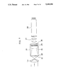
- FIG. 7 is a sectional view of one example of a photodetector employed in the high sensitive multi-wavelength spectral analyzer of the present invention, which comprises a combination of a two-dimensional photon counting tube and a low-visual persistence vidicon;
- FIG. 8 is a sectional view of a photoncounting image acquisition system as another example of the photodetector employed in the present invention.
- FIG. 9 is a sectional view of high sensitive multi-wavelength spectroscopic systems each incorporating the high sensitive multi-wavelength spectral analyzer of the present invention shown in FIG. 1;
- FIG. 10 shows the optical arrangement of one example of the multi-stage, high sensitive, multiplex multi-wavelength spectral analyzer according to the present invention
- FIG. 11 shows the optical arrangement of another example of the multi-stage, high sensitive, multiplex multi-wavelength spectral analyzer according to the present invention.
- FIG. 12 shows the optical arrangement of still another example of the multi-stage, high sensitive, multiplex multi-wavelength spectral analyzer according to the present invention
- FIG. 13 is a conceptual view of a system for spectral analysis of fluorescence or Raman scattered light from a sample of ordinary size
- FIG. 14 is a conceptual view of a microspectroscopic system for fluorescence or Raman scattered light.
- FIG. 15 is a graph showing measured values for the sensitivity performance of the high sensitive multi-wavelength spectral analyzer according to the present invention.
- spectral analysis of extremely weak radiation such as bioluminescence, chemiluminescence, extremely weak fluorescence caused by excitation light, Raman scattered light, etc.
- a spectral line image that is formed by the spectroscopic system must be as rectilinear as possible.
- lenses and reflection converging mirrors are considered to be suitable.
- image formation by a reflection converging mirror is not strictly limited by the wavelength used, so that it can be used over a spectral range of from the ultraviolet region to the infrared region.
- a converging mirror is used as an imaging element, it is necessary to adopt an off-axis optical system arrangement in which light is made incident at an angle to the normal (optical axis) of the converging mirror and the reflected light is taken out at an angle to the normal.
- the off-axis angle becomes large inevitably because it is necessary to avoid interference between the entrance-side converging mirror (collimator mirror) and the diffraction-side converging mirror (imaging mirror). Therefore, if the entrance slit is high, the diffraction image is curved owing to the off-axis aberration and the diffraction by the diffraction grating. In other words, if a reflection converging mirror is used, luminosity and the rectilinearity of the spectral line image (slit image) are incompatible with each other.
- the spectral line image is curved by the off-axis arrangement when a reflection converging mirror is employed as an imaging system, as described above, it is necessary in order to obtain high luminosity and high dispersion to increase the focal length of the converging mirror instead of increasing the angle of incidence and the angle of diffraction.
- the spectroscopic system increases in size, so that, if the number of spectroscopic systems is increased to form a multi-stage spectral analyzer, the overall size increases more and more.
- a lens when employed as an imaging element, it need not be used in an off-axis state, so that the slit image is rectilinear.
- a lens system that comprises a combination of optical glass lenses has the smallest f-number, and no reflecting mirror can match it in the light-gathering capability. More specifically, in the case of a lens, the solid angle for an extremely weak light emission point can be made as large as possible, and a spectral line image that is formed by the spectroscopic system can be made as rectilinear as possible.
- the present invention employs optical lenses having a small f-number as collimator and imaging systems, and a reflection diffraction grating as a spectroscopic system that diffracts parallel rays formed by the optical lens to produce spectra.
- a photon counting type or high sensitivity one- or two-dimensional photodetector that detects electrically a spectral intensity distribution image is disposed on an image plane where a spectral distribution image is formed through the diffraction grating and the imaging system, thereby simultaneously detecting light intensities at various wavelengths.
- FIG. 1 shows a basic form of the high sensitive multi-wavelength spectral analyzer according to the present invention.
- the illustrated apparatus comprises a spectroscope 1 and a high sensitive one- or two-dimensional photodetector 6.
- the spectroscope 1 comprises an entrance slit 2 serving as an optical system that limits a measuring point on a sample S to a point or linear form, a collimator lens 3 with a small f-number which is disposed such that a focal point thereof is coincident with the entrance slit 2, to take in light emerging from the entrance slit 2 as much as possible and convert it into parallel rays, a reflection diffraction grating 4 which diffracts the parallel rays from the collimator lens 3 to produce spectra, and an imaging lens 5 that focuses the parallel rays diffracted by the reflection diffraction grating 4 on an image plane P to form a spectral image.
- the high sensitive one- or two-dimensional photodetector 6 is disposed on the image plane P where the spectral image is formed.
- the reflection diffraction grating 4 is arranged to be rotatable about the center C as shown by the arrows in the figure for adjustment of the detection spectral range.
- d is the grating interval of the reflection diffraction grating 4, i the angle of incidence to the reflection diffraction grating 4, ⁇ the angle of diffraction from the reflection diffraction grating 4, ⁇ the wavelength, and m the order of diffraction.
- a spectral image is formed on the high sensitive one- or two-dimensional photodetector 6.
- analyzing the output from the photodetector 6 to obtain coordinates of each point on the image and an image intensity at the point it is possible to simultaneously measure spectral characteristics of extremely weak radiation from an object that produces bioluminescence, chemiluminescence, extremely weak fluorescence caused by excitation light, etc.
- FIG. 2(a) shows the -first-order grazing incidence spectroscope
- FIG. 2(b) shows the +first-order grazing incidence spectroscope.
- a blazed diffraction grating is employed as the reflection diffraction grating 4, and it is disposed as illustrated.
- FIG. 3 is an optical path diagram for examination of the -first-order grazing incidence spectroscope.
- the optical axis of the imaging lens is coincident with the bisecting angle ⁇ ce of the short wavelength-side diffraction angle ⁇ a and the long wavelength-side diffraction angle ⁇ b .
- D i is the diameter of the collimator lens 3
- l the width of the diffraction grating 4, ⁇ ce the diffraction angle of the center wavelength
- D o the diameter of the imaging lens 5
- L the distance from the center of the reflection diffraction grating 4 to the imaging lens 5.
- the diameter of the imaging lens 5 must be selected so as to satisfy the following condition:
- the +first-order grazing incidence spectroscope shown in FIG. 3(b) is examined in the same way to obtain
- the aperture of the imaging lens 5 must be selected so as to satisfy the following condition:
- the -first-order grazing incidence spectroscope needs to dispose the blazed diffraction grating such that incident light strikes even on short diffraction surfaces, as shown in FIG. 3(a), diffracted light from the short diffraction surfaces becomes stray light, resulting in an increase in the background light.
- the blazed diffraction grating is disposed such that no light is incident on the short diffraction surfaces.
- the diameter of the imaging lens 5 needs to be larger than that of the collimator lens 3, as described above.
- the collimator lens 3 has a small f-number and a diameter which is as large as possible; therefore, it is difficult to employ an imaging lens having a diameter larger than that of the collimator lens 3. Accordingly, if the +first-order grazing incidence spectroscope employs an imaging lens 5 which has a diameter as large as that of the collimator lens 3, the loss is large.
- the -first-order grazing incidence spectroscope is suitable for spectral detection of extremely weak spontaneous emission such as bioluminescence, chemiluminescence, etc.
- extremely weak spontaneous emission such as bioluminescence, chemiluminescence, etc.
- the +first-order grazing incidence spectroscope in which stray light does not conceal the signal light, is more suitable despite some loss of light.
- the +first-order grazing incidence spectroscope is more suitable even for spectral detection of extremely weak spontaneous emission such as bioluminescence, chemiluminescence, etc., as a matter of course.
- the imaging lens 5 and the reflection diffraction grating 4 are disposed with the angle therebetween adjusted so that the center wavelength of diffracted light of proper order comes in the center of the high sensitive one- or two-dimensional photodetector 6, as described above, because the diffracted light emerging from the imaging lens 5 includes beams of light, e.g., -first-order diffracted light, +first-order diffracted light, etc., in addition to the zero-order diffracted light, as shown in FIG. 1.
- the geometrical optical light-receiving efficiency needs to be considered with the multiplex multi-wavelength spectroscope, although it need not be taken into consideration in the case of the conventional wavelength scanning system. More specifically, in the multiplex system, beams of light which are different in diffraction angle are condensed through the imaging lens to observe simultaneously all light in the observation wavelength region. Therefore, when the wavelength at the extremity of the observation wavelength region has a large angle difference with respect to the optical axis of the center wavelength, an eclipse due to the imaging lens 5 occurs, resulting in a lowering in the light-receiving efficiency.
- the distance from the center of the reflection diffraction grating 4 to the imaging lens 5 is shortened.
- the angle at which light from the collimator lens 3 is incident on the reflection diffraction grating 4 needs to be minimized in a range within which the required lens arrangement can be realized.
- the above-mentioned expression for the imaging lens represents the relationship between the minimum necessary aperture D o with respect to light incident on the lens and the distance L to the imaging lens.
- the entrance slit 2 may be replaced with an optical element which can receive light from a sample or from a minute region or a relatively broad region of a sample image and emit light in the form of a point or linear beam.
- an optical concentrator 2b that collects light from the sample S through an entrance window and emits it through a point or linear exit end may be employed as in the case of a high sensitive multi-wavelength spectral analyzer shown in FIG. 4. It is also possible to employ a pinhole.
- the collimator lens 3 and the imaging lens 5 each comprise a single lens
- a standard lens or a telephotographic lens which has a small f-number and comprises a plurality of spherical lenses, as shown exemplarily in FIGS. 5(a) and 5(b).
- aspherical lenses or Fresnel lenses are also possible. The same is the case with embodiments described hereinbelow.
- the spectral analyzer may have a single lens which is designed to serve as both a collimator lens and an imaging lens. More specifically, as shown in FIG. 6(a), a collimator-imaging lens 7 having a small f-number is disposed parallel in front of the reflection diffraction grating 4, and the entrance slit 2 is disposed at a focal point of the lens 7, and further a high sensitive one- or two-dimensional photodetector 6 is disposed at a position where the diffracted light from the reflection diffraction grating 4 forms an image through the lens 7, thereby making light from the sample incident in the normal direction (normal incidence spectroscope).
- the respective positions of the entrance slit 2 and the high sensitive one- or two-dimensional photodetector 6 may be changed for each other so that light from the sample is made incident in an oblique direction (grazing incidence spectroscope), as shown in FIG. 6(b).
- grazing incidence spectroscope a grazing incidence spectroscope
- FIG. 6(b) The grazing incidence spectroscope, shown in FIG. 6(b), is easier in the disposition of the photodetector 6 than the normal incidence spectroscope, shown in FIG. 6(a).
- Examples of the photon counting type or high sensitive one- or two-dimensional photodetector 6 include a system (VIMS) comprising a combination of a two-dimensional photon counting tube and a low-visual persistence vidicon, as shown in FIG. 7, a photoncounting image acquisition system (PIAS) as shown in FIG. 8, a photodetector array comprising photodiodes arranged in the form of an array, a CCD, and a system wherein the light-receiving surface of such a photodetector is cooled to minimize noise so as to obtain high sensitivity.
- VIP system
- PIAS photoncounting image acquisition system
- FIG. 8 a photodetector array comprising photodiodes arranged in the form of an array, a CCD, and a system wherein the light-receiving surface of such a photodetector is cooled to minimize noise so as to obtain high sensitivity.
- photons that are incident on a photoelectric surface 22 of a two-dimensional photon counting tube 21 are converted into photoelectrons, which then pass through a mesh 23 and an electron lens 24 to enter a two-stage microchannel plate (MCP) 25 where the photoelectrons are amplified and then strike on a fluorescent screen 26 as a plane of emergence to form bright dots.
- MCP microchannel plate
- the bright dots are focused to a photoelectric surface of a low-visual persistence vidicon 28 through a lens system 27, thus allowing two-dimensional positions of the bright dots corresponding to the incident photons to be obtained as pulse signals from the output of the vidicon 28. Accordingly, by obtaining a distribution of the bright dots, a spectral distribuation image of extremely weak radiation can be obtained.
- a section that comprises the photoelectric surface 22 to the MCP 25 has the same arrangement as that of the VIMS shown in FIG. 8 (though the MCP 25 in FIG. 8 is a three-stage MCP). Electron groups from the MCP 25 enter a silicon semiconductor position detector (PSD) 29 disposed at the back of the MCP 25, where they are further amplified by the electron bombardment effect and are then output from the PSD 29 in the form of pulse signals.
- PSD 29 is an electric charge distribution type position detector having four signal output electrodes 30 on the periphery thereof, wherein electric charges produced inside the PSD 29 are distributed to the four electrodes 30 through a surface resistance layer in accordance with the positions where they are produced.
- signals corresponding to the barycentric positions of electron groups entering the PSD 29, that is, the bright dot positions, are obtained from the four electrodes 30.
- the pulse signals obtained from the PSD 29 are amplified in respective amplifiers 32 and then led to a position computing unit 31. By integrating these pulse signals in respective integrating circuits 33, an electric charge quantity from each electrode 30 is obtained.
- the resulting signals are led to an adder-subtracter circuit 34 and then led to dividers 36 through a window gate 35, where they are converted to position signals, which are then AD converted in AD converters 37 before being output.
- a bright dot distribution is obtained.
- a spectral distribution image of extremely weak radiation is obtained.
- reference numeral L o denotes an objective lens through which an image of incident photons (shown by the arrow) is formed on the photoelectric surface 12.
- the spectroscope 1 shown in FIG. 1 is disposed such that the entrance slit thereof is at the upper side, and a sample S is disposed in a sample chamber 10 with a temperature controller in such a manner that the sample S is in direct contact with the upper side of the slit, thereby detecting a spectral distribution image of extremely weak radiation from the sample S with the high sensitive one- or two-dimensional photodetector 6.
- Reference numeral 9 in the figure denotes an angle adjusting mechanism for the diffraction grating of the spectroscope 1.
- FIG. 9(b) shows a high sensitive multi-wavelength spectroscopic system in which the sample S is not in direct contact with the spectroscope 1, but it is disposed to face the spectroscope 1 through a condenser lens 11.
- a Fresnel lens is employed as the condenser lens 11, it will be apparent that a normal spherical lens may be employed in place of it.
- the Fresnel lens 11 can be used as a lens that introduces only rectilinearly propagating light from the sample S instead of using it as an imaging lens, so that the quantity of light incident on the spectroscope can be increased, advantageously.
- the condenser lens 11 it is necessary to employ a lens that has an f-number equal to or smaller than that of the collimator lens 3 in the spectroscope 1 so that the converging angle of light from the condenser lens 11 is not smaller than the light acceptance angle of the collimator lens 3.
- the spectroscopic systems shown in FIGS. 9(a) and 9(b) are arranged such that light that is emitted from the sample downwardly is received for spectral analysis, it will be apparent that, when light that is emitted from the sample upwardly or sidewardly is to be subjected to spectral analysis, the spectroscope 1 and the associated elements should be disposed in accordance with the direction of light from the sample.
- spectroscopes are disposed in two or more stages to form an arrangement for additive dispersion to thereby control angular dispersion by using diffracted light a plurality of times, the overall resolving power can be improved.
- Such an arrangement is particularly effective when the wavelength difference between the excitation light and the Raman scattered light is small as in Raman spectroscopy. It is also possible to arrange spectroscopes in two or more stages for subtractive dispersion, as a matter of course.
- FIGS. 10 to 12 Examples of such multi-stage, high sensitive, multiplex multi-wavelength spectral analyzer according to the present invention are shown in FIGS. 10 to 12.
- FIG. 10 shows a multi-stage spectral analyzer wherein four -first-order grazing incidence spectroscopes 1 1 to 1 4 , shown in FIG. 2(a), are arranged in series in the shape of a square as a whole.
- FIG. 11 shows a multi-stage spectral analyzer wherein four +first-order grazing incidence spectroscopes 1 1 to 1 4 , shown in FIG. 2(b), are arranged in series in the shape of a square as a whole.
- FIG. 10 shows a multi-stage spectral analyzer wherein four -first-order grazing incidence spectroscopes 1 1 to 1 4 , shown in FIG. 2(a), are arranged in series in the shape of a square as a whole.
- FIG. 12 shows a multi-stage spectral analyzer wherein three +first-order grazing incidence spectroscopes 1 1 to 1 3 are arranged in series. It should be noted that the number of stages is not necessarily limited to those described above. It is also possible to combine together the -first-order grazing incidence type of spectroscope and the +first-order grazing incidence type of spectroscope.
- FIG. 13 is a conceptual view of a system for spectral analysis of fluorescence or Raman scattered light from a sample S of ordinary size.
- Light from an excitation light source 40 is passed through a spectroscope 41 for excitation to take out excitation light of a desired wavelength, and the sample S is irradiated with the excitation light.
- Fluorescence or Raman scattered light from the sample S is incident on a high sensitive multi-wavelength spectral analyzer 50 employing lenses according to the present invention to effect simultaneous, multi-wavelength spectral analysis.
- a high sensitive multi-wavelength spectral analyzer 50 comprising a single spectroscope suffices in general.
- Raman scattered light since the wavelength difference between excitation light and stray light is small, it is necessary to employ a high sensitive multi-wavelength spectral analyzer 50 comprising spectroscopes arranged in a multi-stage structure, as shown in FIGS. 10 to 12, which provides high wavelength resolution (the same is the case with microspectroscopic analysis shown below).
- a laser is employed as the excitation light source 40, no spectroscope 41 for excitation is needed.
- a microspectroscopic system such as that shown in FIG. 14 is employed, whereby it is possible to realize simultaneous multi-wavelength spectral analysis of high luminosity that utilizes the advantageous features of the high sensitive multi-wavelength spectral analyzer 50 according to the present invention.
- a microspectroscopic system such as that shown in FIG. 14 is employed, whereby it is possible to realize simultaneous multi-wavelength spectral analysis of high luminosity that utilizes the advantageous features of the high sensitive multi-wavelength spectral analyzer 50 according to the present invention.
- the luminosity of the spectroscope determines the sensitivity limit.
- fluorescence or Raman scattered light from a sample S excited by light from an excitation light source L s1 or L s2 is converted to parallel rays through an objective lens 51 having a small f-number and then focused onto the entrance slit 2 of the high sensitive multi-wavelength spectral analyzer 50 of the present invention through a second positive (imaging) lens 52 having the same f-number as that of the objective lens 51.
- the f-number of the collimator lens in the high sensitive multi-wavelength spectral analyzer 50 is equal or as close to the f-number of the objective and imaging lenses 51 and 52 as possible.
- the f-number of the objective and imaging lenses 51 and 52 is larger than that of the collimator lens, part of the light is lost (i.e., if the f-number of the objective lens 51 is excessively large, there will be a loss of the quantity of light taken in from the emission point on the sample S; if the f-number of the imaging lens 52 is excessively large, the image of the emission point on the sample S that is formed on the entrance slit 2 is enlarged excessively, so that the image is partially cut off by the slit 2, resulting in a loss). In such a case, the high luminosity of the high sensitive multi-wavelength spectral analyzer 50 cannot be utilized to the full. In FIG.
- reference numeral 53 denotes a dichroic mirror that directs light from the excitation light source L s2 to the sample S and passes fluorescence or Raman scattered light from the sample S, and 54 a sample scanning mechanism that scans the sample S to change analyzing points successively.
- the light-transmitting characteristics of a lens are limited by the glass medium thereof.
- a high-sensitive spectroscope that is designed mainly for the visible region can use lenses of high luminosity. Since spectral analysis of fluorescence and Raman scattered light is generally carried out in the visible region, the high sensitive multi-wavelength spectral analyzer of the present invention is also considered to be suitable from this point.
- the high sensitive multi-wavelength spectral analyzer of the present invention can also be employed for absorption spectroscopy and reflection spectroscopy in addition to spectral analysis of luminescence, fluorescence and Raman scattered light, as a matter of course.
- the multiplex method has two advantages, that is, observation time and reduction of dark noise.
- observation time is T when multiplex spectroscopy is carried out for a wavelength region W with a detector having a size L and N pixels and with a wavelength resolution R
- observation time for each pixel is T
- observation time per wavelength resolution is also T.
- the observation time per wavelength resolution is T ⁇ R/W because only light of a wavelength width coming out of the exit slit (the resolution is determined by the wavelength width of the exit slit) is observed. Accordingly, from the viewpoint of the observation time, the multiplex method makes it possible to expect W/R-fold improvement over the wavelength scanning method.
- Dark noise is considered to be proportional to the area of the light-receiving surface. Assuming that the two methods use detectors having the same light-receiving surface area, in the case of the multiplex method light of a certain wavelength arrives at a place on the light-receiving surface of the detector that is equivalent to the resolution wavelength width. Accordingly, for dark noise that is equivalent to light of this wavelength, it is only necessary to consider dark noise in a place where light arrives. Assuming that dark noise generated in the whole area of the light-receiving surface of the detector is D, dark noise that is equivalent to the resolution wavelength width is D ⁇ R/W. In contrast, in the wavelength scanning method, D is constant for each wavelength independently of resolution because of use of a single-channel detector.
- the present invention has the advantages of the multiplex method in regard to both the observation time and the reduction of dark noise and enables a great improvement in sensitivity, particularly in the high-resolution region.
- the multiplex method by the high sensitive multi-wavelength spectral analyzer of the present invention makes it possible to expect at least M 1/2 -fold improvement in sensitivity over the wavelength scanning method by the monochromator.
- FIG. 15 shows measured values for the sensitivity performance of a high sensitive multi-wavelength spectral analyzer constructed on a trial basis according to the present invention. Measurement was carried out by using light of 546 nm among the emission lines of mercury with a resolution of 6.5 nm. The entrance slit width was 200 ⁇ m, and the height was 10 mm. A detector comprising a combination of a two-dimensional photon counting tube and a low-visual persistence vidicon, as shown in FIG. 7, was employed. As will be clear from the graph of FIG. 15, the minimum detectable signal was 10 -15 W at a gate time of 10 sec, and 10 -16 W at a gate time of 400 sec. In the prior art, the minimum detectable signal is 10 -12 W at best. From this point, the high sensitivity of the high sensitive multi-wavelength spectral analyzer of the present invention will be understood.
- the high sensitive multi-wavelength spectral analyzer of the present invention has the optical system 2 that limits incident light to a point or linear beam, the collimator lens 3 having a small f-number, the reflection diffraction grating 4, the imaging lens 5 having a small f-number, and the photon counting type or high sensitive one- or two-dimensional photodetector 6, and it realizes the following excellent effects in spectral analysis of extremely weak radiation from the sample S, such as bioluminescence, chemiluminescence, extremely weak fluorescence caused by excitation light, Raman scattered light, etc.
- the optical system 2 which limits incident light to a point or linear beam, causes light from the sample S to enter the collimator lens 3 as a point or linear light source, and the collimator lens 3 converts the light from the sample S into parallel rays of high parallelism and allows all the parallel rays to enter the reflection diffraction grating 4. Accordingly, the reflection diffraction grating 4 can display its resolving power to the full and effectively diffract extremely weak light to produce spectra.
- the collimator lens 3 and the imaging lens 5 can be disposed in close proximity to the reflection diffraction grating 4 and need not be used in an off-axis state, so that all the incident light can be utilized effectively for high resolution, simultaneous, multi-wavelength spectral analysis, and it is possible to realize a reduction in the overall size of the apparatus.
- the most important effect is that since lenses having an f-number as small as possible can be used as the collimator lens 3 and the imaging lens 5, the light-gathering capability of the apparatus, which is determined by the two lenses, can be increased satisfactorily.
- the spectral analyzer of the present invention is useful as a means for researching living organisms and trace components by use of bioluminescence, chemiluminescence, extremely weak fluorescence caused by excitation light, Raman scattered light, etc.
Abstract
Description
sin i+sin β=mλ/d
D.sub.i =l cos i
D.sub.o =l cos β.sub.ce +2LtanΔβ, Δβ=β.sub.a -β.sub.ce
D.sub.i >D.sub.o
D.sub.i =l cos i
D.sub.o =l cos β.sub.ce +2LtanΔβ, Δβ=β.sub.b -β.sub.ce
D.sub.i <D.sub.o
(S/N).sub.m =P.sub.m ·I.sub.m ·T.sup.1/2 /(P.sub.m ·I.sub.m +D.sub.m /M).sup.1/2
(S/N).sub.s =P.sub.s ·I.sub.s ·(T/M).sup.1/2 /(P.sub.s ·I.sub.s +D.sub.s).sup.1/2
Claims (12)
Applications Claiming Priority (2)
| Application Number | Priority Date | Filing Date | Title |
|---|---|---|---|
| JP3-015628 | 1991-02-07 | ||
| JP3015628A JPH05231938A (en) | 1991-02-07 | 1991-02-07 | Highly sensitive multiwavelength spectral apparatus |
Publications (1)
| Publication Number | Publication Date |
|---|---|
| US5329353A true US5329353A (en) | 1994-07-12 |
Family
ID=11893982
Family Applications (1)
| Application Number | Title | Priority Date | Filing Date |
|---|---|---|---|
| US07/832,475 Expired - Lifetime US5329353A (en) | 1991-02-07 | 1992-02-07 | High sensitive multi-wavelength spectral analyzer |
Country Status (4)
| Country | Link |
|---|---|
| US (1) | US5329353A (en) |
| EP (1) | EP0498644B1 (en) |
| JP (1) | JPH05231938A (en) |
| DE (1) | DE69206641T2 (en) |
Cited By (42)
| Publication number | Priority date | Publication date | Assignee | Title |
|---|---|---|---|---|
| US5589717A (en) * | 1993-01-11 | 1996-12-31 | Instruments Sa, Inc. | Compact spectrum analyzer module |
| DE19611218A1 (en) * | 1995-06-20 | 1997-01-02 | Hewlett Packard Co | Optical spectrograph, esp. with low number aperture, for e.g. chemical analysis in industry, medicine or scientific research |
| US5724135A (en) * | 1996-03-27 | 1998-03-03 | The United States Of America As Represented By The Secretary Of The Navy | Hyper-spectral imaging using rotational spectro-tomography |
| US5822222A (en) * | 1995-04-05 | 1998-10-13 | New Jersey Institute Of Technology | Multi-wavelength imaging pyrometer |
| US5880830A (en) * | 1997-01-29 | 1999-03-09 | Greenvision Systems Ltd. | Spectral imaging method for on-line analysis of polycyclic aromatic hydrocarbons in aerosols |
| US5998796A (en) * | 1997-12-22 | 1999-12-07 | Spectrumedix Corporation | Detector having a transmission grating beam splitter for multi-wavelength sample analysis |
| US6016222A (en) * | 1996-11-20 | 2000-01-18 | Canon Kabushiki Kaisha | Color image reading apparatus |
| US6055451A (en) | 1997-12-12 | 2000-04-25 | Spectrx, Inc. | Apparatus and method for determining tissue characteristics |
| US6081332A (en) * | 1997-12-24 | 2000-06-27 | Ando Electric Co., Ltd. | Monochromator |
| WO2001007896A1 (en) * | 1999-07-21 | 2001-02-01 | Tropix, Inc. | Luminescence detection workstation |
| US20020036234A1 (en) * | 2000-03-31 | 2002-03-28 | Hong Tang | Spectral data collector which includes a lambertian reflector |
| US6522402B1 (en) * | 1998-04-30 | 2003-02-18 | California Institute Of Technology | Apparatus and method for analyzing microscopic samples based on optical parametric oscillation |
| DE10137428A1 (en) * | 2001-07-27 | 2003-02-20 | Karlsruhe Forschzent | Device for measuring a solar UV radiation spectrum is configured to allow fast and simultaneous measurement of a spectrum with, at the same time, sufficiently high suppression of scattered light and sufficient dynamic range |
| US6690467B1 (en) | 2000-05-05 | 2004-02-10 | Pe Corporation | Optical system and method for optically analyzing light from a sample |
| US20040061855A1 (en) * | 2000-12-21 | 2004-04-01 | Hansjorg Klock | Optical sensor device and method for spectral analysis |
| US20040088113A1 (en) * | 2002-10-31 | 2004-05-06 | Eastman Kodak Company | Detecting natural gas pipeline failures |
| US20040156048A1 (en) * | 2002-12-31 | 2004-08-12 | Wavefront Research, Inc. | Compact hyperspectral imager |
| US20040160612A1 (en) * | 2001-06-29 | 2004-08-19 | Dieter Grafe | Device and method for local resolution measurement of the thickeness of a layer |
| US20040263852A1 (en) * | 2003-06-03 | 2004-12-30 | Lasen, Inc. | Aerial leak detector |
| US7251026B2 (en) | 2001-03-02 | 2007-07-31 | Waters Investments Limited | Fluorescence detector geometry |
| US20070196049A1 (en) * | 2001-09-10 | 2007-08-23 | Gunn Lawrence C Iii | Tunable resonant cavity based on the field effect in semiconductors |
| US20080085504A1 (en) * | 2006-10-10 | 2008-04-10 | Bryan Bjorndal | System and method for quantifying toxicity in water, soil, and sediments |
| US20080179539A1 (en) * | 2007-01-25 | 2008-07-31 | Amgen Inc. | Apparatus and Method for Interleaving Detection of Fluorescence and Luminescence |
| US20080180663A1 (en) * | 2006-10-19 | 2008-07-31 | Kaiser Optical Systems | Raman probe configured for low-concentration measurements |
| US20100028725A1 (en) * | 2007-05-04 | 2010-02-04 | Zillmer Andrew J | Fuel cell instrumentation system |
| WO2010048073A2 (en) * | 2008-10-20 | 2010-04-29 | Ningbo Yuanlu Electro-Optics, Co., Ltd. | Spectrometers with aberration-corrected concave diffraction gratings and transmissive aberration correctors |
| US20120038918A1 (en) * | 2010-08-13 | 2012-02-16 | Zhiwen Liu | Compact Spectrometer Including a Diffractive Optical Element with Dual Dispersion and Focusing Functionality |
| US8203710B1 (en) | 2006-06-12 | 2012-06-19 | Wavefront Research, Inc. | Compact wide field fast hyperspectral imager |
| US20130148195A1 (en) * | 2010-05-18 | 2013-06-13 | Itres Research Limited | Compact, light-transfer system for use in image relay devices, hyperspectral imagers and spectographs |
| US8477296B2 (en) | 2010-04-12 | 2013-07-02 | University of Maribor | Opto-electronic signal processing methods, systems, and apparatus for optical sensor interrogation |
| US20130169959A1 (en) * | 2011-07-08 | 2013-07-04 | Optopo Inc. d/b/a Centice Corp. | Zero order sensing to increase light collection in a spectrometer |
| RU2492434C1 (en) * | 2012-01-24 | 2013-09-10 | Федеральное государственное бюджетное учреждение науки Институт мониторинга климатических и экологических систем Сибирского отделения Российской академии наук (ИМКЭС СО РАН) | Multi-channel high-performance raman spectrometer |
| US20140016345A1 (en) * | 2011-03-24 | 2014-01-16 | Olympus Corporation | Illumination system |
| US20160069742A1 (en) * | 2012-10-19 | 2016-03-10 | Oto Photonics Inc. | Miniature spectrometer and method of assembling the same |
| CN106052866A (en) * | 2016-05-11 | 2016-10-26 | 中南民族大学 | Biophoton spectrum detection system and method |
| CN108956507A (en) * | 2018-09-20 | 2018-12-07 | 河南农业大学 | Chlorophyll spectrum detection instrument |
| CN110596026A (en) * | 2019-10-12 | 2019-12-20 | 中国科学院合肥物质科学研究院 | Broadband cavity enhancement device |
| CN111965152A (en) * | 2020-08-13 | 2020-11-20 | 公安部物证鉴定中心 | A identification appearance that is used for on-spot biological spot of criminal investigation to detect |
| KR20210067915A (en) * | 2019-11-29 | 2021-06-08 | 주식회사 스킨어세이 | Apertureless sprctrometer |
| CN113790798A (en) * | 2021-09-03 | 2021-12-14 | 中国科学院西安光学精密机械研究所 | Seamless spectral imaging device, system and method for dynamic point target tracking measurement |
| US11307091B2 (en) * | 2019-11-29 | 2022-04-19 | Answeray Inc. | Apertureless spectrometer |
| WO2023051877A1 (en) * | 2021-09-30 | 2023-04-06 | Micro-Epsilon Optronic Gmbh | Spectrometer, distance measuring system, and method for operating a spectrometer |
Families Citing this family (15)
| Publication number | Priority date | Publication date | Assignee | Title |
|---|---|---|---|---|
| US5442439A (en) * | 1993-04-21 | 1995-08-15 | Kaiser Optical Systems, Inc. | Spectrograph with multiplexing of different wavelength regions onto a single opto-electric detector array |
| GB2362460A (en) * | 2000-05-19 | 2001-11-21 | William Howard Considine | Spectroscope |
| JP2001330563A (en) * | 2000-05-23 | 2001-11-30 | Jeol Ltd | Inspection device |
| JP4357421B2 (en) * | 2002-07-12 | 2009-11-04 | リヴァー ダイアグノスティックス ベースローテン フェンノートシャップ | Optical spectrometer |
| JP4883549B2 (en) * | 2004-12-09 | 2012-02-22 | 大学共同利用機関法人自然科学研究機構 | Spectrometer |
| JP5438926B2 (en) * | 2008-07-16 | 2014-03-12 | オリンパス株式会社 | Spectrometer |
| WO2010133485A1 (en) * | 2009-05-16 | 2010-11-25 | Boehringer Ingelheim Microparts Gmbh | Miniaturized confocal spectrometer |
| CN101915755B (en) * | 2010-07-16 | 2011-08-31 | 中国海洋大学 | Underwater Raman-fluorescence spectrum combined detection device |
| EP2533077A1 (en) * | 2011-06-08 | 2012-12-12 | Nederlandse Organisatie voor toegepast -natuurwetenschappelijk onderzoek TNO | Diffraction grating and method for producing same |
| CN104011563B (en) * | 2011-10-24 | 2016-08-17 | 大陆-特韦斯贸易合伙股份公司及两合公司 | Sensing system for its data precision of independent assessment |
| CN103471717B (en) * | 2013-09-17 | 2016-01-20 | 中国科学院长春光学精密机械与物理研究所 | Based on the super-resolution spectrograph of many slit array |
| CN104034419B (en) * | 2014-05-05 | 2017-04-05 | 中国科学院长春光学精密机械与物理研究所 | The imaging spectral instrument system of recoverable Spectral line bend and its bearing calibration |
| CN107389602A (en) * | 2017-08-30 | 2017-11-24 | 无锡迅杰光远科技有限公司 | A kind of spectroscopic system based on DLP technologies |
| CN109580581A (en) * | 2018-12-12 | 2019-04-05 | 哈尔滨工业大学(威海) | A kind of laser Raman spectrometer based on composite grating |
| WO2023228450A1 (en) * | 2022-05-27 | 2023-11-30 | 浜松ホトニクス株式会社 | Spectrometry device |
Citations (4)
| Publication number | Priority date | Publication date | Assignee | Title |
|---|---|---|---|---|
| US3600093A (en) * | 1969-11-10 | 1971-08-17 | Sperry Rand Corp | Continuously blazed optical monochromator |
| US4076421A (en) * | 1976-03-23 | 1978-02-28 | Kollmorgen Technologies Corporation | Spectrophotometer with parallel sensing |
| DE2758141A1 (en) * | 1977-12-27 | 1979-06-28 | Ibm Deutschland | SPECTROPHOTOMETER |
| US4973159A (en) * | 1986-12-01 | 1990-11-27 | Hitachi, Ltd. | Spectroscope apparatus and reaction apparatus using the same |
Family Cites Families (3)
| Publication number | Priority date | Publication date | Assignee | Title |
|---|---|---|---|---|
| DE3403372C1 (en) * | 1984-02-01 | 1985-07-25 | Fraunhofer-Gesellschaft zur Förderung der angewandten Forschung e.V., 8000 München | Multichannel process spectrometer |
| US4895445A (en) * | 1987-06-25 | 1990-01-23 | Eastman Kodak Company | Spectrophotometer |
| EP0343018A3 (en) * | 1988-05-20 | 1990-12-19 | Research Development Corporation Of Japan | Spectroscopes |
-
1991
- 1991-02-07 JP JP3015628A patent/JPH05231938A/en active Pending
-
1992
- 1992-02-06 EP EP92300991A patent/EP0498644B1/en not_active Expired - Lifetime
- 1992-02-06 DE DE69206641T patent/DE69206641T2/en not_active Expired - Fee Related
- 1992-02-07 US US07/832,475 patent/US5329353A/en not_active Expired - Lifetime
Patent Citations (4)
| Publication number | Priority date | Publication date | Assignee | Title |
|---|---|---|---|---|
| US3600093A (en) * | 1969-11-10 | 1971-08-17 | Sperry Rand Corp | Continuously blazed optical monochromator |
| US4076421A (en) * | 1976-03-23 | 1978-02-28 | Kollmorgen Technologies Corporation | Spectrophotometer with parallel sensing |
| DE2758141A1 (en) * | 1977-12-27 | 1979-06-28 | Ibm Deutschland | SPECTROPHOTOMETER |
| US4973159A (en) * | 1986-12-01 | 1990-11-27 | Hitachi, Ltd. | Spectroscope apparatus and reaction apparatus using the same |
Cited By (69)
| Publication number | Priority date | Publication date | Assignee | Title |
|---|---|---|---|---|
| US5589717A (en) * | 1993-01-11 | 1996-12-31 | Instruments Sa, Inc. | Compact spectrum analyzer module |
| US5822222A (en) * | 1995-04-05 | 1998-10-13 | New Jersey Institute Of Technology | Multi-wavelength imaging pyrometer |
| DE19611218A1 (en) * | 1995-06-20 | 1997-01-02 | Hewlett Packard Co | Optical spectrograph, esp. with low number aperture, for e.g. chemical analysis in industry, medicine or scientific research |
| US5644396A (en) * | 1995-06-20 | 1997-07-01 | Hewlett-Packard Company | Spectrograph with low focal ratio |
| US5724135A (en) * | 1996-03-27 | 1998-03-03 | The United States Of America As Represented By The Secretary Of The Navy | Hyper-spectral imaging using rotational spectro-tomography |
| US6016222A (en) * | 1996-11-20 | 2000-01-18 | Canon Kabushiki Kaisha | Color image reading apparatus |
| US5880830A (en) * | 1997-01-29 | 1999-03-09 | Greenvision Systems Ltd. | Spectral imaging method for on-line analysis of polycyclic aromatic hydrocarbons in aerosols |
| US6055451A (en) | 1997-12-12 | 2000-04-25 | Spectrx, Inc. | Apparatus and method for determining tissue characteristics |
| US6118127A (en) * | 1997-12-22 | 2000-09-12 | Spectrumedix Corporation | Detector having a transmission grating beam splitter for multi-wavelength sample analysis |
| US5998796A (en) * | 1997-12-22 | 1999-12-07 | Spectrumedix Corporation | Detector having a transmission grating beam splitter for multi-wavelength sample analysis |
| US6081332A (en) * | 1997-12-24 | 2000-06-27 | Ando Electric Co., Ltd. | Monochromator |
| US6522402B1 (en) * | 1998-04-30 | 2003-02-18 | California Institute Of Technology | Apparatus and method for analyzing microscopic samples based on optical parametric oscillation |
| US20100248387A1 (en) * | 1999-07-21 | 2010-09-30 | Life Technologies Corporation | Method for Measuring Luminescence at a Luminescence Detection Workstation |
| US6518068B1 (en) * | 1999-07-21 | 2003-02-11 | Tropix, Inc. | Luminescence detection workstation |
| US8278114B2 (en) * | 1999-07-21 | 2012-10-02 | Applied Biosystems, Llc | Method for measuring luminescence at a luminescence detection workstation |
| US20030092194A1 (en) * | 1999-07-21 | 2003-05-15 | Gambini Michael R. | Luminescence detection workstation |
| WO2001007896A1 (en) * | 1999-07-21 | 2001-02-01 | Tropix, Inc. | Luminescence detection workstation |
| US20060088444A1 (en) * | 1999-07-21 | 2006-04-27 | Gambini Michael R | Luminescence detection workstation |
| US7670848B2 (en) | 1999-07-21 | 2010-03-02 | Applied Biosystems, Llc | Method for measuring luminescence at a luminescence detection workstation |
| US8865473B2 (en) * | 1999-07-21 | 2014-10-21 | Applied Biosystems, Llc | Luminescence detecting apparatuses and methods |
| US20020036234A1 (en) * | 2000-03-31 | 2002-03-28 | Hong Tang | Spectral data collector which includes a lambertian reflector |
| US6690467B1 (en) | 2000-05-05 | 2004-02-10 | Pe Corporation | Optical system and method for optically analyzing light from a sample |
| US20040061855A1 (en) * | 2000-12-21 | 2004-04-01 | Hansjorg Klock | Optical sensor device and method for spectral analysis |
| US7057723B2 (en) * | 2000-12-21 | 2006-06-06 | De La Rue International Limited | Optical sensor device and method for spectral analysis |
| US7251026B2 (en) | 2001-03-02 | 2007-07-31 | Waters Investments Limited | Fluorescence detector geometry |
| US20040160612A1 (en) * | 2001-06-29 | 2004-08-19 | Dieter Grafe | Device and method for local resolution measurement of the thickeness of a layer |
| DE10137428A1 (en) * | 2001-07-27 | 2003-02-20 | Karlsruhe Forschzent | Device for measuring a solar UV radiation spectrum is configured to allow fast and simultaneous measurement of a spectrum with, at the same time, sufficiently high suppression of scattered light and sufficient dynamic range |
| US20070196049A1 (en) * | 2001-09-10 | 2007-08-23 | Gunn Lawrence C Iii | Tunable resonant cavity based on the field effect in semiconductors |
| US7027924B2 (en) * | 2002-10-31 | 2006-04-11 | Itt Manufacturing Enterprises, Inc | Detecting natural gas pipeline failures |
| US20040088113A1 (en) * | 2002-10-31 | 2004-05-06 | Eastman Kodak Company | Detecting natural gas pipeline failures |
| US7199876B2 (en) * | 2002-12-31 | 2007-04-03 | Wavefront Research, Inc. | Compact hyperspectral imager |
| US20040156048A1 (en) * | 2002-12-31 | 2004-08-12 | Wavefront Research, Inc. | Compact hyperspectral imager |
| US20040263852A1 (en) * | 2003-06-03 | 2004-12-30 | Lasen, Inc. | Aerial leak detector |
| US9086317B1 (en) | 2006-06-12 | 2015-07-21 | Wavefront Research, Inc. | Compact wide field fast hyperspectral imager |
| US9964443B1 (en) | 2006-06-12 | 2018-05-08 | Wavefront Research, Inc. | Contact wide field fast hyperspectral imager |
| US8203710B1 (en) | 2006-06-12 | 2012-06-19 | Wavefront Research, Inc. | Compact wide field fast hyperspectral imager |
| US20080085504A1 (en) * | 2006-10-10 | 2008-04-10 | Bryan Bjorndal | System and method for quantifying toxicity in water, soil, and sediments |
| US7704731B2 (en) | 2006-10-10 | 2010-04-27 | The United States Of America As Represented By The Secretary Of The Navy | System and method for quantifying toxicity in water, soil, and sediments |
| US7692786B2 (en) | 2006-10-19 | 2010-04-06 | Kaiser Optical Systems | Raman probe configured for low-concentration measurements |
| US20080180663A1 (en) * | 2006-10-19 | 2008-07-31 | Kaiser Optical Systems | Raman probe configured for low-concentration measurements |
| US20080179539A1 (en) * | 2007-01-25 | 2008-07-31 | Amgen Inc. | Apparatus and Method for Interleaving Detection of Fluorescence and Luminescence |
| US7700928B2 (en) | 2007-01-25 | 2010-04-20 | Etaluma, Inc. | Apparatus and method for interleaving detection of fluorescence and luminescence |
| US20100193705A1 (en) * | 2007-01-25 | 2010-08-05 | Brian Rasnow | Apparatus and method for interleaving detection of fluorescence and luminescence |
| US20100028725A1 (en) * | 2007-05-04 | 2010-02-04 | Zillmer Andrew J | Fuel cell instrumentation system |
| US7826054B2 (en) * | 2007-05-04 | 2010-11-02 | Pratt & Whitney Rocketdyne, Inc. | Fuel cell instrumentation system |
| WO2010048073A3 (en) * | 2008-10-20 | 2010-07-22 | Ningbo Yuanlu Electro-Optics, Co., Ltd. | Spectrometers with aberration-corrected concave diffraction gratings and transmissive aberration correctors |
| CN102165337A (en) * | 2008-10-20 | 2011-08-24 | 宁波源禄光电有限公司 | Spectrometers with aberration-corrected concave diffraction gratings and transmissive aberration correctors |
| WO2010048073A2 (en) * | 2008-10-20 | 2010-04-29 | Ningbo Yuanlu Electro-Optics, Co., Ltd. | Spectrometers with aberration-corrected concave diffraction gratings and transmissive aberration correctors |
| US8477296B2 (en) | 2010-04-12 | 2013-07-02 | University of Maribor | Opto-electronic signal processing methods, systems, and apparatus for optical sensor interrogation |
| US20130148195A1 (en) * | 2010-05-18 | 2013-06-13 | Itres Research Limited | Compact, light-transfer system for use in image relay devices, hyperspectral imagers and spectographs |
| US20120038918A1 (en) * | 2010-08-13 | 2012-02-16 | Zhiwen Liu | Compact Spectrometer Including a Diffractive Optical Element with Dual Dispersion and Focusing Functionality |
| US8861086B2 (en) * | 2010-08-13 | 2014-10-14 | The Penn State Research Foundation | Compact spectrometer including a diffractive optical element with dual dispersion and focusing functionality |
| US10041655B2 (en) | 2011-03-24 | 2018-08-07 | Olympus Corporation | Illumination system |
| US9261261B2 (en) * | 2011-03-24 | 2016-02-16 | Olympus Corporation | Illumination system |
| US20140016345A1 (en) * | 2011-03-24 | 2014-01-16 | Olympus Corporation | Illumination system |
| US20130169959A1 (en) * | 2011-07-08 | 2013-07-04 | Optopo Inc. d/b/a Centice Corp. | Zero order sensing to increase light collection in a spectrometer |
| RU2492434C1 (en) * | 2012-01-24 | 2013-09-10 | Федеральное государственное бюджетное учреждение науки Институт мониторинга климатических и экологических систем Сибирского отделения Российской академии наук (ИМКЭС СО РАН) | Multi-channel high-performance raman spectrometer |
| US20160069742A1 (en) * | 2012-10-19 | 2016-03-10 | Oto Photonics Inc. | Miniature spectrometer and method of assembling the same |
| US10215633B2 (en) * | 2012-10-19 | 2019-02-26 | Oto Photonics Inc. | Miniature spectrometer and method of assembling the samens |
| CN106052866A (en) * | 2016-05-11 | 2016-10-26 | 中南民族大学 | Biophoton spectrum detection system and method |
| CN108956507B (en) * | 2018-09-20 | 2024-03-01 | 河南农业大学 | Chlorophyll spectrum detector |
| CN108956507A (en) * | 2018-09-20 | 2018-12-07 | 河南农业大学 | Chlorophyll spectrum detection instrument |
| CN110596026A (en) * | 2019-10-12 | 2019-12-20 | 中国科学院合肥物质科学研究院 | Broadband cavity enhancement device |
| KR20210067915A (en) * | 2019-11-29 | 2021-06-08 | 주식회사 스킨어세이 | Apertureless sprctrometer |
| US11307091B2 (en) * | 2019-11-29 | 2022-04-19 | Answeray Inc. | Apertureless spectrometer |
| CN111965152A (en) * | 2020-08-13 | 2020-11-20 | 公安部物证鉴定中心 | A identification appearance that is used for on-spot biological spot of criminal investigation to detect |
| CN113790798A (en) * | 2021-09-03 | 2021-12-14 | 中国科学院西安光学精密机械研究所 | Seamless spectral imaging device, system and method for dynamic point target tracking measurement |
| CN113790798B (en) * | 2021-09-03 | 2022-07-19 | 中国科学院西安光学精密机械研究所 | Seamless spectral imaging device, system and method for dynamic point target tracking measurement |
| WO2023051877A1 (en) * | 2021-09-30 | 2023-04-06 | Micro-Epsilon Optronic Gmbh | Spectrometer, distance measuring system, and method for operating a spectrometer |
Also Published As
| Publication number | Publication date |
|---|---|
| EP0498644A1 (en) | 1992-08-12 |
| EP0498644B1 (en) | 1995-12-13 |
| JPH05231938A (en) | 1993-09-07 |
| DE69206641T2 (en) | 1996-05-02 |
| DE69206641D1 (en) | 1996-01-25 |
Similar Documents
| Publication | Publication Date | Title |
|---|---|---|
| US5329353A (en) | High sensitive multi-wavelength spectral analyzer | |
| US5166755A (en) | Spectrometer apparatus | |
| US5515169A (en) | Spectral wavelength discrimination system and method for using | |
| US5495334A (en) | Fourier transform spectroscope with quadrangular common path interferometer | |
| US20120262713A1 (en) | Spectrometer arrangement | |
| JPS628729B2 (en) | ||
| KR100316847B1 (en) | High-resolution, compact intracavity laser spectrometer | |
| US6208413B1 (en) | Hadamard spectrometer | |
| JPWO2003016842A1 (en) | Spectroscopic device and spectroscopic method | |
| US5050989A (en) | Single Hadamard mask spectrograph system | |
| US20020018203A1 (en) | Spectrophotometer system having active pixel array | |
| US6813019B2 (en) | Method and apparatus for spectrochemical analysis | |
| US7321423B2 (en) | Real-time goniospectrophotometer | |
| US5721613A (en) | Fluorescence spectrometer | |
| Barbillat et al. | Multi‐channel micro‐Raman spectroscopy with near‐infrared excitation. II | |
| JPH07280732A (en) | Fluorescence spectrometer | |
| JP3226308B2 (en) | Bright high-resolution spectrometer | |
| JP2749387B2 (en) | High-sensitivity micro-multi-wavelength spectrometer | |
| JPH071206B2 (en) | High sensitivity multi-wavelength spectrometer | |
| JPH10227693A (en) | Spectrometer | |
| JP3134262B2 (en) | Square common path interferometer Fourier transform spectrometer | |
| Bormett et al. | 2-D Light Diffraction from CCD and Intensified Reticon Multichannel Detectors Causes Spectrometer Stray Light Problems | |
| JPH05203492A (en) | Raman spectrophotometer | |
| JP2000074742A (en) | Spectroscope and light spectrum analyzer | |
| JP2667526B2 (en) | High sensitivity multi-wavelength emission fluorescence spectroscopy method and apparatus |
Legal Events
| Date | Code | Title | Description |
|---|---|---|---|
| AS | Assignment |
Owner name: NAGOSHI, TOSHIYUKI, JAPAN Free format text: ASSIGNMENT OF ASSIGNORS INTEREST.;ASSIGNORS:ICHIMURA, TSUTOMU;NAGOSHI, TOSHIYUKI;INABA, FUMIO;REEL/FRAME:006020/0914 Effective date: 19920129 Owner name: RESEARCH DEVELOPMENT CORPORATION OF JAPAN, JAPAN Free format text: ASSIGNMENT OF ASSIGNORS INTEREST.;ASSIGNORS:ICHIMURA, TSUTOMU;NAGOSHI, TOSHIYUKI;INABA, FUMIO;REEL/FRAME:006020/0914 Effective date: 19920129 Owner name: ICHIMURA, TSUTOMU, JAPAN Free format text: ASSIGNMENT OF ASSIGNORS INTEREST.;ASSIGNORS:ICHIMURA, TSUTOMU;NAGOSHI, TOSHIYUKI;INABA, FUMIO;REEL/FRAME:006020/0914 Effective date: 19920129 |
|
| STCF | Information on status: patent grant |
Free format text: PATENTED CASE |
|
| FPAY | Fee payment |
Year of fee payment: 4 |
|
| FPAY | Fee payment |
Year of fee payment: 8 |
|
| AS | Assignment |
Owner name: JAPAN SCIENCE AND TECHNOLOGY CORPORATION, JAPAN Free format text: ASSIGNMENT OF ASSIGNORS INTEREST;ASSIGNORS:ICHIMURA, TSUTOMU;NAGOSHI, TOSHIYUKI;REEL/FRAME:012865/0293 Effective date: 20011105 |
|
| FEPP | Fee payment procedure |
Free format text: PAYOR NUMBER ASSIGNED (ORIGINAL EVENT CODE: ASPN); ENTITY STATUS OF PATENT OWNER: LARGE ENTITY |
|
| FPAY | Fee payment |
Year of fee payment: 12 |