US5321434A - Digital color printer with improved lateral registration - Google Patents
Digital color printer with improved lateral registration Download PDFInfo
- Publication number
- US5321434A US5321434A US07/991,228 US99122892A US5321434A US 5321434 A US5321434 A US 5321434A US 99122892 A US99122892 A US 99122892A US 5321434 A US5321434 A US 5321434A
- Authority
- US
- United States
- Prior art keywords
- belt
- ros
- lateral
- image
- signals
- Prior art date
- Legal status (The legal status is an assumption and is not a legal conclusion. Google has not performed a legal analysis and makes no representation as to the accuracy of the status listed.)
- Expired - Fee Related
Links
- 238000000034 method Methods 0.000 claims abstract description 24
- 230000008569 process Effects 0.000 claims description 16
- 108091008695 photoreceptors Proteins 0.000 claims description 15
- 230000004044 response Effects 0.000 claims description 6
- 238000003384 imaging method Methods 0.000 claims description 5
- 230000007246 mechanism Effects 0.000 claims description 5
- 230000015572 biosynthetic process Effects 0.000 claims description 3
- 230000005540 biological transmission Effects 0.000 claims 1
- 238000012937 correction Methods 0.000 abstract description 8
- 238000012545 processing Methods 0.000 description 6
- 238000011161 development Methods 0.000 description 3
- 239000003086 colorant Substances 0.000 description 2
- 239000002131 composite material Substances 0.000 description 2
- 230000003287 optical effect Effects 0.000 description 2
- 238000012546 transfer Methods 0.000 description 2
- 230000008859 change Effects 0.000 description 1
- 230000000052 comparative effect Effects 0.000 description 1
- 238000001514 detection method Methods 0.000 description 1
- 230000023077 detection of light stimulus Effects 0.000 description 1
- 239000000463 material Substances 0.000 description 1
- 238000012986 modification Methods 0.000 description 1
- 230000004048 modification Effects 0.000 description 1
- 238000012544 monitoring process Methods 0.000 description 1
- 230000005855 radiation Effects 0.000 description 1
- 238000000926 separation method Methods 0.000 description 1
- 238000011144 upstream manufacturing Methods 0.000 description 1
Images


Classifications
-
- G—PHYSICS
- G06—COMPUTING; CALCULATING OR COUNTING
- G06K—GRAPHICAL DATA READING; PRESENTATION OF DATA; RECORD CARRIERS; HANDLING RECORD CARRIERS
- G06K15/00—Arrangements for producing a permanent visual presentation of the output data, e.g. computer output printers
- G06K15/02—Arrangements for producing a permanent visual presentation of the output data, e.g. computer output printers using printers
- G06K15/12—Arrangements for producing a permanent visual presentation of the output data, e.g. computer output printers using printers by photographic printing, e.g. by laser printers
- G06K15/129—Colour printing
-
- B—PERFORMING OPERATIONS; TRANSPORTING
- B41—PRINTING; LINING MACHINES; TYPEWRITERS; STAMPS
- B41J—TYPEWRITERS; SELECTIVE PRINTING MECHANISMS, i.e. MECHANISMS PRINTING OTHERWISE THAN FROM A FORME; CORRECTION OF TYPOGRAPHICAL ERRORS
- B41J2/00—Typewriters or selective printing mechanisms characterised by the printing or marking process for which they are designed
- B41J2/435—Typewriters or selective printing mechanisms characterised by the printing or marking process for which they are designed characterised by selective application of radiation to a printing material or impression-transfer material
- B41J2/47—Typewriters or selective printing mechanisms characterised by the printing or marking process for which they are designed characterised by selective application of radiation to a printing material or impression-transfer material using the combination of scanning and modulation of light
- B41J2/471—Typewriters or selective printing mechanisms characterised by the printing or marking process for which they are designed characterised by selective application of radiation to a printing material or impression-transfer material using the combination of scanning and modulation of light using dot sequential main scanning by means of a light deflector, e.g. a rotating polygonal mirror
- B41J2/473—Typewriters or selective printing mechanisms characterised by the printing or marking process for which they are designed characterised by selective application of radiation to a printing material or impression-transfer material using the combination of scanning and modulation of light using dot sequential main scanning by means of a light deflector, e.g. a rotating polygonal mirror using multiple light beams, wavelengths or colours
-
- G—PHYSICS
- G06—COMPUTING; CALCULATING OR COUNTING
- G06K—GRAPHICAL DATA READING; PRESENTATION OF DATA; RECORD CARRIERS; HANDLING RECORD CARRIERS
- G06K15/00—Arrangements for producing a permanent visual presentation of the output data, e.g. computer output printers
- G06K15/02—Arrangements for producing a permanent visual presentation of the output data, e.g. computer output printers using printers
- G06K15/12—Arrangements for producing a permanent visual presentation of the output data, e.g. computer output printers using printers by photographic printing, e.g. by laser printers
- G06K15/1204—Arrangements for producing a permanent visual presentation of the output data, e.g. computer output printers using printers by photographic printing, e.g. by laser printers involving the fast moving of an optical beam in the main scanning direction
- G06K15/1219—Detection, control or error compensation of scanning velocity or position, e.g. synchronisation
-
- G—PHYSICS
- G03—PHOTOGRAPHY; CINEMATOGRAPHY; ANALOGOUS TECHNIQUES USING WAVES OTHER THAN OPTICAL WAVES; ELECTROGRAPHY; HOLOGRAPHY
- G03G—ELECTROGRAPHY; ELECTROPHOTOGRAPHY; MAGNETOGRAPHY
- G03G2215/00—Apparatus for electrophotographic processes
- G03G2215/00135—Handling of parts of the apparatus
- G03G2215/00139—Belt
- G03G2215/00143—Meandering prevention
-
- G—PHYSICS
- G03—PHOTOGRAPHY; CINEMATOGRAPHY; ANALOGOUS TECHNIQUES USING WAVES OTHER THAN OPTICAL WAVES; ELECTROGRAPHY; HOLOGRAPHY
- G03G—ELECTROGRAPHY; ELECTROPHOTOGRAPHY; MAGNETOGRAPHY
- G03G2215/00—Apparatus for electrophotographic processes
- G03G2215/01—Apparatus for electrophotographic processes for producing multicoloured copies
- G03G2215/0167—Apparatus for electrophotographic processes for producing multicoloured copies single electrographic recording member
- G03G2215/017—Apparatus for electrophotographic processes for producing multicoloured copies single electrographic recording member single rotation of recording member to produce multicoloured copy
Definitions
- a ROS incorporates a laser for generating a collimated beam of monochromatic radiation.
- the laser beam is modulated in conformance with the image information.
- the modulated beam is incident on a scanning element, typically a rotating polygon having mirrored facets.
- the light beam is reflected from each facet and thereafter focused to a spot on the photosensitive member.
- the rotation of the polygon causes the spot to scan linearly across the photoconductive member in a fast scan (i.e., line scan) direction.
- Color digital printers may operate in either a single pass or multiple pass mode.
- three ROS imagers are positioned adjacent to a moving photoreceptor surface and are selectively energized to create successive image exposures, one for each of the three process colors, cyan, magenta and yellow.
- a fourth black imager is usually added.
- a color digital printer may also operate in a highlight color mode wherein one or two colors and black are exposed.
- each image area on the photoreceptor surface must make at least three revolutions (passes) relative to the transverse scan lines formed by the modulated beam generated by the imagers.
- each image is typically formed within a tight tolerance of ⁇ 0.05 mm.
- Each color image must be registered in both the photoreceptor process direction and in the direction perpendicular to the process direction (referred to as fast scan, lateral or transverse registration). The description "lateral" will be used hereafter.
- U.S. Pat. No. 4,912,491 to Hoshino discloses an apparatus for forming superimposed images as well as forming registration marks corresponding to the position of the images associated therewith.
- the registration marks are formed apart from the imaging portion of the medium and are formed in a transparent area so as to be illuminable from below.
- detectors detect the position of the registration marks as the marks pass between the illuminated areas. The detection/sensing of marked positions is used in determining proper registration positioning whereby the image forming devices may be adjusted to achieve such registration.
- U.S. Pat. No. Re. 32,967 to St. John et al. a reissue of U.S. Pat. No. 4,485,982, issued Dec. 4, 1984, discloses a web tracking system for a continuous web which passes along a predetermined path through one or more processing stations.
- the tracking system has aligned tracking indicia on one or both sides of the web and means are provided for sensing these indicia which are indicative of dimensional changes in width and length of the web at a particular point and further there is also provided an edge sensor to determine movement of the web itself.
- U.S. Pat. No. 4,961,089 to Jamzadeh discloses an electrostatic reproduction apparatus having a web tracking system wherein the web rotates about image processing stations with a plurality of rollers.
- a guide means is provided to move the web around the rollers.
- the guide means include a steering roller which is actuated according to a web tracking system.
- This invention provides a means and method to compensate for lateral registration errors in color digital printers adapted to form a composite color image.
- the invention comprises a plurality of ROS image processing stations for forming composite images on a photosensitive belt surface movable relative to the image processing stations.
- Monitoring means are provided for determining a lateral deviation of the belt and to compute the lateral deviation of the surface at each of the image processing stations.
- the invention also includes means for compensating for the lateral deviations of the belt at each of the image processing stations.
- the present invention is used in a digital color printer which incorporates of a plurality of Raster Output Scanner (ROS) imagers in a single pass mode or incorporates a single ROS imager in a multiple pass mode.
- a split cell photodetector comprising two photosites with a common junction, is positioned at each ROS station at the beginning of the scan line formed by the imager and beneath the surface of the moving photoreceptor belt.
- a ROS scan beam is periodically swept across the surface of the belt in a fast scan (lateral) direction.
- a belt aperture formed in the surface of the belt in a non-image area is periodically in alignment with this detector as the belt is moved in the process direction.
- the belt hole moves across the scan line being laid down by the ROS imager.
- the ROS scan line is, therefore, viewed by the split cell detector through the aperture.
- the detector operation generates two separate electrical signals separated by a time delay, due to the space between the photodiode sites.
- An electrical circuit generates a signal when the two signals cross. Lateral movement of the belt from station to station creates signals of differing magnitude; the difference is used to generate correction signals to the individual ROS imager to adjust the first image pixel of the image scan line being formed.
- the present invention relates to a digital color printer for forming multiple color image exposure frames on a photoconductive member including:
- Raster Output Scanner (ROS) imager which generates successive scan lines across the photoreceptor surface to produce said exposure frames in response to input video signals
- split cell detecting means associated with each said ROS imager for detecting changes in the lateral position of said belt, said detecting means generating output signals when said ROS scan lines are visible through said aperture of said belt as said belt moves in the process direction, and
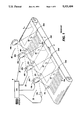
- FIG. 1 shows a prior art color printer with a plurality of Raster Output Scanners (ROSs) used as the color imagers.
- ROSs Raster Output Scanners
- FIG. 2 shows the printer of FIG. 1 modified by adding an aperture through the belt and a split cell photodetector beneath the belt, opposite each ROS imager, according to the invention.
- FIG. 3 shows a portion of the photoreceptor belt with an aperture therethrough advancing in a process direction towards a split cell photodetector.
- FIG. 4 shows the signal outputs from the photodetector shown in FIG. 2.
- FIG. 5A shows several possible locations of the belt hole with respect to the photodetector.
- FIG. 5B shows the photodetector output signals for each belt hole location of FIG. 5A.
- FIG. 6 shows circuitry for generating lateral correction signals from the photodetectors and use of the signals to correct for lateral misregistration.
- each of the image exposure frames I 1 -I 4 reaches a transverse line of scan, represented by lines 19, 29, 39, 49, the frame is progressively exposed on closely spaced transverse raster lines, shown generally with exaggerated longitudinal spacing as reference numerals 19a and 49a on the image areas I 1 and I 4 , respectively.
- a development station Downstream from each exposure station, a development station (not shown) develops the latent image formed in the associated image area. A fully developed color image is then transferred to an output sheet at a transfer station (not shown).
- the charge, development, and transfer stations are conventional in the art. Details of charge and development xerographic stations in a multiple exposure single pass system are disclosed, for example, in U.S. Pat. Nos. 4,833,503; 4,611,901 and 4,791,452, the contents of which are hereby incorporated by reference.
- Each ROS system 10, 20, 30, and 40 contains its own conventional scanning components, as variously described in the art.
- each ROS system 10, 20, 30, 40 is shown as having two components, namely, a laser light source 10a, 20a, 30a, 40a and a rotating polygon 10b, 20b, 30b, 40b, respectively. It will be appreciated by those of skill in the art that multiple scan lines may also be generated with a single ROS in a multiple pass system.
- An exemplary ROS system 10 includes a gas, or preferably, diode laser light source 10a, having an output which is modulated by signals from control circuit 8, which output is optically processed to impinge on the facets of rotating polygon 10b. Each facet reflects the modulated incident laser beam as it is rotated to produce a scan line which is focused at the photoreceptor surface 2.
- Electronic Sub System (ESS) 8 contains the circuit and logic modules which respond to input video data signals and other control and timing signals to operate the photoreceptor drive in synchronism with the image exposure and to control the rotation of the polygon 10b by a motor (not shown).
- the other ROS systems 20, 30, 40 have their own associated laser diodes 20a, 30a, 40a, and polygons 20b, 30b, 40b, respectively.
- ROS station 10 has a start-of-scan (SOS) sensor 10c and an end of sensor (EOS) 10d, which are positioned above the surface of belt 2 at the ends of the path of the scanning beam. These sensors generate a pulse each time a scan line is swept across the photoreceptor surface, thereby establishing a start and end of scan for the image content for that particular line.
- SOS start-of-scan
- EOS end of sensor
- Each ROS 20, 30, 40 has an associated detector pair.
- the ROS system must be color-registered so that each image I 1 -I N is registered in both the fast scan (lateral) direction and in the process direction.
- Prior art solutions disclosed formation of holes in the belt outside the image area, location of photosensors beneath each image station and detection of light passage through the belt holes as it advances in the process direction.
- the light was provided, either from a dedicated light source as described in co-pending applications Ser. Nos. 07/635,835 and 07/859,746, filed on Mar. 30, 1992 or the light detected was from the ROS scanning beam, as disclosed, for example, in co-pending application Ser. No. 07/807,927.
- the system of FIG. 1 has been modified by adding belt hole 50 in a non-image area of the belt.
- Each ROS system, 10, 20, 30, 40 has a split cell photodetector 10e, 20e, 30e, 40e, respectively.
- the photodetectors are fixed in place beneath the surface of belt 2 and are aligned in the process direction so as to view the passage of hole 50, as the belt moves the hole therepast.
- the hole has a width in the lateral direction smaller than the width of the photodetector sites.
- FIG. 3 shows a top view of a portion of belt 2 with ROS beam 19 being swept across the surface of the belt. With each beam sweep, the beam is detected at the start of scan by SOS sensor 10c, generating a start of scan signal.
- the first image scan line 19 begins to write the image beginning with pixel 19a, after a previously set time delay. As the belt advances in the process direction (direction of arrow 4), belt hole 50 will cross the scan line and become visible at the split cell photodetector 10e.
- FIG. 3 shows a top view of a portion of belt 2 with ROS beam 19 being swept across the surface of the belt. With each beam sweep, the beam is detected at the start of scan by SOS sensor 10c, generating a start of scan signal.
- the first image scan line 19 begins to write the image beginning with pixel 19a, after a previously set time delay.
- belt hole 50 will cross the scan line and become visible at the split cell photodetector 10e.
- FIG. 4 shows photodetector 10e having two photosites S1, S2, separated by a small space, represented by a boundary line B.
- a boundary line B As beam 19 scans across sites S1, S2, two separate electrical signals V1, V2 are generated separately by a time delay due to the space B between the two sites.
- the time delay between the generation of the signal and the signals from the sensors 10c 10d are measured and the location of the center of the split cell photodetector, relative to the SOS and EOS sensors, is calculated and stored in system memory.
- the third belt hole position indicates the belt has moved laterally to the right; site S2 is receiving light for a longer duration of time and, therefore, V2 is longer in duration than V1.
- FIG. 6 shows circuitry to detect the lateral registration error and generate correction signals. The circuit is shown as operating for the output of split cell detector 10e, but outputs from the other split cell photodetectors would be operated on in a similar fashion. As shown, the signals coming from sites S1, S2 of the detector, are sent to an amplifier 60.
- the output signals V1, V2 will be proportional to the amount of time the beam was present on the photodetector sites.
- the two exposure values are integrated in integrator 65 and then compared in difference amplifier 70.
- the output signal will have a magnitude indicative of the sense and amount of deviation of the belt hole to the sensor.
- a correction signal is sent to either the ESS 8 to delay the beginning of the first pixel location of the image frame, or to a belt steering mechanism 90 to move the belt in an appropriate direction for correction.
- V1 equals V2
- no signal is generated.
Abstract
Description
Claims (5)
Priority Applications (1)
| Application Number | Priority Date | Filing Date | Title |
|---|---|---|---|
| US07/991,228 US5321434A (en) | 1992-12-16 | 1992-12-16 | Digital color printer with improved lateral registration |
Applications Claiming Priority (1)
| Application Number | Priority Date | Filing Date | Title |
|---|---|---|---|
| US07/991,228 US5321434A (en) | 1992-12-16 | 1992-12-16 | Digital color printer with improved lateral registration |
Related Child Applications (1)
| Application Number | Title | Priority Date | Filing Date |
|---|---|---|---|
| US08/269,111 Division US5446089A (en) | 1992-12-15 | 1994-06-30 | Resorcinol-glutaraldehyde resin as an accelerator for curing phenol-formaldehyde resins |
Publications (1)
| Publication Number | Publication Date |
|---|---|
| US5321434A true US5321434A (en) | 1994-06-14 |
Family
ID=25537002
Family Applications (1)
| Application Number | Title | Priority Date | Filing Date |
|---|---|---|---|
| US07/991,228 Expired - Fee Related US5321434A (en) | 1992-12-16 | 1992-12-16 | Digital color printer with improved lateral registration |
Country Status (1)
| Country | Link |
|---|---|
| US (1) | US5321434A (en) |
Cited By (10)
| Publication number | Priority date | Publication date | Assignee | Title |
|---|---|---|---|---|
| US5760914A (en) * | 1996-06-25 | 1998-06-02 | Varis Corporation | Image registration method |
| KR19990045339A (en) * | 1997-11-17 | 1999-06-25 | 윤종용 | Photosensitive belt of printing press, optical scanning system employing the same, and its scanning synchronous data calculation method |
| US6166749A (en) * | 1998-12-07 | 2000-12-26 | Samsung Electronics Co., Ltd. | Optical scanning system for printer |
| US20030147101A1 (en) * | 2002-02-06 | 2003-08-07 | Quad/Tech, Inc. | Camera assembly for a printing press |
| US6644773B2 (en) | 2002-03-15 | 2003-11-11 | International Business Machines Corporation | Method, system, and article of manufacture for performing registration calibration for printing devices |
| US6757071B1 (en) | 1999-11-09 | 2004-06-29 | Xerox Corporation | Intelligent printer driver and user interface and method to recommend and/or automatically modify a document for printing, and a method therefore |
| US7013803B2 (en) | 2002-02-06 | 2006-03-21 | Quad/Tech, Inc. | Color registration control system for a printing press |
| DE102007048864A1 (en) * | 2007-10-11 | 2009-04-16 | Eastman Kodak Co. | Transport arrangement for transporting sheet i.e. print substrate sheet, in e.g. digital printing machine, has drive providing circulating drive for conveyor belt, and sensor detecting change in thickness in region of belt |
| US10774739B2 (en) * | 2018-01-22 | 2020-09-15 | Ford Motor Company | Method and system for detecting misalignment of a front end accessory drive belt |
| JP2020201440A (en) * | 2019-06-12 | 2020-12-17 | シャープ株式会社 | Optical scanner and multi-functional printer |
Citations (7)
| Publication number | Priority date | Publication date | Assignee | Title |
|---|---|---|---|---|
| US4310757A (en) * | 1978-07-07 | 1982-01-12 | Pitney Bowes Inc. | Apparatus for correcting scanning speed in a polygon used for laser scanning |
| US4485982A (en) * | 1982-11-24 | 1984-12-04 | Xerox Corporation | Web tracking system |
| US4611190A (en) * | 1985-03-06 | 1986-09-09 | Control Concepts Corporation | Apparatus for transforming multiphase power of different phase to phase line levels into multiphase power having a single phase to phase voltage level |
| US4791452A (en) * | 1986-10-28 | 1988-12-13 | Kabushiki Kaisha Toshiba | Image forming apparatus having at least two-color image print function and method for controlling the same |
| US4833503A (en) * | 1987-12-28 | 1989-05-23 | Xerox Corporation | Electronic color printing system with sonic toner release development |
| US4912491A (en) * | 1987-05-30 | 1990-03-27 | Canon Kabushiki Kaisha | Apparatus for forming superimposed images |
| US4961089A (en) * | 1988-12-27 | 1990-10-02 | Eastman Kodak Company | Method and apparatus for web tracking with predictive control |
-
1992
- 1992-12-16 US US07/991,228 patent/US5321434A/en not_active Expired - Fee Related
Patent Citations (7)
| Publication number | Priority date | Publication date | Assignee | Title |
|---|---|---|---|---|
| US4310757A (en) * | 1978-07-07 | 1982-01-12 | Pitney Bowes Inc. | Apparatus for correcting scanning speed in a polygon used for laser scanning |
| US4485982A (en) * | 1982-11-24 | 1984-12-04 | Xerox Corporation | Web tracking system |
| US4611190A (en) * | 1985-03-06 | 1986-09-09 | Control Concepts Corporation | Apparatus for transforming multiphase power of different phase to phase line levels into multiphase power having a single phase to phase voltage level |
| US4791452A (en) * | 1986-10-28 | 1988-12-13 | Kabushiki Kaisha Toshiba | Image forming apparatus having at least two-color image print function and method for controlling the same |
| US4912491A (en) * | 1987-05-30 | 1990-03-27 | Canon Kabushiki Kaisha | Apparatus for forming superimposed images |
| US4833503A (en) * | 1987-12-28 | 1989-05-23 | Xerox Corporation | Electronic color printing system with sonic toner release development |
| US4961089A (en) * | 1988-12-27 | 1990-10-02 | Eastman Kodak Company | Method and apparatus for web tracking with predictive control |
Cited By (13)
| Publication number | Priority date | Publication date | Assignee | Title |
|---|---|---|---|---|
| US5760914A (en) * | 1996-06-25 | 1998-06-02 | Varis Corporation | Image registration method |
| US6310695B1 (en) * | 1996-06-25 | 2001-10-30 | Varis Corporation | Image registration method |
| KR19990045339A (en) * | 1997-11-17 | 1999-06-25 | 윤종용 | Photosensitive belt of printing press, optical scanning system employing the same, and its scanning synchronous data calculation method |
| US6166749A (en) * | 1998-12-07 | 2000-12-26 | Samsung Electronics Co., Ltd. | Optical scanning system for printer |
| US6757071B1 (en) | 1999-11-09 | 2004-06-29 | Xerox Corporation | Intelligent printer driver and user interface and method to recommend and/or automatically modify a document for printing, and a method therefore |
| US20030147101A1 (en) * | 2002-02-06 | 2003-08-07 | Quad/Tech, Inc. | Camera assembly for a printing press |
| US7013803B2 (en) | 2002-02-06 | 2006-03-21 | Quad/Tech, Inc. | Color registration control system for a printing press |
| US7253929B2 (en) | 2002-02-06 | 2007-08-07 | Quad/Tech, Inc. | Camera assembly for a printing press |
| US6644773B2 (en) | 2002-03-15 | 2003-11-11 | International Business Machines Corporation | Method, system, and article of manufacture for performing registration calibration for printing devices |
| DE102007048864A1 (en) * | 2007-10-11 | 2009-04-16 | Eastman Kodak Co. | Transport arrangement for transporting sheet i.e. print substrate sheet, in e.g. digital printing machine, has drive providing circulating drive for conveyor belt, and sensor detecting change in thickness in region of belt |
| DE102007048864B4 (en) * | 2007-10-11 | 2011-07-21 | Eastman Kodak Co., N.Y. | Transport arrangement for transporting sheets in a printing machine |
| US10774739B2 (en) * | 2018-01-22 | 2020-09-15 | Ford Motor Company | Method and system for detecting misalignment of a front end accessory drive belt |
| JP2020201440A (en) * | 2019-06-12 | 2020-12-17 | シャープ株式会社 | Optical scanner and multi-functional printer |
Similar Documents
| Publication | Publication Date | Title |
|---|---|---|
| EP0617547B1 (en) | Improved mark detection circuit for an electrographic printing machine | |
| US5260725A (en) | Method and apparatus for registration of sequential images in a single pass, color xerographic printer | |
| US5093674A (en) | Method and system for compensating for paper shrinkage and misalignment in electrophotographic color printing | |
| US7216952B2 (en) | Multicolor-printer and method of printing images | |
| EP0998128B1 (en) | Printer and method of correcting color registration error thereof | |
| US5381165A (en) | Raster output scanner with process direction registration | |
| US5537190A (en) | Method and apparatus to improve registration in a black first printing machine | |
| US5302973A (en) | Method and apparatus for image registration in a single pass ROS system | |
| EP0585022B1 (en) | Method and apparatus for lateral registration of sequential images in a single pass, multi-led print bar printer | |
| US5418556A (en) | Method and apparatus for registering multiple images in a color xerographic system | |
| EP0598566A1 (en) | Method and apparatus for color registration control | |
| US5300961A (en) | Method and apparatus for aligning multiple print bars in a single pass system | |
| JPH10198110A (en) | Color image forming method | |
| EP0596641B1 (en) | Method and apparatus for image registration | |
| JP3449573B2 (en) | Apparatus for recording images on electrostatographic systems | |
| US5319537A (en) | Raser output scanner color printer with improved start of scan detection and process registration | |
| US5321434A (en) | Digital color printer with improved lateral registration | |
| US5229787A (en) | Color printer | |
| EP0816943B1 (en) | Image registration system and method | |
| US6603574B1 (en) | Image color registration sensor calibration | |
| US5412409A (en) | Image registration for a raster output scanner (ROS) color printer | |
| US6323955B1 (en) | Image forming apparatus | |
| JPH0423265B2 (en) | ||
| US5654951A (en) | Dynamic switching speed control | |
| US20030151775A1 (en) | Method and system for tracking a photoconductor belt loop in an image forming apparatus |
Legal Events
| Date | Code | Title | Description |
|---|---|---|---|
| AS | Assignment |
Owner name: XEROX CORPORATION, CONNECTICUT Free format text: ASSIGNMENT OF ASSIGNORS INTEREST;ASSIGNORS:STRAUCH, ANDREW M.;HUBBLE, FRED F., III;OSSMAN, KENNETH R.;REEL/FRAME:006838/0456 Effective date: 19921202 |
|
| FPAY | Fee payment |
Year of fee payment: 4 |
|
| FPAY | Fee payment |
Year of fee payment: 8 |
|
| AS | Assignment |
Owner name: BANK ONE, NA, AS ADMINISTRATIVE AGENT, ILLINOIS Free format text: SECURITY INTEREST;ASSIGNOR:XEROX CORPORATION;REEL/FRAME:013153/0001 Effective date: 20020621 |
|
| AS | Assignment |
Owner name: JPMORGAN CHASE BANK, AS COLLATERAL AGENT, TEXAS Free format text: SECURITY AGREEMENT;ASSIGNOR:XEROX CORPORATION;REEL/FRAME:015134/0476 Effective date: 20030625 Owner name: JPMORGAN CHASE BANK, AS COLLATERAL AGENT,TEXAS Free format text: SECURITY AGREEMENT;ASSIGNOR:XEROX CORPORATION;REEL/FRAME:015134/0476 Effective date: 20030625 |
|
| REMI | Maintenance fee reminder mailed | ||
| LAPS | Lapse for failure to pay maintenance fees | ||
| STCH | Information on status: patent discontinuation |
Free format text: PATENT EXPIRED DUE TO NONPAYMENT OF MAINTENANCE FEES UNDER 37 CFR 1.362 |
|
| FP | Lapsed due to failure to pay maintenance fee |
Effective date: 20060614 |
|
| AS | Assignment |
Owner name: XEROX CORPORATION, CONNECTICUT Free format text: RELEASE BY SECURED PARTY;ASSIGNOR:JPMORGAN CHASE BANK, N.A. AS SUCCESSOR-IN-INTEREST ADMINISTRATIVE AGENT AND COLLATERAL AGENT TO JPMORGAN CHASE BANK;REEL/FRAME:066728/0193 Effective date: 20220822 |