US5318362A - Non-contact techniques for measuring temperature of radiation-heated objects - Google Patents
Non-contact techniques for measuring temperature of radiation-heated objects Download PDFInfo
- Publication number
- US5318362A US5318362A US07/943,927 US94392792A US5318362A US 5318362 A US5318362 A US 5318362A US 94392792 A US94392792 A US 94392792A US 5318362 A US5318362 A US 5318362A
- Authority
- US
- United States
- Prior art keywords
- radiation
- object surface
- level
- light
- heating
- Prior art date
- Legal status (The legal status is an assumption and is not a legal conclusion. Google has not performed a legal analysis and makes no representation as to the accuracy of the status listed.)
- Expired - Lifetime
Links
- 238000000034 method Methods 0.000 title claims abstract description 46
- 230000005855 radiation Effects 0.000 claims abstract description 74
- 238000010438 heat treatment Methods 0.000 claims abstract description 36
- 230000003287 optical effect Effects 0.000 claims abstract description 22
- 230000005670 electromagnetic radiation Effects 0.000 claims abstract description 16
- 239000004065 semiconductor Substances 0.000 claims description 8
- 229910052594 sapphire Inorganic materials 0.000 claims description 6
- 239000010980 sapphire Substances 0.000 claims description 6
- 239000010987 cubic zirconia Substances 0.000 claims description 4
- 239000000463 material Substances 0.000 claims description 4
- 238000005259 measurement Methods 0.000 abstract description 13
- 235000012431 wafers Nutrition 0.000 description 18
- 238000012545 processing Methods 0.000 description 10
- 238000012544 monitoring process Methods 0.000 description 6
- XUIMIQQOPSSXEZ-UHFFFAOYSA-N Silicon Chemical compound [Si] XUIMIQQOPSSXEZ-UHFFFAOYSA-N 0.000 description 4
- 230000000694 effects Effects 0.000 description 4
- 239000013307 optical fiber Substances 0.000 description 4
- 239000010453 quartz Substances 0.000 description 4
- 229910052710 silicon Inorganic materials 0.000 description 4
- 239000010703 silicon Substances 0.000 description 4
- VYPSYNLAJGMNEJ-UHFFFAOYSA-N silicon dioxide Inorganic materials O=[Si]=O VYPSYNLAJGMNEJ-UHFFFAOYSA-N 0.000 description 4
- 230000001419 dependent effect Effects 0.000 description 3
- 230000035945 sensitivity Effects 0.000 description 3
- 230000002596 correlated effect Effects 0.000 description 2
- 239000007789 gas Substances 0.000 description 2
- 238000012986 modification Methods 0.000 description 2
- 230000004048 modification Effects 0.000 description 2
- 238000001228 spectrum Methods 0.000 description 2
- 238000010521 absorption reaction Methods 0.000 description 1
- 238000009529 body temperature measurement Methods 0.000 description 1
- 238000011109 contamination Methods 0.000 description 1
- 238000000295 emission spectrum Methods 0.000 description 1
- 238000003780 insertion Methods 0.000 description 1
- 230000037431 insertion Effects 0.000 description 1
- 238000000691 measurement method Methods 0.000 description 1
- 238000013021 overheating Methods 0.000 description 1
- 238000002310 reflectometry Methods 0.000 description 1
- 229910001220 stainless steel Inorganic materials 0.000 description 1
- 239000010935 stainless steel Substances 0.000 description 1
- 238000012360 testing method Methods 0.000 description 1
- 239000012780 transparent material Substances 0.000 description 1
Images


Classifications
-
- G—PHYSICS
- G01—MEASURING; TESTING
- G01J—MEASUREMENT OF INTENSITY, VELOCITY, SPECTRAL CONTENT, POLARISATION, PHASE OR PULSE CHARACTERISTICS OF INFRARED, VISIBLE OR ULTRAVIOLET LIGHT; COLORIMETRY; RADIATION PYROMETRY
- G01J5/00—Radiation pyrometry, e.g. infrared or optical thermometry
- G01J5/60—Radiation pyrometry, e.g. infrared or optical thermometry using determination of colour temperature
- G01J5/602—Radiation pyrometry, e.g. infrared or optical thermometry using determination of colour temperature using selective, monochromatic or bandpass filtering
-
- G—PHYSICS
- G01—MEASURING; TESTING
- G01J—MEASUREMENT OF INTENSITY, VELOCITY, SPECTRAL CONTENT, POLARISATION, PHASE OR PULSE CHARACTERISTICS OF INFRARED, VISIBLE OR ULTRAVIOLET LIGHT; COLORIMETRY; RADIATION PYROMETRY
- G01J5/00—Radiation pyrometry, e.g. infrared or optical thermometry
- G01J5/0003—Radiation pyrometry, e.g. infrared or optical thermometry for sensing the radiant heat transfer of samples, e.g. emittance meter
- G01J5/0007—Radiation pyrometry, e.g. infrared or optical thermometry for sensing the radiant heat transfer of samples, e.g. emittance meter of wafers or semiconductor substrates, e.g. using Rapid Thermal Processing
-
- G—PHYSICS
- G01—MEASURING; TESTING
- G01J—MEASUREMENT OF INTENSITY, VELOCITY, SPECTRAL CONTENT, POLARISATION, PHASE OR PULSE CHARACTERISTICS OF INFRARED, VISIBLE OR ULTRAVIOLET LIGHT; COLORIMETRY; RADIATION PYROMETRY
- G01J5/00—Radiation pyrometry, e.g. infrared or optical thermometry
- G01J5/02—Constructional details
- G01J5/06—Arrangements for eliminating effects of disturbing radiation; Arrangements for compensating changes in sensitivity
- G01J5/064—Ambient temperature sensor; Housing temperature sensor; Constructional details thereof
-
- G—PHYSICS
- G01—MEASURING; TESTING
- G01J—MEASUREMENT OF INTENSITY, VELOCITY, SPECTRAL CONTENT, POLARISATION, PHASE OR PULSE CHARACTERISTICS OF INFRARED, VISIBLE OR ULTRAVIOLET LIGHT; COLORIMETRY; RADIATION PYROMETRY
- G01J5/00—Radiation pyrometry, e.g. infrared or optical thermometry
- G01J5/02—Constructional details
- G01J5/08—Optical arrangements
- G01J5/0803—Arrangements for time-dependent attenuation of radiation signals
- G01J5/0804—Shutters
-
- G—PHYSICS
- G01—MEASURING; TESTING
- G01J—MEASUREMENT OF INTENSITY, VELOCITY, SPECTRAL CONTENT, POLARISATION, PHASE OR PULSE CHARACTERISTICS OF INFRARED, VISIBLE OR ULTRAVIOLET LIGHT; COLORIMETRY; RADIATION PYROMETRY
- G01J5/00—Radiation pyrometry, e.g. infrared or optical thermometry
- G01J5/02—Constructional details
- G01J5/08—Optical arrangements
- G01J5/0818—Waveguides
-
- G—PHYSICS
- G01—MEASURING; TESTING
- G01J—MEASUREMENT OF INTENSITY, VELOCITY, SPECTRAL CONTENT, POLARISATION, PHASE OR PULSE CHARACTERISTICS OF INFRARED, VISIBLE OR ULTRAVIOLET LIGHT; COLORIMETRY; RADIATION PYROMETRY
- G01J5/00—Radiation pyrometry, e.g. infrared or optical thermometry
- G01J5/02—Constructional details
- G01J5/026—Control of working procedures of a pyrometer, other than calibration; Bandwidth calculation; Gain control
Definitions
- This invention is related generally to temperature and emissivity measurement, and more specifically, to the measurement by pyrometric techniques of high processing temperatures of objects heated by electromagnetic radiation within the visible, infrared or other near-visible wavelength range.
- optical heating techniques There are many examples of the application of optical heating techniques.
- One example is in heating materials for the purpose of testing them.
- Another is in the heat treatment of an object.
- a further example of is found in the semiconductor processing industry.
- silicon wafers to be processed are positioned within an enclosed chamber made, at least partially, of an optically transparent material. Lamps outside the chamber direct a large amount of energy through its transparent walls and onto the wafer.
- the wafer is heated as a result of its absorption of the optical radiation.
- the chamber is formed of a quartz envelope, or of stainless steel with an optical window.
- the heated wafer is treated by introducing appropriate gases into the chamber which react with the heated surface of the wafer.
- thermocouple a conventional thermocouple
- contact measurement techniques most often are precluded because of a number of practical considerations.
- the technique also often results in substantial errors because of a differing thermal mass, poor thermal contact and a difference in emittance between the thermocouple and the object being heated.
- the present invention which allows measurement of object temperature and/or emissivity by monitoring its radiation emission at short wavelengths, even if in a bandwidth that is coincident with that of the strong optical radiation source that is heating the object. According to one aspect of the present invention, this is accomplished by positioning a mirror between the lamps and the object that reflects back toward the lamps a narrow wavelength band, thereby eliminating this band of light from the chamber. A lightpipe then collects only the object's emission light within this reflected band.
- the optical radiation of the alternating current driven heating lamps is monitored simultaneously with monitoring the light from the object in order to develop a measured value proportional to the light being reflected by the object, thereby allowing the object-reflected light to be subtracted from the total signal.
- the optical radiation of the alternating current driven heating lamps is monitored simultaneously with monitoring the light from the object in order to develop a measured value proportional to the light being reflected by the object, thereby allowing the object-reflected light to be subtracted from the total signal.
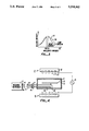
- FIG. 1 illustrates one embodiment of the present invention according to a first aspect
- FIGS. 2 and 3 each show curves of operation of the embodiment of FIG. 1;
- FIG. 4 illustrates one embodiment of the present invention according to a second aspect
- FIG. 5 are curves which show the operation of the embodiment of FIG. 4.
- FIG. 6 shows a modification of the embodiment of FIGS. 4.
- FIG. 1 such a semiconductor wafer 11 is schematically shown to be enclosed within a quartz furnace or processing chamber 13.
- Mechanical supports for the wafer 11 also referred to herein as "object"
- sources of processing gases into a chamber 15 in which the wafer 11 is positioned and other equipment required for processing are omitted for simplicity.
- the wafer 11 is heated by banks 17 and 19 of lamps positioned, in one example, on opposite sides of the wafer 11.
- Each bank of lights includes a reflector 21 and plurality of quartz lamps 23, for example, in the light bank 17.
- a portion of its temperature-dependent emission is gathered by a bent lightpipe 25 that is able to withstand the temperatures within and near the quartz enclosure 13.
- the lightpipe 25 is connected by a coupler 27 to a suitable optical fiber 29.
- the optical fiber 29 carries the emission signal to a measuring instrument 31, where it is detected, electronically processed, and correlated with temperature.
- the method is the same except for the specific geometry.
- Others have generally tended to measure the emission of the object 11 in an optical wavelength band that is outside of the emission band of the lamps 23, in order to avoid the effect of strong optical lamp noise. But the techniques of the present invention allow the measurement to take place in a wavelength band that is near the wavelength of the peak intensity of the lamp 23 and take advantage of the wavelength regions which have high sensitivity and good emissivity for pyrometric measurements.
- FIG. 1 allows this overlapping operation by the provision of highly tuned mirrors 33 and 35 positioned in front of each of the light banks 17 and 19, respectively. These mirrors are chosen to have a narrow, sharp reflection bandwidth centered around the photo-detector's wavelength sensitivity.
- a specific example of a "notch" in the lamp emission wavelengths caused by the mirrors is indicated by a curve 37 of FIG. 3.
- the emission wavelengths of the lamps are indicated by a curve 39.
- a silicon detector within the measuring instrument 31 is provided to monitor the emission from the object 11 at a very narrow wavelength around 0.95 microns.
- the mirrors 33 and 35 are each provided to reflect light from the lamps within a bandwidth, in this example, that is ⁇ 10 nanometers from the 0.95 micron center wavelength. Light within that bandwidth is not allowed to enter the chamber 15 from the lamps. By reflecting the light in this narrow band, rather than absorbing it, overheating of the mirrors 33 and 35 is avoided.
- the structure of each of these mirrors is preferably a multi-layered, mirror of a type used with high powered lasers.
- an advantage of the present invention is illustrated by some example emissivity curves for pure silicon, similar to that of the semiconductor wafers 11 that are radiantly heated.
- the curves of FIG. 2 show an emissivity that varies significantly as a function of temperature in wavelengths longer than one micron. Measurements within this range are difficult to make because of the varying emissivity as a function of the object's temperature. Even so, others using pyrometric techniques for optically heated objects operate within a band around 4, 5 or more microns in order to avoid any overlap with the heating lamp spectra. However, this source of error is eliminated by the techniques of the present invention wherein the capability is provided for measuring temperature by monitoring the object's emission in a wavelength band shorter than one micron.
- the lightpipe 25 is made of sapphire. Because of its refractive index, a sapphire lightpipe 25 has large numerical aperture (angle of acceptance) of radiation from the surface of the heated object 11. In addition to its good optical characteristics, sapphire is able to withstand the high temperatures within the chamber 15. Cubic zirconia also has these desirable characteristics.
- the measuring instrument 31 is preferably a commercially available model 100 of the Accufiber division of Luxtron Corporation, Beaverton, Oregon.
- FIG. 4 A second embodiment of the present invention is illustrated in FIG. 4. Structural elements of FIG. 4 that correspond to those of the embodiment of FIG. 1 are given the same reference number but with a prime (') added.
- An electrical power supply 41 is also indicated for driving the heating lamps of each of the light banks 17' and 19'. These lamps are driven with an alternating current at the power distribution line frequency, 60 Hz., for the United States, and 50 Hz. in Europe.
- FIG. 4 provides no mirrors or optical filters between the light banks and the object 11' being heated. Therefore, the lightpipe 25' will receive a signal that is composed of both reflected lamp light and object emitted light.
- the lamp output is measured without contribution of emission from the object 11' and a signal develops which is then subtracted from the signal from the lightpipe 25' in order to eliminate the effect of the source reflectance from that signal.
- a second lightpipe 43 is provided within the chamber 15' but faces downward toward the lamps of the light bank 19'.
- the optical signal in the lightpipe 43 is connected by a coupler 45 to a standard optical fiber 47.
- the light signals within the optical fibers 29' and 47 are detected by the same type of detectors within a measuring instrument 31', namely respective photodetectors 44 and 46.
- the electrical signal outputs of these detectors are then processed in a way to subtract the effect of the heating lamps out of the signal gathered by the lightpipe 25'.
- a single lightpipe and detector can be provided where the lightpipe is rotated between positions facing the object and the lamps.
- a curve 51 shows the signal level output of the detector receiving the optical signal of the lamps alone through the lightpipe 43.
- An a.c. component of the signal 51 results from an output of the banks 17' and 19' of lamps being modulated by the alternating current supply 41 driving them.
- a curve 53 illustrates the output of the detector receiving the combined object emission and heating light source reflection received by the lightpipe 25'.
- the a.c. component (ripple) of the signal 51 is indicated by ⁇ I L
- the a.c. component of the signal 53 is denoted by ⁇ I W .
- the curves of FIG. 5 also show a steady state signal 55 that is proportional to the emission of the object 11' (E W ), which can be derived by processing within the instrument 31 of the signals 51 and 53.
- Equation (2) provides a measurement of the emissivity of the object. If its temperature is to be measured, the reflected component of I W can then be subtracted away, leaving the object emission signal alone, as follows: ##EQU3## Thus, the quantity E W is solely the object emission and thus can be converted into temperature of the object 11'. E W is determined from processing of the d.c. level and a.c. level of the signals 51 and 53.
- FIGS. 4 and 5 operates well by itself, but can be modified to include insertion in front of the lamp bank 17' and 19' mirrors of the type described for mirrors 33 and 35 of FIG. 1. Such a configuration combines the advantages of both specific embodiments.
- FIG. 6 a modification of the FIG. 4 embodiment is shown.
- the lightpipes 25" and 43' are positioned outside of the enclosure 13".
Abstract
Description
Claims (31)
Priority Applications (4)
| Application Number | Priority Date | Filing Date | Title |
|---|---|---|---|
| US07/943,927 US5318362A (en) | 1990-04-10 | 1992-09-11 | Non-contact techniques for measuring temperature of radiation-heated objects |
| US07/999,278 US5310260A (en) | 1990-04-10 | 1992-12-28 | Non-contact optical techniques for measuring surface conditions |
| US08/180,641 US5490728A (en) | 1990-04-10 | 1994-01-12 | Non-contact optical techniques for measuring surface conditions |
| US08/180,852 US5769540A (en) | 1990-04-10 | 1994-01-12 | Non-contact optical techniques for measuring surface conditions |
Applications Claiming Priority (2)
| Application Number | Priority Date | Filing Date | Title |
|---|---|---|---|
| US07/507,605 US5154512A (en) | 1990-04-10 | 1990-04-10 | Non-contact techniques for measuring temperature or radiation-heated objects |
| US07/943,927 US5318362A (en) | 1990-04-10 | 1992-09-11 | Non-contact techniques for measuring temperature of radiation-heated objects |
Related Parent Applications (3)
| Application Number | Title | Priority Date | Filing Date |
|---|---|---|---|
| US07/507,605 Continuation-In-Part US5154512A (en) | 1990-04-10 | 1990-04-10 | Non-contact techniques for measuring temperature or radiation-heated objects |
| US07/507,605 Continuation US5154512A (en) | 1990-04-10 | 1990-04-10 | Non-contact techniques for measuring temperature or radiation-heated objects |
| US06/692,578 Continuation-In-Part US5166080A (en) | 1990-04-10 | 1991-04-29 | Techniques for measuring the thickness of a film formed on a substrate |
Related Child Applications (1)
| Application Number | Title | Priority Date | Filing Date |
|---|---|---|---|
| US07/999,278 Continuation-In-Part US5310260A (en) | 1990-04-10 | 1992-12-28 | Non-contact optical techniques for measuring surface conditions |
Publications (1)
| Publication Number | Publication Date |
|---|---|
| US5318362A true US5318362A (en) | 1994-06-07 |
Family
ID=24019328
Family Applications (2)
| Application Number | Title | Priority Date | Filing Date |
|---|---|---|---|
| US07/507,605 Expired - Lifetime US5154512A (en) | 1990-04-10 | 1990-04-10 | Non-contact techniques for measuring temperature or radiation-heated objects |
| US07/943,927 Expired - Lifetime US5318362A (en) | 1990-04-10 | 1992-09-11 | Non-contact techniques for measuring temperature of radiation-heated objects |
Family Applications Before (1)
| Application Number | Title | Priority Date | Filing Date |
|---|---|---|---|
| US07/507,605 Expired - Lifetime US5154512A (en) | 1990-04-10 | 1990-04-10 | Non-contact techniques for measuring temperature or radiation-heated objects |
Country Status (2)
| Country | Link |
|---|---|
| US (2) | US5154512A (en) |
| JP (1) | JP3192161B2 (en) |
Cited By (23)
| Publication number | Priority date | Publication date | Assignee | Title |
|---|---|---|---|---|
| US5490728A (en) * | 1990-04-10 | 1996-02-13 | Luxtron Corporation | Non-contact optical techniques for measuring surface conditions |
| US5624590A (en) * | 1993-04-02 | 1997-04-29 | Lucent Technologies, Inc. | Semiconductor processing technique, including pyrometric measurement of radiantly heated bodies and an apparatus for practicing this technique |
| US5755510A (en) * | 1994-10-21 | 1998-05-26 | Societe Europeenne De Propulsionm | Fast bichromatic pyrometer for use with an optical fiber |
| US5769540A (en) * | 1990-04-10 | 1998-06-23 | Luxtron Corporation | Non-contact optical techniques for measuring surface conditions |
| US5861609A (en) * | 1995-10-02 | 1999-01-19 | Kaltenbrunner; Guenter | Method and apparatus for rapid thermal processing |
| US6002113A (en) * | 1998-05-18 | 1999-12-14 | Lucent Technologies Inc. | Apparatus for processing silicon devices with improved temperature control |
| US6044203A (en) * | 1996-07-26 | 2000-03-28 | Advanced Micro Devices, Inc. | Rapid thermal anneal system and method including improved temperature sensing and monitoring |
| US6074087A (en) * | 1997-09-04 | 2000-06-13 | National Security Council | Non-contact method for measuring the surface temperature distribution of a melt during growth of ionic crystals |
| US6183127B1 (en) | 1999-03-29 | 2001-02-06 | Eaton Corporation | System and method for the real time determination of the in situ emissivity of a workpiece during processing |
| US6299346B1 (en) | 1999-03-08 | 2001-10-09 | C. I. Systems Ltd | Active pyrometry with emissivity extrapolation and compensation |
| US6461036B1 (en) | 1999-03-29 | 2002-10-08 | Axcelis Technologies, Inc. | System and method for determining stray light in a thermal processing system |
| US6610968B1 (en) | 2000-09-27 | 2003-08-26 | Axcelis Technologies | System and method for controlling movement of a workpiece in a thermal processing system |
| US20060118983A1 (en) * | 2004-12-03 | 2006-06-08 | Cochran Don W | Method and system for wavelength specific thermal irradiation and treatment |
| US20070096352A1 (en) * | 2004-12-03 | 2007-05-03 | Cochran Don W | Method and system for laser-based, wavelength specific infrared irradiation treatment |
| US20070171958A1 (en) * | 2006-01-23 | 2007-07-26 | Anh Hoang | Electrical device measurement probes |
| DE102006019807B3 (en) * | 2006-04-21 | 2007-08-23 | Leibnitz-Institut für Festkörper- und Werkstoffforschung Dresden e.V. | Pyrometric measurement of temperature or temperature distribution of a melt in crystal growth plants, comprises heating the melt area by infrared radiation sources and interrupting the effect of the radiation sources on the melt area |
| US20090214690A1 (en) * | 2004-11-22 | 2009-08-27 | Sidel Participations | Method and installation for the production of containers |
| US20100089906A1 (en) * | 2007-03-02 | 2010-04-15 | Sidel Participations | heating plastics via infrared radiation |
| DE102011116243A1 (en) | 2011-10-17 | 2013-04-18 | Centrotherm Thermal Solutions Gmbh & Co. Kg | Device for determining the temperature of a substrate |
| WO2013135394A1 (en) | 2012-03-16 | 2013-09-19 | Centrotherm Thermal Solutions Gmbh & Co. Kg | Device for determining the temperature of a substrate |
| US8662876B2 (en) | 2007-06-11 | 2014-03-04 | Sidel Participations | Installation for heating the bodies of preforms for blow-moulding containers |
| WO2014198912A1 (en) | 2013-06-13 | 2014-12-18 | Centrotherm Photovoltaics Ag | Measurement object, method for the production thereof and device for the thermal treatment of substrates |
| WO2016014174A1 (en) * | 2014-07-25 | 2016-01-28 | Applied Materials, Inc. | Light pipe arrays for thermal chamber applications and thermal processes |
Families Citing this family (74)
| Publication number | Priority date | Publication date | Assignee | Title |
|---|---|---|---|---|
| US5154512A (en) * | 1990-04-10 | 1992-10-13 | Luxtron Corporation | Non-contact techniques for measuring temperature or radiation-heated objects |
| US5326173A (en) * | 1993-01-11 | 1994-07-05 | Alcan International Limited | Apparatus and method for remote temperature measurement |
| US5308161A (en) * | 1993-02-11 | 1994-05-03 | Quantum Logic Corporation | Pyrometer apparatus for use in rapid thermal processing of semiconductor wafers |
| US5305416A (en) * | 1993-04-02 | 1994-04-19 | At&T Bell Laboratories | Semiconductor processing technique, including pyrometric measurement of radiantly heated bodies |
| US5891352A (en) * | 1993-09-16 | 1999-04-06 | Luxtron Corporation | Optical techniques of measuring endpoint during the processing of material layers in an optically hostile environment |
| US5650082A (en) * | 1993-10-29 | 1997-07-22 | Applied Materials, Inc. | Profiled substrate heating |
| DE4414391C2 (en) * | 1994-04-26 | 2001-02-01 | Steag Rtp Systems Gmbh | Method for wave vector selective pyrometry in rapid heating systems |
| US5717608A (en) * | 1994-09-26 | 1998-02-10 | Luxtron Corporation | Electro-optical board assembly for measuring the temperature of an object surface from infra-red emissions thereof, including an automatic gain control therefore |
| US5738440A (en) * | 1994-12-23 | 1998-04-14 | International Business Machines Corp. | Combined emissivity and radiance measurement for the determination of the temperature of a radiant object |
| US5683538A (en) * | 1994-12-23 | 1997-11-04 | International Business Machines Corporation | Control of etch selectivity |
| US5830277A (en) * | 1995-05-26 | 1998-11-03 | Mattson Technology, Inc. | Thermal processing system with supplemental resistive heater and shielded optical pyrometry |
| US6002109A (en) * | 1995-07-10 | 1999-12-14 | Mattson Technology, Inc. | System and method for thermal processing of a semiconductor substrate |
| US5938335A (en) * | 1996-04-08 | 1999-08-17 | Applied Materials, Inc. | Self-calibrating temperature probe |
| US5802099A (en) * | 1996-08-26 | 1998-09-01 | Moore Epitaxial, Inc. | Method for measuring substrate temperature in radiant heated reactors |
| US5874711A (en) * | 1997-04-17 | 1999-02-23 | Ag Associates | Apparatus and method for determining the temperature of a radiating surface |
| US5960158A (en) | 1997-07-11 | 1999-09-28 | Ag Associates | Apparatus and method for filtering light in a thermal processing chamber |
| US6027244A (en) * | 1997-07-24 | 2000-02-22 | Steag Rtp Systems, Inc. | Apparatus for determining the temperature of a semi-transparent radiating body |
| US5988874A (en) * | 1997-09-05 | 1999-11-23 | Advanced Micro Devices, Inc. | Black body reference for RTA |
| EP0924500B1 (en) * | 1997-12-08 | 2006-10-18 | STEAG RTP Systems GmbH | Method for the measurement of electromagnetic radiation |
| JP4436565B2 (en) * | 1998-03-02 | 2010-03-24 | シュテアク エルテーペー システムズ ゲゼルシャフト ミット ベシュレンクテル ハフツング | Apparatus for heat treating a substrate |
| US6056434A (en) * | 1998-03-12 | 2000-05-02 | Steag Rtp Systems, Inc. | Apparatus and method for determining the temperature of objects in thermal processing chambers |
| US5930456A (en) | 1998-05-14 | 1999-07-27 | Ag Associates | Heating device for semiconductor wafers |
| US5970214A (en) | 1998-05-14 | 1999-10-19 | Ag Associates | Heating device for semiconductor wafers |
| US6169271B1 (en) | 1998-07-13 | 2001-01-02 | Mattson Technology, Inc. | Model based method for wafer temperature control in a thermal processing system for semiconductor manufacturing |
| WO2000006981A1 (en) * | 1998-07-28 | 2000-02-10 | Steag Rtp Systems Gmbh | Method and device for calibrating measurements of temperatures independent of emissivity |
| US6210484B1 (en) | 1998-09-09 | 2001-04-03 | Steag Rtp Systems, Inc. | Heating device containing a multi-lamp cone for heating semiconductor wafers |
| US7131890B1 (en) | 1998-11-06 | 2006-11-07 | Beaver Creek Concepts, Inc. | In situ finishing control |
| US6568989B1 (en) | 1999-04-01 | 2003-05-27 | Beaver Creek Concepts Inc | Semiconductor wafer finishing control |
| US6656023B1 (en) * | 1998-11-06 | 2003-12-02 | Beaver Creek Concepts Inc | In situ control with lubricant and tracking |
| US6541381B2 (en) | 1998-11-06 | 2003-04-01 | Beaver Creek Concepts Inc | Finishing method for semiconductor wafers using a lubricating boundary layer |
| US6634927B1 (en) | 1998-11-06 | 2003-10-21 | Charles J Molnar | Finishing element using finishing aids |
| US6346202B1 (en) | 1999-03-25 | 2002-02-12 | Beaver Creek Concepts Inc | Finishing with partial organic boundary layer |
| US6428388B2 (en) | 1998-11-06 | 2002-08-06 | Beaver Creek Concepts Inc. | Finishing element with finishing aids |
| US6267644B1 (en) | 1998-11-06 | 2001-07-31 | Beaver Creek Concepts Inc | Fixed abrasive finishing element having aids finishing method |
| US6291349B1 (en) | 1999-03-25 | 2001-09-18 | Beaver Creek Concepts Inc | Abrasive finishing with partial organic boundary layer |
| US6739947B1 (en) | 1998-11-06 | 2004-05-25 | Beaver Creek Concepts Inc | In situ friction detector method and apparatus |
| US6771895B2 (en) | 1999-01-06 | 2004-08-03 | Mattson Technology, Inc. | Heating device for heating semiconductor wafers in thermal processing chambers |
| US6551933B1 (en) | 1999-03-25 | 2003-04-22 | Beaver Creek Concepts Inc | Abrasive finishing with lubricant and tracking |
| JP4339523B2 (en) * | 1999-03-30 | 2009-10-07 | 東京エレクトロン株式会社 | Temperature measurement system |
| KR20010110480A (en) * | 1999-03-30 | 2001-12-13 | 히가시 데쓰로 | Temperature measurement system |
| US6293696B1 (en) | 1999-05-03 | 2001-09-25 | Steag Rtp Systems, Inc. | System and process for calibrating pyrometers in thermal processing chambers |
| DE19922278B4 (en) * | 1999-05-11 | 2004-02-12 | Virtualfab Technologie Gmbh | Procedure for determining the degree of emission or absorption of objects |
| TW425635B (en) | 1999-08-23 | 2001-03-11 | Promos Technologies Inc | Rapid thermal processing method and its device |
| US6331212B1 (en) * | 2000-04-17 | 2001-12-18 | Avansys, Llc | Methods and apparatus for thermally processing wafers |
| US6816803B1 (en) | 2000-06-02 | 2004-11-09 | Exactus, Inc. | Method of optical pyrometry that is independent of emissivity and radiation transmission losses |
| US6799137B2 (en) | 2000-06-02 | 2004-09-28 | Engelhard Corporation | Wafer temperature measurement method for plasma environments |
| US6647350B1 (en) | 2000-06-02 | 2003-11-11 | Exactus, Inc. | Radiometric temperature measurement system |
| JP2002005745A (en) * | 2000-06-26 | 2002-01-09 | Nec Corp | Temperature measuring device and temperature measuring method |
| JP2006170616A (en) * | 2001-03-06 | 2006-06-29 | Tokyo Electron Ltd | Method and device for measuring temperature, and semiconductor heat treating device |
| US6796883B1 (en) | 2001-03-15 | 2004-09-28 | Beaver Creek Concepts Inc | Controlled lubricated finishing |
| US6707011B2 (en) | 2001-04-17 | 2004-03-16 | Mattson Technology, Inc. | Rapid thermal processing system for integrated circuits |
| WO2002095804A1 (en) * | 2001-05-23 | 2002-11-28 | Mattson Thermal Products Gmbh | Method and device for the thermal treatment of substrates |
| WO2002095803A1 (en) * | 2001-05-23 | 2002-11-28 | Mattson Thermal Products Gmbh | Method and device for thermally treating substrates |
| US20030036877A1 (en) * | 2001-07-23 | 2003-02-20 | Schietinger Charles W. | In-situ wafer parameter measurement method employing a hot susceptor as a reflected light source |
| US20060190211A1 (en) * | 2001-07-23 | 2006-08-24 | Schietinger Charles W | In-situ wafer parameter measurement method employing a hot susceptor as radiation source for reflectance measurement |
| US7156717B2 (en) | 2001-09-20 | 2007-01-02 | Molnar Charles J | situ finishing aid control |
| ITMI20012828A1 (en) | 2001-12-28 | 2003-06-28 | Gambro Dasco Spa | NON-INVASIVE DEVICE FOR THE DETECTION OF BLOOD TEMPERATURE IN A CIRCUIT FOR THE EXTRACORPOREAL BLOOD CIRCULATION AND APPARATUS |
| US20050063451A1 (en) * | 2002-02-28 | 2005-03-24 | Shin-Etsu Handotai Co., Ltd | Temperature measuring system, heating device using it and production method for semiconductor wafer, heat ray insulating translucent member, visible light reflection membner, exposure system-use reflection mirror and exposure system, and semiconductor device produced by using them and vetical heat treating device |
| US7588036B2 (en) * | 2002-07-01 | 2009-09-15 | Applied Materials, Inc. | Chamber clean method using remote and in situ plasma cleaning systems |
| US6835914B2 (en) | 2002-11-05 | 2004-12-28 | Mattson Technology, Inc. | Apparatus and method for reducing stray light in substrate processing chambers |
| DE10255098A1 (en) * | 2002-11-26 | 2004-06-03 | Mattson Thermal Products Gmbh | Method of making a calibration wafer |
| WO2005005941A1 (en) * | 2003-07-11 | 2005-01-20 | Ir Inc. | Temperature measurement device, thermal processing device, and temperature measurement method |
| US7283734B2 (en) * | 2004-08-24 | 2007-10-16 | Fujitsu Limited | Rapid thermal processing apparatus and method of manufacture of semiconductor device |
| DE102005018124B4 (en) * | 2005-04-20 | 2007-06-28 | Barke, Woldemar, Dipl.-Phys. Ing. | Method and device for non-contact simultaneous determination of temperature and emissivity of a test object |
| US7946759B2 (en) * | 2007-02-16 | 2011-05-24 | Applied Materials, Inc. | Substrate temperature measurement by infrared transmission |
| US7985945B2 (en) * | 2008-05-09 | 2011-07-26 | Applied Materials, Inc. | Method for reducing stray light in a rapid thermal processing chamber by polarization |
| US8254767B2 (en) * | 2008-08-29 | 2012-08-28 | Applied Materials, Inc. | Method and apparatus for extended temperature pyrometry |
| WO2010037787A1 (en) * | 2008-10-03 | 2010-04-08 | Heraeus Quartz Uk Limited | High temperature-resistant narrow band optical filter |
| JP2011210965A (en) * | 2010-03-30 | 2011-10-20 | Dainippon Screen Mfg Co Ltd | Heat treatment method and heat treatment apparatus |
| JP2012032401A (en) * | 2011-09-29 | 2012-02-16 | Tokyo Electron Ltd | Temperature measurement method and apparatus, and heat treatment apparatus and heat treatment method |
| US9970125B2 (en) | 2012-02-17 | 2018-05-15 | Varian Semiconductor Equipment Associates, Inc. | Method for achieving sustained anisotropic crystal growth on the surface of a silicon melt |
| JP6479407B2 (en) * | 2014-10-20 | 2019-03-06 | 株式会社ニューフレアテクノロジー | Radiation thermometer and temperature measurement method |
| KR102619972B1 (en) | 2018-06-26 | 2024-01-03 | 어플라이드 머티어리얼스, 인코포레이티드 | Method and device for measuring temperature |
| CN115165955B (en) * | 2022-06-01 | 2023-06-16 | 浙江大学 | Ground material albedo testing method and system based on heat change |
Citations (41)
| Publication number | Priority date | Publication date | Assignee | Title |
|---|---|---|---|---|
| US2709367A (en) * | 1954-02-08 | 1955-05-31 | Union Carbide & Carbon Corp | Apparatus for transmitting radiant heat for temperature measurement |
| US3288625A (en) * | 1963-05-24 | 1966-11-29 | Philips Corp | Optical device having an infrared radiation transmitting and visible radiation reflecting layer of lanthanum hexaboride |
| US3586940A (en) * | 1968-06-25 | 1971-06-22 | Carinthia Elektrogeraete Gmbh | Apparatus with an electrical driving motor |
| US3686940A (en) * | 1970-03-25 | 1972-08-29 | Original Hawau Quarzlampen Gmb | Ultraviolet testing apparatus with selective mirrors for removing infrared radiation |
| US3971939A (en) * | 1975-08-19 | 1976-07-27 | The United States Of America As Represented By The Secretary Of The Navy | Unitary lasser/IR seeker |
| US4101759A (en) * | 1976-10-26 | 1978-07-18 | General Electric Company | Semiconductor body heater |
| US4222663A (en) * | 1977-08-01 | 1980-09-16 | United Technologies Corporation | Optical pyrometer and technique for temperature measurement |
| US4236075A (en) * | 1978-08-07 | 1980-11-25 | A/S N. Foss Electric | Apparatus for measuring components of liquid samples |
| US4254455A (en) * | 1979-12-21 | 1981-03-03 | Pelton & Crane Company | Reflector for dental, medical or the like lighting device |
| JPS5730916A (en) * | 1980-08-01 | 1982-02-19 | Nippon Steel Corp | Device for measuring surface temperature and emissivity |
| US4408827A (en) * | 1981-09-02 | 1983-10-11 | United Technologies Corporation | Imaging system for hostile environment optical probe |
| US4417822A (en) * | 1981-01-28 | 1983-11-29 | Exxon Research And Engineering Company | Laser radiometer |
| US4513384A (en) * | 1982-06-18 | 1985-04-23 | Therma-Wave, Inc. | Thin film thickness measurements and depth profiling utilizing a thermal wave detection system |
| US4540293A (en) * | 1983-09-19 | 1985-09-10 | General Dynamics Pomona Division | Dielectric heat sensor |
| US4557607A (en) * | 1980-09-01 | 1985-12-10 | Carl-Zeiss-Stiftung, Heidenheim/Brenz | Method and device for structural, superficial and deep analysis of a body |
| US4576486A (en) * | 1983-08-23 | 1986-03-18 | The United States Of America As Represented By The Secretary Of Commerce | Optical fiber thermometer |
| US4579461A (en) * | 1983-02-14 | 1986-04-01 | United States Steel Corporation | Dual sensor radiation pyrometer |
| US4579463A (en) * | 1984-05-21 | 1986-04-01 | Therma-Wave Partners | Detecting thermal waves to evaluate thermal parameters |
| US4632908A (en) * | 1984-05-03 | 1986-12-30 | Abbott Laboratories | Heating system for rotating members |
| EP0208067A1 (en) * | 1985-06-13 | 1987-01-14 | Hoesch Stahl Aktiengesellschaft | Device for measuring temperature in a converter |
| US4647775A (en) * | 1985-03-04 | 1987-03-03 | Quantum Logic Corporation | Pyrometer 1 |
| US4647774A (en) * | 1985-03-04 | 1987-03-03 | Quantum Logic Corporation | Pyrometer #2 |
| US4708493A (en) * | 1986-05-19 | 1987-11-24 | Quantum Logic Corporation | Apparatus for remote measurement of temperatures |
| US4745291A (en) * | 1986-04-01 | 1988-05-17 | Chugai Ro Co., Ltd. | Apparatus for measuring thickness of layer on substance |
| US4750139A (en) * | 1985-01-24 | 1988-06-07 | Accufiber, Inc. | Blackbody radiation sensing optical fiber thermometer system |
| US4752127A (en) * | 1985-03-13 | 1988-06-21 | Westinghouse Electric Corp. | Optical tube inspection apparatus |
| US4799787A (en) * | 1986-12-10 | 1989-01-24 | Smiths Industries Public Limited Company | Optical fibre radiation pyrometer |
| US4850661A (en) * | 1987-03-25 | 1989-07-25 | Kabushiki Kaisha Toshiba | Reflection mirror for reflecting visible rays and for transmitting infrared rays from light source |
| US4865405A (en) * | 1987-12-10 | 1989-09-12 | Minolta Camera Kabushiki Kaisha | Optical filter |
| US4919542A (en) * | 1988-04-27 | 1990-04-24 | Ag Processing Technologies, Inc. | Emissivity correction apparatus and method |
| JPH02118069A (en) * | 1988-10-26 | 1990-05-02 | Victor Co Of Japan Ltd | Device for optically measuring characteristic |
| EP0380412A2 (en) * | 1989-01-27 | 1990-08-01 | Measurex Corporation | Coating weight measuring and control apparatus and method |
| US4979134A (en) * | 1988-07-15 | 1990-12-18 | Minolta Camera Kabushiki Kaisha | Method for measuring surface temperature of semiconductor wafer substrate, and heat-treating apparatus |
| US4983001A (en) * | 1987-08-26 | 1991-01-08 | Kabushiki Kaisha Toshiba | Optical interference film having high and low refractive index layers inter-layer connection of which is strengthened |
| US4986928A (en) * | 1990-03-21 | 1991-01-22 | E. I. Du Pont De Nemours And Company | Binary azeotropic compositions of 1-chloro-1,2,2-trifluorocyclobutane and methanol |
| US4989970A (en) * | 1989-04-26 | 1991-02-05 | Campbell Gregory A | Non-contact sensing apparatus and method for temperature profile and thickness determination and control of radiation translucent materials |
| US5048960A (en) * | 1988-06-08 | 1991-09-17 | Dainippon Screen Mfg Co., Ltd | Microspectroscope |
| US5154512A (en) * | 1990-04-10 | 1992-10-13 | Luxtron Corporation | Non-contact techniques for measuring temperature or radiation-heated objects |
| US5166080A (en) * | 1991-04-29 | 1992-11-24 | Luxtron Corporation | Techniques for measuring the thickness of a film formed on a substrate |
| US5180226A (en) * | 1991-10-30 | 1993-01-19 | Texas Instruments Incorporated | Method and apparatus for precise temperature measurement |
| US5231595A (en) * | 1983-06-06 | 1993-07-27 | Minolta Camera Kabushiki Kaisha | Pyrometer |
Family Cites Families (2)
| Publication number | Priority date | Publication date | Assignee | Title |
|---|---|---|---|---|
| US3586851A (en) * | 1969-02-24 | 1971-06-22 | Robert R Rudolph | Cool light |
| US4896928A (en) * | 1988-08-29 | 1990-01-30 | Coherent, Inc. | Chromatically invariant multilayer dielectric thin film coating |
-
1990
- 1990-04-10 US US07/507,605 patent/US5154512A/en not_active Expired - Lifetime
-
1991
- 1991-04-09 JP JP10487491A patent/JP3192161B2/en not_active Expired - Fee Related
-
1992
- 1992-09-11 US US07/943,927 patent/US5318362A/en not_active Expired - Lifetime
Patent Citations (41)
| Publication number | Priority date | Publication date | Assignee | Title |
|---|---|---|---|---|
| US2709367A (en) * | 1954-02-08 | 1955-05-31 | Union Carbide & Carbon Corp | Apparatus for transmitting radiant heat for temperature measurement |
| US3288625A (en) * | 1963-05-24 | 1966-11-29 | Philips Corp | Optical device having an infrared radiation transmitting and visible radiation reflecting layer of lanthanum hexaboride |
| US3586940A (en) * | 1968-06-25 | 1971-06-22 | Carinthia Elektrogeraete Gmbh | Apparatus with an electrical driving motor |
| US3686940A (en) * | 1970-03-25 | 1972-08-29 | Original Hawau Quarzlampen Gmb | Ultraviolet testing apparatus with selective mirrors for removing infrared radiation |
| US3971939A (en) * | 1975-08-19 | 1976-07-27 | The United States Of America As Represented By The Secretary Of The Navy | Unitary lasser/IR seeker |
| US4101759A (en) * | 1976-10-26 | 1978-07-18 | General Electric Company | Semiconductor body heater |
| US4222663A (en) * | 1977-08-01 | 1980-09-16 | United Technologies Corporation | Optical pyrometer and technique for temperature measurement |
| US4236075A (en) * | 1978-08-07 | 1980-11-25 | A/S N. Foss Electric | Apparatus for measuring components of liquid samples |
| US4254455A (en) * | 1979-12-21 | 1981-03-03 | Pelton & Crane Company | Reflector for dental, medical or the like lighting device |
| JPS5730916A (en) * | 1980-08-01 | 1982-02-19 | Nippon Steel Corp | Device for measuring surface temperature and emissivity |
| US4557607A (en) * | 1980-09-01 | 1985-12-10 | Carl-Zeiss-Stiftung, Heidenheim/Brenz | Method and device for structural, superficial and deep analysis of a body |
| US4417822A (en) * | 1981-01-28 | 1983-11-29 | Exxon Research And Engineering Company | Laser radiometer |
| US4408827A (en) * | 1981-09-02 | 1983-10-11 | United Technologies Corporation | Imaging system for hostile environment optical probe |
| US4513384A (en) * | 1982-06-18 | 1985-04-23 | Therma-Wave, Inc. | Thin film thickness measurements and depth profiling utilizing a thermal wave detection system |
| US4579461A (en) * | 1983-02-14 | 1986-04-01 | United States Steel Corporation | Dual sensor radiation pyrometer |
| US5231595A (en) * | 1983-06-06 | 1993-07-27 | Minolta Camera Kabushiki Kaisha | Pyrometer |
| US4576486A (en) * | 1983-08-23 | 1986-03-18 | The United States Of America As Represented By The Secretary Of Commerce | Optical fiber thermometer |
| US4540293A (en) * | 1983-09-19 | 1985-09-10 | General Dynamics Pomona Division | Dielectric heat sensor |
| US4632908A (en) * | 1984-05-03 | 1986-12-30 | Abbott Laboratories | Heating system for rotating members |
| US4579463A (en) * | 1984-05-21 | 1986-04-01 | Therma-Wave Partners | Detecting thermal waves to evaluate thermal parameters |
| US4750139A (en) * | 1985-01-24 | 1988-06-07 | Accufiber, Inc. | Blackbody radiation sensing optical fiber thermometer system |
| US4647775A (en) * | 1985-03-04 | 1987-03-03 | Quantum Logic Corporation | Pyrometer 1 |
| US4647774A (en) * | 1985-03-04 | 1987-03-03 | Quantum Logic Corporation | Pyrometer #2 |
| US4752127A (en) * | 1985-03-13 | 1988-06-21 | Westinghouse Electric Corp. | Optical tube inspection apparatus |
| EP0208067A1 (en) * | 1985-06-13 | 1987-01-14 | Hoesch Stahl Aktiengesellschaft | Device for measuring temperature in a converter |
| US4745291A (en) * | 1986-04-01 | 1988-05-17 | Chugai Ro Co., Ltd. | Apparatus for measuring thickness of layer on substance |
| US4708493A (en) * | 1986-05-19 | 1987-11-24 | Quantum Logic Corporation | Apparatus for remote measurement of temperatures |
| US4799787A (en) * | 1986-12-10 | 1989-01-24 | Smiths Industries Public Limited Company | Optical fibre radiation pyrometer |
| US4850661A (en) * | 1987-03-25 | 1989-07-25 | Kabushiki Kaisha Toshiba | Reflection mirror for reflecting visible rays and for transmitting infrared rays from light source |
| US4983001A (en) * | 1987-08-26 | 1991-01-08 | Kabushiki Kaisha Toshiba | Optical interference film having high and low refractive index layers inter-layer connection of which is strengthened |
| US4865405A (en) * | 1987-12-10 | 1989-09-12 | Minolta Camera Kabushiki Kaisha | Optical filter |
| US4919542A (en) * | 1988-04-27 | 1990-04-24 | Ag Processing Technologies, Inc. | Emissivity correction apparatus and method |
| US5048960A (en) * | 1988-06-08 | 1991-09-17 | Dainippon Screen Mfg Co., Ltd | Microspectroscope |
| US4979134A (en) * | 1988-07-15 | 1990-12-18 | Minolta Camera Kabushiki Kaisha | Method for measuring surface temperature of semiconductor wafer substrate, and heat-treating apparatus |
| JPH02118069A (en) * | 1988-10-26 | 1990-05-02 | Victor Co Of Japan Ltd | Device for optically measuring characteristic |
| EP0380412A2 (en) * | 1989-01-27 | 1990-08-01 | Measurex Corporation | Coating weight measuring and control apparatus and method |
| US4989970A (en) * | 1989-04-26 | 1991-02-05 | Campbell Gregory A | Non-contact sensing apparatus and method for temperature profile and thickness determination and control of radiation translucent materials |
| US4986928A (en) * | 1990-03-21 | 1991-01-22 | E. I. Du Pont De Nemours And Company | Binary azeotropic compositions of 1-chloro-1,2,2-trifluorocyclobutane and methanol |
| US5154512A (en) * | 1990-04-10 | 1992-10-13 | Luxtron Corporation | Non-contact techniques for measuring temperature or radiation-heated objects |
| US5166080A (en) * | 1991-04-29 | 1992-11-24 | Luxtron Corporation | Techniques for measuring the thickness of a film formed on a substrate |
| US5180226A (en) * | 1991-10-30 | 1993-01-19 | Texas Instruments Incorporated | Method and apparatus for precise temperature measurement |
Non-Patent Citations (18)
| Title |
|---|
| Accufiber, "New Ways to Improve RPT Through Optical Fiber Thermometry," Application Note, 16 pages, Jul. 28, 1989. |
| Accufiber, "New Ways to Improve RTP Through Optical Fiber Thermometry," dated Apr. 11, 1989, six pages. |
| Accufiber, New Ways to Improve RPT Through Optical Fiber Thermometry, Application Note, 16 pages, Jul. 28, 1989. * |
| Accufiber, New Ways to Improve RTP Through Optical Fiber Thermometry, dated Apr. 11, 1989, six pages. * |
| Gelpey et al., "Process Control for a Rapid Optical Annealing System," Mat. Res. Soc. Symp. Proc., 1985, pp. 199-207, 9 pages. |
| Gelpey et al., Process Control for a Rapid Optical Annealing System, Mat. Res. Soc. Symp. Proc., 1985, pp. 199 207, 9 pages. * |
| Kato et al., "Rapid Annealing Using Halogen Lamps," J. Electrochem. Soc., Solid State Science and Technology, vol. 131, No. 5, May 1984, pp. 1145-1152. |
| Kato et al., Rapid Annealing Using Halogen Lamps, J. Electrochem. Soc., Solid State Science and Technology, vol. 131, No. 5, May 1984, pp. 1145 1152. * |
| Patent Abstracts Japan, vol. 6, No. 129, Jul. 15, 1982 and JP 57 054,802 Apr. 1, 1982. * |
| Patent Abstracts Japan, vol. 6, No. 129, Jul. 15, 1982 and JP 57-054,802 Apr. 1, 1982. |
| Patent Abstracts Japan, vol. 8, No. 113, May 26, 1984 and JP 59 020,804 Feb. 2, 1984. * |
| Patent Abstracts Japan, vol. 8, No. 113, May 26, 1984 and JP 59-020,804 Feb. 2, 1984. |
| Pettibone et al., "The Effect of Thin Dielectric Films on the Accuracy of Pyrometric Temperature Measurement," Materials Research Society Symposium Proceedings, vol. 52, pp. 209-216, 1986. |
| Pettibone et al., The Effect of Thin Dielectric Films on the Accuracy of Pyrometric Temperature Measurement, Materials Research Society Symposium Proceedings, vol. 52, pp. 209 216, 1986. * |
| Singer, "Will RTP Emerge as the Cinderella Technology of the 90s?", Semiconductor International, Mar. 1989, pp. 76-80. |
| Singer, Will RTP Emerge as the Cinderella Technology of the 90s , Semiconductor International, Mar. 1989, pp. 76 80. * |
| Stultz, "Rapid Thermal Processing: Equipment Issues for High Volume Production Environments," Peak Systems, Inc., Fremont, Calif., no known date, 4 pages. |
| Stultz, Rapid Thermal Processing: Equipment Issues for High Volume Production Environments, Peak Systems, Inc., Fremont, Calif., no known date, 4 pages. * |
Cited By (42)
| Publication number | Priority date | Publication date | Assignee | Title |
|---|---|---|---|---|
| US5490728A (en) * | 1990-04-10 | 1996-02-13 | Luxtron Corporation | Non-contact optical techniques for measuring surface conditions |
| US5769540A (en) * | 1990-04-10 | 1998-06-23 | Luxtron Corporation | Non-contact optical techniques for measuring surface conditions |
| US5624590A (en) * | 1993-04-02 | 1997-04-29 | Lucent Technologies, Inc. | Semiconductor processing technique, including pyrometric measurement of radiantly heated bodies and an apparatus for practicing this technique |
| US5755510A (en) * | 1994-10-21 | 1998-05-26 | Societe Europeenne De Propulsionm | Fast bichromatic pyrometer for use with an optical fiber |
| US5861609A (en) * | 1995-10-02 | 1999-01-19 | Kaltenbrunner; Guenter | Method and apparatus for rapid thermal processing |
| US6044203A (en) * | 1996-07-26 | 2000-03-28 | Advanced Micro Devices, Inc. | Rapid thermal anneal system and method including improved temperature sensing and monitoring |
| US6074087A (en) * | 1997-09-04 | 2000-06-13 | National Security Council | Non-contact method for measuring the surface temperature distribution of a melt during growth of ionic crystals |
| US6002113A (en) * | 1998-05-18 | 1999-12-14 | Lucent Technologies Inc. | Apparatus for processing silicon devices with improved temperature control |
| US6299346B1 (en) | 1999-03-08 | 2001-10-09 | C. I. Systems Ltd | Active pyrometry with emissivity extrapolation and compensation |
| US6183127B1 (en) | 1999-03-29 | 2001-02-06 | Eaton Corporation | System and method for the real time determination of the in situ emissivity of a workpiece during processing |
| US6375348B1 (en) | 1999-03-29 | 2002-04-23 | Eaton Corporation | System and method for the real time determination of the in situ emissivity and temperature of a workpiece during processing |
| US6461036B1 (en) | 1999-03-29 | 2002-10-08 | Axcelis Technologies, Inc. | System and method for determining stray light in a thermal processing system |
| US6610968B1 (en) | 2000-09-27 | 2003-08-26 | Axcelis Technologies | System and method for controlling movement of a workpiece in a thermal processing system |
| US20100072673A1 (en) * | 2004-11-22 | 2010-03-25 | Sidel Participations | Method and installation for the production of containers |
| US20090214690A1 (en) * | 2004-11-22 | 2009-08-27 | Sidel Participations | Method and installation for the production of containers |
| US8303290B2 (en) | 2004-11-22 | 2012-11-06 | Sidel Participations | Method and installation for the production of containers |
| US8354051B2 (en) | 2004-11-22 | 2013-01-15 | Sidel Participations | Method and installation for the production of containers |
| US20060280825A1 (en) * | 2004-12-03 | 2006-12-14 | Pressco Technology Inc. | Method and system for wavelength specific thermal irradiation and treatment |
| US20070096352A1 (en) * | 2004-12-03 | 2007-05-03 | Cochran Don W | Method and system for laser-based, wavelength specific infrared irradiation treatment |
| US7425296B2 (en) | 2004-12-03 | 2008-09-16 | Pressco Technology Inc. | Method and system for wavelength specific thermal irradiation and treatment |
| US20060118983A1 (en) * | 2004-12-03 | 2006-06-08 | Cochran Don W | Method and system for wavelength specific thermal irradiation and treatment |
| US11072094B2 (en) | 2004-12-03 | 2021-07-27 | Pressco Ip Llc | Method and system for wavelength specific thermal irradiation and treatment |
| US10857722B2 (en) | 2004-12-03 | 2020-12-08 | Pressco Ip Llc | Method and system for laser-based, wavelength specific infrared irradiation treatment |
| US20070171958A1 (en) * | 2006-01-23 | 2007-07-26 | Anh Hoang | Electrical device measurement probes |
| DE102006019807B3 (en) * | 2006-04-21 | 2007-08-23 | Leibnitz-Institut für Festkörper- und Werkstoffforschung Dresden e.V. | Pyrometric measurement of temperature or temperature distribution of a melt in crystal growth plants, comprises heating the melt area by infrared radiation sources and interrupting the effect of the radiation sources on the melt area |
| US8546277B2 (en) | 2007-03-02 | 2013-10-01 | Sidel Participations | Heating plastics via infrared radiation |
| US20100089906A1 (en) * | 2007-03-02 | 2010-04-15 | Sidel Participations | heating plastics via infrared radiation |
| US8662876B2 (en) | 2007-06-11 | 2014-03-04 | Sidel Participations | Installation for heating the bodies of preforms for blow-moulding containers |
| US9612158B2 (en) | 2011-10-17 | 2017-04-04 | Centrotherm Thermal Solutions Gmbh & Co. Kg | Device for determining the temperature of a substrate |
| WO2013056828A1 (en) | 2011-10-17 | 2013-04-25 | Centrotherm Thermal Solutions Gmbh & Co. Kg | Device for determining the temperature of a substrate |
| DE102011116243B4 (en) * | 2011-10-17 | 2014-04-17 | Centrotherm Photovoltaics Ag | Device for determining the temperature of a substrate |
| DE102011116243A1 (en) | 2011-10-17 | 2013-04-18 | Centrotherm Thermal Solutions Gmbh & Co. Kg | Device for determining the temperature of a substrate |
| US20150087085A1 (en) * | 2012-03-16 | 2015-03-26 | Centrotherm Thermal Solutions Gmbh & Co. Kg | Device for determining the temperature of a substrate |
| WO2013135394A1 (en) | 2012-03-16 | 2013-09-19 | Centrotherm Thermal Solutions Gmbh & Co. Kg | Device for determining the temperature of a substrate |
| US9805993B2 (en) * | 2012-03-16 | 2017-10-31 | Hq-Dielectrics Gmbh | Device for determining the temperature of a substrate |
| DE102012005428B4 (en) * | 2012-03-16 | 2014-10-16 | Centrotherm Photovoltaics Ag | Device for determining the temperature of a substrate |
| DE102012005428A1 (en) | 2012-03-16 | 2013-09-19 | Centrotherm Thermal Solutions Gmbh & Co. Kg | Device for determining the temperature of a substrate |
| DE102013009925A1 (en) | 2013-06-13 | 2014-12-18 | Centrotherm Photovoltaics Ag | Measuring object, method for producing the same and apparatus for the thermal treatment of substrates |
| WO2014198912A1 (en) | 2013-06-13 | 2014-12-18 | Centrotherm Photovoltaics Ag | Measurement object, method for the production thereof and device for the thermal treatment of substrates |
| US10024719B2 (en) | 2013-06-13 | 2018-07-17 | Centrotherm Photovoltaics Ag | Measurement object, method for the production thereof and device for the thermal treatment of substrates |
| WO2016014174A1 (en) * | 2014-07-25 | 2016-01-28 | Applied Materials, Inc. | Light pipe arrays for thermal chamber applications and thermal processes |
| US10699922B2 (en) | 2014-07-25 | 2020-06-30 | Applied Materials, Inc. | Light pipe arrays for thermal chamber applications and thermal processes |
Also Published As
| Publication number | Publication date |
|---|---|
| US5154512A (en) | 1992-10-13 |
| JP3192161B2 (en) | 2001-07-23 |
| JPH04305130A (en) | 1992-10-28 |
Similar Documents
| Publication | Publication Date | Title |
|---|---|---|
| US5318362A (en) | Non-contact techniques for measuring temperature of radiation-heated objects | |
| US5490728A (en) | Non-contact optical techniques for measuring surface conditions | |
| US5166080A (en) | Techniques for measuring the thickness of a film formed on a substrate | |
| US5769540A (en) | Non-contact optical techniques for measuring surface conditions | |
| US4417822A (en) | Laser radiometer | |
| CA1297702C (en) | Fiber-optic sensor and method of use | |
| US4136566A (en) | Semiconductor temperature sensor | |
| US5738440A (en) | Combined emissivity and radiance measurement for the determination of the temperature of a radiant object | |
| JP3103761B2 (en) | Method and apparatus for response analysis of semiconductor material using optical excitation | |
| KR100327141B1 (en) | System and method for real-time wafer temperature measurement based on light scattering | |
| US5767976A (en) | Laser diode gas sensor | |
| US4262198A (en) | Broadband optical radiation detector | |
| US4671651A (en) | Solid-state optical temperature measuring device | |
| US6062729A (en) | Rapid IR transmission thermometry for wafer temperature sensing | |
| CA2538554A1 (en) | Gas detection method and gas detector device | |
| US20120327970A1 (en) | Compensation of Stray Light Interference in Substrate Temperature Measurement | |
| US6174081B1 (en) | Specular reflection optical bandgap thermometry | |
| US4818102A (en) | Active optical pyrometer | |
| EP0708318A1 (en) | Radiance measurement by angular filtering for use in temperature determination of radiant object | |
| WO2018217220A1 (en) | Detector for low temperature transmission pyrometry | |
| US5032731A (en) | Sensor and device for the measurement of radiant energy, in particular the energy associated with radio-frequency, microwave and light radiation signals | |
| US11703391B2 (en) | Continuous spectra transmission pyrometry | |
| KR100191209B1 (en) | Radiation-type light temperature sensor system using substance changing wavelength | |
| JPH05507356A (en) | Object temperature measurement method and device and heating method | |
| US5240736A (en) | Method and apparatus for in-situ measuring filament temperature and the thickness of a diamond film |
Legal Events
| Date | Code | Title | Description |
|---|---|---|---|
| STCF | Information on status: patent grant |
Free format text: PATENTED CASE |
|
| CC | Certificate of correction | ||
| FEPP | Fee payment procedure |
Free format text: PAYOR NUMBER ASSIGNED (ORIGINAL EVENT CODE: ASPN); ENTITY STATUS OF PATENT OWNER: LARGE ENTITY |
|
| FPAY | Fee payment |
Year of fee payment: 4 |
|
| FPAY | Fee payment |
Year of fee payment: 8 |
|
| FPAY | Fee payment |
Year of fee payment: 12 |
|
| AS | Assignment |
Owner name: COMERICA BANK, CALIFORNIA Free format text: SECURITY AGREEMENT;ASSIGNOR:LUXTRON CORPORATION;REEL/FRAME:019224/0843 Effective date: 20070412 |
|
| AS | Assignment |
Owner name: LUMASENSE TECHNOLOGIES HOLDINGS, INC., CALIFORNIA Free format text: RELEASE BY SECURED PARTY;ASSIGNOR:COMERICA BANK, N.A.;REEL/FRAME:047567/0134 Effective date: 20180904 |