US5309349A - Current detection method for DC to three-phase converters using a single DC sensor - Google Patents
Current detection method for DC to three-phase converters using a single DC sensor Download PDFInfo
- Publication number
- US5309349A US5309349A US07/949,070 US94907092A US5309349A US 5309349 A US5309349 A US 5309349A US 94907092 A US94907092 A US 94907092A US 5309349 A US5309349 A US 5309349A
- Authority
- US
- United States
- Prior art keywords
- current
- phase
- transistors
- converter
- direct current
- Prior art date
- Legal status (The legal status is an assumption and is not a legal conclusion. Google has not performed a legal analysis and makes no representation as to the accuracy of the status listed.)
- Expired - Lifetime
Links
Images


Classifications
-
- H—ELECTRICITY
- H02—GENERATION; CONVERSION OR DISTRIBUTION OF ELECTRIC POWER
- H02M—APPARATUS FOR CONVERSION BETWEEN AC AND AC, BETWEEN AC AND DC, OR BETWEEN DC AND DC, AND FOR USE WITH MAINS OR SIMILAR POWER SUPPLY SYSTEMS; CONVERSION OF DC OR AC INPUT POWER INTO SURGE OUTPUT POWER; CONTROL OR REGULATION THEREOF
- H02M7/00—Conversion of ac power input into dc power output; Conversion of dc power input into ac power output
- H02M7/42—Conversion of dc power input into ac power output without possibility of reversal
- H02M7/44—Conversion of dc power input into ac power output without possibility of reversal by static converters
- H02M7/48—Conversion of dc power input into ac power output without possibility of reversal by static converters using discharge tubes with control electrode or semiconductor devices with control electrode
- H02M7/53—Conversion of dc power input into ac power output without possibility of reversal by static converters using discharge tubes with control electrode or semiconductor devices with control electrode using devices of a triode or transistor type requiring continuous application of a control signal
- H02M7/537—Conversion of dc power input into ac power output without possibility of reversal by static converters using discharge tubes with control electrode or semiconductor devices with control electrode using devices of a triode or transistor type requiring continuous application of a control signal using semiconductor devices only, e.g. single switched pulse inverters
- H02M7/5387—Conversion of dc power input into ac power output without possibility of reversal by static converters using discharge tubes with control electrode or semiconductor devices with control electrode using devices of a triode or transistor type requiring continuous application of a control signal using semiconductor devices only, e.g. single switched pulse inverters in a bridge configuration
- H02M7/53871—Conversion of dc power input into ac power output without possibility of reversal by static converters using discharge tubes with control electrode or semiconductor devices with control electrode using devices of a triode or transistor type requiring continuous application of a control signal using semiconductor devices only, e.g. single switched pulse inverters in a bridge configuration with automatic control of output voltage or current
- H02M7/53875—Conversion of dc power input into ac power output without possibility of reversal by static converters using discharge tubes with control electrode or semiconductor devices with control electrode using devices of a triode or transistor type requiring continuous application of a control signal using semiconductor devices only, e.g. single switched pulse inverters in a bridge configuration with automatic control of output voltage or current with analogue control of three-phase output
-
- G—PHYSICS
- G01—MEASURING; TESTING
- G01R—MEASURING ELECTRIC VARIABLES; MEASURING MAGNETIC VARIABLES
- G01R19/00—Arrangements for measuring currents or voltages or for indicating presence or sign thereof
- G01R19/0092—Arrangements for measuring currents or voltages or for indicating presence or sign thereof measuring current only
-
- H—ELECTRICITY
- H02—GENERATION; CONVERSION OR DISTRIBUTION OF ELECTRIC POWER
- H02M—APPARATUS FOR CONVERSION BETWEEN AC AND AC, BETWEEN AC AND DC, OR BETWEEN DC AND DC, AND FOR USE WITH MAINS OR SIMILAR POWER SUPPLY SYSTEMS; CONVERSION OF DC OR AC INPUT POWER INTO SURGE OUTPUT POWER; CONTROL OR REGULATION THEREOF
- H02M1/00—Details of apparatus for conversion
- H02M1/0003—Details of control, feedback or regulation circuits
- H02M1/0009—Devices or circuits for detecting current in a converter
Definitions
- the present invention relates generally to a current detection method for a converter, and particularly to a current detection method for a direct-current (DC) to three-phase alternating-current (AC) converter.
- the method can utilize only a single DC sensor to detect and calculate the three-phase alternating currents.
- FIG. 1 the basic circuit of a general DC to three-phase AC converter is shown. As shown in the drawing, the converter converts a DC source E into three-phase alternating currents T, S, and R which are then connected to a load (not shown), such as an induction motor.
- the basic circuit includes six transistors Q 1 to Q 6 , and a driver 10 controlling the ON/OFF states of the transistors Q 1 to Q 6 to achieve the conversion purpose.
- the basic circuit further must include a DC sensor 14 for detecting the over-current to actuate a control device 12 to protect the converter, and two AC sensors 16 and 18 to detect the load currents.
- the sensors 14, 16, and 18 are very expensive, and thus comprise a large part of the cost of the converter.
- the primary object of the present invention is to provide a current detection method for a DC to three-phase AC converter.
- the method needs only a single DC sensor to detect the three-phase alternating currents, and thus the system structure of the converter is significantly simplified, resulting in a large reduction in cost.
- a current detection method for a direct-current to three-phase alternating-current converter wherein the converter includes a direct-current sensor for detecting its direct-current, and three pairs of transistors for controlling its three-phase alternating-currents, the method comprises the steps of:
- FIG. 1 is a schematic diagram of the basic electrical circuit of a conventional DC to three-phase AC converter
- FIG. 2 is a schematic diagram of the voltage vectors of the basic circuit shown in FIG. 1;
- FIGS. 2a to 2f show six ON/OFF state combinations of the six transistors in the basic circuit shown in FIG. 1;
- FIG. 3 is a schematic diagram of one example of a DC to three-phase AC converter utilizing the current detection method of the present invention
- FIGS. 4a to 4f are schematic diagrams showing six current paths at the gate state of FIG. 2a;
- FIGS. 5a to 5f are schematic diagrams showing six current paths at the gate state of FIG. 2d;
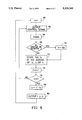
- FIG. 6 is a flow chart of a current detection method in accordance with one preferred embodiment of the present invention.
- FIG. 7a shows one descriptive example of the switching of the gate states in three carrier periods of the pulsewidth modulation control signal.
- FIG. 7b shows another descriptive example of the switching of the gate states in three carrier periods of the pulsewidth modulation control signal.
- the converter includes three pairs of transistors Q 1 , Q 4 ; Q 3 , Q 6 ; and Q 5 , Q 2 , and a driver 10 controlling the ON/OFF states of the transistors Q 1 to Q 6 in order to convert a DC source E into three-phase alternating currents T, S, and R.
- the transistors Q 1 to Q 6 shown in FIGS. 2a to 2f, 3, 4a to 4f, and 5a to 5f are indicated as switches for ease of illustration.
- the transistor pair Q 1 and Q 4 controls the voltage of the R phase; the transistor pair Q 3 and Q 6 controls the voltage of the S phase; and the transistor pair Q 5 and Q 2 controls the voltage of the T phase.
- the transistors Q.sub. 1, Q 3 , and Q 5 are defined as positive gates while the transistors Q 4 , Q 6 , and Q 2 are defined as negative gates.
- the conduction time of the positive gate in each phase are usually complementary with that of the negative gate. That is to say, when the positive gate is ON, the negative gate is always OFF, and vice versa.
- the gate state of each phase can be represented by the binary codes, i.e. 0 and 1.
- the code 0 represents that the positive gate is OFF while the negative gate is ON.
- the code 1 represents that the positive gate is ON while the negative gate is OFF.
- the three-phase gate states can be represented by three codes.
- the code combination (1, 0, 0) represents that the transistor Q 1 of the R phase is ON while the transistor Q 4 is OFF; the transistor Q 3 of the S phase is OFF while the transistor Q 6 is ON; and the transistor Q 5 of the T phase is OFF while the transistor Q 2 is ON.
- there are two three-phase gate states wherein the gate states in three phases are all the same, i.e.
- these gate states are defined as the zero state.
- the other six states besides the zero state are shown in FIGS. 2a to 2f respectively. Furthermore, they can be represented by the voltage vectors. As shown in FIG. 2, the zero state is at the origin, and the other six gate states are represented respectively by six vectors. Each two adjoining vectors of the six vectors are separated by sixty degrees, and the regions between each two adjoining vectors are labeled as regions a to f. Since these are all general principles of the so-called space vector control, it is not necessary to describe them further.
- each of the six three-phase gate states there must be one of the positive gates Q 1 , Q 3 , and Q 5 , or one of the negative gates Q 4 , Q 6 , and Q 2 in the ON state individually with respect to the other two gates.
- the transistor Q 1 is ON individually with respect to the transistors Q 3 and Q 5 , and this is indicated by the symbol R+.
- the transistor Q 2 is ON, as indicated by the symbol T-.
- the transistor Q 3 ON as indicated by S+.
- the transistor Q 4 ON as indicated by R-.
- the transistor Q 5 ON as indicated by T+.
- the transistor Q 6 ON as indicated by S-.
- the six gate states described above are symmetrical. Therefore, once all of the current paths in one of the gate states are described, the current paths of the other gate states can be easily inferred.
- FIGS. 5a to 5f there are shown all of the current paths in the fourth gate state shown in FIG. 2d. Also referring to FIG.
- the first to sixth gate states are labeled by the symbols R+, T-, S+, R-, T+, and S- respectively to represent the definition of the current flowing directions described above, as shown in FIGS. 2 and 2a to 2f.
- FIG. 3 there is shown a DC to three-phase AC converter utilizing the current detection method of the present invention.
- the circuit of FIG . 3 is quite similar to the circuit of FIG. 1. The difference therebetween is that the converter of FIG. 3 utilizes only a single DC sensor 36 connected to a detecting device 32 while omitting the two AC sensors 16 and 18 shown in FIG. 1.
- the detecting device 32 of the converter shown in FIG. 3 receives the direct current I dc sensed by the DC sensor 36, and calculates the three-phase currents I R , I S , and I T according to the method of the present invention.
- the detecting device 32 is also coupled to a control device 12 to obtain the information about the ON/OFF states of the transistors Q 1 to Q 6 .
- the specification utilizes the above-mentioned space vector control method which controls the transistors or gates by means of the pulsewidth modulation (PWM) technique to describe the current detection method of the present invention.
- PWM pulsewidth modulation
- the gate control signal in the PWM control is divided into a plurality of short time units called as carrier periods. Each carrier period is subdivided into three intervals each representing the duration of one gate state output. Therefore, there are three gate state outputs within each carrier period, and one of the gate state output is selected as the zero state (0, 0, 0) or (1, 1, 1) while the other two gate states is selected from the above-described six gate states.
- the shown angles represent the phase angles of the three-phase AC voltages in accordance with the concept of the space vector.
- an imaginary pointer rotates in a counterclockwise direction. Its rotation frequency is just equal to the frequency of the three-phase AC voltage.
- the voltage vectors within the region a, b, c, d, e, or f of FIG. 2 can be formed by means of the voltage vectors of the two gate states adjacent that region.
- all of the voltage vectors in region a can be formed by means of the R+ and T- voltage vectors; all of the voltage vectors in region b can be formed by means of the T- and S+ voltage vectors; and so on.
- FIGS. 3 and 7a there is shown one example of three carrier periods ⁇ T of the PWM signal in region a.
- two gate states are selected as the R+ (1, 0, 0) and T- (1, 1, 0) gate states, and the other is selected as the zero state.
- the durations of the three gate states are varied to form the different voltage output. It should be noted that the width variations of the intervals ⁇ t1 to ⁇ t9 shown in FIG. 7a has been exaggerated for the sake of clarity.
- the width variation would be smaller, depending on the desired formation of the output voltage.
- the currents I R and I T are sensed, and then the detecting device 32 can calculate the current I S in accordance with the following equation:
- the three-phase alternating-currents I R , I S , and I T can be detected and calculated in each of the other carrier periods, such as in the intervals ⁇ t4 to ⁇ t6 or ⁇ t7 to ⁇ t9.
- I S I dc .
- the currents I T and I S are sensed, and then the detecting device 32 can calculate the current I R .
- the three-phase alternating-currents I R , I S , and I T can be detected and calculated in each of the other carrier periods.
- a determination of whether the I dc should be changed to a negative value or not is made in the decision block 68.
- the I dc should be changed to a negative value in the block 70 if the transistors Q 1 to Q 6 are currently at the second gate state T- (1, 1, 0), the fourth gate state R- (0, 1, 1), or the sixth gate state S- (1, 0, 1).
- the direct current I dc currently sensed by the DC sensor 36 belongs to the three-phase current I R , I S , or I T , and thus the value I n is stored at the adequate address representing the I R , I S , or I T in the block 72.
- the parameter n is increased by one in the block 74, and a determination whether the parameter n is over two or not is made in the decision block 76. If it is not over two, the steps from the blocks 62 to 74 are repeated again to further detect another direct current in the same carrier period. If yes, this means that two direct currents I 1 and I 2 have been detected in one carrier period.
- the current values of the I 1 , I 2 , and I 3 i.e. the values of the three-phase alternating currents I R , I S , and I T , are output in the block 80. In this way, the current detection for one carrier period is completed. Then, the blocks from 60 to 80 are repeated once more for the current detection of next carrier period.
- the three-phase alternating currents I R , I S , and I T are detected once in one carrier period. That is to say, the first and second sensed currents of two phases are utilized to calculate the current value of the other phase; the third and fourth sensed currents of two phases are utilized to calculate the current value of the other phase; and so on.
- the present invention is not intended to be limited to this.
- any two adjoining sensed currents can be utilized to calculate the current value of the other phase.
- the second and third sensed currents can also be utilized to calculate the current value of the other phase. This totally depends on the application. Since the carrier period is very short generally, the current value calculated in this way can be treated as a correct value.
- the method of the present invention can also be achieved by an electronic circuit instead of the microprocessor incorporating the requisite software. Since such an electronic circuit can be designed easily by those skilled in the art in accordance with the method of the present invention, this is deemed unnecessary to be further described. Furthermore, the electronic circuit designed in accordance with the present invention can be configured as an ASIC or hybrid IC the cost of which could be very low as known in the art.
Abstract
A current detection method for a direct-current (DC) to three-phase alternating-current (AC) converter can utilize only a single DC sensor to detect and calculate the three-phase alternating currents. The method can detect a direct current value of one phase at each of six different gate states of three pairs of transistors in the DC to three-phase AC converter by means of the DC sensor. In the two-level pulsewidth modulation control, the control signal includes a plurality of carrier periods each being subdivided into three intervals. The three pairs of transistors are switched to the zero state in one interval of each carrier period, and to two different gate states respectively in the two other intervals. The method can detect two current values of different phases respectively in the two other intervals of each carrier period, and then calculate the current value of the other phase in accordance with the principle that the sum of the three-phase currents is always equal to zero.
Description
The present invention relates generally to a current detection method for a converter, and particularly to a current detection method for a direct-current (DC) to three-phase alternating-current (AC) converter. The method can utilize only a single DC sensor to detect and calculate the three-phase alternating currents.
Conventional converters typically have protection means for detecting over-current and over-load conditions, and for protecting the converters from damage when such conditions occur. In conventional DC to three-phase AC converters, a DC sensor and two AC sensors have to be used in order to detect the over-current and three-phase alternating currents respectively. With reference to FIG. 1, the basic circuit of a general DC to three-phase AC converter is shown. As shown in the drawing, the converter converts a DC source E into three-phase alternating currents T, S, and R which are then connected to a load (not shown), such as an induction motor. The basic circuit includes six transistors Q1 to Q6, and a driver 10 controlling the ON/OFF states of the transistors Q1 to Q6 to achieve the conversion purpose. The basic circuit further must include a DC sensor 14 for detecting the over-current to actuate a control device 12 to protect the converter, and two AC sensors 16 and 18 to detect the load currents. The sensors 14, 16, and 18 are very expensive, and thus comprise a large part of the cost of the converter.
Therefore, the primary object of the present invention is to provide a current detection method for a DC to three-phase AC converter. The method needs only a single DC sensor to detect the three-phase alternating currents, and thus the system structure of the converter is significantly simplified, resulting in a large reduction in cost.
In accordance with the present invention, a current detection method for a direct-current to three-phase alternating-current converter wherein the converter includes a direct-current sensor for detecting its direct-current, and three pairs of transistors for controlling its three-phase alternating-currents, the method comprises the steps of:
(a) controlling the switching of the gate states of the three pairs of transistors;
(b) detecting two current values of different phases respectively at two different gate states of the three pairs of transistors by means of the direct-current sensor; and
(c) calculating the current value of the other phase by means of the two detected current values of different phases.
The present invention can be more fully understood by reference to the following description and accompanying drawings, which form an integral part of this application:
FIG. 1 is a schematic diagram of the basic electrical circuit of a conventional DC to three-phase AC converter;
FIG. 2 is a schematic diagram of the voltage vectors of the basic circuit shown in FIG. 1;
FIGS. 2a to 2f show six ON/OFF state combinations of the six transistors in the basic circuit shown in FIG. 1;
FIG. 3 is a schematic diagram of one example of a DC to three-phase AC converter utilizing the current detection method of the present invention;
FIGS. 4a to 4f are schematic diagrams showing six current paths at the gate state of FIG. 2a;
FIGS. 5a to 5f are schematic diagrams showing six current paths at the gate state of FIG. 2d;
FIG. 6 is a flow chart of a current detection method in accordance with one preferred embodiment of the present invention;
FIG. 7a shows one descriptive example of the switching of the gate states in three carrier periods of the pulsewidth modulation control signal; and
FIG. 7b shows another descriptive example of the switching of the gate states in three carrier periods of the pulsewidth modulation control signal.
In order to easily understand the method of the present invention, the basic principle of a direct-current (DC) to three-phase alternating-current (AC) converter is firstly described. Referring to FIG. 1 or 3, the converter includes three pairs of transistors Q1, Q4 ; Q3, Q6 ; and Q5, Q2, and a driver 10 controlling the ON/OFF states of the transistors Q1 to Q6 in order to convert a DC source E into three-phase alternating currents T, S, and R. Please note that the transistors Q1 to Q6 shown in FIGS. 2a to 2f, 3, 4a to 4f, and 5a to 5f are indicated as switches for ease of illustration. In the circuit of the converter, the transistor pair Q1 and Q4 controls the voltage of the R phase; the transistor pair Q3 and Q6 controls the voltage of the S phase; and the transistor pair Q5 and Q2 controls the voltage of the T phase. The transistors Q.sub. 1, Q3, and Q5 are defined as positive gates while the transistors Q4, Q6, and Q2 are defined as negative gates. In the general voltage control, such as two-level pulsewidth modulation control, the conduction time of the positive gate in each phase are usually complementary with that of the negative gate. That is to say, when the positive gate is ON, the negative gate is always OFF, and vice versa. Thus, the gate state of each phase can be represented by the binary codes, i.e. 0 and 1. The code 0 represents that the positive gate is OFF while the negative gate is ON. The code 1 represents that the positive gate is ON while the negative gate is OFF. In accordance with such a definition, there are eight combinations of the gate states in three-phases R, S, and T, and the three-phase gate states can be represented by three codes. For example, the code combination (1, 0, 0) represents that the transistor Q1 of the R phase is ON while the transistor Q4 is OFF; the transistor Q3 of the S phase is OFF while the transistor Q6 is ON; and the transistor Q5 of the T phase is OFF while the transistor Q2 is ON. It should be noted that there are two three-phase gate states wherein the gate states in three phases are all the same, i.e. (0, 0, 0) and (1, 1, 1). In these two three-phase gate states, the three-phase AC end in the circuit is in a short state while the DC end is in an open state, resulting in no voltage. Thus, these gate states are defined as the zero state. The other six states besides the zero state are shown in FIGS. 2a to 2f respectively. Furthermore, they can be represented by the voltage vectors. As shown in FIG. 2, the zero state is at the origin, and the other six gate states are represented respectively by six vectors. Each two adjoining vectors of the six vectors are separated by sixty degrees, and the regions between each two adjoining vectors are labeled as regions a to f. Since these are all general principles of the so-called space vector control, it is not necessary to describe them further.
Referring now to FIGS. 2, and 2a to 2f, in each of the six three-phase gate states, there must be one of the positive gates Q1, Q3, and Q5, or one of the negative gates Q4, Q6, and Q2 in the ON state individually with respect to the other two gates. For example, in the first state shown in FIG. 2a, the transistor Q1 is ON individually with respect to the transistors Q3 and Q5, and this is indicated by the symbol R+. In the second state shown in FIG. 2b, the transistor Q2 is ON, as indicated by the symbol T-. In the third state shown in FIG. 2c, the transistor Q3 ON, as indicated by S+. In the fourth state shown in FIG. 2d, the transistor Q4 ON, as indicated by R-. In the fifth state shown in FIG. 2e, the transistor Q5 ON, as indicated by T+. In the sixth state shown in FIG. 2f, the transistor Q6 ON, as indicated by S-. Thus, the current instantaneously flowing through the turned-on gate is direct current.
Basically, the six gate states described above are symmetrical. Therefore, once all of the current paths in one of the gate states are described, the current paths of the other gate states can be easily inferred. With reference to FIGS. 4a to 4f, there are shown all of the current paths in the first gate state shown in FIG. 2a. Also referring to FIG. 3, it can be seen that the direct current Idc is equal to the current flowing out of the R phase, and thus can be defined as IR =Idc. With reference to FIGS. 5a to 5f, there are shown all of the current paths in the fourth gate state shown in FIG. 2d. Also referring to FIG. 3, it can be seen that the direct current, Idc is equal to the current flowing into the R phase, and thus can be defined as IR =-Idc. According to the same principle, it can be inferred that IT =-Idc. in the second gate state of FIG. 2 b; IT =Idc in the fifth gate state of FIG. 2e; IS =Idc in the third gate state of FIG. 2c; and IS =-Idc in the sixth gate state of FIG. 2f. For the sake of convenience, the first to sixth gate states are labeled by the symbols R+, T-, S+, R-, T+, and S- respectively to represent the definition of the current flowing directions described above, as shown in FIGS. 2 and 2a to 2f. Furthermore, the sum of the three-phase alternating currents must be equal to zero, i.e. IR +IS +IT =0, in accordance with the circuit loop shown in FIG. 1 or 3.
Referring now to FIG. 3, there is shown a DC to three-phase AC converter utilizing the current detection method of the present invention. The circuit of FIG . 3 is quite similar to the circuit of FIG. 1. The difference therebetween is that the converter of FIG. 3 utilizes only a single DC sensor 36 connected to a detecting device 32 while omitting the two AC sensors 16 and 18 shown in FIG. 1. The detecting device 32 of the converter shown in FIG. 3 receives the direct current Idc sensed by the DC sensor 36, and calculates the three-phase currents IR, IS, and IT according to the method of the present invention. The detecting device 32 is also coupled to a control device 12 to obtain the information about the ON/OFF states of the transistors Q1 to Q6.
In order to clearly understand the method of the present invention, the specification utilizes the above-mentioned space vector control method which controls the transistors or gates by means of the pulsewidth modulation (PWM) technique to describe the current detection method of the present invention. However, it should be understood that the present invention is not intended to be limited to the space vector control application. The gate control signal in the PWM control is divided into a plurality of short time units called as carrier periods. Each carrier period is subdivided into three intervals each representing the duration of one gate state output. Therefore, there are three gate state outputs within each carrier period, and one of the gate state output is selected as the zero state (0, 0, 0) or (1, 1, 1) while the other two gate states is selected from the above-described six gate states. The selection manner will be described in detail hereinafter. With reference to FIG. 2, the shown angles represent the phase angles of the three-phase AC voltages in accordance with the concept of the space vector. Thus, during operation, it can be envisioned that an imaginary pointer rotates in a counterclockwise direction. Its rotation frequency is just equal to the frequency of the three-phase AC voltage. The voltage vectors within the region a, b, c, d, e, or f of FIG. 2 can be formed by means of the voltage vectors of the two gate states adjacent that region. For example, all of the voltage vectors in region a can be formed by means of the R+ and T- voltage vectors; all of the voltage vectors in region b can be formed by means of the T- and S+ voltage vectors; and so on. Referring to FIGS. 3 and 7a, there is shown one example of three carrier periods ΔT of the PWM signal in region a. In each carrier period, two gate states are selected as the R+ (1, 0, 0) and T- (1, 1, 0) gate states, and the other is selected as the zero state. The durations of the three gate states are varied to form the different voltage output. It should be noted that the width variations of the intervals Δt1 to Δt9 shown in FIG. 7a has been exaggerated for the sake of clarity. In the actual application, the width variation would be smaller, depending on the desired formation of the output voltage. In accordance with the method of the present invention and the circuit of FIG. 3, the direct current Idc sensed by the DC sensor 36 in the interval Δt1 is equal to the IR, i.e. IR =Idc ; there is no current in the interval Δt2; and the direct current Idc sensed by the DC sensor 36 in the interval Δt3 is equal to the -IT, i.e. IT =-Idc. In this carrier period ΔT, the currents IR and IT are sensed, and then the detecting device 32 can calculate the current IS in accordance with the following equation:
I.sub.R +I.sub.S +I.sub.T =0.
According to the same principle, the three-phase alternating-currents IR, IS, and IT can be detected and calculated in each of the other carrier periods, such as in the intervals Δt4 to Δt6 or Δt7 to Δt9.
Referring now to FIGS. 3 and 7b, there is shown one example of three carrier periods ΔT of the PWM signal in the region b. In each carrier period, two gate states are selected as the T- (1, 1, 0) and S+ (0, 1, 0) gate states, and the other is selected as the zero state. In accordance with the method of the present invention and the circuit of FIG. 3, the direct current Idc sensed by the DC sensor 36 in the interval Δt1 is equal to -IT, i.e. IT =-Idc ; there is no current in the interval Δt2; and the direct current Idc sensed by the DC sensor 36 in the interval Δt3 is equal to IS, i.e. IS =Idc. In this carrier period ΔT, the currents IT and IS are sensed, and then the detecting device 32 can calculate the current IR. In the same principle, the three-phase alternating-currents IR, IS, and IT can be detected and calculated in each of the other carrier periods.
The current detection method and principle in the other regions c to f are the same, thus it is unnecessary to describe them further. Therefore, in accordance with the method of the present invention, only a single DC sensor 36 is needed to detect the three-phase alternating currents at the carrier frequency.
In accordance with the method of the present invention, the detecting device 32 of FIG. 3 can be a microprocessor incorporating appropriate software, and can be integrated within the control device 12. With reference to FIG. 6, there is shown a flowchart of the requisite software. Firstly, the parameter n is reset to one, as shown in the block 60. Then, the control signal is output to the driver 10 to switch the the gate state of the transistors Q1 to Q6, as shown in the block 62. The detecting device 32 receives the direct current Idc sensed by the DC sensor 36, and lets In =Idc, as shown in the block 64. In accordance with the control signal output in the block 62, a determination of whether the Idc should be changed to a negative value or not is made in the decision block 68. For example, the Idc should be changed to a negative value in the block 70 if the transistors Q1 to Q6 are currently at the second gate state T- (1, 1, 0), the fourth gate state R- (0, 1, 1), or the sixth gate state S- (1, 0, 1). In accordance with the control signal output in the block 62, it can be realized that the direct current Idc currently sensed by the DC sensor 36 belongs to the three-phase current IR, IS, or IT, and thus the value In is stored at the adequate address representing the IR, IS, or IT in the block 72. The parameter n is increased by one in the block 74, and a determination whether the parameter n is over two or not is made in the decision block 76. If it is not over two, the steps from the blocks 62 to 74 are repeated again to further detect another direct current in the same carrier period. If yes, this means that two direct currents I1 and I2 have been detected in one carrier period. Thus, the other direct current I3 can be calculated in the block 78, i.e. I3 is equal to -I1 -I2 in accordance with the above-mentioned equation IR +IS +IT= 0. The current values of the I1, I2, and I3, i.e. the values of the three-phase alternating currents IR, IS, and IT, are output in the block 80. In this way, the current detection for one carrier period is completed. Then, the blocks from 60 to 80 are repeated once more for the current detection of next carrier period.
In the example described in FIG. 6, the three-phase alternating currents IR, IS, and IT are detected once in one carrier period. That is to say, the first and second sensed currents of two phases are utilized to calculate the current value of the other phase; the third and fourth sensed currents of two phases are utilized to calculate the current value of the other phase; and so on. However, the present invention is not intended to be limited to this. For example, any two adjoining sensed currents can be utilized to calculate the current value of the other phase. That is to say, the second and third sensed currents can also be utilized to calculate the current value of the other phase. This totally depends on the application. Since the carrier period is very short generally, the current value calculated in this way can be treated as a correct value.
The method of the present invention can also be achieved by an electronic circuit instead of the microprocessor incorporating the requisite software. Since such an electronic circuit can be designed easily by those skilled in the art in accordance with the method of the present invention, this is deemed unnecessary to be further described. Furthermore, the electronic circuit designed in accordance with the present invention can be configured as an ASIC or hybrid IC the cost of which could be very low as known in the art.
While the invention has been described in terms of what is presently considered to be the most practical and preferred embodiments, it is to be understood that the invention need not be limited to the disclosed embodiments. On the contrary, it is intended to cover various modifications and similar arrangements included within the spirit and scope of the appended claims, the scope of which should be accorded the broadest interpretation so as to encompass all such modifications and similar structures.
Claims (12)
1. A current detection method for a direct-current to three-phase alternating-current converter wherein said converter includes a direct current power supply, a direct-current sensor for detecting direct-current on the direct current side of the converter, three pairs of transistors for converting the direct current power supply to a three phase alternating current power supply, and a control means to control a sequenced switching of the transistors and the resulting three-phase alternating-currents, said method comprising the steps of:
(a) controlling the switching of said three pairs of transistors;
(b) detecting direct current values in the direct current side of the converter corresponding to the phase current of a first phase and a second phase by means of said direct-current sensor; and
(c) calculating a phase current value for a third phase by means of said detected current values of the first and second phases.
2. A current detection method as claimed in claim 1, wherein said controlling of the switching of the three pairs of transistors includes generating a two-level pulsewidth modulation control signal to control the switching of each pair of transistors.
3. A current detection method as claimed in claim 2, wherein said controlling the switching of the three pairs of transistors includes the steps of:
producing a two-level pulsewidth modulation control signal including a plurality of carrier periods, each carrier period having three switching intervals;
controlling the switching of each pair of transistors at a zero state in a first interval of each carrier period; and
controlling the switching of each pair of transistors at two different operating states in second and third intervals of each carrier period.
4. A current detection method as claimed in claim 3, wherein said detecting two direct current values in the direct current side of the converter corresponding to the phase current of a first phase and a second phase includes the step of:
monitoring the operating and zero states of the three pairs of transistors during the three intervals of each carrier period;
detecting said direct current values of the two operating states during each carrier period by means of said direct current sensor.
5. The current detection method as claimed in claim 3 wherein the step of controlling the switching of each pair of transistors includes transmitting a zero state and two operating states of a space vector control system by utilizing the pulsewidth modulated signals generated by the control means.
6. The current detection method as claimed in claim 1 wherein calculating a phase current value for a third phase (I3) by means of said detected current values of the first and second phases (I1 +I2) includes inserting the detected current values for the two known phases into the equation I1 +I2 +I3 =0 and solving the equation for the value of the third phase.
7. A current detection method for a direct current to three-phase alternating current converter wherein said converter includes a direct current power supply, a direct current sensor for detecting current on the direct current side of the converter, three pairs of transistors for converting the direct current power supply to a three phase alternating current power supply, a driver to control a sequenced switching of the transistors to generate the three-phase alternating currents, and a detecting device for determining and monitoring the direct current and the three phase currents in the converter, said method comprising the steps of:
(a) generating a pulsewidth modulation control signal with a pluarlity of space vector designations to control the switching of said three pairs of transistors and produce a three phase alternating current output;
(b) detecting a first direct current value (I1) in the direct current side of the converter corresponding to the phase current of a first phase of said three pairs of transistors;
(c) monitoring the state of the three pair of transistors to distinguish the first phase, and storing the first direct current value in the detecting device;
(d) detecting a second direct current value (I2) in the direct current side of the converter corresponding to the phase current of a second phase of said three pairs of transistors;
(e) monitoring the state of the three pair of transistors to distinguish the second phase, and storing the second direct current value in the detecting device;
(f) calculating a third phase current value (I3) by solving the equation I1 +I2 +I3 =0 for the third phase current value.
8. A current detection method as claimed in claim 7, wherein the step of generating a pulsewidth modulated control signal includes generating a signal having a plurality of carrier periods for controlling the switching of the pairs of transistors, each carrier period including two variable-length operating intervals and one variable zero state intervals, whereby the state of the transistors is monitored and the value of the current is detected for the first phase and the second phase during the two operating intervals of the carrier period.
9. A current detection method as claimed in claim 8, wherein the method includes the additional steps of repeating the process for determining all three phase currents for each carrier period.
10. An apparatus for determining currents in a six transistor DC to AC converter, including measurement of the direct current in a DC circuit of the converter, measurement of two alternating current phases, and calculation of a third alternating current phase in an AC circuit of the converter, said apparatus comprising:
(a) a DC current sensor mounted on the DC circuit of the converter for measuring the direct current in the DC circuit of the converter and for generating an output signal;
(b) driver means electrically connected to six transistors in the converter for controlling the on-off switching of the six transistors in the converter by the generation of a pulsewidth modulated signal;
(c) control means for processing and transmitting control signals, said control means being connected to said driver means to control the sequencing of the transistors to generate a desired AC output, and including an over current protection circuit to protect the converter; and
(d) a detecting device electrically connected to said DC current sensor and said control means, said detecting device including a processing means for processing signals from the DC current sensor and for processing signals from said control means, whereby said control means sequences the switching of the transistors in the converter to permit indirect current measurement of a first and a second alternating current phase by said DC current sensor, and calculation of a third alternating current phase by the processing means in said detecting device.
11. The apparatus defined in claim 10 wherein the processing means in said detecting device includes a microprocessor with appropriate software for storing information about two of the alternating current phases, and calculating the third alternating current phase.
12. The apparatus defined in claim 10 wherein the processing means in said detecting device includes an integrated circuit.
Priority Applications (1)
| Application Number | Priority Date | Filing Date | Title |
|---|---|---|---|
| US07/949,070 US5309349A (en) | 1992-09-22 | 1992-09-22 | Current detection method for DC to three-phase converters using a single DC sensor |
Applications Claiming Priority (1)
| Application Number | Priority Date | Filing Date | Title |
|---|---|---|---|
| US07/949,070 US5309349A (en) | 1992-09-22 | 1992-09-22 | Current detection method for DC to three-phase converters using a single DC sensor |
Publications (1)
| Publication Number | Publication Date |
|---|---|
| US5309349A true US5309349A (en) | 1994-05-03 |
Family
ID=25488559
Family Applications (1)
| Application Number | Title | Priority Date | Filing Date |
|---|---|---|---|
| US07/949,070 Expired - Lifetime US5309349A (en) | 1992-09-22 | 1992-09-22 | Current detection method for DC to three-phase converters using a single DC sensor |
Country Status (1)
| Country | Link |
|---|---|
| US (1) | US5309349A (en) |
Cited By (40)
| Publication number | Priority date | Publication date | Assignee | Title |
|---|---|---|---|---|
| WO1996023347A1 (en) * | 1995-01-23 | 1996-08-01 | Danfoss A/S | A method for measuring phase currents in an inverter |
| US5552977A (en) * | 1995-06-20 | 1996-09-03 | Ford Motor Company | Three phase inverter circuit with improved transition from SVPWM to six step operation |
| EP0822648A1 (en) * | 1996-07-30 | 1998-02-04 | Texas Instruments France | Method and device for control of invertors |
| US6069808A (en) * | 1997-05-21 | 2000-05-30 | Texas Instruments Incorporated | Symmetrical space vector PWM DC-AC converter controller |
| US6154379A (en) * | 1998-07-16 | 2000-11-28 | Tdk Corporation | Electric power conversion device |
| US6456946B1 (en) | 2000-02-25 | 2002-09-24 | Motorola, Inc. | System and method for motor fault detection |
| US6479971B1 (en) * | 1998-01-30 | 2002-11-12 | Schroedl Manfred | Method for regulating a three-phase machine without a mechanical rotary transducer |
| US20030173946A1 (en) * | 2002-03-15 | 2003-09-18 | Guang Liu | Procedure for measuring the current in each phase of a three-phase device via single current sensor |
| WO2003105329A1 (en) * | 2002-06-07 | 2003-12-18 | Trw Limited | Motor drive control with a single current sensor using space vector technique |
| US6718273B1 (en) * | 1999-06-22 | 2004-04-06 | Robert Bosch Gmbh | Methods for simplified field-oriented control of asynchronous machines |
| US20040103740A1 (en) * | 2002-09-26 | 2004-06-03 | Townsend William T. | Intelligent, self-contained robotic hand |
| US20040125622A1 (en) * | 2002-12-25 | 2004-07-01 | Daisuke Hirono | Current detection unit of inverter |
| US20040189316A1 (en) * | 2003-03-26 | 2004-09-30 | Lg Industrial Systems Co., Ltd. | Method of diagnosing inverter trouble |
| US6856137B2 (en) * | 2002-02-19 | 2005-02-15 | Bae Systems Controls Inc. | Ground fault detection system and method |
| EP1553692A2 (en) * | 2003-12-19 | 2005-07-13 | ABB Oy | Method for determining output currents of frequency converter |
| US20050248361A1 (en) * | 2004-05-10 | 2005-11-10 | O'gorman Patrick A | Damping control in a three-phase motor with a single current sensor |
| US20060071622A1 (en) * | 2002-09-26 | 2006-04-06 | Townsend William T | Ultra-compact, high-performance motor controller and method of using same |
| WO2006058808A1 (en) * | 2004-11-30 | 2006-06-08 | Robert Bosch Gmbh | Method for measuring current using a shunt and measuring current device |
| EP1722470A2 (en) | 2005-05-13 | 2006-11-15 | Schrödl, Manfred | Method and circuit configuration for approximate adjustment of a voltage space vector |
| US20060274469A1 (en) * | 2005-06-06 | 2006-12-07 | Texas Instruments Incorporated | Apparatus and method for controlling provision of power to a load by a plurality of generating devices |
| US20070085546A1 (en) * | 2005-10-19 | 2007-04-19 | Abb Oy | Method and arrangement for measuring inverter output currents |
| EP1863160A2 (en) * | 2006-06-01 | 2007-12-05 | Vacon Oyj | Measurement of the current of a frequency converter |
| EP1950882A2 (en) | 2007-01-26 | 2008-07-30 | Siemens Aktiengesellschaft | Method and device for operating a rotating current machine controllable through pulse width modulation with multiple phase coils |
| US20080180095A1 (en) * | 2007-01-17 | 2008-07-31 | Stmicroelectronics S.R.L. | Method and related device for estimating the currents flowing in windings of a poly-phase electrical load at a certain instant |
| EP2003758A1 (en) * | 2007-06-15 | 2008-12-17 | Hitachi Appliances, Inc. | Power conversion apparatus and module including the power conversion apparatus |
| US20090212733A1 (en) * | 2008-02-27 | 2009-08-27 | Tung-Chin Hsieh | To Obtain the Three-Phase Current via adjusting width of pulses with Single DC-Link Current Sensor |
| WO2009124798A1 (en) * | 2008-04-07 | 2009-10-15 | Robert Bosch Gmbh | Method and device for current measurement in phase lines |
| US20100165674A1 (en) * | 2008-12-30 | 2010-07-01 | Rockwell Automation Technologies, Inc. | Power conversion systems and methods for controlling harmonic distortion |
| US20100270964A1 (en) * | 2007-03-27 | 2010-10-28 | Danfoss Drives A/S | Method for driving a pulse width modulated controller |
| EP2360483A1 (en) * | 2010-01-25 | 2011-08-24 | Robert Bosch GmbH | Method and device for electricity measurement in a multi-phase electricity network |
| EP2385384A1 (en) | 2010-05-03 | 2011-11-09 | Vacon Oyj | The measuring of earth fault current |
| DE102011003897A1 (en) * | 2011-02-10 | 2012-08-16 | Robert Bosch Gmbh | Method and device for current measurement |
| US8907611B2 (en) | 2011-07-14 | 2014-12-09 | Texas Instruments Incorporated | Method and apparatus for space vector pulse width modulation of a three-phase current construction with single DC-link shunt |
| CN106597070A (en) * | 2015-10-20 | 2017-04-26 | 施耐德电气It公司 | Current sensing system for full-bridge pulse-width modulated inverter system |
| US10148155B2 (en) | 2013-12-04 | 2018-12-04 | Barrett Technology, Llc | Method and apparatus for connecting an ultracompact, high-performance motor controller to an ultracompact, high-performance brushless DC motor |
| US10320323B1 (en) | 2018-03-28 | 2019-06-11 | Infineon Technologies Austria Ag | Pulse width modulation (PWM) scheme for single shunt motor control |
| US10514398B2 (en) | 2013-12-04 | 2019-12-24 | Schneider Electric It Corporation | Inverter regulation |
| EP1715573B1 (en) * | 2005-04-20 | 2020-06-17 | Brose Fahrzeugteile SE & Co. Kommanditgesellschaft, Würzburg | Method and device for driving electrical loads |
| US11474260B1 (en) * | 2021-05-26 | 2022-10-18 | Beken Corporation | Apparatus and method of generating Weil codes |
| US20230132524A1 (en) * | 2021-10-28 | 2023-05-04 | Delta Electronics, Inc. | Method of controlling power converter and power converter |
Citations (15)
| Publication number | Priority date | Publication date | Assignee | Title |
|---|---|---|---|---|
| US4099225A (en) * | 1976-07-19 | 1978-07-04 | Danfoss A/S | Protective circuit for an inverter |
| US4180853A (en) * | 1978-08-23 | 1979-12-25 | United Technologies Corporation | Two-stage commutation circuit for an inverter |
| US4752866A (en) * | 1985-04-22 | 1988-06-21 | National Distillers And Chemical Corporation | Ozonator power supply employing a current source inverter |
| US4788485A (en) * | 1986-03-24 | 1988-11-29 | Mitsubishi Denki Kabushiki Kaisha | Apparatus for controlling electric motor |
| US4823065A (en) * | 1986-05-21 | 1989-04-18 | La Telemecanique Electrique | Frequency converter for the stabilized power supply of asynchronous motors |
| US4870556A (en) * | 1986-01-11 | 1989-09-26 | Hitachi, Ltd. | Method and apparatus for controlling power converter |
| US4896242A (en) * | 1988-07-18 | 1990-01-23 | Westinghouse Electric Corp. | Direct AC-DC converter fault protection system |
| US4988939A (en) * | 1989-08-04 | 1991-01-29 | Thor Technology Corporation | Electric motor with variable commutation delay |
| US5084812A (en) * | 1989-10-19 | 1992-01-28 | Asea Brown Boveri Ltd. | Arrangement for converting two single-phase alternating currents into a symmetric three-phase current |
| US5127085A (en) * | 1991-04-01 | 1992-06-30 | General Motors Corporation | Ride-through protection circuit for a voltage source inverter traction motor drive |
| US5163172A (en) * | 1988-11-14 | 1992-11-10 | Kone Elevator Gmbh | Procedure and apparatus for the measurement of the currents in a frequency converter |
| US5177677A (en) * | 1989-03-08 | 1993-01-05 | Hitachi, Ltd. | Power conversion system |
| US5177428A (en) * | 1990-09-12 | 1993-01-05 | Kabushiki Kaisha Toshiba | Inverter control device capable of supressing dc magnetization in three-phase transformer |
| US5202621A (en) * | 1989-03-09 | 1993-04-13 | Siemens Aktiengesellschaft Osterreich | Current transformer arrangement for three-wire three-phase systems to detect the actual current value for controlled dc loads powered via power converters |
| US5214575A (en) * | 1990-12-14 | 1993-05-25 | Mitsubishi Denki Kabushiki Kaisha | Ground fault detector for an inverter and a method therefor |
-
1992
- 1992-09-22 US US07/949,070 patent/US5309349A/en not_active Expired - Lifetime
Patent Citations (15)
| Publication number | Priority date | Publication date | Assignee | Title |
|---|---|---|---|---|
| US4099225A (en) * | 1976-07-19 | 1978-07-04 | Danfoss A/S | Protective circuit for an inverter |
| US4180853A (en) * | 1978-08-23 | 1979-12-25 | United Technologies Corporation | Two-stage commutation circuit for an inverter |
| US4752866A (en) * | 1985-04-22 | 1988-06-21 | National Distillers And Chemical Corporation | Ozonator power supply employing a current source inverter |
| US4870556A (en) * | 1986-01-11 | 1989-09-26 | Hitachi, Ltd. | Method and apparatus for controlling power converter |
| US4788485A (en) * | 1986-03-24 | 1988-11-29 | Mitsubishi Denki Kabushiki Kaisha | Apparatus for controlling electric motor |
| US4823065A (en) * | 1986-05-21 | 1989-04-18 | La Telemecanique Electrique | Frequency converter for the stabilized power supply of asynchronous motors |
| US4896242A (en) * | 1988-07-18 | 1990-01-23 | Westinghouse Electric Corp. | Direct AC-DC converter fault protection system |
| US5163172A (en) * | 1988-11-14 | 1992-11-10 | Kone Elevator Gmbh | Procedure and apparatus for the measurement of the currents in a frequency converter |
| US5177677A (en) * | 1989-03-08 | 1993-01-05 | Hitachi, Ltd. | Power conversion system |
| US5202621A (en) * | 1989-03-09 | 1993-04-13 | Siemens Aktiengesellschaft Osterreich | Current transformer arrangement for three-wire three-phase systems to detect the actual current value for controlled dc loads powered via power converters |
| US4988939A (en) * | 1989-08-04 | 1991-01-29 | Thor Technology Corporation | Electric motor with variable commutation delay |
| US5084812A (en) * | 1989-10-19 | 1992-01-28 | Asea Brown Boveri Ltd. | Arrangement for converting two single-phase alternating currents into a symmetric three-phase current |
| US5177428A (en) * | 1990-09-12 | 1993-01-05 | Kabushiki Kaisha Toshiba | Inverter control device capable of supressing dc magnetization in three-phase transformer |
| US5214575A (en) * | 1990-12-14 | 1993-05-25 | Mitsubishi Denki Kabushiki Kaisha | Ground fault detector for an inverter and a method therefor |
| US5127085A (en) * | 1991-04-01 | 1992-06-30 | General Motors Corporation | Ride-through protection circuit for a voltage source inverter traction motor drive |
Cited By (88)
| Publication number | Priority date | Publication date | Assignee | Title |
|---|---|---|---|---|
| CN1063596C (en) * | 1995-01-23 | 2001-03-21 | 丹福斯有限公司 | Method for measuring phase currents in inverter |
| GB2313202A (en) * | 1995-01-23 | 1997-11-19 | Danfoss As | A method for measuring phase currents in an inverter |
| GB2313202B (en) * | 1995-01-23 | 1999-09-22 | Danfoss As | A method for measuring phase currents in an inverter |
| US5969958A (en) * | 1995-01-23 | 1999-10-19 | Danfoss | Method for measuring phase currents in an inverter |
| WO1996023347A1 (en) * | 1995-01-23 | 1996-08-01 | Danfoss A/S | A method for measuring phase currents in an inverter |
| US5552977A (en) * | 1995-06-20 | 1996-09-03 | Ford Motor Company | Three phase inverter circuit with improved transition from SVPWM to six step operation |
| EP0822648A1 (en) * | 1996-07-30 | 1998-02-04 | Texas Instruments France | Method and device for control of invertors |
| FR2752111A1 (en) * | 1996-07-30 | 1998-02-06 | Texas Instruments France | METHOD AND DEVICE FOR CONTROLLING INVERTERS |
| US6049474A (en) * | 1996-07-30 | 2000-04-11 | Texas Instruments Incorporated | Current estimator for a three phase invertor with PWM period adjustment |
| US6069808A (en) * | 1997-05-21 | 2000-05-30 | Texas Instruments Incorporated | Symmetrical space vector PWM DC-AC converter controller |
| US6479971B1 (en) * | 1998-01-30 | 2002-11-12 | Schroedl Manfred | Method for regulating a three-phase machine without a mechanical rotary transducer |
| US6154379A (en) * | 1998-07-16 | 2000-11-28 | Tdk Corporation | Electric power conversion device |
| US6718273B1 (en) * | 1999-06-22 | 2004-04-06 | Robert Bosch Gmbh | Methods for simplified field-oriented control of asynchronous machines |
| US6456946B1 (en) | 2000-02-25 | 2002-09-24 | Motorola, Inc. | System and method for motor fault detection |
| US6856137B2 (en) * | 2002-02-19 | 2005-02-15 | Bae Systems Controls Inc. | Ground fault detection system and method |
| EP1347567A1 (en) * | 2002-03-15 | 2003-09-24 | Motorola, Inc. | Procedure for measuring the current in each phase of a three phase device via single current sensor |
| EP1347566A1 (en) * | 2002-03-15 | 2003-09-24 | Motorola, Inc. | Procedure for measuring the current in each phase of a three-phase device via a single current sensor |
| US6735537B2 (en) * | 2002-03-15 | 2004-05-11 | Motorola, Inc. | Procedure for measuring the current in each phase of a three-phase device via single current sensor |
| US20030173946A1 (en) * | 2002-03-15 | 2003-09-18 | Guang Liu | Procedure for measuring the current in each phase of a three-phase device via single current sensor |
| WO2003105329A1 (en) * | 2002-06-07 | 2003-12-18 | Trw Limited | Motor drive control with a single current sensor using space vector technique |
| US7612522B2 (en) | 2002-06-07 | 2009-11-03 | Trw Limited | Motor drive control with a single current sensor using space vector technique |
| US20080079377A1 (en) * | 2002-06-07 | 2008-04-03 | Williams Connel B | Motor drive control with a single current sensor using space vector technique |
| CN100566112C (en) * | 2002-06-07 | 2009-12-02 | Trw有限公司 | Be used to comprise the drive system of heterogeneous heterogeneous brushless motor |
| EP1589650A3 (en) * | 2002-06-07 | 2006-11-22 | TRW Limited | Motor drive control |
| EP1589650A2 (en) * | 2002-06-07 | 2005-10-26 | TRW Limited | Motor drive control |
| KR101068353B1 (en) | 2002-06-07 | 2011-09-30 | 티알더블유 오토모티브 유.에스.엘엘씨 | Motor drive control with a single current sensor using space vector technique |
| US7893644B2 (en) | 2002-09-26 | 2011-02-22 | Barrett Technology, Inc. | Ultra-compact, high-performance motor controller and method of using same |
| US20090295317A1 (en) * | 2002-09-26 | 2009-12-03 | Barrett Technology, Inc. | Ultra-compact, high-performance motor controller and method of using same |
| US20060071622A1 (en) * | 2002-09-26 | 2006-04-06 | Townsend William T | Ultra-compact, high-performance motor controller and method of using same |
| US7511443B2 (en) | 2002-09-26 | 2009-03-31 | Barrett Technology, Inc. | Ultra-compact, high-performance motor controller and method of using same |
| US20040103740A1 (en) * | 2002-09-26 | 2004-06-03 | Townsend William T. | Intelligent, self-contained robotic hand |
| US20090289584A1 (en) * | 2002-09-26 | 2009-11-26 | Barrett Technology, Inc. | Ultra-compact, high-performance motor controller and method of using same |
| US7854631B2 (en) | 2002-09-26 | 2010-12-21 | Barrett Technology, Inc. | Ultra-compact, high-performance motor controller |
| US7168748B2 (en) | 2002-09-26 | 2007-01-30 | Barrett Technology, Inc. | Intelligent, self-contained robotic hand |
| US20040125622A1 (en) * | 2002-12-25 | 2004-07-01 | Daisuke Hirono | Current detection unit of inverter |
| US7042191B2 (en) * | 2002-12-25 | 2006-05-09 | Sanden Corporation | Current detection unit of inverter |
| CN100459398C (en) * | 2002-12-25 | 2009-02-04 | 三电有限公司 | Current detecting unit for inverter |
| US20040189316A1 (en) * | 2003-03-26 | 2004-09-30 | Lg Industrial Systems Co., Ltd. | Method of diagnosing inverter trouble |
| US7068037B2 (en) * | 2003-03-26 | 2006-06-27 | Lg Industrial Systems Co., Ltd. | Method of diagnosing inverter trouble |
| EP1553692A2 (en) * | 2003-12-19 | 2005-07-13 | ABB Oy | Method for determining output currents of frequency converter |
| US7190599B2 (en) | 2003-12-19 | 2007-03-13 | Abb Oy | Method for determining output currents of frequency converter |
| EP1553692A3 (en) * | 2003-12-19 | 2005-08-03 | ABB Oy | Method for determining output currents of frequency converter |
| US20050152165A1 (en) * | 2003-12-19 | 2005-07-14 | Panu Virolainen | Method for determining output currents of frequency converter |
| US7414425B2 (en) | 2004-05-10 | 2008-08-19 | Temic Automotive Of North America, Inc. | Damping control in a three-phase motor with a single current sensor |
| US20050248361A1 (en) * | 2004-05-10 | 2005-11-10 | O'gorman Patrick A | Damping control in a three-phase motor with a single current sensor |
| WO2006058808A1 (en) * | 2004-11-30 | 2006-06-08 | Robert Bosch Gmbh | Method for measuring current using a shunt and measuring current device |
| EP1715573B1 (en) * | 2005-04-20 | 2020-06-17 | Brose Fahrzeugteile SE & Co. Kommanditgesellschaft, Würzburg | Method and device for driving electrical loads |
| EP1722470A2 (en) | 2005-05-13 | 2006-11-15 | Schrödl, Manfred | Method and circuit configuration for approximate adjustment of a voltage space vector |
| US7667349B2 (en) * | 2005-06-06 | 2010-02-23 | Texas Instruments Incorporated | Providing power to a load by controlling a plurality of generating devices |
| US20060274469A1 (en) * | 2005-06-06 | 2006-12-07 | Texas Instruments Incorporated | Apparatus and method for controlling provision of power to a load by a plurality of generating devices |
| US7508688B2 (en) * | 2005-10-19 | 2009-03-24 | Abb Oy | Method and arrangement for measuring output phase currents of a voltage source inverter under a load |
| US20070085546A1 (en) * | 2005-10-19 | 2007-04-19 | Abb Oy | Method and arrangement for measuring inverter output currents |
| EP1863160A3 (en) * | 2006-06-01 | 2017-03-29 | Vacon Oy | Measurement of the current of a frequency converter |
| EP1863160A2 (en) * | 2006-06-01 | 2007-12-05 | Vacon Oyj | Measurement of the current of a frequency converter |
| US7728538B2 (en) * | 2007-01-17 | 2010-06-01 | Stmicroelectronics S.R.L. | Method and related device for estimating the currents flowing in windings of a poly-phase electrical load at a certain instant |
| US20080180095A1 (en) * | 2007-01-17 | 2008-07-31 | Stmicroelectronics S.R.L. | Method and related device for estimating the currents flowing in windings of a poly-phase electrical load at a certain instant |
| EP1950882A3 (en) * | 2007-01-26 | 2010-06-02 | Siemens Aktiengesellschaft | Method and device for operating a rotating current machine controllable through pulse width modulation with multiple phase coils |
| US20080191660A1 (en) * | 2007-01-26 | 2008-08-14 | Siemens Aktiengesellschaft | Method and device for controlling a three-phase machine having several phase windings, which can be controlled by means of pulse width modulation |
| EP1950882A2 (en) | 2007-01-26 | 2008-07-30 | Siemens Aktiengesellschaft | Method and device for operating a rotating current machine controllable through pulse width modulation with multiple phase coils |
| US7906929B2 (en) | 2007-01-26 | 2011-03-15 | Siemens Aktiengesellschaft | Method and device for controlling a three-phase machine having several phase windings, which can be controlled by means of pulse width modulation |
| US20100270964A1 (en) * | 2007-03-27 | 2010-10-28 | Danfoss Drives A/S | Method for driving a pulse width modulated controller |
| US8648561B2 (en) | 2007-03-27 | 2014-02-11 | Danfoss Drives A/S | Method for driving a pulse width modulated controller |
| EP2003758A1 (en) * | 2007-06-15 | 2008-12-17 | Hitachi Appliances, Inc. | Power conversion apparatus and module including the power conversion apparatus |
| US7898210B2 (en) | 2008-02-27 | 2011-03-01 | Prolific Technology Inc. | To obtain the three-phase current via adjusting width of pulses with single DC-link current sensor |
| US20090212733A1 (en) * | 2008-02-27 | 2009-08-27 | Tung-Chin Hsieh | To Obtain the Three-Phase Current via adjusting width of pulses with Single DC-Link Current Sensor |
| JP2011516871A (en) * | 2008-04-07 | 2011-05-26 | ローベルト ボツシユ ゲゼルシヤフト ミツト ベシユレンクテル ハフツング | Method and apparatus for current measurement in phase wires |
| CN102057281A (en) * | 2008-04-07 | 2011-05-11 | 罗伯特.博世有限公司 | Method and device for current measurement in phase lines |
| US20110057641A1 (en) * | 2008-04-07 | 2011-03-10 | Sven Finke | Method and apparatus for current measurement in phase lines |
| US8618789B2 (en) | 2008-04-07 | 2013-12-31 | Robert Bosch Gmbh | Method and apparatus of offset error compensation for current measurement in phase lines of a multiphase current network |
| WO2009124798A1 (en) * | 2008-04-07 | 2009-10-15 | Robert Bosch Gmbh | Method and device for current measurement in phase lines |
| US8044631B2 (en) * | 2008-12-30 | 2011-10-25 | Rockwell Automation Technologies, Inc. | Power conversion systems and methods for controlling harmonic distortion |
| CN101789702B (en) * | 2008-12-30 | 2014-09-03 | 洛克威尔自动控制技术股份有限公司 | Power conversion systems and methods for controlling harmonic distortion |
| US20100165674A1 (en) * | 2008-12-30 | 2010-07-01 | Rockwell Automation Technologies, Inc. | Power conversion systems and methods for controlling harmonic distortion |
| EP2360483A1 (en) * | 2010-01-25 | 2011-08-24 | Robert Bosch GmbH | Method and device for electricity measurement in a multi-phase electricity network |
| EP2385384A1 (en) | 2010-05-03 | 2011-11-09 | Vacon Oyj | The measuring of earth fault current |
| CN102288801A (en) * | 2010-05-03 | 2011-12-21 | 瓦孔厄伊公司 | Measuring of earth fault current |
| US8645087B2 (en) | 2010-05-03 | 2014-02-04 | Vacon Oyj | Measuring of earth fault current |
| DE102011003897A1 (en) * | 2011-02-10 | 2012-08-16 | Robert Bosch Gmbh | Method and device for current measurement |
| US8907611B2 (en) | 2011-07-14 | 2014-12-09 | Texas Instruments Incorporated | Method and apparatus for space vector pulse width modulation of a three-phase current construction with single DC-link shunt |
| US10148155B2 (en) | 2013-12-04 | 2018-12-04 | Barrett Technology, Llc | Method and apparatus for connecting an ultracompact, high-performance motor controller to an ultracompact, high-performance brushless DC motor |
| US10514398B2 (en) | 2013-12-04 | 2019-12-24 | Schneider Electric It Corporation | Inverter regulation |
| CN106597070A (en) * | 2015-10-20 | 2017-04-26 | 施耐德电气It公司 | Current sensing system for full-bridge pulse-width modulated inverter system |
| EP3160033A3 (en) * | 2015-10-20 | 2017-06-14 | Schneider Electric IT Corporation | Current sensing system for full-bridge pulse-width modulated inverter system |
| US10637369B2 (en) | 2015-10-20 | 2020-04-28 | Schneider Electric It Corporation | Current sensing system for full-bridge pulse-width modulated inverter system |
| US10320323B1 (en) | 2018-03-28 | 2019-06-11 | Infineon Technologies Austria Ag | Pulse width modulation (PWM) scheme for single shunt motor control |
| US11474260B1 (en) * | 2021-05-26 | 2022-10-18 | Beken Corporation | Apparatus and method of generating Weil codes |
| US20230132524A1 (en) * | 2021-10-28 | 2023-05-04 | Delta Electronics, Inc. | Method of controlling power converter and power converter |
| US11711029B2 (en) * | 2021-10-28 | 2023-07-25 | Delta Electronics, Inc. | Method of controlling power converter and power converter |
Similar Documents
| Publication | Publication Date | Title |
|---|---|---|
| US5309349A (en) | Current detection method for DC to three-phase converters using a single DC sensor | |
| KR100272395B1 (en) | Multi-coupled power converter and its controlling method | |
| EP1322028B1 (en) | Voltage conversion system and method and recording medium | |
| JP2563226B2 (en) | Current sensing method for converter | |
| JP5163734B2 (en) | 3-level inverter | |
| US20040095090A1 (en) | Method of detecting motor current and motor control device | |
| US6556464B2 (en) | PWM converter system | |
| US10128739B2 (en) | Power conversion device | |
| US8283880B2 (en) | Motor drive device with function of switching to power regenerative operation mode | |
| KR880001837B1 (en) | Induction motor | |
| KR100960043B1 (en) | Apparatus and method for controlling space voltage vector in two-phase synchronous permanent magnet motor | |
| US20150131351A1 (en) | Modulation Of Switching Signals In Power Converters | |
| US20100117576A1 (en) | Motor driver | |
| KR20040024446A (en) | Control device for an electric motor | |
| JP2006246649A (en) | Inverter device | |
| US11303224B2 (en) | Inverter device with high follow-up capability | |
| JP6332297B2 (en) | Power converter | |
| US8284577B2 (en) | Method for operation of a converter circuit, and apparatus for carrying out the method | |
| JP2004064864A (en) | Controller of elevator | |
| JP2007116817A (en) | Inverter control circuit | |
| US6885569B2 (en) | Energy converting device | |
| Wolbank et al. | Scheme to reconstruct phase current information of inverter fed AC drives | |
| JP4448294B2 (en) | Power converter | |
| JP2003164185A (en) | Three-phase ac motor control device | |
| RU200602U1 (en) | ELECTRIC DRIVE WITH CYCLO-CONVERTER |
Legal Events
| Date | Code | Title | Description |
|---|---|---|---|
| AS | Assignment |
Owner name: INDUSTRIAL TECHNOLOGY RESEARCH INSTITUTE, TAIWAN Free format text: ASSIGNMENT OF ASSIGNORS INTEREST.;ASSIGNOR:KWAN, KHANG-SHEN;REEL/FRAME:006324/0868 Effective date: 19920915 |
|
| STCF | Information on status: patent grant |
Free format text: PATENTED CASE |
|
| FPAY | Fee payment |
Year of fee payment: 4 |
|
| FPAY | Fee payment |
Year of fee payment: 8 |
|
| FPAY | Fee payment |
Year of fee payment: 12 |