US5307771A - Motorcycle air cleaner - Google Patents
Motorcycle air cleaner Download PDFInfo
- Publication number
- US5307771A US5307771A US07/843,990 US84399092A US5307771A US 5307771 A US5307771 A US 5307771A US 84399092 A US84399092 A US 84399092A US 5307771 A US5307771 A US 5307771A
- Authority
- US
- United States
- Prior art keywords
- port
- housing
- air
- carburetor
- air intake
- Prior art date
- Legal status (The legal status is an assumption and is not a legal conclusion. Google has not performed a legal analysis and makes no representation as to the accuracy of the status listed.)
- Expired - Lifetime
Links
Images


Classifications
-
- F—MECHANICAL ENGINEERING; LIGHTING; HEATING; WEAPONS; BLASTING
- F02—COMBUSTION ENGINES; HOT-GAS OR COMBUSTION-PRODUCT ENGINE PLANTS
- F02M—SUPPLYING COMBUSTION ENGINES IN GENERAL WITH COMBUSTIBLE MIXTURES OR CONSTITUENTS THEREOF
- F02M35/00—Combustion-air cleaners, air intakes, intake silencers, or induction systems specially adapted for, or arranged on, internal-combustion engines
- F02M35/10—Air intakes; Induction systems
- F02M35/10006—Air intakes; Induction systems characterised by the position of elements of the air intake system in direction of the air intake flow, i.e. between ambient air inlet and supply to the combustion chamber
- F02M35/10013—Means upstream of the air filter; Connection to the ambient air
-
- F—MECHANICAL ENGINEERING; LIGHTING; HEATING; WEAPONS; BLASTING
- F02—COMBUSTION ENGINES; HOT-GAS OR COMBUSTION-PRODUCT ENGINE PLANTS
- F02M—SUPPLYING COMBUSTION ENGINES IN GENERAL WITH COMBUSTIBLE MIXTURES OR CONSTITUENTS THEREOF
- F02M35/00—Combustion-air cleaners, air intakes, intake silencers, or induction systems specially adapted for, or arranged on, internal-combustion engines
- F02M35/10—Air intakes; Induction systems
- F02M35/10242—Devices or means connected to or integrated into air intakes; Air intakes combined with other engine or vehicle parts
- F02M35/10255—Arrangements of valves; Multi-way valves
-
- F—MECHANICAL ENGINEERING; LIGHTING; HEATING; WEAPONS; BLASTING
- F02—COMBUSTION ENGINES; HOT-GAS OR COMBUSTION-PRODUCT ENGINE PLANTS
- F02M—SUPPLYING COMBUSTION ENGINES IN GENERAL WITH COMBUSTIBLE MIXTURES OR CONSTITUENTS THEREOF
- F02M35/00—Combustion-air cleaners, air intakes, intake silencers, or induction systems specially adapted for, or arranged on, internal-combustion engines
- F02M35/16—Combustion-air cleaners, air intakes, intake silencers, or induction systems specially adapted for, or arranged on, internal-combustion engines characterised by use in vehicles
- F02M35/162—Motorcycles; All-terrain vehicles, e.g. quads, snowmobiles; Small vehicles, e.g. forklifts
-
- F—MECHANICAL ENGINEERING; LIGHTING; HEATING; WEAPONS; BLASTING
- F02—COMBUSTION ENGINES; HOT-GAS OR COMBUSTION-PRODUCT ENGINE PLANTS
- F02B—INTERNAL-COMBUSTION PISTON ENGINES; COMBUSTION ENGINES IN GENERAL
- F02B61/00—Adaptations of engines for driving vehicles or for driving propellers; Combinations of engines with gearing
- F02B61/06—Combinations of engines with mechanical gearing
-
- F—MECHANICAL ENGINEERING; LIGHTING; HEATING; WEAPONS; BLASTING
- F02—COMBUSTION ENGINES; HOT-GAS OR COMBUSTION-PRODUCT ENGINE PLANTS
- F02M—SUPPLYING COMBUSTION ENGINES IN GENERAL WITH COMBUSTIBLE MIXTURES OR CONSTITUENTS THEREOF
- F02M35/00—Combustion-air cleaners, air intakes, intake silencers, or induction systems specially adapted for, or arranged on, internal-combustion engines
- F02M35/02—Air cleaners
Definitions
- the present invention relates to internal combustion engines.
- the present invention relates to an air intake system for an internal combustion engine.
- Internal combustion engines operate by creating a controlled combustion of a mixture of fuel and air within a cylinder of the engine. Ultimately the energy produced by this combustion is transmitted to a drive shaft or other means for providing a locomotive force to gear or wheel.
- a carburetor typically performs this task.
- the carburetor selectively guides the flow of air and fuel into a main conduit of the carburetor where the air and fuel are mixed into the inflammable gas. This gas mixture is then delivered to a cylinder of the engine for combustion therein.
- the air intake system for a carburetor typically has an air filter positioned outside of the main conduit. This air filter removes undesirable particles, such as dirt and oil, from the air as the air is passing from the outside environment into the carburetor.
- the air filter is encompassed within a housing which covers the air filter and directs the flow of air into and through the air filter. Once the air passes through the air filter, it passes down into a mouth of the carburetor.
- the horsepower produced by an engine is limited in part as a function of the air-fuel mixture ratio.
- One way of increasing the horsepower of the engine is by providing a greater amount of air available for mixing with the fuel.
- the air must be provided to the carburetor without over pressurizing the carburetor float bowl which would impede engine performance.
- Some known methods of increasing the horsepower of an engine by augmenting the air that enters the carburetor include supercharging and turbocharging.
- the amount of air entering the carburetor is typically limited by the fixed configuration of the intake openings in the air filter housing. These openings are sized and positioned to direct an adequate amount of air through the air filter and into the carburetor without over pressurizing the carburetor float bowl.
- the housings usually do not provide a means for selectively closing the openings or selectively varying the amount of air permitted to flow through the housing (and ultimately the carburetor).
- An intake assembly of the present invention delivers air to a carburetor of an internal combustion engine.
- the assembly includes a housing mountable on the carburetor and which encloses an air filter.
- a first port is formed within a wall of the housing to permit fluid communication between the housing and the carburetor.
- the first port is positioned between the air filter and the carburetor.
- a second port is formed in a wall of the housing to permit air to enter the housing.
- the second port is positioned relative to the air filter on a side opposite from the first port.
- a valve assembly is pivotably mounted within the second port such that the valve assembly is positionable to control a flow of air through the second port. Means are provided for controlling the pivoting of the valve assembly.
- the air cleaner of the present invention facilitates varying engine performance by controlling the amount of air flowing into the carburetor.
- the present invention permits the rate of air flowing into the air cleaner and carburetor to be changed as a function of a vacuum supplied from the internal combustion engine.
- a third port is formed within a wall of the housing to permit air to enter and exit the housing.
- the third port is positioned relative to the air filter on a side opposite from the first port.
- the third port is located at a point closer to the air filter than the second port. This third port aids in balancing the air flow into and out of the air filter to manage the balance of air entering the mouth of the carburetor and exiting a venting channel of the carburetor.
- the means for positioning the valve assembly is a rod having one end connected to the valve assembly and another end connected to a diaphragm of a vacuum chamber.
- a spring of the vacuum chamber biases the rod to keep the valve assembly in an open position when no vacuum is being applied and in a closed position when a vacuum is drawing on the diaphragm.
- the third port is closed to further accentuate the increased flow of air being forced into the carburetor by the present invention.
- appropriate modifications of the carburetor and other systems of the engine must be made to permit the air cleaner to facilitate the increased air flow into the carburetor without simultaneously upsetting the proper balance of the air flow entering and exiting the carburetor.
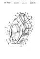
- FIG. 1 is a perspective view of the air cleaner of the present invention with a valve assembly in the open position.
- FIG. 2A is sectional view along line 2A--2A of FIG. 1 illustrating an air cleaner of the present invention as implemented with a carburetor of an internal combustion engine.
- FIG. 2B is a fragmentary detail of the view shown in FIG. 2A except with a diaphragm shown in a position caused by a vacuum.
- FIG. 3 is a plan view of a side of the air cleaner for facing the carburetor.
- FIG. 4 is a perspective view of the air cleaner of FIG. 2 with the valve assembly in a closed position.
- FIG. 5 is a perspective view of the air cleaner with the diaphragm assembly shown in a exploded view.
- FIG. 6 is a perspective view of the air cleaner as in FIG. 1 except without a side port.
- FIGS. 1 and 2A An air cleaner of the present invention is illustrated generally at 10 in FIGS. 1 and 2A.
- the air cleaner 10 is mounted onto a carburetor 12 of an internal combustion engine 14 of a motorcycle by use of a bracket 16 (see also FIG. 5).
- the air cleaner 10 has a housing 18 having a first portion 20 and a second portion 22.
- the housing 18 is preferably made of a chrome plated steel.
- a circularly-shaped air deflection plate 24 is secured within an opening 25 in a wall of the first portion 20.
- a circularly-shaped port opening 30 is formed in a wall of the second portion 22 of housing 18.
- the second portion 22 also has a plurality of openings 32 disposed about the port 30 for use with a fastener means 31 (FIG. 2A) to secure the housing 18 to the bracket 16 and carburetor 12.
- a carburetor vent port opening 34 is positioned about the port 30 and is shaped similar to openings 32. As seen in FIGS.
- a longitudinally shaped slot port opening 36 is formed in a side wall 38 of housing 18.
- the port opening 36 can be formed by a plurality of circularly shaped openings or differently shaped openings sufficient to allow air to enter the housing 18 and to allow water (or other liquid) to escape the housing 18 through port 36.
- the first port 30 provides a path (indicated by arrow A) for fluid communication from the housing 18 into a mouth 39 of carburetor 12.
- the vent port 34 provides a path for fluid communication in a direction opposite from path A (indicated by arrow B) from a vent channel (not shown) of the carburetor 12 into the housing 18.
- An air filter 40 is contained within the housing 18 of air cleaner 10.
- the air filter 40 is annularly shaped and has an inner wall 42 and an outer wall 44. A radius of the inner wall 42 of filter 40 is greater than a radius of the first port 30.
- a main port opening 50 is formed in a mouth portion 52 of the housing 18.
- the mouth portion 52 includes a stem 54 that separates the port opening 50 into two portions.
- a valve assembly 55 is disposed within the mouth portion 52 of housing 18.
- the valve assembly 55 includes a pivoting rod 56 and a pair of valve plates 60.
- the pivoting rod 56 extends a width of the mouth portion 52 and is pivotally mounted through stem 54 and the side wall 38 of housing 18.
- a pair of rings 57 (only one shown) are respectively mounted about each end of the pivoting rod 56 to facilitate rotation of the rod 56 relative to the side wall 38.
- the pair of ventilation valve plates 60 are generally oval shaped and are connected to the pivoting rod 56 such that one of each of the valve plates 60 is positioned within one of the two openings of the main port 50.
- the generally oval shape of the valve plates 60 closely fits within the shape of the two main port openings 50 such that a close tolerance is maintained between an edge of the plates 60 and an edge of the main port openings 50.
- the valve plates 60 can be circularly shaped or rectangularly shaped with the main port openings 50 accordingly shaped to accommodate the shape of the valve plates 60 while still maintaining the close tolerance.
- a diaphragm assembly 70 of the air cleaner 10 is disposed on an outer wall 72 of the second portion 22 of housing 18.
- the diaphragm assembly 70 includes a cylinder 74 extending outwardly from the outer wall 72.
- the cylinder 74 has a first end 76 and second end 78 with the first end encompassing a circularly shaped opening 75 formed in the outer wall 72 of the housing 18.
- a flexible round diaphragm 82 is secured within the first end 76 of the cylinder 74 to cover the opening 75.
- the diaphragm 82 is preferably made of a soft flexible rubber material.
- a rod 84 of the diaphragm assembly 70 has a first end 86 and a second end 88.
- the first end 86 of the rod 84 extends through the opening 75 and a center of the diaphragm 82 and is connected thereto by a suitable fastening means such as multipart fastener 89.
- the second end 88 of the rod 84 extends in the opposite direction into the mouth portion 52 of the housing 18.
- the second end 88 of the rod 84 is bent relative to the first end 86 and is connected to the pivoting rod 56 at a midway point between the two valve plates 60.
- the rod 84 is aligned with the stem 54 so that the rod is not readily visible from outside the mouth portion 52 of housing 18 (FIG. 1).
- a vacuum sealing ring 90 of the diaphragm assembly 70 is disposed within the cylinder 70 and is positioned over the diaphragm 82.
- the ring 90 has a stem valve 92 (FIGS. 3 and 5) for connecting the ring 90 to a vacuum supply 93 (schematically illustrated in FIG. 3) of the internal combustion engine 14.
- the vacuum supply 93 can be provided from a vacuum chamber in the carburetor (not shown) or from some other suitable vacuum system of the internal combustion engine 14.
- a coil spring 94 of the diaphragm assembly 70 (FIGS. 2A, 2B, and 5) has a first end 96 secured to the fastener 89.
- a second end 98 of the spring 94 is constrained by a cover 100.
- the cover 100 includes a sealing gasket 102 and is secured onto the second end 78 of cylinder 74 by a suitable fastening means such as fasteners 103 to create a sealed chamber 104 therein.
- the sealing gasket 102 is preferably made of a hard rubber material.
- the cover 100 also includes an adjustment screw 106 has an end 107 which extends into the sealed chamber 104 to contact fastener 89 (see FIG. 2B).
- the cover 100, sealing gasket 102, and cylinder 74 can be integrally connected to simplify the construction of some of the components forming the diaphragm assembly 70.
- the air cleaner 10 is normally oriented relative to the engine 16 so that the main port 50 faces the direction in which the motorcycle moves. In this orientation, the pivoting rod 56 is aligned vertically relative to the ground (a horizontal axis). This orientation provides a direct path for air flowing along side a moving motorcycle to enter the air cleaner 10 and flow into the air filter 10.
- the bracket 16 has a plurality of elongate slots 108 for mounting the air cleaner 10 thereon. The elongation of the slots permits the housing 18 of air cleaner 10 to be rotated slightly upward or downward relative to its normal position when fastened to the bracket 16 such that the main port 50 would respectively be facing slightly upward or downward relative to the ground.
- the air cleaner 10 When mounted to an internal combustion engine 14, the air cleaner 10 provides an effective and aesthetically pleasing air intake mechanism for a carburetor 12.
- the air cleaner 10 filters air before it flows into the carburetor for mixing with fuel.
- the air takes a different path into the air cleaner 10 depending upon whether the valve plates 60 are in an open position (FIG. 1 and 2A), or in a closed position (FIG. 4), or in a partially open/closed position (FIG. 2B).
- the position of the valve plates 60 is dictated by operation of the diaphragm assembly 70.
- the diaphragm assembly is controlled by the vacuum supply 93 which selectively applies a vacuum on the diaphragm assembly 70.
- the spring 94 is biased to maintain the diaphragm 82 and rod 84 in the position shown in FIGS. 1 and 2A, i.e., maintaining the valve plates 60 in an open position. This allows air to flow through the main port openings 50 of the mouth portion 52 of housing 18.
- a vacuum is present on the diaphragm assembly 70 such that the valve plates 60 are in a substantially closed position (see FIG. 2B), or in a fully closed position (FIG. 4).
- valve plates 60 When operating the engine 14 at full throttle, no significant vacuum is exerted on the diaphragm assembly 70 such that the air cleaner 10 operates in same manner as when the engine 14 is being started.
- the valve plates 60 are in an open position (FIG. 2) allowing air to enter the main port openings 50.
- the valve plates 60 may be oriented in a range of partially open/closed positions between the extremes of the open position (no vacuum) and the closed position (full vacuum).
- the range of open/closed positions can also be controlled by use of the adjustment screw 106.
- the valve assembly 55 By positioning the end 107 of the screw 106 further within the sealed chamber 104, the valve assembly 55 will be prevented from reaching the fully closed position (illustrated in FIG. 4) but instead will reach a position similar to that shown in FIG. 2B.
- the end 107 of the screw 106 acts a stop to prevent the fastener 89 (and the diaphragm 82) from moving any closer to the cover 100. This ultimately limits the extent to which the valve assembly 55 is permitted to rotate toward a closed position.
- valve assembly 55 (and diaphragm assembly 70) is not mechanically linked to the throttle control of the engine 14 but is controlled by a vacuum supplied by the vacuum supply 93 and which acts on the diaphragm assembly 70.
- a throttle control can be used to control the operation of the valve assembly 55 by establishing a mechanical linkage between the throttle control and the valve assembly 55.
- using the vacuum control diaphragm assembly 70 to control the positioning of the valve plates 60 has distinct advantages over a mechanically based throttle control.
- using a vacuum control avoids placing an additional load on the throttle cable. This provides an important ergonomic benefit of preventing fatigue on the arm/wrist of the motorcycle operator that would occur if the throttle cable were loaded with an additional linkage to control the valve assembly 55. This additional linkage also would be more likely to require maintenance.
- using a vacuum control establishes a more direct relationship between the demand for air by the engine and the appropriate positioning of the valve assembly 55 than with a mechanical throttle control.
- the air cleaner 10 of the present invention facilitates varying engine performance by controlling the amount of air flowing into the carburetor 12.
- a motorcycle having an internal combustion engine with the air cleaner 10 of the present invention and moving at a fast speed, i.e., with full throttle (no vacuum), will realize a substantially increased amount of air flowing into the air filter 40 and carburetor 12.
- the air cleaner 10 can be modified as shown in FIG. 6. As shown, the slot port 36 has been eliminated. This forces more of the air entering the main port 50 to flow into the carburetor 12 than in the embodiment of the air cleaner 10 having the slot port 36.
- the vent port 34 and carburetor vent channel (not shown) also would be eliminated and some other venting means for the carburetor would be required to maintain the proper balance of air entering and exiting the carburetor 12. For example, a remotely located vent for a carburetor float chamber could be provided.
- the air cleaner 10 of the present invention includes several features that accentuate the aesthetic appearance of the cycle.
- the housing 18 is chrome plated, offering a shiny look to the air cleaner 10.
- the air deflection plate 24 is colored (e.g. red or blue) to match or compliment a primary color of the cycle.
- the valve plates 60 may be similarly colored to match the color of the air deflection plate 24.
- a pair of blood grooves 110 can be formed on an outer wall 72 of the housing 18 to provide a unique texture to the surface of the housing 18.
- the air cleaner 10 of the present invention also offers other advantages.
- the air deflection plate 24 acts as an access cover for the housing 18.
- the plate 24 can be removed to expose the interior of the housing 18 so that one can access the mouth 39 of the carburetor 12 or the inner wall 42 of the air filter 40.
- This ability to access the interior of the housing 18 provides easy serviceability by permitting an operator to examine the air filter or add fluid to the carburetor, as well as perform any other necessary maintenance.
- Having a removable access cover plate 24 also provides access to the fastener openings 32 to permit the air cleaner 10 to be mounted to the carburetor 12 without disassembling the housing 18 into its two separate portions 20 and 22.
- Another advantage of the air cleaner 10 of the present invention is the manner of mounting the diaphragm assembly 70 on the housing 18.
- the diaphragm assembly 70 is uniquely positioned on the outer wall 72 of second portion 22 of housing 18 so that the assembly 70 faces the engine 14. This accentuates the aesthetic appearance of the air cleaner 10 as seen by an observer looking at the first portion (20) side of the housing 18.
- mounting the diaphragm assembly 70 in this way also permits the rod 84 to be centered between the two valve plates 60, thereby simplifying the rod linkage extending from the diaphragm 82 for controlling rotation of the ventilation plates 60. This provides a much simpler and efficient rod linkage than if the diaphragm assembly were mounted on the side wall 38 of the housing 18.
Abstract
Description
Claims (26)
Priority Applications (1)
| Application Number | Priority Date | Filing Date | Title |
|---|---|---|---|
| US07/843,990 US5307771A (en) | 1992-02-28 | 1992-02-28 | Motorcycle air cleaner |
Applications Claiming Priority (1)
| Application Number | Priority Date | Filing Date | Title |
|---|---|---|---|
| US07/843,990 US5307771A (en) | 1992-02-28 | 1992-02-28 | Motorcycle air cleaner |
Publications (1)
| Publication Number | Publication Date |
|---|---|
| US5307771A true US5307771A (en) | 1994-05-03 |
Family
ID=25291495
Family Applications (1)
| Application Number | Title | Priority Date | Filing Date |
|---|---|---|---|
| US07/843,990 Expired - Lifetime US5307771A (en) | 1992-02-28 | 1992-02-28 | Motorcycle air cleaner |
Country Status (1)
| Country | Link |
|---|---|
| US (1) | US5307771A (en) |
Cited By (22)
| Publication number | Priority date | Publication date | Assignee | Title |
|---|---|---|---|---|
| EP0793008A2 (en) * | 1996-02-28 | 1997-09-03 | Suzuki Kabushiki Kaisha | Intake apparatus of internal combustion engine |
| WO2000077387A1 (en) * | 1999-06-09 | 2000-12-21 | Volkswagen Aktiengesellschaft | Air-intake system for an internal combustion engine |
| US6216661B1 (en) | 1999-04-01 | 2001-04-17 | Randy Pickens | Filtered carburetor cover |
| US6422201B1 (en) * | 1999-09-02 | 2002-07-23 | Honda Giken Kogyo Kabushiki Kaisha | Intake control system for engine |
| US6790251B1 (en) | 2003-01-30 | 2004-09-14 | Stephen H. Brady, Jr. | Skull-shaped air filter housing |
| EP1464825A2 (en) | 2003-03-31 | 2004-10-06 | HONDA MOTOR CO., Ltd. | Intake apparatus for engine |
| US7051824B1 (en) | 2003-11-03 | 2006-05-30 | Accessible Technologies, Inc. | Supercharged motorcycle |
| US20060144377A1 (en) * | 2004-12-30 | 2006-07-06 | Lee Hsin-Chih C | Device for heightening engine efficiency |
| US7114476B1 (en) | 2005-06-27 | 2006-10-03 | Wimmer Lee S | Carburetor intake assembly for motorcycles |
| US20060288673A1 (en) * | 2005-06-27 | 2006-12-28 | Wimmer Lee S | Velocity stack air filtration assembly |
| EP1859984A1 (en) * | 2006-05-23 | 2007-11-28 | Engineering and More | Combustive air intake assembly for motorcycle and motorcycle equipped with such an assembly |
| US20080083393A1 (en) * | 2006-10-09 | 2008-04-10 | Schmidt Gregory R | Active air intake for an engine |
| US7549493B1 (en) | 2006-02-28 | 2009-06-23 | Jones Daniel W | Wet belt supercharger drive for a motorcycle |
| US20100224158A1 (en) * | 2009-03-04 | 2010-09-09 | Oakes Philip A | Air intake device |
| US8652238B2 (en) | 2012-02-27 | 2014-02-18 | John Campbell JAMES | Air directing device for motorcycles |
| EP2679796A3 (en) * | 2011-10-27 | 2014-04-30 | C.R.F. Società Consortile per Azioni | Intake assembly for an internal combustion engine |
| US8904986B1 (en) | 2014-02-28 | 2014-12-09 | John Campbell JAMES | Air directing device for motorcycles |
| USD850984S1 (en) * | 2017-06-05 | 2019-06-11 | Kuryakyn Holdings, LLC | Hypercharger |
| USD871271S1 (en) * | 2018-08-20 | 2019-12-31 | Harley-Davidson Motor Company Group, LLC | Motorcycle engine air intake |
| USD890900S1 (en) * | 2017-10-06 | 2020-07-21 | Kohler Co. | Air cleaner cover |
| US10760536B2 (en) | 2017-10-27 | 2020-09-01 | Indian Motorcycle International, LLC | Air box for a vehicle |
| USD895487S1 (en) | 2018-08-20 | 2020-09-08 | Harley-Davidson Motor Company Group, LLC | Motorcycle |
Citations (1)
| Publication number | Priority date | Publication date | Assignee | Title |
|---|---|---|---|---|
| US4008700A (en) * | 1973-08-01 | 1977-02-22 | Societe Industrielle De Brevets Et D'etudes S.I.B.E. | Fuel feed device for internal combustion engine |
-
1992
- 1992-02-28 US US07/843,990 patent/US5307771A/en not_active Expired - Lifetime
Patent Citations (1)
| Publication number | Priority date | Publication date | Assignee | Title |
|---|---|---|---|---|
| US4008700A (en) * | 1973-08-01 | 1977-02-22 | Societe Industrielle De Brevets Et D'etudes S.I.B.E. | Fuel feed device for internal combustion engine |
Non-Patent Citations (6)
| Title |
|---|
| American Motorcycles, , pp. 165 166, Chrome Specialties 1991/1992. * |
| American Motorcycles, , pp. 165-166, Chrome Specialties 1991/1992. |
| Drag Specialties, Feb. 1992, pp. 81, 82 and 462, The Personal Touch. * |
| Specialty Parts & Accessories, Fall/Winter 1991, p. 353, The Street Scoop II. * |
| Specialty Parts & Accessories, Spring 1992, p. 339, All Cast Aluminum Competition Air Scoop. * |
| The Harley Davidson Motor Co. 1992 Genuine Accessories Catalog, pp. 81 and 119. * |
Cited By (33)
| Publication number | Priority date | Publication date | Assignee | Title |
|---|---|---|---|---|
| EP0793008A2 (en) * | 1996-02-28 | 1997-09-03 | Suzuki Kabushiki Kaisha | Intake apparatus of internal combustion engine |
| EP0793008A3 (en) * | 1996-02-28 | 1998-04-01 | Suzuki Kabushiki Kaisha | Intake apparatus of internal combustion engine |
| US6216661B1 (en) | 1999-04-01 | 2001-04-17 | Randy Pickens | Filtered carburetor cover |
| WO2000077387A1 (en) * | 1999-06-09 | 2000-12-21 | Volkswagen Aktiengesellschaft | Air-intake system for an internal combustion engine |
| EP1310662A3 (en) * | 1999-09-02 | 2005-04-13 | Honda Giken Kogyo Kabushiki Kaisha | Intake control system for engine |
| EP1310662A2 (en) * | 1999-09-02 | 2003-05-14 | Honda Giken Kogyo Kabushiki Kaisha | Intake control system for engine |
| US6422201B1 (en) * | 1999-09-02 | 2002-07-23 | Honda Giken Kogyo Kabushiki Kaisha | Intake control system for engine |
| US6790251B1 (en) | 2003-01-30 | 2004-09-14 | Stephen H. Brady, Jr. | Skull-shaped air filter housing |
| EP1464825A2 (en) | 2003-03-31 | 2004-10-06 | HONDA MOTOR CO., Ltd. | Intake apparatus for engine |
| EP1464825A3 (en) * | 2003-03-31 | 2009-05-27 | HONDA MOTOR CO., Ltd. | Intake apparatus for engine |
| US7051824B1 (en) | 2003-11-03 | 2006-05-30 | Accessible Technologies, Inc. | Supercharged motorcycle |
| US20060144377A1 (en) * | 2004-12-30 | 2006-07-06 | Lee Hsin-Chih C | Device for heightening engine efficiency |
| US7100588B2 (en) * | 2004-12-30 | 2006-09-05 | Hsin-Chih Chung Lee | Device for heightening engine efficiency |
| US7114476B1 (en) | 2005-06-27 | 2006-10-03 | Wimmer Lee S | Carburetor intake assembly for motorcycles |
| US20060288673A1 (en) * | 2005-06-27 | 2006-12-28 | Wimmer Lee S | Velocity stack air filtration assembly |
| US7549493B1 (en) | 2006-02-28 | 2009-06-23 | Jones Daniel W | Wet belt supercharger drive for a motorcycle |
| FR2901512A1 (en) * | 2006-05-23 | 2007-11-30 | Engineering And More Soc Par A | COMBUSTION AIR INTAKE ASSEMBLY FOR MOTORCYCLE AND MOTORCYCLE EQUIPPED WITH SUCH AN ASSEMBLY |
| US7530417B2 (en) * | 2006-05-23 | 2009-05-12 | Engineering And More | Assembly for admitting combustion air for a motorcycle, and a motorcycle fitted with such an assembly |
| US20070272198A1 (en) * | 2006-05-23 | 2007-11-29 | Engineering And More | Assembly for admitting combustion air for a motorcycle, and a motorcycle fitted with such an assembly |
| EP1859984A1 (en) * | 2006-05-23 | 2007-11-28 | Engineering and More | Combustive air intake assembly for motorcycle and motorcycle equipped with such an assembly |
| US20080083393A1 (en) * | 2006-10-09 | 2008-04-10 | Schmidt Gregory R | Active air intake for an engine |
| US7401590B2 (en) | 2006-10-09 | 2008-07-22 | Harley-Davidson Motor Company Group, Inc. | Active air intake for an engine |
| US20100224158A1 (en) * | 2009-03-04 | 2010-09-09 | Oakes Philip A | Air intake device |
| US8201535B2 (en) | 2009-03-04 | 2012-06-19 | Honda Motor Company, Ltd. | Air intake device |
| EP2679796A3 (en) * | 2011-10-27 | 2014-04-30 | C.R.F. Società Consortile per Azioni | Intake assembly for an internal combustion engine |
| US8652238B2 (en) | 2012-02-27 | 2014-02-18 | John Campbell JAMES | Air directing device for motorcycles |
| US8904986B1 (en) | 2014-02-28 | 2014-12-09 | John Campbell JAMES | Air directing device for motorcycles |
| USD850984S1 (en) * | 2017-06-05 | 2019-06-11 | Kuryakyn Holdings, LLC | Hypercharger |
| USD890900S1 (en) * | 2017-10-06 | 2020-07-21 | Kohler Co. | Air cleaner cover |
| USD943635S1 (en) | 2017-10-06 | 2022-02-15 | Kohler Co. | Air cleaner cover and engine incorporating the same |
| US10760536B2 (en) | 2017-10-27 | 2020-09-01 | Indian Motorcycle International, LLC | Air box for a vehicle |
| USD871271S1 (en) * | 2018-08-20 | 2019-12-31 | Harley-Davidson Motor Company Group, LLC | Motorcycle engine air intake |
| USD895487S1 (en) | 2018-08-20 | 2020-09-08 | Harley-Davidson Motor Company Group, LLC | Motorcycle |
Similar Documents
| Publication | Publication Date | Title |
|---|---|---|
| US5307771A (en) | Motorcycle air cleaner | |
| EP1221545A3 (en) | Carburettors for two-stroke engines | |
| CA1194743A (en) | Pressure balanced flow regulator for gaseous fuel engine | |
| US6135429A (en) | Carburetor with automatic fuel enrichment | |
| US5692931A (en) | Control arrangement for outboard motor | |
| US6986340B2 (en) | Automatic fuel vent closure and fuel shutoff apparatus having mechanical actuation | |
| CA2450110A1 (en) | Air intake device for engine | |
| US6725822B2 (en) | Intake system for multi-cylinder engine | |
| US4446940A (en) | Speed control system for motor vehicle equipped with turbocharger | |
| US5740779A (en) | Apparatus for reducing evaporative hydrocarbon fuel emissions from an internal combustion engine and for improving the performance thereof | |
| US3741737A (en) | Gas carburetor | |
| EP1286040A2 (en) | Fuel metering assembly for a diaphragm-type carburetor | |
| EP1116865B1 (en) | Structure of mounting of exhaust gas sampling pipe in outboard engine system | |
| EP0053822A2 (en) | Improved induction system for supercharged engine | |
| CA2331207C (en) | Outboard engine system | |
| US4392472A (en) | Induction system for supercharged engine | |
| JP2003502560A (en) | Intake device for internal combustion engine | |
| US20010008818A1 (en) | Outboard engine system | |
| CA1134226A (en) | Apparatus for alternate liquid or gaseous fuel operation of internal combustion engines | |
| GB1589835A (en) | Internal combustion engines | |
| US4364367A (en) | Linkage mechanism for supercharger system | |
| JPH0247591B2 (en) | ||
| CA2331159C (en) | Passage wall cooling structure in outboard engine system | |
| JPH0231565Y2 (en) | ||
| CA1100834A (en) | Carburetor for internal combustion engine |
Legal Events
| Date | Code | Title | Description |
|---|---|---|---|
| AS | Assignment |
Owner name: KURYAKYN HOLDINGS, INC. A CORP. OF WI, WISCONSI Free format text: ASSIGNMENT OF ASSIGNORS INTEREST.;ASSIGNORS:STAHEL, ALWIN J. II;RUDD, THOMAS H.;STAHEL, BRIAN K.;REEL/FRAME:006392/0408 Effective date: 19920425 |
|
| STCF | Information on status: patent grant |
Free format text: PATENTED CASE |
|
| FEPP | Fee payment procedure |
Free format text: PAYOR NUMBER ASSIGNED (ORIGINAL EVENT CODE: ASPN); ENTITY STATUS OF PATENT OWNER: LARGE ENTITY |
|
| FPAY | Fee payment |
Year of fee payment: 4 |
|
| FPAY | Fee payment |
Year of fee payment: 8 |
|
| AS | Assignment |
Owner name: PRUDENTIAL INSURANCE COMPANY OF AMERICA, THE, CALI Free format text: SECURITY AGREEMENT;ASSIGNOR:KURYAKYN HOLDINGS, INC.;REEL/FRAME:012785/0409 Effective date: 20010105 |
|
| AS | Assignment |
Owner name: KURYAKYN HOLDINGS, INC., CALIFORNIA Free format text: RELEASE OF SECURITY INTEREST;ASSIGNOR:PRUDENTIAL INSURANCE COMPANY OF AMERICA, THE;REEL/FRAME:013000/0215 Effective date: 20020612 |
|
| AS | Assignment |
Owner name: ANTARES CAPITAL CORPORATION, AS AGENT, ILLINOIS Free format text: SECURITY AGREEMENT;ASSIGNOR:KURYAKYN HOLDINGS, INC.;REEL/FRAME:013203/0017 Effective date: 20020612 |
|
| FEPP | Fee payment procedure |
Free format text: PAT HOLDER NO LONGER CLAIMS SMALL ENTITY STATUS, ENTITY STATUS SET TO UNDISCOUNTED (ORIGINAL EVENT CODE: STOL); ENTITY STATUS OF PATENT OWNER: LARGE ENTITY |
|
| REFU | Refund |
Free format text: REFUND - PAYMENT OF MAINTENANCE FEE, 12TH YR, SMALL ENTITY (ORIGINAL EVENT CODE: R2553); ENTITY STATUS OF PATENT OWNER: LARGE ENTITY |
|
| AS | Assignment |
Owner name: KURYAKYN HOLDINGS, INC., WISCONSIN Free format text: PATENT RELEASE & REASSIGNMENT;ASSIGNOR:ANTARES CAPITAL CORPORATION, AS AGENT;REEL/FRAME:016087/0494 Effective date: 20041217 |
|
| AS | Assignment |
Owner name: CANADIAN IMPERIAL BANK OF COMMERCE, AS ADMINISTRAT Free format text: SECURITY AGREEMENT;ASSIGNORS:KURYAKYN HOLDINGS, INC.;WHITE BROTHERS PERFORMANCE PRODUCTS, INC.;PROGRESSIVE SUSPENSION, INC.;REEL/FRAME:016105/0689 Effective date: 20041217 |
|
| FPAY | Fee payment |
Year of fee payment: 12 |
|
| AS | Assignment |
Owner name: GOLDMAN SACHS CREDIT PARTNERS L.P., AS COLLATERAL Free format text: GRANT OF PATENT SECURITY INTEREST (UNDER THE PATENT SECURITY AGREEMENT);ASSIGNOR:WHITE BROTHERS PERFORMANCE PRODUCTS, INC.; V&H PERFORMANCE, INC.; KURYAKYN HOLDINGS, INC; PROGRESSIVE SUSPENSION, INC. AND PERFORMANCE MACHINE, INC.;REEL/FRAME:018590/0851 Effective date: 20061130 Owner name: WHITE BROTHERS PERFORMANCE PRODUCTS, INC.; KURYAKY Free format text: RELEASE OF SECURED PARTY'S PATENT SECURITY INTEREST IN PATENTS ORIGINALLY RECORDED ON REEL/FRAME;ASSIGNOR:CANADIAN IMPERIAL BANK OF COMMERCE, AS ADMINISTRATIVE AGENT;REEL/FRAME:018590/0802 Effective date: 20061130 |
|
| FEPP | Fee payment procedure |
Free format text: PAYOR NUMBER ASSIGNED (ORIGINAL EVENT CODE: ASPN); ENTITY STATUS OF PATENT OWNER: LARGE ENTITY Free format text: PAYER NUMBER DE-ASSIGNED (ORIGINAL EVENT CODE: RMPN); ENTITY STATUS OF PATENT OWNER: LARGE ENTITY |
|
| AS | Assignment |
Owner name: WHITE BROTHERS PERFORMANCE PRODUCTS, INC., CALIFOR Free format text: RELEASE OF SECURITY AGREEMENT IN PATENTS RECORDED AT REEL/FRAME 018590/0851;ASSIGNOR:GOLDMAN SACHS CREDIT PARTNERS L.P.;REEL/FRAME:027956/0086 Effective date: 20120326 Owner name: PROGRESSIVE SUSPENSION, LLC, CALIFORNIA Free format text: RELEASE OF SECURITY AGREEMENT IN PATENTS RECORDED AT REEL/FRAME 018590/0851;ASSIGNOR:GOLDMAN SACHS CREDIT PARTNERS L.P.;REEL/FRAME:027956/0086 Effective date: 20120326 Owner name: PERFORMANCE MACHINE, LLC, CALIFORNIA Free format text: RELEASE OF SECURITY AGREEMENT IN PATENTS RECORDED AT REEL/FRAME 018590/0851;ASSIGNOR:GOLDMAN SACHS CREDIT PARTNERS L.P.;REEL/FRAME:027956/0086 Effective date: 20120326 Owner name: KURYAKYN HOLDINGS, LLC, WISCONSIN Free format text: RELEASE OF SECURITY AGREEMENT IN PATENTS RECORDED AT REEL/FRAME 018590/0851;ASSIGNOR:GOLDMAN SACHS CREDIT PARTNERS L.P.;REEL/FRAME:027956/0086 Effective date: 20120326 Owner name: V&H PERFORMANCE, LLC, CALIFORNIA Free format text: RELEASE OF SECURITY AGREEMENT IN PATENTS RECORDED AT REEL/FRAME 018590/0851;ASSIGNOR:GOLDMAN SACHS CREDIT PARTNERS L.P.;REEL/FRAME:027956/0086 Effective date: 20120326 Owner name: WILMINGTON TRUST, NATIONAL ASSOCIATION, MINNESOTA Free format text: PATENT SECURITY AGREEMENT;ASSIGNORS:KURYAKYN HOLDINGS, LLC;MOTORSPORT AFTERMARKET GROUP, INC.;PERFORMANCE MACHINE, LLC;AND OTHERS;REEL/FRAME:027956/0133 Effective date: 20120326 |
|
| AS | Assignment |
Owner name: GENERAL ELECTRIC CAPITAL CORPORATION, AS ADMINISTR Free format text: PATENT SECURITY AGREEMENT;ASSIGNOR:KURYAKYN HOLDINGS, LLC;REEL/FRAME:029792/0605 Effective date: 20120326 |
|
| AS | Assignment |
Owner name: KURYAKYN HOLDINGS, LLC, WISCONSIN Free format text: RELEASE OF SECURITY INTEREST IN PATENT COLLATERAL AT REEL/FRAME NO. 029792/0605;ASSIGNOR:GENERAL ELECTRIC CAPITAL CORPORATION;REEL/FRAME:032908/0351 Effective date: 20140514 |
|
| AS | Assignment |
Owner name: KURYAKYN HOLDINGS, LLC, WISCONSIN Free format text: RELEASE OF PATENT SECURITY INTEREST;ASSIGNOR:WILMINGTON TRUST, NATIONAL ASSOCIATION;REEL/FRAME:032909/0846 Effective date: 20140514 Owner name: MOTORSPORT AFTERMARKET GROUP, INC., CALIFORNIA Free format text: RELEASE OF PATENT SECURITY INTEREST;ASSIGNOR:WILMINGTON TRUST, NATIONAL ASSOCIATION;REEL/FRAME:032909/0846 Effective date: 20140514 Owner name: PERFORMANCE MACHINE, LLC, CALIFORNIA Free format text: RELEASE OF PATENT SECURITY INTEREST;ASSIGNOR:WILMINGTON TRUST, NATIONAL ASSOCIATION;REEL/FRAME:032909/0846 Effective date: 20140514 Owner name: V&H PERFORMANCE, LLC, CALIFORNIA Free format text: RELEASE OF PATENT SECURITY INTEREST;ASSIGNOR:WILMINGTON TRUST, NATIONAL ASSOCIATION;REEL/FRAME:032909/0846 Effective date: 20140514 Owner name: PROGRESSIVE SUSPENSION, LLC, CALIFORNIA Free format text: RELEASE OF PATENT SECURITY INTEREST;ASSIGNOR:WILMINGTON TRUST, NATIONAL ASSOCIATION;REEL/FRAME:032909/0846 Effective date: 20140514 |
|
| AS | Assignment |
Owner name: PERFORMANCE MACHINE, LLC (F/K/A PERFORMANCE MACHIN Free format text: RELEASE OF SECURITY INTEREST UNDER REEL/FRAME NO. 018590/0851;ASSIGNOR:GOLDMAN SACHS CREDIT PARTNERS L.P.;REEL/FRAME:046855/0104 Effective date: 20180821 Owner name: KURYAKYN HOLDINGS, LLC (F/K/A KURYAKYN HOLDINGS, I Free format text: RELEASE OF SECURITY INTEREST UNDER REEL/FRAME NO. 018590/0851;ASSIGNOR:GOLDMAN SACHS CREDIT PARTNERS L.P.;REEL/FRAME:046855/0104 Effective date: 20180821 |