US5276496A - Optical receiver for area location system - Google Patents
Optical receiver for area location system Download PDFInfo
- Publication number
- US5276496A US5276496A US07/969,753 US96975392A US5276496A US 5276496 A US5276496 A US 5276496A US 96975392 A US96975392 A US 96975392A US 5276496 A US5276496 A US 5276496A
- Authority
- US
- United States
- Prior art keywords
- sensors
- sensor
- lens
- sections
- section
- Prior art date
- Legal status (The legal status is an assumption and is not a legal conclusion. Google has not performed a legal analysis and makes no representation as to the accuracy of the status listed.)
- Expired - Lifetime
Links
Images


Classifications
-
- G—PHYSICS
- G01—MEASURING; TESTING
- G01S—RADIO DIRECTION-FINDING; RADIO NAVIGATION; DETERMINING DISTANCE OR VELOCITY BY USE OF RADIO WAVES; LOCATING OR PRESENCE-DETECTING BY USE OF THE REFLECTION OR RERADIATION OF RADIO WAVES; ANALOGOUS ARRANGEMENTS USING OTHER WAVES
- G01S5/00—Position-fixing by co-ordinating two or more direction or position line determinations; Position-fixing by co-ordinating two or more distance determinations
- G01S5/16—Position-fixing by co-ordinating two or more direction or position line determinations; Position-fixing by co-ordinating two or more distance determinations using electromagnetic waves other than radio waves
-
- G—PHYSICS
- G01—MEASURING; TESTING
- G01S—RADIO DIRECTION-FINDING; RADIO NAVIGATION; DETERMINING DISTANCE OR VELOCITY BY USE OF RADIO WAVES; LOCATING OR PRESENCE-DETECTING BY USE OF THE REFLECTION OR RERADIATION OF RADIO WAVES; ANALOGOUS ARRANGEMENTS USING OTHER WAVES
- G01S3/00—Direction-finders for determining the direction from which infrasonic, sonic, ultrasonic, or electromagnetic waves, or particle emission, not having a directional significance, are being received
- G01S3/78—Direction-finders for determining the direction from which infrasonic, sonic, ultrasonic, or electromagnetic waves, or particle emission, not having a directional significance, are being received using electromagnetic waves other than radio waves
- G01S3/782—Systems for determining direction or deviation from predetermined direction
- G01S3/783—Systems for determining direction or deviation from predetermined direction using amplitude comparison of signals derived from static detectors or detector systems
- G01S3/784—Systems for determining direction or deviation from predetermined direction using amplitude comparison of signals derived from static detectors or detector systems using a mosaic of detectors
Definitions
- This invention relates to position location systems using optical transmitters and receivers, and more particularly to an optical receiving unit for such systems.
- Optical location systems are increasingly being used to locate mobile items in a defined area.
- An example of an application is locating light emitting product items during their movement from one workstation to another in a manufacturing plant.
- Typical optical location systems involve at least one object, i.e., target, that moves within an area whose perimeter is defined by the range of the transmitters and receivers.
- the target carries the transmitter and the receiver is stationary; in others, the target receives a transmitted signal.
- the target reflects transmitted radio or light waves back to a receiver.
- An advantage of placing the transmitting device on the target is that the transmitted signal may then contain data identifying the target.
- Optical location systems using a transmitter attached to the target are described in U.S. Pat. No. 4,710,028 to Grenier, et al, and in U.S. Pat. No. 3,614,240 to Brandts, et al. These systems use a matrix of photosensitive elements, and the coordinate position of a sensitized element is used to determine the position of the target.
- the signals used in optical location systems are infrared and suffer from high background noise due to ambient light, such as daylight, incandescent, and fluorescent light. Because of this, many systems are required to operate in dark or low light conditions. However, this is impractical for many applications, such as tracking locations of items in a manufacturing plant.
- One aspect of the invention is an optical receiving unit for an optical location system, which locates a light emitting target in a defined area divided into sections.
- the receiver has a spherical lens made from a transparent material, which has a front side for receiving light from an area in which a target is to be located and a back side for emanating said light to a number of sensors.
- a number of point sensors are spaced from the back side of the lens.
- the number of sensors corresponds to the number of sections of the location area, and the sensors are arranged behind said lens such that each sensor has a position relative to other sensors and a distance from the lens that is determined by its distance from its corresponding section.
- the sensors corresponding to farther away sections are spaced farther apart from each other and closer to said lens that are sensors corresponding to closer sections.
- the height of each sensor can be adjusted so that each sections receives the same light intensity if the target is located in its section.
- a technical advantage of the invention is that it provides a compact receiving unit for an optical location system that minimizes noise sensitivity.
- a single spherical lens used with multiple sensors avoids the need for multiple lenses.
- the lens provides substantial gain, which permits the sensors to be small. Strategic placement of the sensors behind the lens permits adjustment of the field of view and sensitivity of each sensor so that the effects of a perspective view of the location area can be compensated.
- FIG. 1 illustrates the optical location system, a target, and an area in which the target is to be located.
- FIG. 2 illustrates the receiver of FIG. 1, and a ray traced from a point in each of several sections of the location area.
- FIG. 3 is a top view of the spherical lens, showing sensors placed in a pattern in accordance with the invention.
- FIG. 4 is a cross sectional view of the spherical lens showing convergence of rays from a point in one of the sections of the location area.
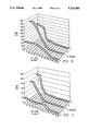
- FIG. 5 illustrates the relationship between the location of a sensor with respect to a convergence cone axis and the intensity of light received by the sensor.
- FIGS. 6-8 illustrates the relationship between the location of a sensor with respect to a section-to-lens axis and the intensity of light received.
- FIG. 9 illustrates the relationship between the spacing of the sensors and their field of view.
- FIG. 10 illustrates a housing for the receiver of FIG. 2.
- FIG. 1 illustrates an optical location system, comprised essentially of a receiver 11 and transmitter 12 and processing station 13, which are used to locate a target 14, to which transmitter 12 is attached.
- Target 14 moves within a defined location area 15.
- the sizes of receiver 11 and transmitter 12 are greatly exaggerated relative to the size of area 15.
- the location system is locating a work piece in a manufacturing plant.
- the target 14 is the work piece, such as a printed circuit board, which travels from one production station to another during the manufacturing process.
- the system of FIG. 1 is a two dimensional location system, in the sense that the location of target 14 is determined in terms of x and y coordinates of a plane parallel to the floor of area 15.
- area 15 is conceptualized as a grid of 36 sections, which in the example of FIG. 1 are identified by a letter A-F and an integer 1-6.
- Target 14 is shown in section (D,6).
- Transmitter 12 is attached to target 14. Each transmitter 12 transmits an omni-directional or near omni-directional optical signal at selected intervals.
- the signal typically includes an identifier so that if there is more than one target 14, it may be distinguished from other targets 14.
- transmitter 12 is an infrared source, which emits pulses representing digital information. However, transmitter 12 may also emit visible light or other radiation.
- Various devices for providing such an optical signal are known in the art of electro-optical devices.
- Receiver is a spherical lens and an array of optical sensors behind it. As explained below, each of these sensors is associated with one of the 36 sections of area 15.
- the lens directs emitted light to a sensor so that the position of the target may be determined by identifying the sensor that detects the light.
- Processing station 13 receives the output from receiver 11, which in its simplest form is a signal representing that a certain sensor of receiver 11 has detected incoming light from transmitter 12. In more complicated systems, a sequence of signals may be decoded to identify the particular target 14 being located. Processing station 13 accumulates data pertaining to each target 14 and its movement. The data that may be supplied to processing station 13 and its operation are described in U.S. Pat. No. 5,119,104, entitled "Location System Adapted for Use in Multipath Environments", to Heller.
- FIG. 2 illustrates the spherical lens 21 of receiver 11 and three of its sensors 23.
- lens 21 has a front side, which receives light from area 15, and a back side, from which this light emanates to sensors 23.
- Lens 21 is transparent, made from a plastic material such as acrylic.
- a feature of the invention is that many image qualities important to other optical systems are not important. Thus, the qualities of plastic that make it less than ideal for image applications, are immaterial to the invention. For example, color variations and resolution problem do not affect the energy gathering function of lens 21 if made from plastic.
- FIG. 2 also shows a single ray from a single point in each of three sections of area 15; a more complete illustration would have rays from a number of points in each section and would show such rays for each section of area 15. However, for simplicity of explanation, only one ray from the midpoint of sections (A,3), (B,3), and (C,3) is shown.
- Sensors 23 are conventional photosensitive devices, such as photodiodes.
- transmitter 12 is an infrared transmitter, thus sensors 23 detect infrared signals.
- Sensors 23 may be opto-electric devices that convert an optical input into an electrical signal for communication to processor 13. Or, sensors 23 may simply receive and communicate an optical signal, which is delivered to a transducer (not shown) for conversion to a signal that can be input to processor 13.
- sensors 23 are arranged in a three dimensional pattern behind lens 21. Although all sensors 23 are behind lens 21 with respect to area 15, they are not at the same distance, h, above lens 21. The value of h depends on the distance of the sensor 23 from its section. The spacing between any two sensors 23 also depends on the distance of each from its section.
- FIG. 3 is a plan view of the back side of spherical lens 21 and the sensors 23 above its surface. There are 36 sensors 23, one for each section of area 15. Each sensor 23 is labeled in terms of its associated section, i.e., the sensor 23 associated with section (B,3) is labelled (B,3).
- sensors 23 are arranged in three nearly circular rings.
- An inner ring has four sensors 23, an intermediate ring has twelve sensors 23, and an outer ring has twenty sensors 23.
- This pattern is related to the shape of area 15, which is a 6 ⁇ 6 square of sections.
- the scale of FIG. 3 indicates the relative position of each sensor 23 for a lens 21 that is one unit in radius.
- FIG. 3 maps each sensor 23 to its corresponding section of area 15, i.e., sensor 23(C,3) detects light from section (C,3).
- the inner ring of four sensors 23 corresponds to the inner square of sections, i.e., sections (C,3), (D,3), (C,4), and (D,4).
- the intermediate ring of twelve sensors 23 corresponds to sections (B,2)-(E,2), (E,3), (E,4), (E,5)-(B,5), (B,4) and (B,3).
- the outer ring of twenty sensors 23 corresponds to the outer sections of area 15.
- the three rings of sensors 23 are not equally spaced from each other. This spacing inversely corresponds to the distance of the sensors 23 in the ring to their associated sections. In other words, the rings are closer together as the distances of sensors 23 from their sections become greater. For example, because the sensors 23 of the inner ring are closer to their sections than are the sensors 23 of the outer ring, the spacing between the inner ring and the intermediate ring is greater than the spacing between the intermediate ring and the outer ring.
- FIG. 4 is another cross sectional view of lens 21, and in contrast to FIG. 2, shows a number of rays from a single point in one section. It illustrates how the rays from a point of any one section of area 15 form a "convergence cone" of light intensity behind lens 21.
- the rays incident at the front side of lens 21 converge toward the back of lens 21.
- P referred to herein as the convergence point. Due to spherical aberration, not all light converges, so that each convergence point receives approximately 80% of the total light from its section. However, this loss does not affect the operation of the invention.
- the location of convergence cones from points of an area is of known dimensions, for a lens 21 of a given size, can be calculated using known optical techniques. As explained below, for an area 15 that is divided into sections, these calculations are used to determine parameters such as the size of lens 21, its location over area 15, the size of sensors 23, and where to place the sensor 23 associated with each section.
- FIG. 4 also suggests, in two dimensions, how ray tracing can be used to locate a sensor 23 that will receive light from all points in a section of area 15.
- a single convergence cone of light from a section's midpoint could be calculated such that it is known to receive light from all points.
- rays may be traced from two or more points, resulting in overlapping convergence cones.
- a location can be determined that will receive light from all points in a section with a minimum of light from adjacent sections. For example, for a square section that is n ⁇ n feet, rays traced from four points, each located at a corner of an inner square, n/2 ⁇ n/2 feet, centered at the middle of the section, should result in four convergence cones. A sensor 23 that intersects all four cones will receive light from each point. The extent to which the cones overlap can be controlled to minimize light received from adjacent sections.
- a location for any sensor 23 with respect to lens 21 may be determined by means of ray tracing from at least one point in its corresponding section.
- the sensor 23 may be located at any height, h, so long as it receives light from both cones.
- a particular height, h can be determined such that each sensor 23 will receive not only light from different points in its section but light of the same intensity as that received by any other sensor 23.
- lens 21 provides a substantial amount of gain, depending on its size. This helps to avoid problems with ambient noise and permits the use of relatively small sensors.
- a typical lens 21 is 2 inches in diameter, with sensors 23 having a 0.1 inch square detection area.
- the sensor size and location, the lens size and location, and the section size and location are all parameters that can be adjusted to match the field of view of each sensor 23.
- FIG. 5 illustrates, for a given transmitter location, how the height of a sensor 23 above lens 21 affects the number of rays it receives from the emitting point as well as from "off-axis" points. It is assumed that 2000 rays were traced from a single emitting point in area 15, through the center of lens 21 to a sensor 23, resulting in a convergence cone having a section/sensor axis as in FIG. 2.
- the "off-axis" dimension represents a distance in inches from this axis to a "cone axis” that would be formed by convergence cones of light from other points near the emitting point.
- sensor 23 is a "point” sensor, in the sense that its receiving area is very small.
- FIGS. 6 and 7 illustrate the effect of varying the size of sensor 23.
- FIGS. 6 and 7 are similar to FIG. 5, except that the "off-axis" dimension represents the distance off-axis of a point in area 15 from the point at the end of the section/sensor axis. Again, h represents the height of the on-axis sensor 23. The ray hits decrease as the convergence cones of light from off-axis points intersect less and less of the sensor 23.
- the senor 23 has a half-width of 0.15 inch; in FIG. 7, this half-width is decreased to 0.05 inch.
- sensor 23 is either 0.3 or 0.1 inches square or in diameter.
- the radius of lens 21 is assumed to be 1 inch.
- the range of angles to lens 21 is approximately 25 degrees to 43 degrees, a difference of approximately 18 degrees. This requires an off-axis value of at least 9 degrees.
- the off-axis range of angles, and the corresponding range of possible sensor heights for each section can be similarly calculated.
- a further aspect of the invention is providing receiver 11 with an "isometric view" of area 15, in terms of detected light intensity.
- a section that is distant from lens 21, such as section (A,3) requires more light to be converged to its sensor 23 than does a closer section. This is accomplished by placing sensor 23 closer to its convergence point P, i.e., at a greater distance h from lens 21.
- FIG. 9, together with FIG. 3, illustrates how the different fields of view of sensors 23 having different distances, h, behind lens 21 can be matched to the perspective view of lens 21.
- FIG. 9 shows the perspective view of three sensors 23(D,4), 23(E,5) and 23(F,6) to their sections. The farther away sections appear smaller, and thus do not require as large a field of view as closer sections. To compensate for their distance from lens 21, sections that are farther away have sensors 23 with smaller fields of view but spaced more closely together.
- the spacing of sensors 23 from each other, as well as the height of each sensor 23 behind lens 21, are related to the distance of that sensor's corresponding section of area 15 from receiver 11. These parameters can be selected so that each sensor 23 "sees" approximately the same intensity from equally sized sections of area 15.
- the ray tracing techniques described herein need not be manually performed; computer programs can be developed to determine convergence locations for a spherical lens, given appropriate input data.
- sensor 23(A,3) detects light transmitted by transmitter 12 when target 14 is in any part of that section (A,3).
- Each sensor 23 is placed in a location that is determined by tracing convergence cones of rays from at least one point in the section to determine its location. The result is an array pattern such as that of FIG. 3.
- a maximum height, h is also determined. Assuming that receiver 11 is placed above the center of area 15, sensors 23(C,3), 23(C,4), 23(D,3), and 23(D,4) are closer to their corresponding sections than are any other sensor 23 to their corresponding sections.
- each sensor 23 receives light from a maximum area of its section with a minimum of light received from any other section. If it is desired that all sensors 23 receive the same intensity of light, the values of h are adjusted accordingly.
- a method of constructing a receiver 11 involves selecting an area 15 and choosing dimensions for each section.
- a lens 21 is chosen to have a size and location that will view all sections.
- To locate a sensor 23 for each section rays are traced from at least one point in each section.
- a sensor location is determined behind lens 21, at a height within a certain range, where the sensor 23 will receive light from a maximum area of the section and a minimum of light from other sections. In this manner, each sensor 23 is located so that if transmitter 13 is anywhere in area 15, at least one sensor 23 will detect its emitted light. If desired, a unique height above lens 21 is determined for each sensor 23, such that it will receive light of a certain desired intensity.
- sensor patterns different from that of FIG. 2 would be used.
- the same general concept applies in that ray tracing can be used to relate the size and location of sections to the size and location of sensors 23.
- sensors 23 associated with sections that are farther away from lens 21 would have narrower fields of view and would be more densely spaced than sensors 23 associated with closer sections.
- the spacing between sensors 23 might be made the same.
- FIG. 10 illustrates a housing 81 for positioning sensors 23 above lens 21.
- Connectors 82 one associated with each sensor 23 are contained within housing 81.
- Each connector 82 extends from housing 81 a predetermined distance above lens 21, such that each sensor 23 is at a predetermined height, h.
- a sensor 23 is placed at the end of each tube 82, such that the signal generated when light is detected travels through connector 82 to processing station 13. If sensors 23 are photoelectric devices, connectors 82 transmit their electrical output to a decoder in housing 81 an appropriate signal identifying the sensor 23 is communicated to processor 13.
- Connectors 82 could also be light tubes for communicating an optical output to an appropriate transducer. In this case, each sensor 23 would be a simple light receiver, perhaps with an amplification means.
Abstract
Description
Claims (22)
Priority Applications (1)
| Application Number | Priority Date | Filing Date | Title |
|---|---|---|---|
| US07/969,753 US5276496A (en) | 1992-10-30 | 1992-10-30 | Optical receiver for area location system |
Applications Claiming Priority (1)
| Application Number | Priority Date | Filing Date | Title |
|---|---|---|---|
| US07/969,753 US5276496A (en) | 1992-10-30 | 1992-10-30 | Optical receiver for area location system |
Publications (1)
| Publication Number | Publication Date |
|---|---|
| US5276496A true US5276496A (en) | 1994-01-04 |
Family
ID=25515946
Family Applications (1)
| Application Number | Title | Priority Date | Filing Date |
|---|---|---|---|
| US07/969,753 Expired - Lifetime US5276496A (en) | 1992-10-30 | 1992-10-30 | Optical receiver for area location system |
Country Status (1)
| Country | Link |
|---|---|
| US (1) | US5276496A (en) |
Cited By (40)
| Publication number | Priority date | Publication date | Assignee | Title |
|---|---|---|---|---|
| US5428215A (en) * | 1994-05-27 | 1995-06-27 | Her Majesty The Queen In Right Of Canada, As Represented By Minister Of National Defence Of Her Majesty's Canadian Government | Digital high angular resolution laser irradiation detector (HARLID) |
| US5742238A (en) * | 1995-09-01 | 1998-04-21 | Emtrak, Inc. | System for communication between a central controller and items in a factory using infrared light |
| US6104295A (en) * | 1998-07-20 | 2000-08-15 | Versus Technology, Inc. | Electronic band tag and method of storing ID information therein |
| US6138058A (en) * | 1998-01-06 | 2000-10-24 | Jenoptik Infab, Inc. | Method for electronically tracking containers to avoid misprocessing of contents |
| US6150921A (en) * | 1996-10-17 | 2000-11-21 | Pinpoint Corporation | Article tracking system |
| US6154139A (en) * | 1998-04-21 | 2000-11-28 | Versus Technology | Method and system for locating subjects within a tracking environment |
| US6222440B1 (en) | 1998-02-23 | 2001-04-24 | Freshloc Technologies, Inc. | Location, identification and telemetry system using strobed signals at predetermined intervals |
| US6373389B1 (en) | 2000-04-21 | 2002-04-16 | Usm Systems, Ltd. | Event driven information system |
| US20020145534A1 (en) * | 2001-03-09 | 2002-10-10 | Sentinel Wireless, Llc | System and method for performing object association using a location tracking system |
| US6490801B1 (en) * | 1999-11-19 | 2002-12-10 | Centre For Research In Earth And Space Technology | Sun sensors using multi-pinhole overlays |
| US6498585B2 (en) * | 2000-08-24 | 2002-12-24 | Fast Location.Net, Llc | Method and apparatus for rapidly estimating the doppler-error and other receiver frequency errors of global positioning system satellite signals weakened by obstructions in the signal path |
| US6515620B1 (en) | 2001-07-18 | 2003-02-04 | Fast Location.Net, Llc | Method and system for processing positioning signals in a geometric mode |
| US6529160B2 (en) | 2001-07-18 | 2003-03-04 | Fast Location.Net, Llc | Method and system for determining carrier frequency offsets for positioning signals |
| US20030148812A1 (en) * | 2002-02-01 | 2003-08-07 | Paulsen Craig A. | Gaming system and gaming method |
| US6628234B2 (en) | 2001-07-18 | 2003-09-30 | Fast Location.Net, Llc | Method and system for processing positioning signals in a stand-alone mode |
| US20040023709A1 (en) * | 2002-08-05 | 2004-02-05 | Nicole Beaulieu | Gaming apparatus and gaming method |
| US20040041728A1 (en) * | 2001-07-18 | 2004-03-04 | Bromley Patrick G. | Method and system for processing positioning signals based on predetermined message data segment |
| US6753781B2 (en) | 1999-05-19 | 2004-06-22 | Elpas North America, Inc. | Infant and parent matching and security system and method of matching infant and parent |
| US20040183682A1 (en) * | 2003-03-21 | 2004-09-23 | Versus Technology, Inc. | Methods and systems for locating subjects and providing event notification within a tracking environment and badge for use therein |
| US6812824B1 (en) | 1996-10-17 | 2004-11-02 | Rf Technologies, Inc. | Method and apparatus combining a tracking system and a wireless communication system |
| US20050043072A1 (en) * | 2002-02-06 | 2005-02-24 | Igt | Control and configuration of gaming machines based on gaming machine location |
| US20060261951A1 (en) * | 2005-04-26 | 2006-11-23 | Rf Code, Inc. | RFID systems and methods employing infrared localization |
| US20080316462A1 (en) * | 2007-04-20 | 2008-12-25 | Riel Ryan D | Curved sensor array apparatus and methods |
| US20090284347A1 (en) * | 2008-05-15 | 2009-11-19 | International Business Machines Corporation | Identity verification badge and method for utilizing same in a security system |
| US20110121962A1 (en) * | 2009-11-23 | 2011-05-26 | Versus Technology, Inc. | Real-time method and system for locating a mobile object or person in a tracking environment while conserving electrical energy in a battery-operated tracking tag associated with the object or person |
| US20110125524A1 (en) * | 2009-11-20 | 2011-05-26 | Versus Technology, Inc. | Context-aware method and system for facilitating the delivery of healthcare to patients within a clinical environment monitored by real-time locating apparatus |
| US20110121974A1 (en) * | 2009-11-20 | 2011-05-26 | Versus Technology, Inc. | Real-time method and system for monitoring hygiene compliance within a tracking environment |
| US20110125513A1 (en) * | 2009-11-20 | 2011-05-26 | Versus Technology, Inc. | Real-time method and system for controlling healthcare delivery processes within a clinical environment |
| US8310364B2 (en) | 2010-07-28 | 2012-11-13 | Versus Technology, Inc. | Real-time method and system for determining and validating location of a relocated mobile object or person in a tracking environment |
| US8514071B2 (en) | 2010-07-28 | 2013-08-20 | Versus Technology, Inc. | Real-time method and system for locating a mobile object or person in a tracking environment |
| US8742929B2 (en) | 2002-07-09 | 2014-06-03 | Automated Tracking Solutions, Llc | Method and apparatus for tracking objects and people |
| US9052374B2 (en) | 2001-07-18 | 2015-06-09 | Fast Location.Net, Llc | Method and system for processing positioning signals based on predetermined message data segment |
| US9349267B2 (en) | 1999-10-29 | 2016-05-24 | Hill-Rom Services, Inc. | Hygiene monitoring system |
| US9773403B2 (en) | 2015-07-28 | 2017-09-26 | Hill-Rom Services, Inc. | Hygiene compliance system |
| US9830424B2 (en) | 2013-09-18 | 2017-11-28 | Hill-Rom Services, Inc. | Bed/room/patient association systems and methods |
| US10260844B2 (en) | 2008-03-17 | 2019-04-16 | Israel Aerospace Industries, Ltd. | Method for performing exo-atmospheric missile's interception trial |
| US10495510B2 (en) | 2016-07-03 | 2019-12-03 | Elta Systems Ltd. | Systems and methods for flash localization using at least two photodiodes |
| US10607471B2 (en) | 2015-10-06 | 2020-03-31 | Hill-Rom Services, Inc. | Hand hygiene monitoring system with customizable thresholds |
| US10731977B1 (en) * | 2018-08-03 | 2020-08-04 | Rockwell Collins, Inc. | Automated zone accuracy for lever-arm and euler-angle alignment |
| US11911325B2 (en) | 2019-02-26 | 2024-02-27 | Hill-Rom Services, Inc. | Bed interface for manual location |
Citations (4)
| Publication number | Priority date | Publication date | Assignee | Title |
|---|---|---|---|---|
| US4193689A (en) * | 1977-07-29 | 1980-03-18 | Thomson-Csf | Arrangement for locating radiaring sources |
| US4806747A (en) * | 1988-02-19 | 1989-02-21 | The Perkin-Elmer Corporation | Optical direction of arrival sensor with cylindrical lens |
| US5047776A (en) * | 1990-06-27 | 1991-09-10 | Hughes Aircraft Company | Multibeam optical and electromagnetic hemispherical/spherical sensor |
| US5076687A (en) * | 1990-08-28 | 1991-12-31 | Massachusetts Institute Of Technology | Optical ranging apparatus |
-
1992
- 1992-10-30 US US07/969,753 patent/US5276496A/en not_active Expired - Lifetime
Patent Citations (4)
| Publication number | Priority date | Publication date | Assignee | Title |
|---|---|---|---|---|
| US4193689A (en) * | 1977-07-29 | 1980-03-18 | Thomson-Csf | Arrangement for locating radiaring sources |
| US4806747A (en) * | 1988-02-19 | 1989-02-21 | The Perkin-Elmer Corporation | Optical direction of arrival sensor with cylindrical lens |
| US5047776A (en) * | 1990-06-27 | 1991-09-10 | Hughes Aircraft Company | Multibeam optical and electromagnetic hemispherical/spherical sensor |
| US5076687A (en) * | 1990-08-28 | 1991-12-31 | Massachusetts Institute Of Technology | Optical ranging apparatus |
Cited By (82)
| Publication number | Priority date | Publication date | Assignee | Title |
|---|---|---|---|---|
| US5428215A (en) * | 1994-05-27 | 1995-06-27 | Her Majesty The Queen In Right Of Canada, As Represented By Minister Of National Defence Of Her Majesty's Canadian Government | Digital high angular resolution laser irradiation detector (HARLID) |
| US5742238A (en) * | 1995-09-01 | 1998-04-21 | Emtrak, Inc. | System for communication between a central controller and items in a factory using infrared light |
| US6812824B1 (en) | 1996-10-17 | 2004-11-02 | Rf Technologies, Inc. | Method and apparatus combining a tracking system and a wireless communication system |
| US6150921A (en) * | 1996-10-17 | 2000-11-21 | Pinpoint Corporation | Article tracking system |
| US6483427B1 (en) | 1996-10-17 | 2002-11-19 | Rf Technologies, Inc. | Article tracking system |
| US6138058A (en) * | 1998-01-06 | 2000-10-24 | Jenoptik Infab, Inc. | Method for electronically tracking containers to avoid misprocessing of contents |
| US6222440B1 (en) | 1998-02-23 | 2001-04-24 | Freshloc Technologies, Inc. | Location, identification and telemetry system using strobed signals at predetermined intervals |
| US6154139A (en) * | 1998-04-21 | 2000-11-28 | Versus Technology | Method and system for locating subjects within a tracking environment |
| US6104295A (en) * | 1998-07-20 | 2000-08-15 | Versus Technology, Inc. | Electronic band tag and method of storing ID information therein |
| US6753781B2 (en) | 1999-05-19 | 2004-06-22 | Elpas North America, Inc. | Infant and parent matching and security system and method of matching infant and parent |
| US9911312B2 (en) | 1999-10-29 | 2018-03-06 | Hill-Rom Services, Inc. | Hygiene monitoring system |
| US9349267B2 (en) | 1999-10-29 | 2016-05-24 | Hill-Rom Services, Inc. | Hygiene monitoring system |
| US9396638B2 (en) | 1999-10-29 | 2016-07-19 | Hill-Rom Services, Inc. | Hygiene monitoring system |
| US9715817B2 (en) | 1999-10-29 | 2017-07-25 | Hill-Rom Services, Inc. | Hygiene monitoring system |
| US6490801B1 (en) * | 1999-11-19 | 2002-12-10 | Centre For Research In Earth And Space Technology | Sun sensors using multi-pinhole overlays |
| US6373389B1 (en) | 2000-04-21 | 2002-04-16 | Usm Systems, Ltd. | Event driven information system |
| US6498585B2 (en) * | 2000-08-24 | 2002-12-24 | Fast Location.Net, Llc | Method and apparatus for rapidly estimating the doppler-error and other receiver frequency errors of global positioning system satellite signals weakened by obstructions in the signal path |
| US6650285B2 (en) | 2000-08-24 | 2003-11-18 | Fast Location.Net, Llc | Method and apparatus for rapidly estimating the doppler-error and other receiver frequency errors of global positioning system satellite signals weakened by obstructions in the signal path |
| US8190730B2 (en) | 2001-03-09 | 2012-05-29 | Consortium P, Inc. | Location system and methods |
| US20020145534A1 (en) * | 2001-03-09 | 2002-10-10 | Sentinel Wireless, Llc | System and method for performing object association using a location tracking system |
| US7099895B2 (en) | 2001-03-09 | 2006-08-29 | Radianse, Inc. | System and method for performing object association using a location tracking system |
| US20020165731A1 (en) * | 2001-03-09 | 2002-11-07 | Sentinel Wireless, Llc | System and method for performing object association at a tradeshow using a location tracking system |
| US7057553B2 (en) | 2001-07-18 | 2006-06-06 | Fast Location.Net, Llc | Method and system for processing positioning signals in a stand-alone mode |
| US9052374B2 (en) | 2001-07-18 | 2015-06-09 | Fast Location.Net, Llc | Method and system for processing positioning signals based on predetermined message data segment |
| US6774841B2 (en) | 2001-07-18 | 2004-08-10 | Fast Location.Net, Llc | Method and system for processing positioning signals in a geometric mode |
| US20050035904A1 (en) * | 2001-07-18 | 2005-02-17 | Fast Location.Net, Llc, A Texas Corporation | Method and system for processing positioning signals in a stand-alone mode |
| US20100090894A1 (en) * | 2001-07-18 | 2010-04-15 | Fast Location Net, Llc | Method and System for Processing Positioning Signals Based on Predetermined Message Data Segment |
| US7633439B2 (en) | 2001-07-18 | 2009-12-15 | Fast Location.Net, Llc | Method and system for processing positioning signals based on predetermined message data segment |
| US6882309B2 (en) | 2001-07-18 | 2005-04-19 | Fast Location. Net, Llc | Method and system for processing positioning signals based on predetermined message data segment |
| US8102312B2 (en) | 2001-07-18 | 2012-01-24 | Fast Location.Net, Llc | Method and system for processing positioning signals based on predetermined message data segment |
| US6515620B1 (en) | 2001-07-18 | 2003-02-04 | Fast Location.Net, Llc | Method and system for processing positioning signals in a geometric mode |
| US20040041728A1 (en) * | 2001-07-18 | 2004-03-04 | Bromley Patrick G. | Method and system for processing positioning signals based on predetermined message data segment |
| US7154437B2 (en) | 2001-07-18 | 2006-12-26 | Fast Location.Net, Llc | Method and system for processing positioning signals based on predetermined message data segment |
| US6628234B2 (en) | 2001-07-18 | 2003-09-30 | Fast Location.Net, Llc | Method and system for processing positioning signals in a stand-alone mode |
| US20070120735A1 (en) * | 2001-07-18 | 2007-05-31 | Fast Location.Net, Llc | Method and System for Processing Positioning Signals Based on Predetermined Message Data Segment |
| US6529160B2 (en) | 2001-07-18 | 2003-03-04 | Fast Location.Net, Llc | Method and system for determining carrier frequency offsets for positioning signals |
| US7874919B2 (en) | 2002-02-01 | 2011-01-25 | Igt | Gaming system and gaming method |
| US20030148812A1 (en) * | 2002-02-01 | 2003-08-07 | Paulsen Craig A. | Gaming system and gaming method |
| US20050059485A1 (en) * | 2002-02-01 | 2005-03-17 | Igt, A Nevada Corporation | Gaming system and gaming method |
| US20080051198A1 (en) * | 2002-02-06 | 2008-02-28 | Igt | Configuration of gaming machines based on gaming machine location |
| US8870657B2 (en) | 2002-02-06 | 2014-10-28 | Igt | Configuration of gaming machines based on gaming machine location |
| US7316619B2 (en) | 2002-02-06 | 2008-01-08 | Igt | Control and configuration of gaming machines based on gaming machine location |
| US8235816B2 (en) | 2002-02-06 | 2012-08-07 | Igt | Configuration of gaming machines based on gaming machine location |
| US20050043072A1 (en) * | 2002-02-06 | 2005-02-24 | Igt | Control and configuration of gaming machines based on gaming machine location |
| US8842013B2 (en) | 2002-07-09 | 2014-09-23 | Automated Tracking Solutions, Llc | Method and apparatus for tracking objects and people |
| US10152620B2 (en) | 2002-07-09 | 2018-12-11 | Automated Tracking Solutions, Llc | Method and apparatus for tracking objects and people |
| US8866615B2 (en) | 2002-07-09 | 2014-10-21 | Automated Tracking Solutions, Llc | Method and apparatus for tracking objects and people |
| US10496859B2 (en) | 2002-07-09 | 2019-12-03 | Automated Tracking Solutions, Llc | Method and apparatus for tracking objects and people |
| US8896449B2 (en) | 2002-07-09 | 2014-11-25 | Automated Tracking Solutions, Llc | Method and apparatus for tracking objects and people |
| US9619679B2 (en) | 2002-07-09 | 2017-04-11 | Automated Tracking Solutions, Llc | Method and apparatus for tracking objects and people |
| US8742929B2 (en) | 2002-07-09 | 2014-06-03 | Automated Tracking Solutions, Llc | Method and apparatus for tracking objects and people |
| US7169052B2 (en) | 2002-08-05 | 2007-01-30 | Igt | Personalized gaming apparatus and gaming method |
| US8187073B2 (en) | 2002-08-05 | 2012-05-29 | Igt | Personalized gaming apparatus and gaming method |
| US20040023709A1 (en) * | 2002-08-05 | 2004-02-05 | Nicole Beaulieu | Gaming apparatus and gaming method |
| US6838992B2 (en) | 2003-03-21 | 2005-01-04 | Versus Technology, Inc. | Methods and systems for locating subjects and providing event notification within a tracking environment and badge for use therein |
| US20040183682A1 (en) * | 2003-03-21 | 2004-09-23 | Versus Technology, Inc. | Methods and systems for locating subjects and providing event notification within a tracking environment and badge for use therein |
| US20060261951A1 (en) * | 2005-04-26 | 2006-11-23 | Rf Code, Inc. | RFID systems and methods employing infrared localization |
| US7486189B2 (en) | 2005-04-26 | 2009-02-03 | Rf Code, Inc | RFID systems and methods employing infrared localization |
| US7619754B2 (en) | 2007-04-20 | 2009-11-17 | Riel Ryan D | Curved sensor array apparatus and methods |
| WO2009017524A3 (en) * | 2007-04-20 | 2009-04-09 | Lucid Dimensions Llc | Curved sensor array apparatus and methods |
| US20080316462A1 (en) * | 2007-04-20 | 2008-12-25 | Riel Ryan D | Curved sensor array apparatus and methods |
| US10260844B2 (en) | 2008-03-17 | 2019-04-16 | Israel Aerospace Industries, Ltd. | Method for performing exo-atmospheric missile's interception trial |
| US20090284347A1 (en) * | 2008-05-15 | 2009-11-19 | International Business Machines Corporation | Identity verification badge and method for utilizing same in a security system |
| US8390428B2 (en) | 2008-05-15 | 2013-03-05 | International Business Machines Corporation | Identity verification badge and security system |
| US11211154B2 (en) | 2009-11-20 | 2021-12-28 | Midmark RTLS Solutions Inc. | Context-aware method and system for facilitating the delivery of healthcare to patients within a clinical environment monitored by real-time locating apparatus |
| US20110125513A1 (en) * | 2009-11-20 | 2011-05-26 | Versus Technology, Inc. | Real-time method and system for controlling healthcare delivery processes within a clinical environment |
| US20110121974A1 (en) * | 2009-11-20 | 2011-05-26 | Versus Technology, Inc. | Real-time method and system for monitoring hygiene compliance within a tracking environment |
| US20110125524A1 (en) * | 2009-11-20 | 2011-05-26 | Versus Technology, Inc. | Context-aware method and system for facilitating the delivery of healthcare to patients within a clinical environment monitored by real-time locating apparatus |
| US9922167B2 (en) | 2009-11-20 | 2018-03-20 | Versus Technology, Inc. | Context-aware method and system for facilitating the delivery of healthcare to patients within a clinical environment monitored by real-time locating apparatus |
| US20110121962A1 (en) * | 2009-11-23 | 2011-05-26 | Versus Technology, Inc. | Real-time method and system for locating a mobile object or person in a tracking environment while conserving electrical energy in a battery-operated tracking tag associated with the object or person |
| US8416072B2 (en) | 2009-11-23 | 2013-04-09 | Versus Technology, Inc. | Real-time method and system for locating a mobile object or person in a tracking environment while conserving electrical energy in a battery-operated tracking tag associated with the object or person |
| WO2011062659A1 (en) | 2009-11-23 | 2011-05-26 | Versus Technology, Inc. | Real-time method and system for locating a mobile object or person while conserving electrical energy |
| US8310364B2 (en) | 2010-07-28 | 2012-11-13 | Versus Technology, Inc. | Real-time method and system for determining and validating location of a relocated mobile object or person in a tracking environment |
| US8514071B2 (en) | 2010-07-28 | 2013-08-20 | Versus Technology, Inc. | Real-time method and system for locating a mobile object or person in a tracking environment |
| US9830424B2 (en) | 2013-09-18 | 2017-11-28 | Hill-Rom Services, Inc. | Bed/room/patient association systems and methods |
| US11011267B2 (en) | 2013-09-18 | 2021-05-18 | Hill-Rom Services, Inc. | Bed/room/patient association systems and methods |
| US9959743B2 (en) | 2015-07-28 | 2018-05-01 | Hill-Rom Services, Inc. | Hygiene compliance system |
| US9773403B2 (en) | 2015-07-28 | 2017-09-26 | Hill-Rom Services, Inc. | Hygiene compliance system |
| US10607471B2 (en) | 2015-10-06 | 2020-03-31 | Hill-Rom Services, Inc. | Hand hygiene monitoring system with customizable thresholds |
| US10495510B2 (en) | 2016-07-03 | 2019-12-03 | Elta Systems Ltd. | Systems and methods for flash localization using at least two photodiodes |
| US10731977B1 (en) * | 2018-08-03 | 2020-08-04 | Rockwell Collins, Inc. | Automated zone accuracy for lever-arm and euler-angle alignment |
| US11911325B2 (en) | 2019-02-26 | 2024-02-27 | Hill-Rom Services, Inc. | Bed interface for manual location |
Similar Documents
| Publication | Publication Date | Title |
|---|---|---|
| US5276496A (en) | Optical receiver for area location system | |
| US5355222A (en) | Optical receiver for area location system | |
| US4420261A (en) | Optical position location apparatus | |
| US6424442B1 (en) | Optical transmitter and transceiver module for wireless data transmission | |
| US4936683A (en) | Optical tablet construction | |
| KR20010014970A (en) | Optical unit for detecting object and coordinate input apparatus using the same | |
| US6266136B1 (en) | Position tracking system | |
| US4893025A (en) | Distributed proximity sensor system having embedded light emitters and detectors | |
| CN101167042A (en) | Light emitting stylus and user input device using same | |
| WO1998044316A1 (en) | Adjustable area coordinate position data-capture system | |
| GB2131544A (en) | Optical position location apparatus | |
| US10998972B2 (en) | Receiver, method, terminal device, light transmissive structure and system for visible light communication | |
| CN1105308C (en) | Remote position sensing apparatus and method | |
| KR100905382B1 (en) | Method for processing optical signals in a computer mouse | |
| US5587580A (en) | Optoelectronic sensor for measuring the intensity and the direction of incidence of a light beam | |
| US5774247A (en) | Optical signal transceiver for use with diffusely transmitted optical radiation | |
| US10209799B2 (en) | Touch display system and touch operation device | |
| WO2018101001A1 (en) | Infrared sensor | |
| EP0849896B1 (en) | Transceiver module for wireless data transmission | |
| EP1218769A1 (en) | Optical angle sensor for use in a position and/or attitude determination system | |
| WO2018101002A1 (en) | Infrared detection device | |
| GB2375249A (en) | Indirect freespace optical communications | |
| WO1997027450A1 (en) | A position tracking system | |
| RU2108617C1 (en) | Method and device for remote input of information into controlled entity | |
| RU2096821C1 (en) | Device for information input into controlled object |
Legal Events
| Date | Code | Title | Description |
|---|---|---|---|
| AS | Assignment |
Owner name: PRECISION TRACKING FM, INC., TEXAS Free format text: ASSIGNMENT OF ASSIGNORS INTEREST.;ASSIGNORS:HELLER, ALAN C.;MCNAMARA, ALBERT C., JR.;REEL/FRAME:006310/0343;SIGNING DATES FROM 19921019 TO 19921021 |
|
| STCF | Information on status: patent grant |
Free format text: PATENTED CASE |
|
| FPAY | Fee payment |
Year of fee payment: 4 |
|
| AS | Assignment |
Owner name: VERSUS TECHNOLOGY, INC. (A DELAWARE CORP.), MICHIG Free format text: LICENSE;ASSIGNOR:HELLER, ALAN C., PRESIDENT, PRECISION TRACKING F.M. INC., A TEXAS CORP.;REEL/FRAME:008628/0126 Effective date: 19970708 |
|
| AS | Assignment |
Owner name: DDJK PARTNERSHIP, NEW YORK Free format text: SECURED CONVERTIBLE DEBENTURE;ASSIGNOR:VERSUS TECHNOLOGY, INC.;REEL/FRAME:010197/0696 Effective date: 19990531 Owner name: SMITH, BARNEY, CUSTODIAN FOR IRA OF JOHN ARTHUR MA Free format text: SECURED CONVERTIBLE DEBENTURE;ASSIGNOR:VERSUS TECHNOLOGY, INC.;REEL/FRAME:010197/0696 Effective date: 19990531 Owner name: MR. SAMUEL DAVIS, NEW YORK Free format text: SECURED CONVERTIBLE DEBENTURE;ASSIGNOR:VERSUS TECHNOLOGY, INC.;REEL/FRAME:010197/0696 Effective date: 19990531 Owner name: GLEN ARDEN ASSOCIATES, PENNSYLVANIA Free format text: SECURED CONVERTIBLE DEBENTURE;ASSIGNOR:VERSUS TECHNOLOGY, INC.;REEL/FRAME:010197/0696 Effective date: 19990531 Owner name: MALCHO, CHARLES M., MICHIGAN Free format text: SECURED CONVERTIBLE DEBENTURE;ASSIGNOR:VERSUS TECHNOLOGY, INC.;REEL/FRAME:010197/0696 Effective date: 19990531 Owner name: GREENAPPLE, LAWRENCE, NEW YORK Free format text: SECURED CONVERTIBLE DEBENTURE;ASSIGNOR:VERSUS TECHNOLOGY, INC.;REEL/FRAME:010197/0696 Effective date: 19990531 Owner name: SALLY A. SORENSON REVOCABLE TRUST, OHIO Free format text: SECURED CONVERTIBLE DEBENTURE;ASSIGNOR:VERSUS TECHNOLOGY, INC.;REEL/FRAME:010197/0696 Effective date: 19990531 Owner name: LAMOTTE, KENNETH J., MICHIGAN Free format text: SECURED CONVERTIBLE DEBENTURE;ASSIGNOR:VERSUS TECHNOLOGY, INC.;REEL/FRAME:010197/0696 Effective date: 19990531 Owner name: WALTER C. WOJACK REVOCABLE TRUST, OHIO Free format text: SECURED CONVERTIBLE DEBENTURE;ASSIGNOR:VERSUS TECHNOLOGY, INC.;REEL/FRAME:010197/0696 Effective date: 19990531 Owner name: GIII, LLC, MICHIGAN Free format text: SECURED CONVERTIBLE DEBENTURE;ASSIGNOR:VERSUS TECHNOLOGY, INC.;REEL/FRAME:010197/0696 Effective date: 19990531 Owner name: COX, JR., GILBERT C., TRUSTEE, MICHIGAN Free format text: SECURED CONVERTIBLE DEBENTURE;ASSIGNOR:VERSUS TECHNOLOGY, INC.;REEL/FRAME:010197/0696 Effective date: 19990531 Owner name: MAY, RICHARD H., TRUSTEE, MICHIGAN Free format text: SECURED CONVERTIBLE DEBENTURE;ASSIGNOR:VERSUS TECHNOLOGY, INC.;REEL/FRAME:010197/0696 Effective date: 19990531 Owner name: MAY, SIMPSON & STROTE, MICHIGAN Free format text: SECURED CONVERTIBLE DEBENTURE;ASSIGNOR:VERSUS TECHNOLOGY, INC.;REEL/FRAME:010197/0696 Effective date: 19990531 Owner name: SALZER, RICHARD J., ILLINOIS Free format text: SECURED CONVERTIBLE DEBENTURE;ASSIGNOR:VERSUS TECHNOLOGY, INC.;REEL/FRAME:010197/0696 Effective date: 19990531 Owner name: C.L. RIECKHOFF COMPANY 401 (K) PLAN, MICHIGAN Free format text: SECURED CONVERTIBLE DEBENTURE;ASSIGNOR:VERSUS TECHNOLOGY, INC.;REEL/FRAME:010197/0696 Effective date: 19990531 |
|
| AS | Assignment |
Owner name: FRESHLOC TECHNOLOGIES, INC., TEXAS Free format text: ASSIGNMENT OF ASSIGNORS INTEREST;ASSIGNOR:SERVICE ID, INC.;REEL/FRAME:010742/0329 Effective date: 20000309 |
|
| FEPP | Fee payment procedure |
Free format text: PAT HOLDER CLAIMS SMALL ENTITY STATUS - SMALL BUSINESS (ORIGINAL EVENT CODE: SM02); ENTITY STATUS OF PATENT OWNER: SMALL ENTITY |
|
| FPAY | Fee payment |
Year of fee payment: 8 |
|
| FPAY | Fee payment |
Year of fee payment: 12 |
|
| SULP | Surcharge for late payment |
Year of fee payment: 11 |
|
| REMI | Maintenance fee reminder mailed | ||
| AS | Assignment |
Owner name: VERSUS TECHNOLOGY, INC., MICHIGAN Free format text: RELEASE BY SECURED PARTY;ASSIGNORS:GLEN ARDEN ASSOCIATES;MALCHO, CHARLES M.;SALZER, RICHARD J.;AND OTHERS;REEL/FRAME:037900/0049 Effective date: 20160218 |