US5267587A - Utilities shutoff system - Google Patents
Utilities shutoff system Download PDFInfo
- Publication number
- US5267587A US5267587A US07/864,677 US86467792A US5267587A US 5267587 A US5267587 A US 5267587A US 86467792 A US86467792 A US 86467792A US 5267587 A US5267587 A US 5267587A
- Authority
- US
- United States
- Prior art keywords
- water
- supply line
- time delay
- valve
- flow
- Prior art date
- Legal status (The legal status is an assumption and is not a legal conclusion. Google has not performed a legal analysis and makes no representation as to the accuracy of the status listed.)
- Expired - Lifetime
Links
Images


Classifications
-
- G—PHYSICS
- G01—MEASURING; TESTING
- G01M—TESTING STATIC OR DYNAMIC BALANCE OF MACHINES OR STRUCTURES; TESTING OF STRUCTURES OR APPARATUS, NOT OTHERWISE PROVIDED FOR
- G01M3/00—Investigating fluid-tightness of structures
- G01M3/02—Investigating fluid-tightness of structures by using fluid or vacuum
- G01M3/26—Investigating fluid-tightness of structures by using fluid or vacuum by measuring rate of loss or gain of fluid, e.g. by pressure-responsive devices, by flow detectors
- G01M3/28—Investigating fluid-tightness of structures by using fluid or vacuum by measuring rate of loss or gain of fluid, e.g. by pressure-responsive devices, by flow detectors for pipes, cables or tubes; for pipe joints or seals; for valves ; for welds
- G01M3/2807—Investigating fluid-tightness of structures by using fluid or vacuum by measuring rate of loss or gain of fluid, e.g. by pressure-responsive devices, by flow detectors for pipes, cables or tubes; for pipe joints or seals; for valves ; for welds for pipes
- G01M3/2815—Investigating fluid-tightness of structures by using fluid or vacuum by measuring rate of loss or gain of fluid, e.g. by pressure-responsive devices, by flow detectors for pipes, cables or tubes; for pipe joints or seals; for valves ; for welds for pipes using pressure measurements
-
- E—FIXED CONSTRUCTIONS
- E03—WATER SUPPLY; SEWERAGE
- E03B—INSTALLATIONS OR METHODS FOR OBTAINING, COLLECTING, OR DISTRIBUTING WATER
- E03B7/00—Water main or service pipe systems
- E03B7/07—Arrangement of devices, e.g. filters, flow controls, measuring devices, siphons, valves, in the pipe systems
- E03B7/071—Arrangement of safety devices in domestic pipe systems, e.g. devices for automatic shut-off
-
- E—FIXED CONSTRUCTIONS
- E03—WATER SUPPLY; SEWERAGE
- E03D—WATER-CLOSETS OR URINALS WITH FLUSHING DEVICES; FLUSHING VALVES THEREFOR
- E03D1/00—Water flushing devices with cisterns ; Setting up a range of flushing devices or water-closets; Combinations of several flushing devices
-
- Y—GENERAL TAGGING OF NEW TECHNOLOGICAL DEVELOPMENTS; GENERAL TAGGING OF CROSS-SECTIONAL TECHNOLOGIES SPANNING OVER SEVERAL SECTIONS OF THE IPC; TECHNICAL SUBJECTS COVERED BY FORMER USPC CROSS-REFERENCE ART COLLECTIONS [XRACs] AND DIGESTS
- Y02—TECHNOLOGIES OR APPLICATIONS FOR MITIGATION OR ADAPTATION AGAINST CLIMATE CHANGE
- Y02A—TECHNOLOGIES FOR ADAPTATION TO CLIMATE CHANGE
- Y02A20/00—Water conservation; Efficient water supply; Efficient water use
- Y02A20/15—Leakage reduction or detection in water storage or distribution
-
- Y—GENERAL TAGGING OF NEW TECHNOLOGICAL DEVELOPMENTS; GENERAL TAGGING OF CROSS-SECTIONAL TECHNOLOGIES SPANNING OVER SEVERAL SECTIONS OF THE IPC; TECHNICAL SUBJECTS COVERED BY FORMER USPC CROSS-REFERENCE ART COLLECTIONS [XRACs] AND DIGESTS
- Y10—TECHNICAL SUBJECTS COVERED BY FORMER USPC
- Y10T—TECHNICAL SUBJECTS COVERED BY FORMER US CLASSIFICATION
- Y10T137/00—Fluid handling
- Y10T137/7722—Line condition change responsive valves
- Y10T137/7758—Pilot or servo controlled
- Y10T137/7759—Responsive to change in rate of fluid flow
-
- Y—GENERAL TAGGING OF NEW TECHNOLOGICAL DEVELOPMENTS; GENERAL TAGGING OF CROSS-SECTIONAL TECHNOLOGIES SPANNING OVER SEVERAL SECTIONS OF THE IPC; TECHNICAL SUBJECTS COVERED BY FORMER USPC CROSS-REFERENCE ART COLLECTIONS [XRACs] AND DIGESTS
- Y10—TECHNICAL SUBJECTS COVERED BY FORMER USPC
- Y10T—TECHNICAL SUBJECTS COVERED BY FORMER US CLASSIFICATION
- Y10T137/00—Fluid handling
- Y10T137/7722—Line condition change responsive valves
- Y10T137/7758—Pilot or servo controlled
- Y10T137/7761—Electrically actuated valve
-
- Y—GENERAL TAGGING OF NEW TECHNOLOGICAL DEVELOPMENTS; GENERAL TAGGING OF CROSS-SECTIONAL TECHNOLOGIES SPANNING OVER SEVERAL SECTIONS OF THE IPC; TECHNICAL SUBJECTS COVERED BY FORMER USPC CROSS-REFERENCE ART COLLECTIONS [XRACs] AND DIGESTS
- Y10—TECHNICAL SUBJECTS COVERED BY FORMER USPC
- Y10T—TECHNICAL SUBJECTS COVERED BY FORMER US CLASSIFICATION
- Y10T137/00—Fluid handling
- Y10T137/7722—Line condition change responsive valves
- Y10T137/7781—With separate connected fluid reactor surface
- Y10T137/7782—With manual or external control for line valve
-
- Y—GENERAL TAGGING OF NEW TECHNOLOGICAL DEVELOPMENTS; GENERAL TAGGING OF CROSS-SECTIONAL TECHNOLOGIES SPANNING OVER SEVERAL SECTIONS OF THE IPC; TECHNICAL SUBJECTS COVERED BY FORMER USPC CROSS-REFERENCE ART COLLECTIONS [XRACs] AND DIGESTS
- Y10—TECHNICAL SUBJECTS COVERED BY FORMER USPC
- Y10T—TECHNICAL SUBJECTS COVERED BY FORMER US CLASSIFICATION
- Y10T137/00—Fluid handling
- Y10T137/8593—Systems
- Y10T137/86389—Programmer or timer
- Y10T137/86397—With independent valve controller
Definitions
- the present invention relates to systems for automatically shutting off water supply, natural gas or other utilities in the event of unexpected leakage.
- U.S. Pat. No. 3,416,560 issued Dec. 17, 1968 to Bruno discloses a fluid leak monitoring apparatus which comprises a housing with a chamber therein divided into a small diameter intake chamber and a larger diameter outlet chamber. A piston is mounted in the larger chamber so that it faces downstream. A drop in the water pressure downstream due to a leak causes the piston to move in the downstream direction, throwing a switch which activates a shutoff valve.
- U.S. Pat. No. 4,180,088 issued Dec. 25, 1979 to Mallett discloses another water shutoff system in which a fluid flow sensor causes water and gas supplies to be shut off when water flow is sensed and the circuit is set to automatic mode, but not otherwise.
- U.S. Pat. No. 4,249,565 issued Feb. 10, 1981 to House and U.S. Pat. No. 4,589,435 issued May 20, 1986 to Aldrich disclose timed water shutoff systems in which water is permitted to flow for a pre-set period of time before the shutoff valve is activated.
- U.S. Pat. No. 4,730,637 issued Mar. 15, 1988 to White discloses another water and gas shutoff system which uses a central processing unit to monitor data concerning fluid flow and temperature in the pipes and, based on the data, decides when to shut the supply of fluid to the system.
- the present invention provides an automatic utilities shutoff system for shutting off a water or gas supply line in the event of line leakage or breakage, which comprises:
- valve means for opening and closing the water or gas supply line
- control means for controlling the valve means
- system arming means to selectively cause the control means to close the valve in response to a signal indicating a flow in the water or gas supply line;
- first trigger time delay means for activating said control means to close said valve after a predetermined duration of flow in said supply lines
- second trigger time delay means for overriding said first trigger time delay with second trigger time delay for a predetermined period of time
- h means for setting a variable time period for which said second trigger time delay overrides said first trigger time delay
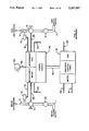
- FIG. 1 is a schematic drawing of the various components of the system of the invention
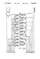
- FIG. 2A, 2B1 and 22B are schematic diagrams of the electrical circuit for the power supply and sensor receivers, including the battery monitor, AC test, pressure signal and data receivers circuit;
- FIG. 3A1, 3A2 and 3B is a schematic diagram of the electrical circuit for the operator control panel
- FIG. 4 is a schematic diagram of the electrical circuit for the pressure data transmitter which conditions the signal from the pressure transducer;
- FIG. 5 is a perspective view of the control panel of the invention.
- FIG. 6.1, FIG. 6.2, FIG. 6.3, FIG. 6.4, FIG. 6.5, FIG. 6.6, FIG. 6.7 and FIG. 6.8 are the components of a block flow diagram showing the installation and operation of the invention.
- incoming water supply line 1 and incoming gas supply line 3 provide water and gas supply respectively to a residential home or commercial business through distribution lines 2 and 4.
- Water and gas lines 1 and 3 are monitored and controlled by control panel 5 which contains a microprocessor containing the chip memory from which actions by the control panel are determined.
- control panel 5 is connected to the central computer of a "smart house" which contains the executable code.
- Pressure reducing valves 10 and 11 reduce the respective supply line pressures to a preset fixed value usually determined by the building codes.
- Solenoid valves 7 and 9 are positioned in the respective lines to permit the lines to be shut off upstream of the distribution lines 2 and 4.
- Water pressure sensor 15 and gas pressure sensor 17 are installed to sense pressure drops on the downstream side of solenoid valves 7 and 9. Sensors 15 and 17 are not in-line in the water and gas lines and so do not impede flow. They are electrically connected by conductors 19 and 21 respectively to interconnect/power supply box 34 and then to control panel 5 by electrical conductors 36, and provide a continuing signal indicative of line pressure. Solenoid valves 7 and 9 are electrically connected to control panel 5 via conductors 23 and 25 to the interconnect/power supply box 34 and electrical conductors 36 from interconnect box 34 to control panel 5, and provide a continuing signal indicative of valve position. Conductors 29 connect a burglar alarm circuit to control panel 5. Conductors 31 connect a thermostat circuit to control panel 5.
- Conductors 33 connect sprinkler and other electrically operated water system circuits to the control panel and conductors 37 connect gas furnace, gas hot water heater and other electrically operated gas system circuits. Signals from the electrically operated appliances can be wireless radio frequency controlled, eliminating the necessity for electrical conduits 33 and 37. 12-volt AC power is supplied to the interconnect/power supply box 34 by lines 39 from transformer 38, or from batteries in interconnect/power box 34. The control panel 5 is powered via conductors 36 from the interconnect/power supply box 34.
- control panel With reference to FIG. 5, the following functions are provided on the control panel:
- WATER ON/OFF switch 42 opens or shuts solenoid valve 7.
- GAS ON/OFF switch 44 opens or shuts solenoid valve 9.
- WATER SENSOR ARMING switch 43 arms the automatic shutoff circuit for the water line with a 3 minute or 20 second trigger delay depending on whether switch 49 is in the HOME or AWAY position and disarms without delay.
- GAS SENSOR ARMING switch 45 arms the automatic shutoff circuit for the gas line with a 20 second trigger delay and disarms without delay.
- VARIABLE TRIGGER DELAY switch 46 permits setting of a water line trigger delay from 3, 9 or 15 minutes for the arm delay period (set on dial 47) when the arm delay feature is activated and has one of the time period indicator lights illuminated.
- VARIABLE ARM DELAY switch 47 permits setting of a water line arm delay from no delay, 30 minutes, 1 hour or 2 hours at the trigger delay on dial 46.
- HOME/AWAY switch 49 permits the activation of the home/away feature which controls the water line trigger delay of the armed system.
- AUTOMATIC ARM select switch 50 activates the device to progressively arm itself after lack of use for the period shown on dial 47 of the ARM DELAY setting. When this time period passes and the AUTOMATIC ARM feature activates, the device will then default the HOME/AWAY switch to the HOME condition and behaves the same as if it was armed by the ARM/DISARM switches 43 and 45 in the HOME condition.
- INDICATOR LIGHTS 53 and 54 indicate when the water or gas sensors are powered respectively. Lights 53 and 54 will flash if the signal received does not equal the calibrated signal. Indicator lights 55 and 56 indicate when the water or gas circuits respectively are armed for automatic shutoff. Indicator lights 57 and 58 indicate when the water or gas shutoff circuits respectively have been triggered. Switches 42, 43, 44, 45 and 50 each has an indicator light 51 which is lit when the switch is activated.
- switches 42 or 44 overrides the automatic circuit to shut the water and gas lines off respectively.
- the closing of WATER ARMING switch 43 overrides the ARM DELAY and AUTOMATIC ARM SWITCH and arms the water system without delay.
- the arm switches 43 and 45 are closed, the flow of water or gas is governed by the automatic shutoff systems. Deactivation of the automatic shutoff system by switches 43 or 45 places the systems in normal operation.
- the control panel 5 selectively causes the solenoid valves 7 or 9 to be closed unless the selected flow conditions cease within a trigger time delay set by the HOME/AWAY switch 49 unless the ARM DELAY switch 48 has been activated in which case the trigger delay for the water line will be that set on TRIGGER DELAY switch 46 for the ARM DELAY switch 47 time delay setting and then will automatically change to the TRIGGER TIME DELAY set by the HOME/AWAY switch 49.
- the solenoid When the analyzed flow and time delay conditions meet the control panel micro-processor memory trigger conditions, the solenoid is closed the first time and the device commences the close down procedure. Ten seconds after the solenoid valve closes, it will open in order that the sensing device may monitor the line. If the device determines that the line is normal, it will cease the close down procedure and remain open. If the device determines that there is a problem, it will continue with the close down procedure.
- the microprocessor analyzes the pressure drop signal and makes an initial determination whether the pressure drop results from normal or abnormal water flow.
- the action initiated by control panel 5 is selectively based on this determination. Control panel 5 under certain conditions will initiate system checks to assist in the determination of the flow conditions.
- the preferred water pressure sensing device consists of a pressure transducer with a temperature compensation signal conditioner.
- One port for the sensor is mounted in the neck of a standard Venturi to amplify the flow signal and increase the sensitivity of the system.
- the device is connected to the Venturi in a differential manner and senses both static pressure and Venturi amplified changes in velocity pressure.
- the preferred gas pressure sensing device also consists of a pressure transducer with a temperature compensated signal conditioner.
- the device is connected to a Venturi in a differential manner and senses both static pressure and Venturi amplified changes in velocity pressure.
- Such devices can be manufactured from pressure transducers manufactured by Honeywell, Motorola and Sensym. Honeywell has developed the temperature compensated signal conditioner for the device used in this system. Honeywell's part no. is X95608-PC for gas and X94056-PC for water.
- a circuit diagram for the signal conditioner component is shown in FIG. 4.
- the present invention uses sensors which are not mounted in the flow of water or gas as in the prior art shutoff systems and therefore, does not impede flow. Losses from a properly designed Venturi are negligible. The sensors can continue to monitor whether conditions are normal even when there is no flow and will clearly indicate if there is no pressure, unlike prior art systems.
- the delay from commencement of water flow in the system to water shutoff will be a preset time, say 3 minutes, which allows for nocturnal uses such as toilet flushing, etc. If the HOME/AWAY switch 49 is set to "away”, then the delay will be much shorter, say 20 seconds, since no uses will be expected other than automatic ice makers or evaporative surges from float controlled devices.
- the trigger delay will be the time set on the TRIGGER DELAY dial 46 (between 3, 9 or 15 minutes) for a period of time set on the ARM DELAY dial 47 (0.5, 1 or 2 hours) after which time the delay will revert to the standard HOME or AWAY settings of 3 minutes or 20 seconds.
- the microprocessor in control panel 5 in fact analyzes the pressure signals caused by the water flowing and is programmed to make a determination whether the flow conditions are normal or abnormal.
- the control means may cause system checks to occur in this determination procedure. If the control means determines the pressure drop is due to normal use or supply line pressure drop, it will selectively override the "simple case" and operate in a "WATCH" condition until it receives a calibrated pressure signal indicating the line condition has returned to normal reference.
- the water line shut off system will accept and allow a signal 33 from an automatic sprinkler system to override the shut off system as long as the integrity of the water line has not been breached or the water line shut off prior to the sprinkler signal being received.
- a gas furnace and gas hot water heating system can be wired directly into the gas shutoff system via conductor 37 and if the gas line has not been breached and shut off by the shutoff system prior to the signal being received from such an appliance, then the signal will override the shutoff system.
- the appliance sensing pilot will shut down the appliance gas solenoid valve thereby removing the overriding signal to the gas line shutoff system which will set the 20 second gas system trigger delay timer going. If the gas line pressure does not normalize within that 20 second period, the gas line shutoff system will close the gas line solenoid valve, cutting off the gas flow to the house.
- the utility shut off system can be directly wired to the HOME/AWAY switch on the house thermostat by electrical conduit 31.
- the HOME/AWAY switch could then be optionally controlled from the thermostat if more convenient for the householder's routine, or the house heating and air conditioning is controlled by a central processor as in the "smart house" concept.
- This feature of remote control for the HOME/AWAY condition can also be directly controlled by an automatic thermostat, such that when the thermostat temperature set back of a programmable thermostat which would typically be at night or in the day time when the house is unoccupied, the signal controlling the set back will arm the shutoff system.
- the system can be interchangeably armed and disarmed by the ARM/DISARM switches on the monitoring panel, remotely electrically or by arming or disarming a burglar security system into which it can be directly wired and selectively coupled or decoupled by depressing a three button sequence on monitoring panel 5.
- the water utility line can also be disarmed by a water pulse from any tap in the water line as long as the system's integrity is sound. An example of this use would be: "normal settings" of HOME/AWAY set at "HOME”, ARM DELAY--"on", settings TRIGGER DELAY dial--”9 minutes", ARM DELAY dial--”1 hour”. Householder turns on dishwasher, sets burglar alarm which automatically engages utility line devices, householder washes and goes to bed. In the morning, householder uses the water pulse to disarm water line device, has shower and then comes out and disarms burglar alarm which disarms gas line device.
- the system can be set by the AUTOMATIC ARM switch 50 to arm itself based on non-use of the water system for a set period of time.
- the AUTOMATIC ARM delay in the embodiment shown uses the same time setting as for the ARM DELAY, although a separate timer could be used for this feature.
- the system will behave as if it had been armed through the ARM/DISARM switch 43 with the TRIGGER DELAY and ARM DELAY switches determining the trigger and arm delays as previously discussed, except that if the water is used normally (for a time period shorter than the TRIGGER DELAY dial setting), the automatic arm feature will reset to the beginning of the first time delay period and will not activate again unless there is no use for the set time period.
- the gas shutoff system works in similar fashion, although the default setting for both home and away delay would be about 20 seconds.
- the water line automatic arm signal would trigger the gas line arming signal.
- the utility shutoff system can be controlled by an external computer which has been programmed with the code necessary to operate the device.
- An increasing number of residences have a central computer controlling such processes as heating, air conditioning and burglar security.
- the present utility shut off system can be operated by such a correctly programmed central computer through connections 32 to the control panel 5.
- FIG. 2A, 2B1 and 2B2 is a circuit diagram illustrating the power supply 34.
- the Power system is comprised of three sections; the Power Conversion section, the Fault Monitor section, and the Solenoid Driver section.
- the Power Conversion section receives primary system power input from an external, AC transformer power source.
- a secondary, internal battery source provides backup power in the event of an interruption in the normal utility supplied AC source.
- the pressure signal is monitored only intermittently while operating on battery power.
- the external source provides a voltage which in turn is used to energize the water and gas solenoids.
- the externally supplied voltage is further conditioned to supply 5 volt logic system power through the use of a DC to DC converter.
- the battery backup source is of sufficient magnitude to permit a drop in voltage at the input of the converter (as a result of normal battery degradation) without loss of 5 volt regulation to the logic system.
- the primary element in the Power Conversion section is item L01, the switching voltage regulator.
- the device is configured as a negative to positive, boost converter, through the incorporation of components L01, D02, R01, R09, R08, C02, C03 and Q01.
- Diode D01 provides isolation of the two input power sources which allows the AC to DC source to predominate over that of the battery backup source.
- Capacitors C01 and C04 and inductor L02 are used to provide noise immunity and/or to maintain output regulation.
- the Fault Monitor section has the capability of indicating three fault conditions that may occur in the Power Conversion section:
- AC-OFF when active, indicates that the AC transformer power source is no longer supplying input power to the DC to DC converter. (The input power is being supplied by the battery backup source).
- the input power is being supplied by the battery backup source.
- R40, R41, R42, and C13 provide the proper biasing and voltage translation to turn Q25 ON or OFF in response to the state of Q24. These latter components also yield a system compatible TTL Voltage swing.
- C11 and C12 provide input signal filtering.
- LOW BATTERY when active, indicates that the battery backup, input voltage is low enough to warrant battery replacement.
- a predetermined low battery input source level is detected and provides the proper input bias to turn Q22 OFF as a result.
- R35, R36, R37, and C10 provide the proper biasing and voltage translation to turn Q23 ON or OFF in response to the state of Q22. These latter components also yield a system compatible TTL voltage swing.
- C07 and C08 provide input signal filtering.
- BATTERY FAULT when active, indicates that the battery backup, input voltage is too low to sustain normal system operation.
- R28 and R29 Through the voltage divider network R28 and R29, a predetermined lower battery input source level is detected and provides the proper input bias to turn Q20 OFF as a result.
- R30, R31, R34, and C09 provide the proper biasing and voltage translation to turn Q21 ON or OFF in response to the state of Q20. These latter components also yield a system compatible TTL voltage swing.
- C11 and C12 provide input signal filtering.
- the solenoid drive section comprises four identical circuits, driven by four separate input control lines:
- Gas On--R06, R18, R19, and R26 provide proper biasing and voltage level translation to turn Q06 and Q18 ON and OFF in response to the voltage level of the input control signal, Gas On. Q12 turns ON and OFF in response to the switched state of Q18.
- Q12 is a high current, FET switching device which is used to activate the Gas Open solenoid.
- Gas Off--R05, R16, R17, and R25 provide proper biasing and voltage level translation to turn Q05 and Q17 ON and OFF in response to the voltage level of the input control signal, Gas Off.
- Q11 turns ON and OFF in response to the switched state of Q17.
- Q11 is a high current, FET switching device which is used to activate the Gas Close solenoid.
- H 2 O On--R04, R14, R15, and R24 provide proper biasing and voltage level translation to turn Q04 and Q16 ON and OFF in response to the voltage level of the input control signal, H 2 O On.
- Q10 turns ON and OFF in response to the switched state of Q16.
- Q10 is a high current, FET switching device which is used to activate the Water Open solenoid.
- H 2 O Off--R03, R12, R13, and R23 provide proper biasing and voltage level translation to turn Q03 and Q15 ON and OFF in response to the voltage level of the input control signal, H 2 O Off.
- Q09 turns ON and OFF in response to the switched stage of Q15.
- Q09 is a high current, FET switching device which is used to activate the Water Close solenoid.
- FIG. 3A1, 3A2 and 3B illustrates a circuit diagram for the operator control panel 5.
- the heart of the Operator Control Panel is a Z86C21 8-bit microcontroller, containing the operating control program in non-volatile read-only memory (ROM).
- ROM read-only memory
- the program not only controls the inputs and outputs of the console but also lights the appropriate panel indicators (LED1-LED20), as appropriate, by way of U2 and U6.
- the timing for the program is established by Y1, C1, and C2, forming a crystal oscillator circuit.
- U2 (74LS244) is used as a current amplifier, providing sufficient current to light LED1-LED20 on the front panel.
- the LEDs are lit at different times based on the output configuration of U6 (74L8190).
- This multiplexer allows only one of its outputs to drop to a low logic state at any one time, based on the state of the input lines from U1. During the time that a U6 output line is low and the appropriate output from U1 is at a logic high level, the LED connected between them will light. Internal resistors in the LED package limit the current flow for that LED.
- U1's program sequences through all combinations of U6, allowing each LED to be lit, as appropriate. Due to the repetition rate of this scan sequence, the LEDs appear to the human eye to the constantly lit, even though they are each lit for approximately 1/8 of the scan cycle.
- U1 can detect the closure of the appropriate front panel switch (S1-S8).
- S1-S8 the appropriate front panel switch
- the SWIN line of U1 is pulled from a high logic state to a low state, allowing U1 to "sense" the switch closure.
- the switch is released, the SWIN line is pulled to an inactive or high state by R3 connected to +5 V.
- U5 (74LS123) monitors the activity of the MUX enable line from U1 to U6, R1, R2, C9 and C10 provide fixed timing for the monitoring function. If the MUX Enable line is inactive longer than the preset time interval, U5 will activate the RESET line of U1, thus restarting the program in U1.
- U3 (74C00) is used as a single-chip multiplexor, allowing two separate sensor lines to be monitored by the same input line of U1, based on the logic state of Sensor MUX1.
- U4 (74C00) multiplexes two sensor outputs to another input of U1 based on the logic state of sensor MUX2.
- L1, C3 and C4 are used to filter power supply fluctuations entering the operator console.
- Capacitors C11-C15 are used to further filter noise from the power supply before it reaches the ICs next to which they are mounted.
- FIG. 6.1, FIG. 6.2, FIG. 6.3, FIG. 6.4, FIG. 6.5, FIG. 6.6, FIG. 6.7 and FIG. 6.8 is a flow chart illustrating in detail the installation and testing procedures for the invention.
Abstract
The present invention provides an automatic monitoring and shutoff system for utilities which allows the user to set the system to permit certain uses of gas or water without triggering the shutoff, depending on whether the user is home or away, and is able to provide for specific usual or unusual uses.
Description
The present invention relates to systems for automatically shutting off water supply, natural gas or other utilities in the event of unexpected leakage.
While a home-owner will typically shut off water and gas utilities in a home, cottage or ski chalet when leaving the residence unoccupied for an extended period, this will often not be done when the residence is left unoccupied for a shorter period, perhaps a weekend or even several weeks and is never done at night while the residence is occupied. However, if a water or gas leak occurs during the vacant period or overnight, considerable damage can be done, even over a very short period. Leaks might be caused by freezing or breakage of pipes, for example, or an earthquake.
Various systems have been designed to automatically shut off water or gas supplies to a household in the event of earthquakes or leakage. Some of these are triggered by the tremors of the earthquake. Others rely on sensing a flow in the water line. For example, U.S. Pat. No. 3,416,560 issued Dec. 17, 1968 to Bruno discloses a fluid leak monitoring apparatus which comprises a housing with a chamber therein divided into a small diameter intake chamber and a larger diameter outlet chamber. A piston is mounted in the larger chamber so that it faces downstream. A drop in the water pressure downstream due to a leak causes the piston to move in the downstream direction, throwing a switch which activates a shutoff valve.
U.S. Pat. No. 4,180,088 issued Dec. 25, 1979 to Mallett discloses another water shutoff system in which a fluid flow sensor causes water and gas supplies to be shut off when water flow is sensed and the circuit is set to automatic mode, but not otherwise. U.S. Pat. No. 4,249,565 issued Feb. 10, 1981 to Brust and U.S. Pat. No. 4,589,435 issued May 20, 1986 to Aldrich disclose timed water shutoff systems in which water is permitted to flow for a pre-set period of time before the shutoff valve is activated. Finally, U.S. Pat. No. 4,730,637 issued Mar. 15, 1988 to White discloses another water and gas shutoff system which uses a central processing unit to monitor data concerning fluid flow and temperature in the pipes and, based on the data, decides when to shut the supply of fluid to the system.
The above referenced devices cannot determine the status of the utility line once they have triggered. Utility line monitoring is not possible with sensing devices that return to equilibrium when flow stops whether under normal conditions or abnormal conditions such as voiding of the utility line after line failure and triggering of the line shut off valve. Such systems would have to be electrically activated in order for their sensing device to determine the presence or absence of flow. Building codes specifically prohibit such automatic resetting for the gas utility line and undesirable flooding could occur from the water line.
White addresses this problem for one type of potential failure in the water line by suggesting temperature measurement and trigger line shut off and water system draining. This differs from commercially available temperature monitoring alarm systems in as much as it allows for draining and the charging of the water line when the sensing condition has passed. Presumably if some problem has occurred such as earthquake failure or freezing due to inadequate draining caused by line vacuum and water tension that occurs when a non-vented line is drained, the White device would then function similarly to other flow sensing devices.
The present invention provides an automatic utilities shutoff system for shutting off a water or gas supply line in the event of line leakage or breakage, which comprises:
a) valve means for opening and closing the water or gas supply line;
b) control means for controlling the valve means;
c) means for sensing a pressure change in the water or gas supply line caused by flow in the water or gas supply line;
d) means for the sensing means to send a signal to the control means;
e) system arming means to selectively cause the control means to close the valve in response to a signal indicating a flow in the water or gas supply line;
f) first trigger time delay means for activating said control means to close said valve after a predetermined duration of flow in said supply lines;
g) second trigger time delay means for overriding said first trigger time delay with second trigger time delay for a predetermined period of time;
h) means for setting a variable time period for which said second trigger time delay overrides said first trigger time delay; and
i) automatic arming means to selectively activate said arming means and said time delays in response to a signal indicative of lack of flow in said supply line.
In drawings which illustrate a preferred embodiment of the invention:
FIG. 1 is a schematic drawing of the various components of the system of the invention;
FIG. 2A, 2B1 and 22B are schematic diagrams of the electrical circuit for the power supply and sensor receivers, including the battery monitor, AC test, pressure signal and data receivers circuit;
FIG. 3A1, 3A2 and 3B is a schematic diagram of the electrical circuit for the operator control panel;
FIG. 4 is a schematic diagram of the electrical circuit for the pressure data transmitter which conditions the signal from the pressure transducer;
FIG. 5 is a perspective view of the control panel of the invention; and
FIG. 6.1, FIG. 6.2, FIG. 6.3, FIG. 6.4, FIG. 6.5, FIG. 6.6, FIG. 6.7 and FIG. 6.8 are the components of a block flow diagram showing the installation and operation of the invention.
With reference to FIG. 1, incoming water supply line 1 and incoming gas supply line 3 provide water and gas supply respectively to a residential home or commercial business through distribution lines 2 and 4. Water and gas lines 1 and 3 are monitored and controlled by control panel 5 which contains a microprocessor containing the chip memory from which actions by the control panel are determined. Alternatively, control panel 5 is connected to the central computer of a "smart house" which contains the executable code. Pressure reducing valves 10 and 11 reduce the respective supply line pressures to a preset fixed value usually determined by the building codes. Solenoid valves 7 and 9 are positioned in the respective lines to permit the lines to be shut off upstream of the distribution lines 2 and 4. Water pressure sensor 15 and gas pressure sensor 17 are installed to sense pressure drops on the downstream side of solenoid valves 7 and 9. Sensors 15 and 17 are not in-line in the water and gas lines and so do not impede flow. They are electrically connected by conductors 19 and 21 respectively to interconnect/power supply box 34 and then to control panel 5 by electrical conductors 36, and provide a continuing signal indicative of line pressure. Solenoid valves 7 and 9 are electrically connected to control panel 5 via conductors 23 and 25 to the interconnect/power supply box 34 and electrical conductors 36 from interconnect box 34 to control panel 5, and provide a continuing signal indicative of valve position. Conductors 29 connect a burglar alarm circuit to control panel 5. Conductors 31 connect a thermostat circuit to control panel 5. Conductors 33 connect sprinkler and other electrically operated water system circuits to the control panel and conductors 37 connect gas furnace, gas hot water heater and other electrically operated gas system circuits. Signals from the electrically operated appliances can be wireless radio frequency controlled, eliminating the necessity for electrical conduits 33 and 37. 12-volt AC power is supplied to the interconnect/power supply box 34 by lines 39 from transformer 38, or from batteries in interconnect/power box 34. The control panel 5 is powered via conductors 36 from the interconnect/power supply box 34.
With reference to FIG. 5, the following functions are provided on the control panel:
1. WATER ON/OFF switch 42 opens or shuts solenoid valve 7.
2. GAS ON/OFF switch 44 opens or shuts solenoid valve 9.
3. WATER SENSOR ARMING switch 43 arms the automatic shutoff circuit for the water line with a 3 minute or 20 second trigger delay depending on whether switch 49 is in the HOME or AWAY position and disarms without delay.
4. GAS SENSOR ARMING switch 45 arms the automatic shutoff circuit for the gas line with a 20 second trigger delay and disarms without delay.
5. VARIABLE TRIGGER DELAY switch 46 permits setting of a water line trigger delay from 3, 9 or 15 minutes for the arm delay period (set on dial 47) when the arm delay feature is activated and has one of the time period indicator lights illuminated.
6. VARIABLE ARM DELAY switch 47 permits setting of a water line arm delay from no delay, 30 minutes, 1 hour or 2 hours at the trigger delay on dial 46.
7. HOME/AWAY switch 49 permits the activation of the home/away feature which controls the water line trigger delay of the armed system.
8. AUTOMATIC ARM select switch 50 activates the device to progressively arm itself after lack of use for the period shown on dial 47 of the ARM DELAY setting. When this time period passes and the AUTOMATIC ARM feature activates, the device will then default the HOME/AWAY switch to the HOME condition and behaves the same as if it was armed by the ARM/DISARM switches 43 and 45 in the HOME condition.
9. LOW BATTERY LIGHT 52 flashes when the back up battery needs replacing.
10. INDICATOR LIGHTS 53 and 54 indicate when the water or gas sensors are powered respectively. Lights 53 and 54 will flash if the signal received does not equal the calibrated signal. Indicator lights 55 and 56 indicate when the water or gas circuits respectively are armed for automatic shutoff. Indicator lights 57 and 58 indicate when the water or gas shutoff circuits respectively have been triggered. Switches 42, 43, 44, 45 and 50 each has an indicator light 51 which is lit when the switch is activated.
The opening of switches 42 or 44 overrides the automatic circuit to shut the water and gas lines off respectively. The closing of WATER ARMING switch 43 overrides the ARM DELAY and AUTOMATIC ARM SWITCH and arms the water system without delay. When the arm switches 43 and 45 are closed, the flow of water or gas is governed by the automatic shutoff systems. Deactivation of the automatic shutoff system by switches 43 or 45 places the systems in normal operation. When these systems are activated and sensors 15 and 17 sense a pressure change indicating a fluid flow, the control panel 5 selectively causes the solenoid valves 7 or 9 to be closed unless the selected flow conditions cease within a trigger time delay set by the HOME/AWAY switch 49 unless the ARM DELAY switch 48 has been activated in which case the trigger delay for the water line will be that set on TRIGGER DELAY switch 46 for the ARM DELAY switch 47 time delay setting and then will automatically change to the TRIGGER TIME DELAY set by the HOME/AWAY switch 49.
When the analyzed flow and time delay conditions meet the control panel micro-processor memory trigger conditions, the solenoid is closed the first time and the device commences the close down procedure. Ten seconds after the solenoid valve closes, it will open in order that the sensing device may monitor the line. If the device determines that the line is normal, it will cease the close down procedure and remain open. If the device determines that there is a problem, it will continue with the close down procedure.
The microprocessor analyzes the pressure drop signal and makes an initial determination whether the pressure drop results from normal or abnormal water flow. The action initiated by control panel 5 is selectively based on this determination. Control panel 5 under certain conditions will initiate system checks to assist in the determination of the flow conditions.
The preferred water pressure sensing device consists of a pressure transducer with a temperature compensation signal conditioner. One port for the sensor is mounted in the neck of a standard Venturi to amplify the flow signal and increase the sensitivity of the system. The device is connected to the Venturi in a differential manner and senses both static pressure and Venturi amplified changes in velocity pressure. The preferred gas pressure sensing device also consists of a pressure transducer with a temperature compensated signal conditioner. The device is connected to a Venturi in a differential manner and senses both static pressure and Venturi amplified changes in velocity pressure. Such devices can be manufactured from pressure transducers manufactured by Honeywell, Motorola and Sensym. Honeywell has developed the temperature compensated signal conditioner for the device used in this system. Honeywell's part no. is X95608-PC for gas and X94056-PC for water. A circuit diagram for the signal conditioner component is shown in FIG. 4.
As will be seen, the present invention uses sensors which are not mounted in the flow of water or gas as in the prior art shutoff systems and therefore, does not impede flow. Losses from a properly designed Venturi are negligible. The sensors can continue to monitor whether conditions are normal even when there is no flow and will clearly indicate if there is no pressure, unlike prior art systems.
Looking first at the water shutoff system, in the event the ARM DELAY switch 47 is "off" and the HOME/AWAY switch 49 is set to "home", the delay from commencement of water flow in the system to water shutoff will be a preset time, say 3 minutes, which allows for nocturnal uses such as toilet flushing, etc. If the HOME/AWAY switch 49 is set to "away", then the delay will be much shorter, say 20 seconds, since no uses will be expected other than automatic ice makers or evaporative surges from float controlled devices. If the ARM DELAY switch 47 is "on", then the trigger delay will be the time set on the TRIGGER DELAY dial 46 (between 3, 9 or 15 minutes) for a period of time set on the ARM DELAY dial 47 (0.5, 1 or 2 hours) after which time the delay will revert to the standard HOME or AWAY settings of 3 minutes or 20 seconds.
In the simple case, for example, the householder is leaving the house for an extended period and thus places the HOME/AWAY switch in the "away" position and arms the system. Now any flow of water of greater than 20 seconds duration will cause the water supply close down procedure to be initiated. On returning home, he places the switch in the "home" position which now allows a 3 minute flow when the system is armed at night to allow for toilet flushing and the like. If there will be an unusual nocturnal use extending longer than 3 minutes, say a householder bathes, then the ARM DELAY switch can be activated. It will accommodate a longer flow (3 to 15 minutes) without shutting off the system, and this extended delay feature will remain active for a limited duration as selected on ARM DELAY switch 47. After that time, the delay reverts to the preset HOME or AWAY delay.
The microprocessor in control panel 5 in fact analyzes the pressure signals caused by the water flowing and is programmed to make a determination whether the flow conditions are normal or abnormal. The control means may cause system checks to occur in this determination procedure. If the control means determines the pressure drop is due to normal use or supply line pressure drop, it will selectively override the "simple case" and operate in a "WATCH" condition until it receives a calibrated pressure signal indicating the line condition has returned to normal reference.
The water line shut off system will accept and allow a signal 33 from an automatic sprinkler system to override the shut off system as long as the integrity of the water line has not been breached or the water line shut off prior to the sprinkler signal being received. Similarly, a gas furnace and gas hot water heating system can be wired directly into the gas shutoff system via conductor 37 and if the gas line has not been breached and shut off by the shutoff system prior to the signal being received from such an appliance, then the signal will override the shutoff system.
Should catastrophic failure occur while such directly wired appliances are operating and overriding the gas shutoff system, the appliance sensing pilot will shut down the appliance gas solenoid valve thereby removing the overriding signal to the gas line shutoff system which will set the 20 second gas system trigger delay timer going. If the gas line pressure does not normalize within that 20 second period, the gas line shutoff system will close the gas line solenoid valve, cutting off the gas flow to the house.
The utility shut off system can be directly wired to the HOME/AWAY switch on the house thermostat by electrical conduit 31. The HOME/AWAY switch could then be optionally controlled from the thermostat if more convenient for the householder's routine, or the house heating and air conditioning is controlled by a central processor as in the "smart house" concept. This feature of remote control for the HOME/AWAY condition can also be directly controlled by an automatic thermostat, such that when the thermostat temperature set back of a programmable thermostat which would typically be at night or in the day time when the house is unoccupied, the signal controlling the set back will arm the shutoff system.
The system can be interchangeably armed and disarmed by the ARM/DISARM switches on the monitoring panel, remotely electrically or by arming or disarming a burglar security system into which it can be directly wired and selectively coupled or decoupled by depressing a three button sequence on monitoring panel 5. The water utility line can also be disarmed by a water pulse from any tap in the water line as long as the system's integrity is sound. An example of this use would be: "normal settings" of HOME/AWAY set at "HOME", ARM DELAY--"on", settings TRIGGER DELAY dial--"9 minutes", ARM DELAY dial--"1 hour". Householder turns on dishwasher, sets burglar alarm which automatically engages utility line devices, householder washes and goes to bed. In the morning, householder uses the water pulse to disarm water line device, has shower and then comes out and disarms burglar alarm which disarms gas line device.
The system can be set by the AUTOMATIC ARM switch 50 to arm itself based on non-use of the water system for a set period of time. The AUTOMATIC ARM delay in the embodiment shown, uses the same time setting as for the ARM DELAY, although a separate timer could be used for this feature. If the AUTOMATIC ARM switch 50 is "on", at the expiration of the time period shown on the ARM DELAY dial 47, the system will behave as if it had been armed through the ARM/DISARM switch 43 with the TRIGGER DELAY and ARM DELAY switches determining the trigger and arm delays as previously discussed, except that if the water is used normally (for a time period shorter than the TRIGGER DELAY dial setting), the automatic arm feature will reset to the beginning of the first time delay period and will not activate again unless there is no use for the set time period.
There is a greater use for the AUTOMATIC ARM feature than just the added insurance for those who forget to arm. For example, a neighbour could disarm the water line through the water pulse means, without disturbing the burglar security alarm or gas utility line system, water the gardens, and the system would automatically rearm itself in the time period shown on the ARM DELAY dial 47.
The gas shutoff system works in similar fashion, although the default setting for both home and away delay would be about 20 seconds. The water line automatic arm signal would trigger the gas line arming signal.
The utility shutoff system can be controlled by an external computer which has been programmed with the code necessary to operate the device. An increasing number of residences have a central computer controlling such processes as heating, air conditioning and burglar security. The present utility shut off system can be operated by such a correctly programmed central computer through connections 32 to the control panel 5.
FIG. 2A, 2B1 and 2B2 is a circuit diagram illustrating the power supply 34. The Power system is comprised of three sections; the Power Conversion section, the Fault Monitor section, and the Solenoid Driver section.
The Power Conversion section receives primary system power input from an external, AC transformer power source. A secondary, internal battery source provides backup power in the event of an interruption in the normal utility supplied AC source. To conserve battery power, the pressure signal is monitored only intermittently while operating on battery power.
The external source provides a voltage which in turn is used to energize the water and gas solenoids. In addition, the externally supplied voltage is further conditioned to supply 5 volt logic system power through the use of a DC to DC converter.
The battery backup source is of sufficient magnitude to permit a drop in voltage at the input of the converter (as a result of normal battery degradation) without loss of 5 volt regulation to the logic system.
The primary element in the Power Conversion section is item L01, the switching voltage regulator. The device is configured as a negative to positive, boost converter, through the incorporation of components L01, D02, R01, R09, R08, C02, C03 and Q01. Diode D01 provides isolation of the two input power sources which allows the AC to DC source to predominate over that of the battery backup source. Capacitors C01 and C04 and inductor L02 are used to provide noise immunity and/or to maintain output regulation.
The Fault Monitor section has the capability of indicating three fault conditions that may occur in the Power Conversion section:
AC-OFF, when active, indicates that the AC transformer power source is no longer supplying input power to the DC to DC converter. (The input power is being supplied by the battery backup source). Through the voltage divider network R38 and R39, the presence or absence of the AC to DC input source is detected and provides the proper input bias to turn Q24 ON or OFF respectively. R40, R41, R42, and C13 provide the proper biasing and voltage translation to turn Q25 ON or OFF in response to the state of Q24. These latter components also yield a system compatible TTL Voltage swing. C11 and C12 provide input signal filtering.
LOW BATTERY, when active, indicates that the battery backup, input voltage is low enough to warrant battery replacement. Through the voltage divider network R32 and R33, a predetermined low battery input source level is detected and provides the proper input bias to turn Q22 OFF as a result. R35, R36, R37, and C10 provide the proper biasing and voltage translation to turn Q23 ON or OFF in response to the state of Q22. These latter components also yield a system compatible TTL voltage swing. C07 and C08 provide input signal filtering.
BATTERY FAULT, when active, indicates that the battery backup, input voltage is too low to sustain normal system operation. Through the voltage divider network R28 and R29, a predetermined lower battery input source level is detected and provides the proper input bias to turn Q20 OFF as a result. R30, R31, R34, and C09 provide the proper biasing and voltage translation to turn Q21 ON or OFF in response to the state of Q20. These latter components also yield a system compatible TTL voltage swing. C11 and C12 provide input signal filtering.
The solenoid drive section comprises four identical circuits, driven by four separate input control lines:
Gas On--R06, R18, R19, and R26 provide proper biasing and voltage level translation to turn Q06 and Q18 ON and OFF in response to the voltage level of the input control signal, Gas On. Q12 turns ON and OFF in response to the switched state of Q18. Q12 is a high current, FET switching device which is used to activate the Gas Open solenoid.
Gas Off--R05, R16, R17, and R25 provide proper biasing and voltage level translation to turn Q05 and Q17 ON and OFF in response to the voltage level of the input control signal, Gas Off. Q11 turns ON and OFF in response to the switched state of Q17. Q11 is a high current, FET switching device which is used to activate the Gas Close solenoid.
H2 O On--R04, R14, R15, and R24 provide proper biasing and voltage level translation to turn Q04 and Q16 ON and OFF in response to the voltage level of the input control signal, H2 O On. Q10 turns ON and OFF in response to the switched state of Q16. Q10 is a high current, FET switching device which is used to activate the Water Open solenoid.
H2 O Off--R03, R12, R13, and R23 provide proper biasing and voltage level translation to turn Q03 and Q15 ON and OFF in response to the voltage level of the input control signal, H2 O Off. Q09 turns ON and OFF in response to the switched stage of Q15. Q09 is a high current, FET switching device which is used to activate the Water Close solenoid.
FIG. 3A1, 3A2 and 3B illustrates a circuit diagram for the operator control panel 5. The heart of the Operator Control Panel is a Z86C21 8-bit microcontroller, containing the operating control program in non-volatile read-only memory (ROM). The program not only controls the inputs and outputs of the console but also lights the appropriate panel indicators (LED1-LED20), as appropriate, by way of U2 and U6. The timing for the program is established by Y1, C1, and C2, forming a crystal oscillator circuit.
U2 (74LS244) is used as a current amplifier, providing sufficient current to light LED1-LED20 on the front panel. In order to minimize the number of control lines and reduce power consumption, the LEDs are lit at different times based on the output configuration of U6 (74L8190). This multiplexer allows only one of its outputs to drop to a low logic state at any one time, based on the state of the input lines from U1. During the time that a U6 output line is low and the appropriate output from U1 is at a logic high level, the LED connected between them will light. Internal resistors in the LED package limit the current flow for that LED.
U1's program sequences through all combinations of U6, allowing each LED to be lit, as appropriate. Due to the repetition rate of this scan sequence, the LEDs appear to the human eye to the constantly lit, even though they are each lit for approximately 1/8 of the scan cycle.
During the same time that a LED is being lit, U1 can detect the closure of the appropriate front panel switch (S1-S8). When the appropriate output of U6 goes low, the SWIN line of U1 is pulled from a high logic state to a low state, allowing U1 to "sense" the switch closure. When the switch is released, the SWIN line is pulled to an inactive or high state by R3 connected to +5 V.
U5 (74LS123) monitors the activity of the MUX enable line from U1 to U6, R1, R2, C9 and C10 provide fixed timing for the monitoring function. If the MUX Enable line is inactive longer than the preset time interval, U5 will activate the RESET line of U1, thus restarting the program in U1.
U3 (74C00) is used as a single-chip multiplexor, allowing two separate sensor lines to be monitored by the same input line of U1, based on the logic state of Sensor MUX1. Likewise, U4 (74C00) multiplexes two sensor outputs to another input of U1 based on the logic state of sensor MUX2.
L1, C3 and C4 are used to filter power supply fluctuations entering the operator console. Capacitors C11-C15 are used to further filter noise from the power supply before it reaches the ICs next to which they are mounted.
FIG. 6.1, FIG. 6.2, FIG. 6.3, FIG. 6.4, FIG. 6.5, FIG. 6.6, FIG. 6.7 and FIG. 6.8 is a flow chart illustrating in detail the installation and testing procedures for the invention.
As will be apparent to those skilled in the art, various modifications and adaptations of the structure above described may be made without departing from the spirit of the invention, the scope of which is to be constructed in accordance with the accompanying claims.
______________________________________
BOARD CONNECTOR LEGEND
        LET-
FIGURE  TER     CONNECTOR        LINE
______________________________________
2A      A       TB004-01
        B       TB004-02
        C       TB002-01         +5 VDC
        D       TB002-11         SENSOR PWR
        E       TB002-04         WATER OFF
        F       TB002-05         WATER ON
        G       TB002-07         GAS OFF
        H       TB002-06         GAS ON
        I       TB002-09         TSTAC
        J       TB002-02         GND
        K       B-
        L       AC
        M       TB005-01         GAS ON
        N       TB005-03         GAS OFF
        O       TB005-04         WATER ON
        P       TB005-06         WATER OFF
        Q       SNRPWR           SENSOR PWR
        R       BATT FAULT       BATT FAULT
2B1     A       +5 VDC
        B       GND
        C       D-
        D       BATT FAULT
        E       AC
        F       TB02-13          LOW
                                 BATTERY
        G       TB02-12          BATTERY
                                 FAULT
        H       TB02-14          AC OFF
2B2     I       SNRPWR
        J       TB05-11          WSNR (+)
        K       TB05-12          WSNR (-)
        L       TB05-13          GSNR +
        M       TB05-14          GSNR -
        N       TB02-16          WSNR
        O       GND
        P       TB02-03          GSNR
3A1     A       H20 SENSOR
        B       GAS SENSOR
        C       GAS APPLIANCE
        D       BURGLER IN
        E       WATER APPLIANCE
        F       WATER HALL OUT
        G       GAS HALL OUT
        H       AC OFF
        I       LOW BATTERY
        J       BATTERY FAULT
        K       P36
        L       WCLIN
        M       WOPIN
        N       GOPIN
        O       GCLIN
3A2     P       +5 V IN
        Q       GROUND
        A       PRS SNR          +12V
        B       PRS SNR          OUT
        C       PRS SNR          GND
        D       OUTPUT +
        E       OUTPUT -
______________________________________
COMPONENT LEGEND
FIGURE  COMPONENT    VALUE
______________________________________
2A      R01-R07      50K
        R08          2.2K
        R09          56K
        R10-R27      50K
        L01          50 μH
        L02          100 μH
        D01-D02      MBR330
        D03          BRIDGE
        Q01-Q07      2N3906
        Q08-Q13      IFRD 9020
        Q14-Q19      3904
        C01          220 μF
        C02          0.01 μF
        C03-C04      220 μF
        F01          FUSE 2 A SLO
2B1     R28          1.0M
        R29          40K
        R30          470K
        R31          2.2M
        R32          47K
        R33          1.0M
        R34-R35      2.2M
        R36          470
        R37          2.2M
        R38          1.0M
        R39          47K
        R40          2.2M
        R41          470K
        C07-C08      0.01 μF
        C09-C11      220 μF
        C12          0.01 μF
        C13          220 μF
        Q20          2N3904
        Q21          2N3906
        Q22          2N3904
2B1     Q23          2N3906
        Q24          2N3904
        Q25          RNB906
2B2     R42          2.2M
        R43          18
        R44          100K
        R45          10K
        R46          18
        R47          100K
        R48          10K
        R49-R50      560
        R51          4.7K
        R52          100K
        R53          10K
        R54          4.7K
        R55          100K
        R56          10K
        R57          100K
        R58          22K
        R59          100K
        R60          22K
        R61          100K
        R62          27K
        R63          100K
        R64          27K
        R65          10K
        R66          1M
        R67          10K
        R68          1M
        R69-R70      6.8K
        C3-C6        0.01 μF
3A1     R1           100 kΩ
        R2           10 kΩ
        C1,C2        15 pf
        U1           Z86C21 MCU
        U2           74LS244
        U3           74C00
        U3,U4        74C00
        Y1           12.000 MHz
3A2     R3           1 MΩ
        D1           WVO LED
        D2           WTrig LED
        D3           WArm LED
        D4           WN LED
        D5           Wlogo LED
        D6           WSA LED
        D7           GSA LED
        D8           GVO LED
        D9           GTrig LED
        D10          GArm LED
        D11          GN LED
        D12          0.5 LED
        D13          1.0 LED
        D14          2.0 LED
        D15          3 LED
        D16          9 LED
        D17          15 LED
        D18          Home LED
        D19          Away LED
        D20          Low Batt LED
        D21          Glogo LED
        D22          A'Arm LED
        S1           WVOS
        S2           WVAS
        S3           GVAS
        S4           GVOS
        S5           ADS
        S6           TDS
        S7           HA
        S8           AArm
        L1           100 μH
        C3,C4        100 μF
3B      C11-C15      0.01 μF
        R1           6.8K (TEMP STABLE)
        R2           240
        R3           91K (TEMP STABLE)
4       R4           50K FS SET (TEMP STABLE)
        R5           22K
        R6           1K
        R7           100K
        R8           16.5K (TEMP STABLE)
        R9           620
        R10          2K NULL SET
        R11          500 Vr SET
        R12          2.7K
        C1           0.47 μF
        C2, C3       0.1 μF
        C4           0.0047 μF (TEMP STABLE)
        U1           LM317 LZ
        U2           RC 4152
______________________________________
Claims (12)
1. An automatic shutoff system for a water or gas supply line comprising:
a) valve means for opening and closing said water or gas supply line;
b) control means for controlling said valve means;
c) means for sensing a pressure change in said water or gas supply line caused by flow in said water or gas supply line;
d) means for said sensing means to send a signal to said control means;
e) system arming means to selectively cause said control means to close said valve in response to a signal indicating a flow in said water or gas supply line;
f) first trigger time delay means for activating said control means to close said valve after a predetermined duration of flow in said water or gas supply line;
g) second trigger time delay means for overriding said first trigger time delay with second trigger time delay for a predetermined period of time; and
h) means for setting a variable time period for which said second trigger time delay overrides said first trigger time delay.
2. The system of claim 1 further comprising:
j) means for automatically analyzing supply line pressure and calibrating control means for varying supply line pressures.
3. The system of claim 1 further comprising:
k) water pulse disarming means to selectively disarm said system arming in response to a signal indicative of a flow in said line for a predetermined period of time.
4. The system of claim 1 further comprising
l) means for remote activation of said system arming means.
5. The system of claim 1 further comprising:
m) means for magnetically maintaining said valve in its open or closed position.
6. The system of claim 1 further comprising:
n) monitoring panel means for operation and display of said system and automatic arming and each said time delay means.
7. The system of claim 1 further comprising:
o) means for overriding said system arming means by a control signal.
8. The system of claim 1 further comprising:
p) means for manually opening said valve.
9. The system of claim 1 wherein said control means and sensing means are electrically operated, further comprising a source of AC power and auxiliary battery means, and means for selective monitoring of said pressure sensing means when said system is operating on said battery power.
10. The system of claim 1 further comprising:
q) monitoring means for determining whether said valve is in its magnetically maintained open or closed position.
11. The system of claim 1 further comprising:
i) automatic arming means to selectively activate said system arming means and each said time delay means in response to a signal indicative of lack of flow in said supply line.
12. The system of claim 1 comprising both water and gas supply lines.
Priority Applications (3)
| Application Number | Priority Date | Filing Date | Title |
|---|---|---|---|
| US07/864,677 US5267587A (en) | 1992-04-07 | 1992-04-07 | Utilities shutoff system |
| PCT/CA1993/000154 WO1993020425A1 (en) | 1992-04-07 | 1993-04-06 | Utilities shutoff system |
| AU38854/93A AU3885493A (en) | 1992-04-07 | 1993-04-06 | Utilities shutoff system |
Applications Claiming Priority (1)
| Application Number | Priority Date | Filing Date | Title |
|---|---|---|---|
| US07/864,677 US5267587A (en) | 1992-04-07 | 1992-04-07 | Utilities shutoff system |
Publications (1)
| Publication Number | Publication Date |
|---|---|
| US5267587A true US5267587A (en) | 1993-12-07 |
Family
ID=25343816
Family Applications (1)
| Application Number | Title | Priority Date | Filing Date |
|---|---|---|---|
| US07/864,677 Expired - Lifetime US5267587A (en) | 1992-04-07 | 1992-04-07 | Utilities shutoff system |
Country Status (3)
| Country | Link |
|---|---|
| US (1) | US5267587A (en) |
| AU (1) | AU3885493A (en) |
| WO (1) | WO1993020425A1 (en) |
Cited By (61)
| Publication number | Priority date | Publication date | Assignee | Title |
|---|---|---|---|---|
| US5515883A (en) * | 1994-06-30 | 1996-05-14 | Bouzaglou; David | Waste line stoppage detector and automatic water shutoff system |
| US5650564A (en) * | 1995-06-08 | 1997-07-22 | Wodeslavsky; Josef | Fluid drip detection system |
| EP0794381A2 (en) * | 1996-03-06 | 1997-09-10 | Judo Wasseraufbereitung GmbH | Water damage protection device |
| US5913236A (en) * | 1997-05-22 | 1999-06-15 | Wodeslavsky; Josef | Protection system for hydraulic systems against leaks/floods, freezing and pressure |
| US5921266A (en) * | 1997-06-03 | 1999-07-13 | Mapco, Inc. | Safety system for transfer of pressurized fluid |
| US5934302A (en) * | 1996-05-01 | 1999-08-10 | Nemelka; Mark S. | Control valve apparatus and method for regulating fluid flow in fluid-intake machines |
| US5967175A (en) * | 1996-02-15 | 1999-10-19 | Direct, Plumbing, Heating & Rooter, Inc. | Waste line stoppage detector and automatic water shutoff system |
| US6164319A (en) * | 1997-04-04 | 2000-12-26 | Cochran; David J. | Automatic shut-off device for a pipe |
| US6237618B1 (en) * | 2000-07-06 | 2001-05-29 | Nicholas D. Kushner | System and method for controlling the unwanted flow of water through a water supply line |
| US6266579B1 (en) * | 1997-03-05 | 2001-07-24 | Mohammad Reza Baraty | System for reducing disaster damage |
| US6374846B1 (en) | 2001-01-19 | 2002-04-23 | Flologic, Inc. | System for excercising the control valve for a water shut-off valve |
| GB2377311A (en) * | 2001-02-28 | 2003-01-08 | Gareth Paul Kinsey | Fluid Flow control with automatic valve closure to protect premises when abnormal flow conditions are sensed. |
| US20030011136A1 (en) * | 2001-04-11 | 2003-01-16 | Asco Controls L.P. | Double block valve with proving system |
| CN1103069C (en) * | 1996-11-26 | 2003-03-12 | 株式会社日立制作所 | Distribution panel switch gear and monitoring and control system having distribution panel switch gear |
| US20030090362A1 (en) * | 2000-04-25 | 2003-05-15 | Hardwick Michael Dennis | Remote controller with energy saving |
| US6757589B1 (en) | 1999-09-21 | 2004-06-29 | Phil A. Parker | Service panel with utility controller |
| US20040149947A1 (en) * | 2003-02-01 | 2004-08-05 | Benjamin Grill | Manually-opened and latchable with only residual magnetism, two-way two-position fluid control valve assembly and methods of operation |
| US20040155784A1 (en) * | 2002-08-12 | 2004-08-12 | Candela Paul Joseph | Water leak mitigation system |
| FR2853390A1 (en) * | 2003-04-02 | 2004-10-08 | Didier Dupont | Water supply network pressure analysis device for individual house, has microprocessor preventing fluid transfer by controlling solenoid valve through electrical cable when anomaly is detected in water supply network |
| US6812848B2 (en) * | 2002-08-12 | 2004-11-02 | Flo-Guard Water Leak Mitigation Systems, Llc | Water leak mitigation system |
| US6842706B1 (en) | 2001-01-17 | 2005-01-11 | Smart Disaster Response Technologies, Inc. | Methods, apparatus, media, and signals for managing utility usage |
| US20060003566A1 (en) * | 2004-06-30 | 2006-01-05 | Ismail Emesh | Methods and apparatuses for semiconductor fabrication utilizing through-wafer interconnects |
| US6990393B2 (en) | 1999-09-21 | 2006-01-24 | Parker Phil A | Service panel with utility controller |
| US20060059977A1 (en) * | 2004-09-23 | 2006-03-23 | Lawrence Kates | System and method for utility metering and leak detection |
| US20060260691A1 (en) * | 2005-05-20 | 2006-11-23 | Davidoff John A | Systems and methods for detecting and preventing fluid leaks |
| US20060283236A1 (en) * | 2005-02-17 | 2006-12-21 | Trescott Robert C Jr | Thermal dispersion flow meter with chronometric monitor for fluid leak detection |
| US20070255612A1 (en) * | 2006-04-28 | 2007-11-01 | Baraty Mohammad R | Methods, apparatus, media and signals for facilitating real-time management of a utility supply |
| WO2008016719A1 (en) | 2006-08-03 | 2008-02-07 | Titanium Metals Corporation | Overheat detection system |
| US20090235992A1 (en) * | 2008-03-18 | 2009-09-24 | Armstrong Larry D | Method and apparatus for detecting water system leaks and preventing excessive water usage |
| GB2459264A (en) * | 2008-04-15 | 2009-10-21 | Mark Edward Hilton | Automatic water shutoff system |
| US20100114386A1 (en) * | 2002-09-23 | 2010-05-06 | Giovanni Fima | Monitoring and Controlling Water Consumption and Devices in a Structure |
| US20100133258A1 (en) * | 2002-09-23 | 2010-06-03 | Giovanni Fima | Systems & Methods For Monitoring And Controlling Water Consumption |
| US20100156632A1 (en) * | 2008-10-27 | 2010-06-24 | Mueller International, Inc. | Infrastructure monitoring system and method |
| US20100175461A1 (en) * | 2008-01-16 | 2010-07-15 | Brown Geoffrey P | Method and system for monitoring gas leaks by amplification of flow |
| US20110178609A1 (en) * | 2010-01-18 | 2011-07-21 | Parker Phil A | Service panel with microprocessor |
| US8407333B2 (en) | 2002-11-18 | 2013-03-26 | Mueller International, Llc | Method and apparatus for inexpensively monitoring and controlling remotely distributed appliances |
| US8660134B2 (en) | 2011-10-27 | 2014-02-25 | Mueller International, Llc | Systems and methods for time-based hailing of radio frequency devices |
| US8823509B2 (en) | 2009-05-22 | 2014-09-02 | Mueller International, Llc | Infrastructure monitoring devices, systems, and methods |
| US8833390B2 (en) | 2011-05-31 | 2014-09-16 | Mueller International, Llc | Valve meter assembly and method |
| US8855569B2 (en) | 2011-10-27 | 2014-10-07 | Mueller International, Llc | Systems and methods for dynamic squelching in radio frequency devices |
| US8931505B2 (en) | 2010-06-16 | 2015-01-13 | Gregory E. HYLAND | Infrastructure monitoring devices, systems, and methods |
| US8931513B1 (en) | 2012-07-31 | 2015-01-13 | Ricky H Holley | Water supply shut-off system |
| US20150027565A1 (en) * | 2013-07-23 | 2015-01-29 | Pairoj Vatanakorn | Water supply monitor |
| US9146172B2 (en) | 2011-01-03 | 2015-09-29 | Sentinel Hydrosolutions, Llc | Non-invasive thermal dispersion flow meter with chronometric monitor for fluid leak detection |
| US20160163177A1 (en) * | 2007-10-24 | 2016-06-09 | Michael Edward Klicpera | Water Use/Water Energy Use Monitor and/or Leak Detection System |
| US20160265679A1 (en) * | 2015-03-10 | 2016-09-15 | Concentric Birmingham Limited | Recirculation valve |
| US9458608B1 (en) * | 2015-12-04 | 2016-10-04 | Flood Sentry, LLC | Automatic water shut-off and notification system and method of use |
| US9494249B2 (en) | 2014-05-09 | 2016-11-15 | Mueller International, Llc | Mechanical stop for actuator and orifice |
| US20160356026A1 (en) * | 2015-06-03 | 2016-12-08 | Robertshaw Controls Company | Rf-signal-emitting valve for flow monitoring and leak detection |
| US9534978B2 (en) | 2011-01-03 | 2017-01-03 | Sentinel Hydrosolutions, Llc | Non-invasive thermal dispersion flow meter with fluid leak detection and alert |
| US9565620B2 (en) | 2014-09-02 | 2017-02-07 | Mueller International, Llc | Dynamic routing in a mesh network |
| US9683911B2 (en) | 2010-01-18 | 2017-06-20 | Wcm Industries, Inc. | Service panel with microprocessor |
| US9759632B2 (en) | 2011-01-03 | 2017-09-12 | Sentinel Hydrosolutions, Llc | Non-invasive thermal dispersion flow meter with chronometric monitor for fluid leak detection and freeze burst prevention |
| US20170268209A1 (en) * | 2014-10-06 | 2017-09-21 | Accurate Site Development, Inc. | Passive fluid regulation system |
| US9803346B2 (en) * | 2014-10-06 | 2017-10-31 | Accurate Site Development, Inc. | Passive fluid regulation system |
| US10060775B2 (en) | 2014-03-10 | 2018-08-28 | Driblet Labs, LLC | Smart water management system |
| US10514669B1 (en) * | 2014-04-25 | 2019-12-24 | State Farm Mutual Automobile Insurance Company | Systems and methods for managing the operation of devices within a property |
| US10795329B1 (en) | 2014-10-07 | 2020-10-06 | State Farm Mutual Automobile Insurance Company | Systems and methods for managing smart devices based upon electrical usage data |
| US11608618B2 (en) | 2011-01-03 | 2023-03-21 | Sentinel Hydrosolutions, Llc | Thermal dispersion flow meter with fluid leak detection and freeze burst prevention |
| US11814821B2 (en) | 2011-01-03 | 2023-11-14 | Sentinel Hydrosolutions, Llc | Non-invasive thermal dispersion flow meter with fluid leak detection and geo-fencing control |
| US11815195B1 (en) | 2019-08-12 | 2023-11-14 | Wcm Industries, Inc. | Water and gas utility control systems and retrofitting kit |
Families Citing this family (6)
| Publication number | Priority date | Publication date | Assignee | Title |
|---|---|---|---|---|
| FR2712375B1 (en) * | 1993-11-08 | 1996-02-09 | Michel Marain | Liquid detection and cut-off assembly for a supply and distribution circuit. |
| DE19508114C2 (en) * | 1995-03-08 | 1999-02-25 | Judo Wasseraufbereitung | Method for operating a water damage protection device |
| DE69618597D1 (en) * | 1995-08-04 | 2002-02-21 | Isaacson Jun | DEVICE FOR PREVENTING FLOODING |
| DE102007010908B4 (en) * | 2007-03-05 | 2010-07-01 | Judo Wasseraufbereitung Gmbh | Water damage protection device |
| MY154972A (en) * | 2012-03-19 | 2015-08-21 | Bgs Engineering Sdn Bhd | Gas operation time-out system |
| DE102012010039A1 (en) | 2012-05-15 | 2013-11-21 | Philipp Kofmane | Volume damage protection device i.e. water damage protection device, for e.g. automatic closing of hot water lines for transporting water in home, has closure unit including integrated control motor, which is controllable by closure unit |
Citations (9)
| Publication number | Priority date | Publication date | Assignee | Title |
|---|---|---|---|---|
| US3416560A (en) * | 1965-08-23 | 1968-12-17 | Bruno Peter | Fluid leak monitoring apparatus |
| US4180088A (en) * | 1977-12-05 | 1979-12-25 | Mallett Raymond H | Water shutoff system |
| US4249565A (en) * | 1980-03-21 | 1981-02-10 | Brust Russell E | Timed water shut off system |
| US4252088A (en) * | 1975-09-26 | 1981-02-24 | Frisby Gerald R | Differential switch for detecting leaks |
| US4589435A (en) * | 1984-09-24 | 1986-05-20 | Aldrich Donald C | Water shutoff valve |
| US4730637A (en) * | 1987-02-20 | 1988-03-15 | White F Grove | Fluid loss, damage prevention and control system |
| US4911200A (en) * | 1988-11-25 | 1990-03-27 | Ben Arie Reuben | Control of excessive fluid flow |
| US4926901A (en) * | 1989-06-28 | 1990-05-22 | Waltenburg Harold D | Fluid supply line flow control device |
| US5004014A (en) * | 1990-06-29 | 1991-04-02 | Bender Richard C | Automatic fluid flow sensor and fluid shut-off system |
Family Cites Families (6)
| Publication number | Priority date | Publication date | Assignee | Title |
|---|---|---|---|---|
| NL42950C (en) * | 1934-10-18 | 1937-11-15 | ||
| EP0011329A1 (en) * | 1978-11-08 | 1980-05-28 | Ulrich Meyer | Process and device for automatically detecting leaks in a pipeline |
| DK146455A (en) * | 1981-05-06 | 1900-01-01 | Method and plant for monitoring and detecting possible leak in a piping system | |
| FR2573868B1 (en) * | 1984-11-27 | 1987-01-23 | Nedellec Yves | SAFETY DEVICE FOR DETECTING AND LIMITING LEAKS IN A PIPELINE |
| US4797666A (en) * | 1986-09-16 | 1989-01-10 | Baxter Carlton J | Method and apparatus for monitoring fluid flow |
| US4835717A (en) * | 1987-12-18 | 1989-05-30 | Emhart Industries, Inc. | Intelligent line pressure probe |
-
1992
- 1992-04-07 US US07/864,677 patent/US5267587A/en not_active Expired - Lifetime
-
1993
- 1993-04-06 AU AU38854/93A patent/AU3885493A/en not_active Abandoned
- 1993-04-06 WO PCT/CA1993/000154 patent/WO1993020425A1/en active Application Filing
Patent Citations (9)
| Publication number | Priority date | Publication date | Assignee | Title |
|---|---|---|---|---|
| US3416560A (en) * | 1965-08-23 | 1968-12-17 | Bruno Peter | Fluid leak monitoring apparatus |
| US4252088A (en) * | 1975-09-26 | 1981-02-24 | Frisby Gerald R | Differential switch for detecting leaks |
| US4180088A (en) * | 1977-12-05 | 1979-12-25 | Mallett Raymond H | Water shutoff system |
| US4249565A (en) * | 1980-03-21 | 1981-02-10 | Brust Russell E | Timed water shut off system |
| US4589435A (en) * | 1984-09-24 | 1986-05-20 | Aldrich Donald C | Water shutoff valve |
| US4730637A (en) * | 1987-02-20 | 1988-03-15 | White F Grove | Fluid loss, damage prevention and control system |
| US4911200A (en) * | 1988-11-25 | 1990-03-27 | Ben Arie Reuben | Control of excessive fluid flow |
| US4926901A (en) * | 1989-06-28 | 1990-05-22 | Waltenburg Harold D | Fluid supply line flow control device |
| US5004014A (en) * | 1990-06-29 | 1991-04-02 | Bender Richard C | Automatic fluid flow sensor and fluid shut-off system |
Cited By (127)
| Publication number | Priority date | Publication date | Assignee | Title |
|---|---|---|---|---|
| US5704389A (en) * | 1994-06-30 | 1998-01-06 | Direct Plumbing, Heating & Rooter, Inc. | Waste line stoppage detector and automatic water shutoff system |
| US5515883A (en) * | 1994-06-30 | 1996-05-14 | Bouzaglou; David | Waste line stoppage detector and automatic water shutoff system |
| US5650564A (en) * | 1995-06-08 | 1997-07-22 | Wodeslavsky; Josef | Fluid drip detection system |
| US5967175A (en) * | 1996-02-15 | 1999-10-19 | Direct, Plumbing, Heating & Rooter, Inc. | Waste line stoppage detector and automatic water shutoff system |
| EP0794381A3 (en) * | 1996-03-06 | 1998-06-03 | Judo Wasseraufbereitung GmbH | Water damage protection device |
| EP0794381A2 (en) * | 1996-03-06 | 1997-09-10 | Judo Wasseraufbereitung GmbH | Water damage protection device |
| US5934302A (en) * | 1996-05-01 | 1999-08-10 | Nemelka; Mark S. | Control valve apparatus and method for regulating fluid flow in fluid-intake machines |
| CN1103069C (en) * | 1996-11-26 | 2003-03-12 | 株式会社日立制作所 | Distribution panel switch gear and monitoring and control system having distribution panel switch gear |
| US6266579B1 (en) * | 1997-03-05 | 2001-07-24 | Mohammad Reza Baraty | System for reducing disaster damage |
| US6164319A (en) * | 1997-04-04 | 2000-12-26 | Cochran; David J. | Automatic shut-off device for a pipe |
| US5913236A (en) * | 1997-05-22 | 1999-06-15 | Wodeslavsky; Josef | Protection system for hydraulic systems against leaks/floods, freezing and pressure |
| US5921266A (en) * | 1997-06-03 | 1999-07-13 | Mapco, Inc. | Safety system for transfer of pressurized fluid |
| US6990393B2 (en) | 1999-09-21 | 2006-01-24 | Parker Phil A | Service panel with utility controller |
| US6757589B1 (en) | 1999-09-21 | 2004-06-29 | Phil A. Parker | Service panel with utility controller |
| US20030090362A1 (en) * | 2000-04-25 | 2003-05-15 | Hardwick Michael Dennis | Remote controller with energy saving |
| US6237618B1 (en) * | 2000-07-06 | 2001-05-29 | Nicholas D. Kushner | System and method for controlling the unwanted flow of water through a water supply line |
| US20060129497A1 (en) * | 2001-01-17 | 2006-06-15 | Seismotech Safety Systems Inc. | Methods, apparatus, media, and signals for billing utility usage |
| US7711651B2 (en) | 2001-01-17 | 2010-05-04 | Smart Disaster Response Technologies, Inc. | Media and apparatus for controlling usage of utilities |
| US20090177294A1 (en) * | 2001-01-17 | 2009-07-09 | Smart Disaster Response Technologies, Inc. | Methods, apparatus, and media for controlling supply of a utility service to a load |
| US7729993B2 (en) | 2001-01-17 | 2010-06-01 | Smart Disaster Response Technologies, Inc. | Methods, apparatus, media, and signals for billing utility usage |
| US7774282B2 (en) | 2001-01-17 | 2010-08-10 | Smart Disaster Response Technologies, Inc. | Methods, apparatus, and media for controlling supply of a utility service to a load |
| US20110054712A1 (en) * | 2001-01-17 | 2011-03-03 | Mohammad Reza Baraty | Methods, apparatus, and media for controlling supply of a utility service to a load |
| US20060129498A1 (en) * | 2001-01-17 | 2006-06-15 | Smart Disaster Response Technologies, Inc. | Methods, apparatus, media, and signals for monitoring utility usage |
| US6842706B1 (en) | 2001-01-17 | 2005-01-11 | Smart Disaster Response Technologies, Inc. | Methods, apparatus, media, and signals for managing utility usage |
| US20050105703A1 (en) * | 2001-01-17 | 2005-05-19 | Baraty Mohammad R. | Methods, apparatus, media, and signals for managing utility usage |
| US6374846B1 (en) | 2001-01-19 | 2002-04-23 | Flologic, Inc. | System for excercising the control valve for a water shut-off valve |
| GB2377311A (en) * | 2001-02-28 | 2003-01-08 | Gareth Paul Kinsey | Fluid Flow control with automatic valve closure to protect premises when abnormal flow conditions are sensed. |
| US20030011136A1 (en) * | 2001-04-11 | 2003-01-16 | Asco Controls L.P. | Double block valve with proving system |
| US6968851B2 (en) * | 2001-04-11 | 2005-11-29 | Asco Controls, L.P. | Double block valve with proving system |
| US6812848B2 (en) * | 2002-08-12 | 2004-11-02 | Flo-Guard Water Leak Mitigation Systems, Llc | Water leak mitigation system |
| US7030767B2 (en) | 2002-08-12 | 2006-04-18 | Flo-Guard Water Leak Mitigation Systems, L.L.C. | Water leak mitigation system |
| US20040155784A1 (en) * | 2002-08-12 | 2004-08-12 | Candela Paul Joseph | Water leak mitigation system |
| US7970494B2 (en) * | 2002-09-23 | 2011-06-28 | Liquidbreaker, Llc | Systems and methods for monitoring relief valve drain in hot water Heater |
| US7966099B2 (en) * | 2002-09-23 | 2011-06-21 | Liquidbreaker, Llc | Monitoring and controlling water consumption and devices in a structure |
| US20100133258A1 (en) * | 2002-09-23 | 2010-06-03 | Giovanni Fima | Systems & Methods For Monitoring And Controlling Water Consumption |
| US20100114386A1 (en) * | 2002-09-23 | 2010-05-06 | Giovanni Fima | Monitoring and Controlling Water Consumption and Devices in a Structure |
| US8407333B2 (en) | 2002-11-18 | 2013-03-26 | Mueller International, Llc | Method and apparatus for inexpensively monitoring and controlling remotely distributed appliances |
| US8549131B2 (en) | 2002-11-18 | 2013-10-01 | Mueller International, Llc | Method and apparatus for inexpensively monitoring and controlling remotely distributed appliances |
| US6820856B2 (en) | 2003-02-01 | 2004-11-23 | Sturman Bg, Llc | Manually-opened and latchable with only residual magnetism, two-way two-position fluid control valve assembly and methods of operation |
| US20040149947A1 (en) * | 2003-02-01 | 2004-08-05 | Benjamin Grill | Manually-opened and latchable with only residual magnetism, two-way two-position fluid control valve assembly and methods of operation |
| FR2853390A1 (en) * | 2003-04-02 | 2004-10-08 | Didier Dupont | Water supply network pressure analysis device for individual house, has microprocessor preventing fluid transfer by controlling solenoid valve through electrical cable when anomaly is detected in water supply network |
| US20060003566A1 (en) * | 2004-06-30 | 2006-01-05 | Ismail Emesh | Methods and apparatuses for semiconductor fabrication utilizing through-wafer interconnects |
| US20060059977A1 (en) * | 2004-09-23 | 2006-03-23 | Lawrence Kates | System and method for utility metering and leak detection |
| WO2006036513A1 (en) * | 2004-09-23 | 2006-04-06 | Lawrence Kates | System and method for utility metering and leak detection |
| US7228726B2 (en) | 2004-09-23 | 2007-06-12 | Lawrence Kates | System and method for utility metering and leak detection |
| US7308824B2 (en) | 2005-02-17 | 2007-12-18 | Sentinel Hydrosolutions, Llc | Thermal dispersion flow meter with chronometric monitor for fluid leak detection |
| US20060283236A1 (en) * | 2005-02-17 | 2006-12-21 | Trescott Robert C Jr | Thermal dispersion flow meter with chronometric monitor for fluid leak detection |
| US20060260691A1 (en) * | 2005-05-20 | 2006-11-23 | Davidoff John A | Systems and methods for detecting and preventing fluid leaks |
| US7353121B2 (en) | 2006-04-28 | 2008-04-01 | Smart Disaster Response Technologies, Inc. | Methods, apparatus, media and signals for facilitating real-time management of a utility supply |
| US20070255612A1 (en) * | 2006-04-28 | 2007-11-01 | Baraty Mohammad R | Methods, apparatus, media and signals for facilitating real-time management of a utility supply |
| US8229696B2 (en) | 2006-08-03 | 2012-07-24 | Titanium Metals Corporation | Overheat detection system |
| US8024149B2 (en) | 2006-08-03 | 2011-09-20 | Titanium Metals Corporation | Overheat detection system |
| WO2008016719A1 (en) | 2006-08-03 | 2008-02-07 | Titanium Metals Corporation | Overheat detection system |
| US20100145523A1 (en) * | 2006-08-03 | 2010-06-10 | Rubin Lawrence M | Overheat Detection System |
| EP2434120A1 (en) | 2006-08-03 | 2012-03-28 | Titanium Metals Corporation | Overheat detection system of a furnace with cooling pipes |
| US10410501B2 (en) * | 2007-10-24 | 2019-09-10 | Michael Edward Klicpera | Water meter and leak detection system |
| US20160163177A1 (en) * | 2007-10-24 | 2016-06-09 | Michael Edward Klicpera | Water Use/Water Energy Use Monitor and/or Leak Detection System |
| US8061184B2 (en) | 2008-01-16 | 2011-11-22 | Brown Geoffrey P | Method and system for monitoring gas leaks by amplification of flow |
| US20100175461A1 (en) * | 2008-01-16 | 2010-07-15 | Brown Geoffrey P | Method and system for monitoring gas leaks by amplification of flow |
| US20090235992A1 (en) * | 2008-03-18 | 2009-09-24 | Armstrong Larry D | Method and apparatus for detecting water system leaks and preventing excessive water usage |
| GB2459264A (en) * | 2008-04-15 | 2009-10-21 | Mark Edward Hilton | Automatic water shutoff system |
| US20100156632A1 (en) * | 2008-10-27 | 2010-06-24 | Mueller International, Inc. | Infrastructure monitoring system and method |
| US9934670B2 (en) | 2008-10-27 | 2018-04-03 | Mueller International, Llc | Infrastructure monitoring system and method |
| US9202362B2 (en) | 2008-10-27 | 2015-12-01 | Mueller International, Llc | Infrastructure monitoring system and method |
| US8823509B2 (en) | 2009-05-22 | 2014-09-02 | Mueller International, Llc | Infrastructure monitoring devices, systems, and methods |
| US9799204B2 (en) | 2009-05-22 | 2017-10-24 | Mueller International, Llc | Infrastructure monitoring system and method and particularly as related to fire hydrants and water distribution |
| US9683911B2 (en) | 2010-01-18 | 2017-06-20 | Wcm Industries, Inc. | Service panel with microprocessor |
| US11747777B2 (en) | 2010-01-18 | 2023-09-05 | WCM Industries, Inc | Service panel with microprocessor |
| US11269301B1 (en) | 2010-01-18 | 2022-03-08 | Wcm Industries, Inc. | Service panel with microprocessor |
| US10509380B1 (en) | 2010-01-18 | 2019-12-17 | Wcm Industries, Inc. | Service panel with microsprocessor |
| US20110178609A1 (en) * | 2010-01-18 | 2011-07-21 | Parker Phil A | Service panel with microprocessor |
| US10168680B1 (en) | 2010-01-18 | 2019-01-01 | Wcm Industries, Inc. | Service panel with microprocessor |
| US10162321B1 (en) | 2010-01-18 | 2018-12-25 | Wcm Industries, Inc. | Service panel with microprocessor |
| US8543225B2 (en) | 2010-01-18 | 2013-09-24 | Phil A. Parker | Service panel with microprocessor |
| US8931505B2 (en) | 2010-06-16 | 2015-01-13 | Gregory E. HYLAND | Infrastructure monitoring devices, systems, and methods |
| US9861848B2 (en) | 2010-06-16 | 2018-01-09 | Mueller International, Llc | Infrastructure monitoring devices, systems, and methods |
| US9849322B2 (en) | 2010-06-16 | 2017-12-26 | Mueller International, Llc | Infrastructure monitoring devices, systems, and methods |
| US9759632B2 (en) | 2011-01-03 | 2017-09-12 | Sentinel Hydrosolutions, Llc | Non-invasive thermal dispersion flow meter with chronometric monitor for fluid leak detection and freeze burst prevention |
| US9146172B2 (en) | 2011-01-03 | 2015-09-29 | Sentinel Hydrosolutions, Llc | Non-invasive thermal dispersion flow meter with chronometric monitor for fluid leak detection |
| US9534978B2 (en) | 2011-01-03 | 2017-01-03 | Sentinel Hydrosolutions, Llc | Non-invasive thermal dispersion flow meter with fluid leak detection and alert |
| US9371632B2 (en) | 2011-01-03 | 2016-06-21 | Sentinel Hydrosolutions, Llc | Non-invasive thermal dispersion flow meter with chronometric monitor for fluid leak detection |
| US10036143B2 (en) | 2011-01-03 | 2018-07-31 | Sentinel Hydrosolutions, Llc | Non-invasive thermal dispersion flow meter with fluid leak detection and freeze burst prevention |
| US11814821B2 (en) | 2011-01-03 | 2023-11-14 | Sentinel Hydrosolutions, Llc | Non-invasive thermal dispersion flow meter with fluid leak detection and geo-fencing control |
| US11608618B2 (en) | 2011-01-03 | 2023-03-21 | Sentinel Hydrosolutions, Llc | Thermal dispersion flow meter with fluid leak detection and freeze burst prevention |
| US10364555B2 (en) | 2011-01-03 | 2019-07-30 | Sentinel Hydrosolutions, Llc | Thermal monitor clamp and method for detecting the temperature of a fluid within a conduit |
| US10655999B2 (en) | 2011-05-31 | 2020-05-19 | Mueller International, Llc | Valve meter assembly and method |
| US11015967B2 (en) | 2011-05-31 | 2021-05-25 | Mueller International, Llc | Valve meter assembly and method |
| US8833390B2 (en) | 2011-05-31 | 2014-09-16 | Mueller International, Llc | Valve meter assembly and method |
| US10039018B2 (en) | 2011-10-27 | 2018-07-31 | Mueller International, Llc | Systems and methods for recovering an out-of-service node in a hierarchical network |
| US8855569B2 (en) | 2011-10-27 | 2014-10-07 | Mueller International, Llc | Systems and methods for dynamic squelching in radio frequency devices |
| US8660134B2 (en) | 2011-10-27 | 2014-02-25 | Mueller International, Llc | Systems and methods for time-based hailing of radio frequency devices |
| US8931513B1 (en) | 2012-07-31 | 2015-01-13 | Ricky H Holley | Water supply shut-off system |
| US20150027565A1 (en) * | 2013-07-23 | 2015-01-29 | Pairoj Vatanakorn | Water supply monitor |
| US10060775B2 (en) | 2014-03-10 | 2018-08-28 | Driblet Labs, LLC | Smart water management system |
| US11657459B1 (en) | 2014-04-25 | 2023-05-23 | State Farm Mutual Automobile Insurance Company | Systems and methods for predictively generating an insurance claim |
| US11379924B2 (en) | 2014-04-25 | 2022-07-05 | State Farm Mutual Automobile Insurance Company | Systems and methods for automatically mitigating risk of property damage |
| US11651441B2 (en) | 2014-04-25 | 2023-05-16 | State Farm Mutual Automobile Insurance Company | Systems and methods for homeowner-directed risk of property damage mitigation |
| US10514669B1 (en) * | 2014-04-25 | 2019-12-24 | State Farm Mutual Automobile Insurance Company | Systems and methods for managing the operation of devices within a property |
| US11074659B1 (en) | 2014-04-25 | 2021-07-27 | State Farm Mutual Automobile Insurance Company | Systems and methods for community-based cause of loss determination |
| US10733671B1 (en) | 2014-04-25 | 2020-08-04 | State Farm Mutual Automobile Insurance Company | Systems and methods for predictively generating an insurance claim |
| US11361387B1 (en) | 2014-04-25 | 2022-06-14 | State Farm Mutual Automobile Insurance Company | Systems and methods for managing insurance associated with devices populated within a property |
| US10846800B1 (en) | 2014-04-25 | 2020-11-24 | State Farm Mutual Automobile Insurance Company | Systems and methods for automatically mitigating risk of property damage |
| US11354748B1 (en) | 2014-04-25 | 2022-06-07 | State Farm Mutual Automobile Insurance Company | Systems and methods for automatically mitigating risk of water damage |
| US10922756B1 (en) | 2014-04-25 | 2021-02-16 | State Farm Mutual Automobile Insurance Company | Systems and methods for managing insurance for devices located within a property based on insurance-related events |
| US11756134B2 (en) | 2014-04-25 | 2023-09-12 | State Farm Mutual Automobile Insurance Company | Systems and methods for homeowner-directed risk of property damage mitigation |
| US11270385B1 (en) | 2014-04-25 | 2022-03-08 | State Farm Mutual Automobile Insurance Company | Systems and methods for homeowner-directed risk of property damage mitigation |
| US11823281B2 (en) | 2014-04-25 | 2023-11-21 | State Farm Mutual Automobile Insurance Company | Systems and methods for assigning damage caused by an insurance-related event |
| US11042137B1 (en) | 2014-04-25 | 2021-06-22 | State Farm Mutual Automobile Insurance Company | Systems and methods for managing the operation of devices within a property |
| US11042942B1 (en) | 2014-04-25 | 2021-06-22 | State Farm Mutual Automobile Insurance Company | Systems and methods for determining cause of loss to a property |
| US10871240B2 (en) | 2014-05-09 | 2020-12-22 | Mueller International, Llc | Mechanical stop for actuator and orifice |
| US9494249B2 (en) | 2014-05-09 | 2016-11-15 | Mueller International, Llc | Mechanical stop for actuator and orifice |
| US9909680B2 (en) | 2014-05-09 | 2018-03-06 | Mueller International, Llc | Mechanical stop for actuator and orifice |
| US9565620B2 (en) | 2014-09-02 | 2017-02-07 | Mueller International, Llc | Dynamic routing in a mesh network |
| US20170268209A1 (en) * | 2014-10-06 | 2017-09-21 | Accurate Site Development, Inc. | Passive fluid regulation system |
| US9803346B2 (en) * | 2014-10-06 | 2017-10-31 | Accurate Site Development, Inc. | Passive fluid regulation system |
| US11334040B2 (en) | 2014-10-07 | 2022-05-17 | State Farm Mutual Automobile Insurance Company | Systems and methods for automatically responding to a fire |
| US10795329B1 (en) | 2014-10-07 | 2020-10-06 | State Farm Mutual Automobile Insurance Company | Systems and methods for managing smart devices based upon electrical usage data |
| US11049078B1 (en) | 2014-10-07 | 2021-06-29 | State Farm Mutual Automobile Insurance Company | Systems and methods for responding to a broken circuit |
| US11656585B1 (en) | 2014-10-07 | 2023-05-23 | State Farm Mutual Automobile Insurance Company | Systems and methods for managing smart devices based upon electrical usage data |
| US10943447B1 (en) | 2014-10-07 | 2021-03-09 | State Farm Mutual Automobile Insurance Company | Systems and methods for automatically responding to a fire |
| US11004320B1 (en) | 2014-10-07 | 2021-05-11 | State Farm Mutual Automobile Insurance Company | Systems and methods for analyzing sensor data to detect property intrusion events |
| US11043098B1 (en) | 2014-10-07 | 2021-06-22 | State Farm Mutual Automobile Insurance Company | Systems and methods for automatically generating an escape route |
| US10316713B2 (en) * | 2015-03-10 | 2019-06-11 | Concentric Birmingham Limited | Recirculation valve |
| US20160265679A1 (en) * | 2015-03-10 | 2016-09-15 | Concentric Birmingham Limited | Recirculation valve |
| US20160356026A1 (en) * | 2015-06-03 | 2016-12-08 | Robertshaw Controls Company | Rf-signal-emitting valve for flow monitoring and leak detection |
| US9458608B1 (en) * | 2015-12-04 | 2016-10-04 | Flood Sentry, LLC | Automatic water shut-off and notification system and method of use |
| US11815195B1 (en) | 2019-08-12 | 2023-11-14 | Wcm Industries, Inc. | Water and gas utility control systems and retrofitting kit |
Also Published As
| Publication number | Publication date |
|---|---|
| WO1993020425A1 (en) | 1993-10-14 |
| AU3885493A (en) | 1993-11-08 |
Similar Documents
| Publication | Publication Date | Title |
|---|---|---|
| US5267587A (en) | Utilities shutoff system | |
| US4730637A (en) | Fluid loss, damage prevention and control system | |
| US5971011A (en) | Water shut-off valve and leak detection system | |
| US4657038A (en) | Apparatus for preventing water pipe freeze-up | |
| US5347264A (en) | Method and apparatus for automatically controlling a water supply using movement detector means | |
| US5586446A (en) | Monitoring system for ice making machine | |
| US5409037A (en) | Automatic device for the detection and shutoff of excess water flow in pipes | |
| AU2009201830B2 (en) | Water heater | |
| US6691724B2 (en) | Method and system for controlling a household water supply | |
| US5692096A (en) | Protection and control of continuous boiling water units | |
| US4301660A (en) | Heat pump system compressor fault detector | |
| US4246763A (en) | Heat pump system compressor fault detector | |
| US7900647B2 (en) | Water leak detection and prevention systems and methods | |
| CA1146650A (en) | Microcomputer based fault detection and indicator control system | |
| US6696961B2 (en) | Water damage protection system and method of preventing water damage for domestic water supply systems | |
| US4407138A (en) | Heat pump system defrost control system with override | |
| US8844835B2 (en) | Method and system for reliably detecting structure and water system leaks | |
| US20090235992A1 (en) | Method and apparatus for detecting water system leaks and preventing excessive water usage | |
| US20040163705A1 (en) | System and method for monitoring and controlling utility systems | |
| GB2193360A (en) | Detecting leaks in plumbing systems | |
| US5809796A (en) | Self regulating pool heater unit | |
| US6006167A (en) | Gas burner monitor and diagnostic apparatus | |
| CA2750119A1 (en) | Apparatus and method for automatically disabling utilities | |
| US20040226614A1 (en) | Catastrophe avoidance system and method | |
| WO2008020407A2 (en) | Water supply management system |
Legal Events
| Date | Code | Title | Description |
|---|---|---|---|
| STCF | Information on status: patent grant |
Free format text: PATENTED CASE |
|
| FEPP | Fee payment procedure |
Free format text: PAYOR NUMBER ASSIGNED (ORIGINAL EVENT CODE: ASPN); ENTITY STATUS OF PATENT OWNER: SMALL ENTITY |
|
| FPAY | Fee payment |
Year of fee payment: 4 |
|
| REMI | Maintenance fee reminder mailed | ||
| FPAY | Fee payment |
Year of fee payment: 8 |
|
| SULP | Surcharge for late payment |
Year of fee payment: 7 |
|
| REMI | Maintenance fee reminder mailed | ||
| FPAY | Fee payment |
Year of fee payment: 12 |
|
| SULP | Surcharge for late payment |
Year of fee payment: 11 |