US5233382A - Range finding device unaffected by environmental conditions - Google Patents
Range finding device unaffected by environmental conditions Download PDFInfo
- Publication number
- US5233382A US5233382A US07/862,177 US86217792A US5233382A US 5233382 A US5233382 A US 5233382A US 86217792 A US86217792 A US 86217792A US 5233382 A US5233382 A US 5233382A
- Authority
- US
- United States
- Prior art keywords
- lens
- range finding
- lens holder
- holes
- pins
- Prior art date
- Legal status (The legal status is an assumption and is not a legal conclusion. Google has not performed a legal analysis and makes no representation as to the accuracy of the status listed.)
- Expired - Lifetime
Links
Images


Classifications
-
- G—PHYSICS
- G01—MEASURING; TESTING
- G01S—RADIO DIRECTION-FINDING; RADIO NAVIGATION; DETERMINING DISTANCE OR VELOCITY BY USE OF RADIO WAVES; LOCATING OR PRESENCE-DETECTING BY USE OF THE REFLECTION OR RERADIATION OF RADIO WAVES; ANALOGOUS ARRANGEMENTS USING OTHER WAVES
- G01S11/00—Systems for determining distance or velocity not using reflection or reradiation
- G01S11/12—Systems for determining distance or velocity not using reflection or reradiation using electromagnetic waves other than radio waves
-
- G—PHYSICS
- G01—MEASURING; TESTING
- G01C—MEASURING DISTANCES, LEVELS OR BEARINGS; SURVEYING; NAVIGATION; GYROSCOPIC INSTRUMENTS; PHOTOGRAMMETRY OR VIDEOGRAMMETRY
- G01C3/00—Measuring distances in line of sight; Optical rangefinders
- G01C3/02—Details
- G01C3/06—Use of electric means to obtain final indication
- G01C3/08—Use of electric radiation detectors
- G01C3/085—Use of electric radiation detectors with electronic parallax measurement
-
- G—PHYSICS
- G02—OPTICS
- G02B—OPTICAL ELEMENTS, SYSTEMS OR APPARATUS
- G02B7/00—Mountings, adjusting means, or light-tight connections, for optical elements
- G02B7/28—Systems for automatic generation of focusing signals
- G02B7/34—Systems for automatic generation of focusing signals using different areas in a pupil plane
- G02B7/346—Systems for automatic generation of focusing signals using different areas in a pupil plane using horizontal and vertical areas in the pupil plane, i.e. wide area autofocusing
Definitions
- the present invention relates to a range finding device for detecting a distance of a subject by an optical triangulation method, and more particularly to an improved range finding device free from displacement of a lens optical axis as caused by environmental conditions.
- Recent photographic cameras and video cameras are equipped with an autofocus system for automatically focussing a taking lens.
- This autofocus system is constructed of a distance measuring device for measuring a distance of a subject and a lens setting mechanism for setting a taking lens to a position suitable for the subject distance.
- a distance measuring device a range finding device is widely used which measures a distance of a subject by an optical triangulation method.
- Such a range finding device includes an active type device and a passive type device.
- the active type device has a light projector for projecting light toward a subject and a light receiver for detecting light reflected from the subject, the light projector and light receiver being disposed spaced apart by a predetermined length of a base line.
- the passive type device has two light receivers spaced apart by a predetermined base length.
- FIG. 7 shows an autofocus system having a passive type range finding device.
- Two lenses 3a and 3b having the same specifics are mounted with their optical axes being disposed in parallel and with the distance between two optical axes being set to a lens base length B.
- Mounted on the focussing plane of the lenses 3a and 3b are line image sensors 5a and 5b each having a plurality of pixels disposed in the direction along the base line. Representing the focal length of each lens by F, a distance of a subject at point S by L, and a distance, from the optical axis of the lens 3b to a point on the image sensor 5b to which light from point S is incident, by X, the following equation is satisfied:
- the distance X corresponds to a deviation of an image of the subject S focussed on the image sensor 5a from an image of the subject S focussed on the image sensor 5b.
- the subject distance L can be obtained by calculating the distance X as detected.
- a processing circuit 6 compares signals from the two image sensors 5a and 5b, while sequentially shifting one of the signals by one pixel at a time. When both the signals become the same within the range of a predetermined number of shifted pixels, the distance X can be obtained by multiplying a pixel pitch by the number of shifted pixels.
- the obtained distance X is correlated to the object distance L, so a lens drive circuit 7 is actuated to correspondingly drive a motor 8 and set a taking lens 9 at a lens position suitable for the distance X.
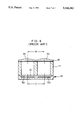
- FIG. 8 shows a conventional integral range finding device as a unit.
- Lens sections 3a and 3b are integrally formed on a transparent acrylic resin lens plate 10 at positions spaced by a lens base length B.
- a lens holder or housing 11 has two tunnels of a quadrangle in section and is made of black colored plastics.
- the lens plate 10 is fixed with adhesive agent in the state of high positioning precision.
- an IC package 13 is fixed with adhesive agent.
- This IC package 13 has image sensors 5a and 5b covered with a cover glass 12. Reference pixels of the image sensors 5a and 5b are disposed spaced apart by a sensor base length C which is set equal to the lens base length B.
- the lens base length B representing the distance between the optical axes of the lens sections 3a and 3b be quite the same as the sensor base length C representing the distance between the reference pixels of the image sensors 5a and 5b.
- the lens plate 10, lens holder 11, and the silicon substrate forming the image sensors 5a and 5b expand or contract differently from each other at given temperature and humidity. Therefore, the spherical surfaces of the lens sections 3a and 3b may be deformed by a force caused by a difference of expansion or contraction between the lens plate 10 and lens holder 11.
- each element changes its mounting position as temperature or humidity changes, resulting in a relative change between the lens base length B and the sensor base length C.
- the sensor base length C changes less with environmental conditions.
- resin is often used as the raw material of the lens holder 11 and lens plate 10, so that the lens base length B is likely to change greatly.
- a relative change between the lens base length B and sensor base length C is a main factor of distance measuring error, unable to maintain a reliable measurement precision.
- a range finding device comprising a lens holder having two light paths, and two lenses mounted in front of the lens holder.
- the lens holder is provided with two positioning members along two positioning lines extending in the direction perpendicular to the base line and traversing the light paths. Each lens is engaged with the lens holder in front of the light paths by means of the two positioning members.
- each positioning line is determined outwardly of a line passing the lens optical axis and extending in the direction perpendicular to the base line.
- a pin is used as the positioning member.
- Each lens has two holes into which pins are inserted.
- the two holes of each lens are preferably two elongated holes, or one elongated hole and one round hole. The dimension of the round hole is determined such that it allows tight fitting with the pin.
- the elongated hole extends in the positioning line direction.
- each lens is formed in each lens. Two of the four holes engage with two pins.
- the same mold can be used for manufacturing a pair of two lenses, allowing to manufacture two lenses having quite the same lens characteristics.
- the mounting posture of each lens is limited to one type, improving the efficiency of assembly work.
- a pair of lenses is correctly positioned in the base line direction, and has some play in the direction perpendicular to the base line.
- the lenses move with respect to the pin as fulcrum without being displaced by the lens holder in the base line direction, and freely move in the direction perpendicular to the base line without being displaced by the two pins.
- any external force will not be applied to the lens spherical surfaces.
- the coupling points between the lenses and lens holder are set in the outside of the range of the base length. It is therefore possible to cancel out the expansion or contraction between the lens holder and lenses, to accordingly prevent a displacement of the lens base length to be caused by a change of environmental conditions, and to maintain stable measurement precision.
- FIG. 1 is a perspective and broken view of an embodiment of a passive type range finding unit
- FIG. 2 is a vertical section of the range finding unit shown in FIG. 1;
- FIG. 3 is a front view of the range finding unit with an aperture cover being removed;
- FIG. 4 is a perspective and broken view of an active type range finding unit
- FIG. 5 is a perspective and broken view of another embodiment of the range finding unit according to the present invention.
- FIG. 6 is a front view of the range finding unit shown in FIG. 5;
- FIG. 7 is a schematic view showing a conventional autofocus system.
- FIG. 8 is a vertical section of a conventional range finding unit.
- a range finding unit comprises an IC package 20, a lens holder 21, a pair of lens plates 22 and 23, and an aperture cover 24.
- the IC package 20 has a silicon substrate and a transparent cover glass 20b attached to the front surface of the substrate, the substrate and the cover glass 20b being packaged with ceramics.
- the silicon substrate has a sensor chip 20a and a processing circuit 6 (refer to FIG. 7) formed by integration technique.
- the sensor chip 20a has a plurality of pixels for converting light into electrical signals. These pixels are linearly disposed at a constant pitch.
- Reference numeral 20c represents terminal pins of the IC package.
- the lens holder 21 formed of a box shape is made of black colored polycarbonate in mixture with glass fibers.
- the lens holder 21 has two tunnels 21f and 21g of a square shape in cross section, the two tunnels being used as light paths.
- the IC package 20 is fixed e.g. with adhesive agent.
- Lens positioning pins 21a to 21d are integrally formed on the front surface of the lens holder 21, and two hooks 21e are formed at the opposite side faces thereof.
- the pins 21a and 21b, and pins 21c and 21d are positioned symmetrically with a vertical center line of the lens holder 21, and outside of the range of a lens base line having a length B, i.e., outside of vertical center lines VL of the tunnels 21f and 21g.
- a lens base line having a length B i.e., outside of vertical center lines VL of the tunnels 21f and 21g.
- the distance D between each pin and a vertical center line of the lens holder 21 is about 7 mm.
- the lens plates 22 and 23 are formed by molding transparent acrylic resin. Lens sections 22c and 23c are formed at the central areas in a flat portion of the plates. The lens sections 22c and 23c have the same focal length. Elongated holes 22a and 22b are formed in the flat portion of the lens plate 22, the positioning pins 21a and 21b being inserted into the elongated holes 22a and 22b. The elongated holes 22a and 22b extend in the vertical direction, and the widths thereof in the base line direction are substantially the same as the outer diameters of the pins 21a and 21b. Similarly, elongated holes 23a and 23b are formed in the lens plate 23, the pins 21c and 21d being inserted in the elongated holes 23a and 23b.
- the aperture cover 24 formed of a channel shape is made of black colored plastics or black painted metal plate.
- the aperture cover 24 has two openings 24a and 24b facing the lens sections 22c and 23c.
- the aperture cover 24 is placed over the lens plates 22 and 23 so as to cover them.
- the aperture cover 24 is fixed to the lens holder 21 by engaging the hooks 21 with holes 24c, to squeeze the lens plates 22 and 23 therebetween and prevent displacement thereof to be caused by vibrations and shocks.
- the lens plates 22 and 23 are bonded to the front surface of the lens holder 21 by means of pressure-sensitive adhesive agent 26 having stickiness at an ordinary temperature.
- the distance between the optical axis P1 of the lens section 22c and the optical axis P2 of the lens section 23c can be definitely determined, providing a lens base length B shown in FIG. 2.
- This lens base length B is equal to the distance between reference pixels of the sensor chip 20a, i.e., a sensor base length C.
- the sensor base length C is defined during the assembly process of the range finding unit in accordance with the results of measuring a test subject. Thus, after the assembly adjustment, the sensor base length C becomes always equal to the lens base length B. So long as the lens base length B equals to the sensor base length C, the measurement precision will not be degraded.
- the sensor chip 20a is not separated into two parts for the two lens plates 22 and 23, unlike the case shown in FIGS. 7 and 8.
- This sensor chip 20a substantially functions as two line image sensors by dividing a photoelectrically converted signal from the sensor chip 20a into two parts.
- two images of a subject are focussed on the sensor chip 20a via the lens sections 22c and 23c.
- electrical signals for the two images are compared to calculate a subject distance.
- Signals representing the subject distance are sent to a lens drive circuit via the terminal pins 20c.
- adhesive agent is caused to coat the front surface of the lens holder 21 to attach the lens plates 22 and 23 to the front surface of the lens holder 21.
- the pins 21a and 21b are inserted into the elongated holes 22a and 22b of the lens plate 22, and the pins 21c and 21d are inserted into the elongated holes 23a and 23b of the lens plate 23.
- the lens plates 22 and 23 are slid in the direction of the vertical center lines VL so as to align the lens optical axes P1 and P2 with the centers of the tunnels 21f and 21g.
- the lens plates 22 and 23 are movably attached to the lens holder 21 by the pressure-sensitive adhesive agent 26, the positions of the lens plates 22 and 23 can be finely adjusted easily.
- the IC package 20 is fixed to the back surface of the lens holder 21 with adhesive agent. Then, range finding is carried out as to a test subject to determine two reference pixels.
- the lens base length B and sensor base length C are generally the same, allowing a high precision measurement. If the temperature and humidity are different from those at the time of assembly adjustment, the lens holder 21 and lens plates 22 and 23 expand or contract. With respect to the direction along the base line, the lens plates 22 and 23 can be expanded or contracted horizontally from the elongated holes without being displaced by the pins. With respect to the direction vertical to the base line, the lens plates 22 and 23 are allowed to be expanded or contracted freely in engagement of the elongated holes with the pins. No bending or contortion due to a stress in thermal deformation will take place in the lens plates 22 and 23.
- the lens plate 22 expands, the distance S between the elongated holes 22a and 22b and the optical axis P1 of the lens section 22c changes to "S+ ⁇ S" and the optical axis P1 of the lens section 22c moves to the right by ⁇ S because in this case the origin of expansion is considered as the elongated holes 22a and 22b.
- the lens base length B is kept unchanged even in expansion of the lens holder 21 and the lens plate 22, so that range finding is performed free from influence of the environmental conditions.
- the sensor chip 20a is also expanded or contracted so that the sensor base length C changes.
- a balancing condition is now taken into account such that no deviation takes place between the sensor base length C and the lens base length B.
- Equation 1 the value D is expressed by the following Equation 1:
- the coefficient ⁇ H is 3 ⁇ 10 -5 as the lens holder 21 is made of polycarbonate in mixture with 30% glass fibers
- the coefficient ⁇ L is 9 ⁇ 10 -5 as the lens plates 22 and 23 are made of acrylic resin
- the coefficient ⁇ S is 0.25 ⁇ 10 -5 as the sensor chip 20a is made of silicon.
- the value D is set to 7.15 mm at the environmental temperature at the time of assembly adjustment, e.g., at a room temperature, no displacement between the lens base length B and sensor base length C will take place and the range finding performance expected at the time of designing can be maintained, even if the components of the range finding unit are subject to thermal expansion due to temperature change.
- the lens holder 21 and lens plates 22 and 23 also expand in the direction perpendicular to the direction of the lens base line.
- the elongated holes 22a, 22b, 23a, and 23b provide some play to the pins 21a to 21d. Therefore, even the lens plates 22 and 23 expand, they are not resistive against the pins. Furthermore, even if the optical axes P1 and P2 of the lens plates 22 and 23 move in the direction perpendicular to the lens base line, there is not practical problem as to the measurement precision.
- Equation 2 the value D satisfying the following Equation 2 is selected, neglecting the hygroscopic expansion coefficient of the silicon chip 20a because it is very small:
- ⁇ L and ⁇ H are the hygroscopic expansion coefficients of the lens holder 21 and lens plates 22 and 23.
- the direction of expansion of the lens holder 21 and the direction of expansion of the lens plates 22 and 23 are made opposite to cancel out a change of the lens base length B due to expansion of the lens holder and lens plates, thereby preventing degradation of measurement precision caused by thermal expansion and hygroscopic expansion.
- a compensation for a change of the lens base length B can be made more reliable by determining the mounting positions of the lens holder 21 and lens plates 22 and 23 while taking into consideration both the thermal and hygroscopic expansion coefficients.
- poly-ethyl-ethylketone for example may be used as the material of the lens holder 21, with transparent polycarbonate being used as the material of the lens plates 22 and 23.
- a change of the lens base length B can be compensated relative to the sensor base length C, by simply forming elongated holes in the lens plates 22 and 23 on the lines perpendicular to the optical axes P1 and P2 and by coupling the lens holder 21 and lens plates 22 and 23 together at the positions of the elongated holes.
- One elongated hole and one round hole tightly fitted with a pin may be formed in the lens plate.
- two pins may be formed integrally on the lens plate and corresponding two holes may be formed in the lens holder.
- FIG. 4 shows an active type range finding unit. Like elements to the embodiment shown in FIG. 1 are represented by using identical reference numerals.
- An IC package 30 has a sensor chip 30a and an infrared light emitting diode 30b. The center of the sensor chip 30a is aligned or collinear with the optical axis P2 of the lens section 23c, and the center of the infrared light emitting diode 30b is aligned with the optical axis P1 of the lens section 22c.
- infrared light emitted from the infrared light emitting diode 30b is projected via the lens section 22c toward a subject.
- the infrared light reflected from the subject is incident to the sensor chip 30a via the lens section 23c.
- the subject distance is obtained from an incident position of the reflected light on to the sensor chip 30a, and a signal representing the obtained subject distance is outputted.
- the optical specifics of the two lens plates 22 and 23 are required to be the same to thereby obtain the same image. It is advantageous therefore to mold two lens plates 22 and 23 using the same mold.
- the two lens plates 22 and 23 manufactured using the same mold are mounted on the lens holder 21, it is necessary to mount the lens plate 23 upside down with respect to the lens plate 22. Therefore, if the lens plates 22 and 23 have a molding strain, for example, this strain is enhanced because of reversed mounting positions of the lens plates 22 and 23.
- the two images focussed on the chip sensor 20a differ greatly, degrading the measurement precision to a large extent.
- FIGS. 5 and 6 show an embodiment allowing to mount two lens plates manufactured using the same mold on a lens holder without placing upside down one of the two lens plates with respect to the other.
- a lens plate 32 has a lens section 32e and a flat area surrounding the lens section 32e.
- Two elongated holes 32a and 32b are formed in the upper portion of the flat area, and two round holes 32c and 32d are formed in the lower portion thereof.
- the elongated hole 32a and round hole 32c are formed on the line perpendicular to the lens base line, at the positions outwardly spaced apart by a distance S from a vertical center line VL, the other elongated hole 32b and round hole 32d being formed at the positions inwardly spaced apart by the distance from the vertical center line VL.
- the elongated hole 32a and round hole 32c are symmetrical with the elongated hole 32b and round hole 32d relative to the vertical center line VL.
- elongated holes 33a and 33b and round holes 33c and 33d are formed in the other lens plate 33.
- Pins 21a and 21b are inserted into the elongated hole 32a and round hole 32c of the lens plate 32 to hold it in position, without using the elongated hole 32b and round hole 32d.
- Pins 21c and 21d are fitted in the elongated hole 33b and round hole 33d of the lens plate 33 to hold it in position, without using the elongated hole 33a and round hole 33c.
- the two elongated holes and two round holes are formed in each lens plate manufactured by using the same mold, symmetrically with the vertical center line VL. Therefore, it is not necessary to place upside down one of the two lens plates in mounting them on the lens holder 21. If a molding strain is present on the lens plates, the influence of this strain comes into existence on the focussing plane quite the same as to the direction of the lens base line, without causing any measurement error in range finding.
- the lens plates 32 and 33 if each lens plate is held so as to face the elongated holes 32a and 32b toward the upper side of the horizontal center line HL and face the round holes 32c and 32d toward the lower side, the mounting work will not be misguided.
- the lens plates 32 and 33 When the lens plates 32 and 33 expand by temperature or humidity, they expand also in the direction perpendicular to the lens base line. In this case, there is some play between the pins 21a and 21c and the elongated holes 32a and 33b, so that the lens plates 32 and 33 expand relative to the joints between the other pins 21b and 21d and the round holes 32c and 33d. As a result, when the lens plates 32 and 33 expand in the direction perpendicular to the lens base line, they are not susceptible to resistance by the pins 21a and 21c, preventing the spherical deformation of the lens sections 32e and 33e.
- each of the lens plates 32 and 33 has four round holes.
- four elongated holes may be formed in each of the lens plates 32 and 33.
- the IC package 20 may be mounted spaced apart from the back surface of the lens holder 21.
- other coupling elements may also be used, which have play in the direction perpendicular to the base line, such as protrusions and grooves, steps and other receiving steps, and the like.
- two solid blocks bonded together may be used, the blocks being made of transparent resin or glass for example, with its outer periphery except the front and back surfaces being light shielded.
Abstract
Description
L=(B×F)/X
D×α.sub.H -S×α.sub.L =B/2×α.sub.S
D=B/2×(α.sub.L -α.sub.S)/(α.sub.L -α.sub.H)
D=B/2×β.sub.L /(β.sub.L -β.sub.H)
Claims (21)
Applications Claiming Priority (4)
| Application Number | Priority Date | Filing Date | Title |
|---|---|---|---|
| JP9824591A JP2880821B2 (en) | 1991-04-03 | 1991-04-03 | Optical module for distance measurement |
| JP3098236A JPH04228158A (en) | 1990-04-03 | 1991-04-03 | Actuator-locking device for magnetic head |
| JP3-98245 | 1991-04-03 | ||
| JP3-98236 | 1991-04-03 |
Publications (1)
| Publication Number | Publication Date |
|---|---|
| US5233382A true US5233382A (en) | 1993-08-03 |
Family
ID=26439435
Family Applications (1)
| Application Number | Title | Priority Date | Filing Date |
|---|---|---|---|
| US07/862,177 Expired - Lifetime US5233382A (en) | 1991-04-03 | 1992-04-02 | Range finding device unaffected by environmental conditions |
Country Status (1)
| Country | Link |
|---|---|
| US (1) | US5233382A (en) |
Cited By (24)
| Publication number | Priority date | Publication date | Assignee | Title |
|---|---|---|---|---|
| US5488468A (en) * | 1991-12-26 | 1996-01-30 | Sharp Kabushiki Kaisha | Optical distance measuring apparatus having semiconductor position sensitive photodetector |
| US5659815A (en) * | 1993-03-15 | 1997-08-19 | Nikon Corporation | Focus detection device |
| US5745805A (en) * | 1993-05-14 | 1998-04-28 | Olympus Optical Co., Ltd. | Focus detecting device |
| US5815747A (en) * | 1995-12-28 | 1998-09-29 | Olympus Optical Co., Ltd. | Camera having autofocus function independent of photographing optical system |
| US5959724A (en) * | 1997-01-09 | 1999-09-28 | Fuji Electric Co., Ltd. | Distance measuring apparatus |
| US6046795A (en) * | 1998-01-28 | 2000-04-04 | Fuji Electric Co., Ltd. | Distance measuring instrument |
| US6067147A (en) * | 1997-01-09 | 2000-05-23 | Fuji Electric Co., Ltd. | Distance-measuring apparatus |
| US20030086193A1 (en) * | 1999-12-09 | 2003-05-08 | Contraves Space Ag | Optical unit and its use |
| US20040061848A1 (en) * | 2002-08-08 | 2004-04-01 | Shiroshi Kanemitsu | Angle detecting apparatus and projector having the same |
| US20080001727A1 (en) * | 2004-11-15 | 2008-01-03 | Hitachi, Ltd. | Stereo Camera |
| US20100025122A1 (en) * | 2008-08-04 | 2010-02-04 | Cho-Yi Lin | Image-Sensing Module and Image-Sensing System |
| WO2010022664A1 (en) * | 2008-08-28 | 2010-03-04 | 上海科勒电子科技有限公司 | Distance detection induction device |
| US20100073668A1 (en) * | 2008-09-23 | 2010-03-25 | Hon Hai Precision Industry Co., Ltd. | Lens screening device |
| US20100110413A1 (en) * | 2008-11-05 | 2010-05-06 | Liu Xingyan | Distance detecting sensor and close range detecting method |
| US20100258711A1 (en) * | 2009-04-13 | 2010-10-14 | Jianhua Wang | Photoelectric Sensor |
| US20110024627A1 (en) * | 2009-07-31 | 2011-02-03 | Avago Technologies Ecbu (Singapore) Pte. Ltd. | Proximity Sensor with Ceramic Housing and Light Barrier |
| US20110050855A1 (en) * | 2006-07-26 | 2011-03-03 | Guenter Nobis | Optical measuring device with two camera units |
| CN103282740A (en) * | 2010-12-28 | 2013-09-04 | 株式会社理光 | Ranging apparatus |
| WO2013149852A1 (en) * | 2012-04-04 | 2013-10-10 | Valeo Schalter Und Sensoren Gmbh | Optoelectronic sensor device, particularly laser scanner, with an adapted receiving unit for optimized reception level reduction |
| US20130327930A1 (en) * | 2012-06-11 | 2013-12-12 | Mitutoyo Corporation | Optical encoder and lens fixing mechanism thereof |
| WO2016123878A1 (en) * | 2015-02-03 | 2016-08-11 | 金华马卡科技有限公司 | Handheld rangefinder |
| CN105954738A (en) * | 2016-06-28 | 2016-09-21 | 北醒(北京)光子科技有限公司 | Direct-driven small rotary scanning distance measuring device |
| CN106679573A (en) * | 2017-03-10 | 2017-05-17 | 柳州科路测量仪器有限责任公司 | Light curtain measurement transceiver focusing lens locking device |
| USD805078S1 (en) * | 2015-05-07 | 2017-12-12 | Datalogic Ip Tech S.R.L. | Barcode reading module |
Citations (1)
| Publication number | Priority date | Publication date | Assignee | Title |
|---|---|---|---|---|
| US4828383A (en) * | 1985-11-11 | 1989-05-09 | Olympus Optical Co., Ltd. | Range-finding optical system |
-
1992
- 1992-04-02 US US07/862,177 patent/US5233382A/en not_active Expired - Lifetime
Patent Citations (1)
| Publication number | Priority date | Publication date | Assignee | Title |
|---|---|---|---|---|
| US4828383A (en) * | 1985-11-11 | 1989-05-09 | Olympus Optical Co., Ltd. | Range-finding optical system |
Cited By (45)
| Publication number | Priority date | Publication date | Assignee | Title |
|---|---|---|---|---|
| US5488468A (en) * | 1991-12-26 | 1996-01-30 | Sharp Kabushiki Kaisha | Optical distance measuring apparatus having semiconductor position sensitive photodetector |
| US5659815A (en) * | 1993-03-15 | 1997-08-19 | Nikon Corporation | Focus detection device |
| US5745805A (en) * | 1993-05-14 | 1998-04-28 | Olympus Optical Co., Ltd. | Focus detecting device |
| US5815747A (en) * | 1995-12-28 | 1998-09-29 | Olympus Optical Co., Ltd. | Camera having autofocus function independent of photographing optical system |
| US6215959B1 (en) | 1995-12-28 | 2001-04-10 | Olympus Optical Co., Ltd. | Camera having autofocus function independent of photographing optical system |
| US5959724A (en) * | 1997-01-09 | 1999-09-28 | Fuji Electric Co., Ltd. | Distance measuring apparatus |
| US6067147A (en) * | 1997-01-09 | 2000-05-23 | Fuji Electric Co., Ltd. | Distance-measuring apparatus |
| US6046795A (en) * | 1998-01-28 | 2000-04-04 | Fuji Electric Co., Ltd. | Distance measuring instrument |
| KR100538900B1 (en) * | 1998-01-28 | 2005-12-27 | 후지 덴키 가부시끼가이샤 | Distance-measuring instrument |
| US6795260B2 (en) * | 1999-12-09 | 2004-09-21 | Contraves Space Ag | Optical unit and its use |
| US20030086193A1 (en) * | 1999-12-09 | 2003-05-08 | Contraves Space Ag | Optical unit and its use |
| US20040061848A1 (en) * | 2002-08-08 | 2004-04-01 | Shiroshi Kanemitsu | Angle detecting apparatus and projector having the same |
| US7042560B2 (en) * | 2002-08-08 | 2006-05-09 | Seiko Precision Inc. | Angle detecting apparatus and projector having the same |
| US20080001727A1 (en) * | 2004-11-15 | 2008-01-03 | Hitachi, Ltd. | Stereo Camera |
| US9456199B2 (en) | 2004-11-15 | 2016-09-27 | Hitachi, Ltd. | Stereo camera |
| US20110050855A1 (en) * | 2006-07-26 | 2011-03-03 | Guenter Nobis | Optical measuring device with two camera units |
| US20100025122A1 (en) * | 2008-08-04 | 2010-02-04 | Cho-Yi Lin | Image-Sensing Module and Image-Sensing System |
| WO2010022664A1 (en) * | 2008-08-28 | 2010-03-04 | 上海科勒电子科技有限公司 | Distance detection induction device |
| US8766195B2 (en) * | 2008-08-28 | 2014-07-01 | Shanghai Kohler Electronics Ltd. | Distance detection induction device |
| US20120298872A1 (en) * | 2008-08-28 | 2012-11-29 | Qiaomei Tang | Distance detection induction device |
| US20100073668A1 (en) * | 2008-09-23 | 2010-03-25 | Hon Hai Precision Industry Co., Ltd. | Lens screening device |
| US8018583B2 (en) * | 2008-09-23 | 2011-09-13 | Hon Hai Precision Industry Co., Ltd. | Lens screening device |
| US8212994B2 (en) | 2008-11-05 | 2012-07-03 | Shanghai Kohler Electronics, Ltd. | Distance detecting sensor and close range detecting method |
| US20100110413A1 (en) * | 2008-11-05 | 2010-05-06 | Liu Xingyan | Distance detecting sensor and close range detecting method |
| US8576384B2 (en) | 2008-11-05 | 2013-11-05 | Shanghai Kohler Electronics, Ltd. | Distance detecting sensor and close range detecting method |
| US8487235B2 (en) * | 2009-04-13 | 2013-07-16 | Rockwell Automation Technologies, Inc. | Photoelectric sensor for sensing a target at a predetermined location |
| US20100258711A1 (en) * | 2009-04-13 | 2010-10-14 | Jianhua Wang | Photoelectric Sensor |
| US20110024627A1 (en) * | 2009-07-31 | 2011-02-03 | Avago Technologies Ecbu (Singapore) Pte. Ltd. | Proximity Sensor with Ceramic Housing and Light Barrier |
| CN103282740B (en) * | 2010-12-28 | 2015-12-09 | 株式会社理光 | Distance-measuring equipment |
| CN103282740A (en) * | 2010-12-28 | 2013-09-04 | 株式会社理光 | Ranging apparatus |
| US9429423B2 (en) | 2010-12-28 | 2016-08-30 | Ricoh Company, Ltd. | Ranging apparatus |
| CN104272133B (en) * | 2012-04-04 | 2017-12-12 | 法雷奥开关和传感器有限责任公司 | The optoelectronic sensor device of adaptability receiving unit with the horizontal reduction of reception for optimization, particularly laser scanner |
| KR20150002741A (en) * | 2012-04-04 | 2015-01-07 | 발레오 샬터 운트 센소렌 게엠베아 | Optoelectronic sensor device, particularly laser scanner, with an adapted receiving unit for optimized reception level reduction |
| US9606222B2 (en) | 2012-04-04 | 2017-03-28 | Valeo Schalter Und Sensoren Gmbh | Optoelectronic sensor device, in particular laser scanner, having an adapted receiving unit for optimized reduction of the reception level |
| CN104272133A (en) * | 2012-04-04 | 2015-01-07 | 法雷奥开关和传感器有限责任公司 | Optoelectronic sensor device, particularly laser scanner, with an adapted receiving unit for optimized reception level reduction |
| WO2013149852A1 (en) * | 2012-04-04 | 2013-10-10 | Valeo Schalter Und Sensoren Gmbh | Optoelectronic sensor device, particularly laser scanner, with an adapted receiving unit for optimized reception level reduction |
| US20130327930A1 (en) * | 2012-06-11 | 2013-12-12 | Mitutoyo Corporation | Optical encoder and lens fixing mechanism thereof |
| US9097560B2 (en) * | 2012-06-11 | 2015-08-04 | Mitutoyo Corporation | Optical encoder including scale having track and detection head for detecting the track |
| CN103487075A (en) * | 2012-06-11 | 2014-01-01 | 株式会社三丰 | Optical encoder and lens fixing mechanism thereof |
| WO2016123878A1 (en) * | 2015-02-03 | 2016-08-11 | 金华马卡科技有限公司 | Handheld rangefinder |
| USD805078S1 (en) * | 2015-05-07 | 2017-12-12 | Datalogic Ip Tech S.R.L. | Barcode reading module |
| USD830362S1 (en) | 2015-05-07 | 2018-10-09 | Datalogic Ip Tech S.R.L. | Barcode reading module |
| CN105954738A (en) * | 2016-06-28 | 2016-09-21 | 北醒(北京)光子科技有限公司 | Direct-driven small rotary scanning distance measuring device |
| CN105954738B (en) * | 2016-06-28 | 2018-06-08 | 北醒(北京)光子科技有限公司 | A kind of straight small rotary that drives scans range unit |
| CN106679573A (en) * | 2017-03-10 | 2017-05-17 | 柳州科路测量仪器有限责任公司 | Light curtain measurement transceiver focusing lens locking device |
Similar Documents
| Publication | Publication Date | Title |
|---|---|---|
| US5233382A (en) | Range finding device unaffected by environmental conditions | |
| JP4378434B2 (en) | Compound eye camera module | |
| US20030137595A1 (en) | Image pickup device and camera | |
| US5917976A (en) | Optical transmission path coupling method and optical transmission path coupling apparatus as well as optical axis self-alignment tool | |
| KR100538900B1 (en) | Distance-measuring instrument | |
| KR100556198B1 (en) | Solid state imaging device, method for producing the same, solid state imaging unit and method for producing the same, and imaging apparatus | |
| US9235014B2 (en) | Optics system module for use in an optical communications module, an optical communications system, and a method | |
| US20100259655A1 (en) | Imaging device | |
| US7554677B2 (en) | Optical measuring device for measuring micro displacement or micro vibration of object | |
| US20070097249A1 (en) | Camera module | |
| JP2012150093A (en) | Distance measuring device | |
| US6414299B1 (en) | Method of mounting optical sensor package | |
| US4662735A (en) | Plastic lens elements supporting structure | |
| JP2001116962A (en) | Optical element array module and its manufacturing method | |
| JP2779585B2 (en) | Imaging device | |
| JP2880821B2 (en) | Optical module for distance measurement | |
| JP2724251B2 (en) | Positioning method of distance measuring lens | |
| US4470682A (en) | Optical element positioning method and optical element assembly utilizing the same | |
| JP2597974B2 (en) | Mounting device for solid-state imaging device | |
| JPH0974523A (en) | Attaching method for image pickup ccd and ccd camera | |
| KR101944943B1 (en) | Optical transmitting and receiving module and manual alignment method thereof | |
| US5033844A (en) | Camera employing automatic focusing unit | |
| US5659815A (en) | Focus detection device | |
| JPS61165711A (en) | Plastic lens fixing structure | |
| JPH09318867A (en) | Range finder for camera |
Legal Events
| Date | Code | Title | Description |
|---|---|---|---|
| AS | Assignment |
Owner name: FUJI PHOTO FILM COMPANY, LIMITED, JAPAN Free format text: ASSIGNMENT OF ASSIGNORS INTEREST.;ASSIGNORS:TANIGUCHI, ISAO;KAWAJIRI, KAZUHIRO;TAMURA, HIROSHI;REEL/FRAME:006174/0630 Effective date: 19920618 |
|
| STCF | Information on status: patent grant |
Free format text: PATENTED CASE |
|
| CC | Certificate of correction | ||
| FPAY | Fee payment |
Year of fee payment: 4 |
|
| FPAY | Fee payment |
Year of fee payment: 8 |
|
| FEPP | Fee payment procedure |
Free format text: PAYOR NUMBER ASSIGNED (ORIGINAL EVENT CODE: ASPN); ENTITY STATUS OF PATENT OWNER: LARGE ENTITY |
|
| FPAY | Fee payment |
Year of fee payment: 12 |
|
| AS | Assignment |
Owner name: FUJIFILM HOLDINGS CORPORATION, JAPAN Free format text: CHANGE OF NAME;ASSIGNOR:FUJI PHOTO FILM CO., LTD.;REEL/FRAME:018898/0872 Effective date: 20061001 Owner name: FUJIFILM HOLDINGS CORPORATION,JAPAN Free format text: CHANGE OF NAME;ASSIGNOR:FUJI PHOTO FILM CO., LTD.;REEL/FRAME:018898/0872 Effective date: 20061001 |
|
| AS | Assignment |
Owner name: FUJIFILM CORPORATION, JAPAN Free format text: ASSIGNMENT OF ASSIGNORS INTEREST;ASSIGNOR:FUJIFILM HOLDINGS CORPORATION;REEL/FRAME:018934/0001 Effective date: 20070130 Owner name: FUJIFILM CORPORATION,JAPAN Free format text: ASSIGNMENT OF ASSIGNORS INTEREST;ASSIGNOR:FUJIFILM HOLDINGS CORPORATION;REEL/FRAME:018934/0001 Effective date: 20070130 |