US5209378A - Liquid aerating apparatus - Google Patents
Liquid aerating apparatus Download PDFInfo
- Publication number
- US5209378A US5209378A US07/746,113 US74611391A US5209378A US 5209378 A US5209378 A US 5209378A US 74611391 A US74611391 A US 74611391A US 5209378 A US5209378 A US 5209378A
- Authority
- US
- United States
- Prior art keywords
- bottle
- receiving means
- valve
- plunger
- pressure
- Prior art date
- Legal status (The legal status is an assumption and is not a legal conclusion. Google has not performed a legal analysis and makes no representation as to the accuracy of the status listed.)
- Expired - Lifetime
Links
Images


Classifications
-
- A—HUMAN NECESSITIES
- A47—FURNITURE; DOMESTIC ARTICLES OR APPLIANCES; COFFEE MILLS; SPICE MILLS; SUCTION CLEANERS IN GENERAL
- A47J—KITCHEN EQUIPMENT; COFFEE MILLS; SPICE MILLS; APPARATUS FOR MAKING BEVERAGES
- A47J31/00—Apparatus for making beverages
-
- B—PERFORMING OPERATIONS; TRANSPORTING
- B67—OPENING, CLOSING OR CLEANING BOTTLES, JARS OR SIMILAR CONTAINERS; LIQUID HANDLING
- B67D—DISPENSING, DELIVERING OR TRANSFERRING LIQUIDS, NOT OTHERWISE PROVIDED FOR
- B67D1/00—Apparatus or devices for dispensing beverages on draught
- B67D1/08—Details
- B67D1/12—Flow or pressure control devices or systems, e.g. valves, gas pressure control, level control in storage containers
- B67D1/125—Safety means, e.g. over-pressure valves
-
- B—PERFORMING OPERATIONS; TRANSPORTING
- B01—PHYSICAL OR CHEMICAL PROCESSES OR APPARATUS IN GENERAL
- B01F—MIXING, e.g. DISSOLVING, EMULSIFYING OR DISPERSING
- B01F23/00—Mixing according to the phases to be mixed, e.g. dispersing or emulsifying
- B01F23/20—Mixing gases with liquids
- B01F23/23—Mixing gases with liquids by introducing gases into liquid media, e.g. for producing aerated liquids
- B01F23/236—Mixing gases with liquids by introducing gases into liquid media, e.g. for producing aerated liquids specially adapted for aerating or carbonating beverages
- B01F23/2361—Mixing gases with liquids by introducing gases into liquid media, e.g. for producing aerated liquids specially adapted for aerating or carbonating beverages within small containers, e.g. within bottles
-
- B—PERFORMING OPERATIONS; TRANSPORTING
- B01—PHYSICAL OR CHEMICAL PROCESSES OR APPARATUS IN GENERAL
- B01F—MIXING, e.g. DISSOLVING, EMULSIFYING OR DISPERSING
- B01F33/00—Other mixers; Mixing plants; Combinations of mixers
- B01F33/50—Movable or transportable mixing devices or plants
- B01F33/501—Movable mixing devices, i.e. readily shifted or displaced from one place to another, e.g. portable during use
- B01F33/5014—Movable mixing devices, i.e. readily shifted or displaced from one place to another, e.g. portable during use movable by human force, e.g. kitchen or table devices
-
- B—PERFORMING OPERATIONS; TRANSPORTING
- B01—PHYSICAL OR CHEMICAL PROCESSES OR APPARATUS IN GENERAL
- B01F—MIXING, e.g. DISSOLVING, EMULSIFYING OR DISPERSING
- B01F35/00—Accessories for mixers; Auxiliary operations or auxiliary devices; Parts or details of general application
- B01F35/60—Safety arrangements
-
- B—PERFORMING OPERATIONS; TRANSPORTING
- B67—OPENING, CLOSING OR CLEANING BOTTLES, JARS OR SIMILAR CONTAINERS; LIQUID HANDLING
- B67D—DISPENSING, DELIVERING OR TRANSFERRING LIQUIDS, NOT OTHERWISE PROVIDED FOR
- B67D1/00—Apparatus or devices for dispensing beverages on draught
- B67D1/04—Apparatus utilising compressed air or other gas acting directly or indirectly on beverages in storage containers
- B67D1/0406—Apparatus utilising compressed air or other gas acting directly or indirectly on beverages in storage containers with means for carbonating the beverage, or for maintaining its carbonation
-
- B—PERFORMING OPERATIONS; TRANSPORTING
- B67—OPENING, CLOSING OR CLEANING BOTTLES, JARS OR SIMILAR CONTAINERS; LIQUID HANDLING
- B67D—DISPENSING, DELIVERING OR TRANSFERRING LIQUIDS, NOT OTHERWISE PROVIDED FOR
- B67D1/00—Apparatus or devices for dispensing beverages on draught
- B67D1/08—Details
- B67D1/12—Flow or pressure control devices or systems, e.g. valves, gas pressure control, level control in storage containers
Definitions
- This invention relates to apparatus for aerating liquids, and in particular to portable machines for preparing aerated beverages. More especially, the invention concerns such machines intended for use in the home and adapted to be operated manually.
- a bottle containing the liquid to be aerated is loaded onto the machine and gas is introduced into the machine and passed through the liquid contained in the bottle. The bottle is subsequently removed, when the aerating has been completed.
- the gas used for aerating is supplied from a cylinder fitted to the machine, which is replaced when it has become exhausted.
- a valve is provided to control the flow of gas from the cylinder, which, in the case of rechargeable cylinders, may form part of the cylinder, or in the case of disposable cylinders may form part of the machine.
- gas may pass into the machine and through the liquid, generating an internal pressure inside the machine and bottle, which is limited to a given maximum level by a pressure relief and safety valve.
- the pressure inside the machine and bottle is reduced to atmospheric level by opening a valve.
- the liquid aerating apparatus is characterized in that it comprises safety means for detecting any irregularity in the shape and/or dimensions of the bottle and preventing undesired pressurization of a bottle having such irregularities.
- the said safety means comprise means for releasing the pressure in the apparatus and in the bottle if the bottle acquires shape and/or dimension irregularities as a result of expansion during the aeration.
- the said safety means comprise means for preventing the formation of pressure in a bottle which presents shape and or dimension irregularities.
- the liquid aerating apparatus is provided with a reference surface, means for causing a bottle loaded on the apparatus to come into matching relationship with the reference surface, and means for preventing the build-up of pressure or releasing the pressure in the bottle, if the position of the bottle, when in such a relationship with the reference surface, does not correspond to the position of a bottle having the correct shape and dimensions.
- said matching relationship is achieved through direct contact of the bottle with the reference surface, but it could be achieved otherwise, by providing any suitable intermediate elements between the bottle surface and the reference surface, or by using position comparator means or scanning means comparing the bottle profile with the reference surface, or the like.
- means for causing the bottle to come into contact with the reference surface comprise means for receiving the bottle in removable engagement, said bottle receiving means comprising means for allowing the engaged bottle to become displaced towards the reference surface and abut against the same by gravity.
- the last mentioned means comprise a pivot coupling between said bottle receiving means and support means rigid with the body of the apparatus, said receiving means being so structured that the cumulative centre of gravity of the bottle and the bottle receiving means, when they are mutually engaged, is offset with respect to the centre of said pivot coupling, whereby to cause the weight of the bottle to urge the same towards the reference surface.
- the apparatus comprises at least a valve for placing the bottle and the parts of the apparatus communicating therewith in the pressurizing operation in communication with the atmosphere, when open, and means for causing said valve to be open when the axis of the bottle is not in the position in which the axis of a bottle having the standard, correct shape and size is, when such a bottle abuts against the reference surface.
- Said position will be called hereinafter, for brevity's sake, "the correct position”.
- the corresponding position of said receiving means will likewise be called “the correct position of the receiving means”.
- the correct position actually embraces a range of positions, expressing a degree of tolerance, about an ideal one.
- the means for causing said valve to be open comprise a plunger for displacing the valve closure element from its seat and cam means fixedly carried by the apparatus frame and so shaped as to actuate said plunger when the bottle axis, and consequently the receiving means, are angularly displaced from the respective correct position.
- the minimum displacement angle that will cause the cam to actuate the plunger should preferably correspond to a linear displacement of the contact point of the plunger with the cam, along the surface of said cam, of at most a few millimeters, e.g.
- valves are provided in the apparatus, both of which operate as venting valves to release pressure, even if the bottle is in its correct position, when the pressure has reached a certain threshold value, which is preferably different for the two valves, the lower value corresponding to the completion of the aerating, and both of which are cam-actuated as safety valves to release any pressure, even below the threshold value, which may exist, or prevent the creation of a pressure, when the bottle is displaced from the correct position.
- a certain threshold value which is preferably different for the two valves, the lower value corresponding to the completion of the aerating, and both of which are cam-actuated as safety valves to release any pressure, even below the threshold value, which may exist, or prevent the creation of a pressure, when the bottle is displaced from the correct position.
- the cams and other parts of the apparatus are so structured that the said valve or valves will operate to discharge pressure and/or to prevent pressure from being built up when the bottle axis and the receiving means are displaced from the respective correct positions in either direction, whereby bottles the diameters of which are below the correct values at any part of their contour will also not be pressurized.
- the apparatus comprises, in combination with hand-operatable means for placing a gas cylinder, loaded in it, in communication with the inside of a bottle also loaded in it, means for preventing said hand-operatable means from being actuated if the bottle axis and the bottle receiving means are not in the correct position, said last mentioned means permitting the safety valves to be actuated by a displacement of the bottle axis and bottle receiving means even if said hand-operatable means are being operated.
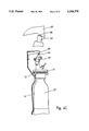
- FIG. 1 is a vertical view of an apparatus according to an embodiment of the invention, parts of it being in cross-section;
- FIG. 2 is a vertical cross-section at an enlarged scale of part of the apparatus of FIG. 1;
- FIG. 3 is a cross-section of a detail of FIG. 2, taken on the plane III--III of FIG. 2, looking in the direction of the arrows;
- FIG. 4 (a), (b) and (c) is a schematic illustration, in vertical view with details shown at an enlarged scale, of how a pressure release valve, according to an embodiment of the invention, is actuated to release pressure or prevent formation thereof when the bottle, which is in the apparatus, is not in the correct position.
- an apparatus comprises a main body generally indicated at 10.
- a bottle receiving means which is shown as an aerating head assembly 11, hinged on the body at 12 so as to be capable of being swung outwards (in counter-clockwise direction, as seen in FIG. 1) for insertion of a bottle indicated at 13.
- a bottle is fitted on said head assembly and released, it will swing back under its own weight, rotating about hinge 12, until it comes into contact with a surface 14, hereinafter called “reference surface”. This occurs because the center of gravity of the bottle and aerating assembly together is offset outwardly with respect to the pivot 12.
- the profile of the bottle is not as it should be, only parts thereof, particularly the parts that jut outwardly with respect to the ideal profile, will contact the surface 14.
- Other, direct or indirect, means could be provided by skilled persons for comparing the profile of the bottle with that of the reference surface, which could be mounted in the apparatus in a different position and in a different way, and for detecting any discrepancies between them.
- the bottle 13, containing liquid to be aerated is engaged with said head 11 and is held in engagement with the same by means of an external thread 15 provided on the bottle which engages an internal thread 16 provided in the head 11, or other suitable means, a flange 17 or like means being provided on the neck of the bottle for limiting the distance by which the bottle 13 screws into the aerating head assembly 11.
- an elastic gasket 18, preferably made of rubber and provided with a rigid stiffening sleeve 19, or like means with sufficient pressure to create a gas and fluid tight seal.
- a fluid or gas tight seal will not be effected, and the bottle will not become pressurized.
- the aerating head assembly 11 accommodates a tube 20 which extends through gasket 18, against which the mouth of the neck of the bottle 13 is engaged, and down inside the bottle 13. At its lower end the tube is threaded into a jet 21 which has a small bore 22 matching with the bore of said tube at 23.
- the aerating head 11 comprises an upper part 24 and a lower part 25, which is connected to the upper part in any suitable way, e.g. by means of screws 26.
- a suitable sealing means in this case a ring 27, which is part of the gasket 18, insures liquid and gas tight seal between the two parts of the aerating head 11.
- tube 20 is threaded at 28 into the upper part 24 of the aerating head 11 and communicates at its upper end with a passage or bore 29, which is connected to a flexible tube 30 by a connection 31, which ends in a bore 32 of a gas cylinder holder 33 and is held therein by a connector 34. Bore 32 in turn communicates with chamber 36 of cylinder holder 33.
- Cylinder holder 33 is threaded internally at 37 to receive an externally threaded boss 38 of a valve body 39 which is screwed at 40 onto the neck 41 of a small gas cylinder 42.
- the valve body 39 is part of a valve assembly 45 which is fitted on each gas cylinder 42, so that a used gas cylinder can be removed together with its valve assembly from the cylinder holder 33 and a fully charged cylinder with its own valve assembly 45 can be fitted in its place.
- the valve body 39 has a valve chamber 44 which houses a spring 43.
- the valve assembly 45 further comprises a valve pin 46 bonded to a gasket 47, which pin is urged by spring 43 against a seat formed at the lower end of an insert 49, which is provided with a bore through which a projection 50 of pin 46 passes.
- the cylinder holder 33 is fitted with a plunger 51 which can be depressed by an external, manually operated, swingable, finger-actuated lever 52, pivoted at 53 on said cylinder holder. Depression of lever 52 causes plunger 51 to slide downwards and press downwards projection 50 of valve pin 46, against the reaction of spring 43, whereby to permit gas to pass from cylinder 42 through the bore of insert 49 and into chamber 36 of the cylinder holder, therefrom through flexible tube 30 and then into tube 20 which extends downward into the bottle 13 containing the liquid to be aerated.
- the spring 43 reasserts itself to urge the valve pin 46 upwards against its seat and close the valve 45, concurrently returning the plunger 51 upwards to its starting position.
- the valve body 39 may be provided with a subsidiary safety device, such as a blow out disk 55 which acts to release excess pressure in the gas cylinder 42.
- the finger actuated lever 52 can be depressed when the aerating head 11 is in the vicinity of its fully swung downwards position, which is the aerating position. This is because the aerating head 11 is solid with a plate 56 which, as seen in FIG. 1, prohibits depression of lever 52 when it is swung away from the aerating position by an angle greater than a predetermined tolerance angle, as will be explained hereinafter, whereby to prevent undesirable or unsafe discharge of gas.
- the aerating head assembly 11 comprises an upper aerating head 24, fitted with a pressure release valve carrier assembly 57 and a safety valve carrier assembly 58, both fastened to the upper aerating head 24 by screws 59 and more particularly seen in FIG. 3.
- the inner chamber 70 of the upper aerating head 24 communicates with exhaust valve carrier assembly 57 by means of a bore 60 and with safety valve carrier assembly 58 by means of a bore 61.
- the exhaust valve carrier assembly 57 comprises an exhaust valve carrier body 62, fitted with an exhaust valve 63, and a plunger 64 with a ring 65, which seals at 66 against the exhaust valve carrier body 62 when internal pressure is applied.
- plunger 64 falls back due to gravity until its lower end rests lightly on a poppet 67 of the valve, which is forced against a seat by a spring 68.
- pressure is applied to the system with the aerating head in its correct position, plunger 64 is urged upwards until a gas tight seal is made by ring 65 seating 66.
- spring 68 will yield and the gas will be vented to the atmosphere.
- FIG. 4 shows a bottle 13 having the correct, standard profile, which bottle therefore is in its correct position, when loaded in the apparatus.
- the plunger 64 of exhaust valve assembly 57 is close to a zone 78 of cam 69, which represents a recess in the cam profile, a slight gap remaining therebetween, so that the plunger is in its uppermost position, poppet 67 engages its seat and the exhaust valve is closed (of course, if the pressure is below its threshold value). If a bottle 13' has swollen under pressure or had from the start a diameter in excess of the correct value at any point of its contour, as in FIG. 4 (b), the bottle will be shifted (in a counterclockwise direction, looking at the drawings) from its correct position. The point of contact of plunger 64 with cam 69 will have shifted, as shown in FIG.
- Portion 80 is more sharply slanted outwards than portion 79, so that a smaller angular displacement of the aerating head and a smaller linear displacement of the point of contact of the plunger with the cam will now suffice to actuate the ring 65 from its seating face 66 to release pressure.
- Plunger 75 of safety valve 72 will cooperate in a similar manner with cam 77.
- the actuation of the exhaust valve in the situation of FIG. 4 (b) will occur when the plunger 64 has travelled a few millimeters, preferably not more than 3 mm and still more preferably about 1.7 mm, along portion 78 of the cam arc.
- the initial distance of the pivot 12 from the vertex of zone 78 of cam 69 is 87 mm
- a linear displacement of the plunger of 3 mm corresponds to a displacement angle of about 2°.
- This figure indicates the order of magnitude of the angular displacement which actuates plunger 64 and therefore of the sensitivity of the safety device represented by ring 65 and its seating 66.
- the displacement angle may change depending on the dimensions of the device, and e.g.
- the minimum linear displacement of the plunger, with respect to the pivot, that will displace ring 65 off its seat 66, as described, can also change depending on the various dimensions mentioned, but it can be easily determined by a skilled person in each particular instance, based on the typical values indicated herein.
- the plunger 64 will be actuated in the same way, to displace ring 65 from its seat, if a bottle the diameter of which is greater than the correct one at any point of its contour is loaded on the machine.
- the aerating head will be angularly displaced from its correct position, because of the excess diameter, exactly as if a bottle having the right size and shape had been loaded and had expanded as a result of pressurization, and plunger 64 will be displaced in the same manner along cam 69 and be depressed thereby, thus displacing ring 65 from its seat.
- the same values of linear and angular displacements, set forth hereinbefore for the case of an expanded bottle, will apply to this case.
- the poppet had become stuck to its seat, due to the machine's not having been used for some time or for any other cause, it will be freed when the plunger 64 is depressed by the cam 69 as the aerating head is swung forward for the purpose of inserting a bottle, and this will guarantee that the valve operates properly when the system is pressurized.
- the safety valve assembly 58 comprises safety valve carrier body 71 fitted with a safety, pressure release valve 72 which comprises a valve ball 73 and a spring 74 urging the ball 73 against its seat.
- a plunger 75 provided with a rubber ring 76, is slidably mounted.
- the safety valve 72 will also be actuated whenever the aerating head assembly is swung forwards (counterclockwise in the drawings) in a manner similar to that of the exhaust valve, as already noted, because plunger 75 will bear against cam 77 and be depressed by it, thus displacing ball 73 off its seat.
- the profile of cam 77 and its relationship to plunger 75 are such that the displacement angle required so to actuate the safety valve 72 is larger than that required to actuate exhaust valve 63, though smaller than that required to unload the bottle from the apparatus.
- plunger 75 on ball 73 will also occur when the aerating head is swung forwards for inserting a bottle and will thus guarantee proper functioning of the valve during the aerating procedure and thereafter, even if the ball 73 should have become stuck to its seat because of lack of use of the machine or for any other reason.
- the reference surface 14 is so formed that when a bottle having the correct shape and size and correctly screwed onto the aerating head 11 rests against it, cams 69 and 77 will not actuate plungers 64 and 75 and the release and safety valves will not be opened by them.
- the inside of the bottle and the parts of the apparatus in communication with it will be sealed off from the atmosphere and actuation of the lever 52 will cause gas to pass from the cylinder 42 to the bottle, until the predetermined maximum pressure has been reached.
- the tolerated amount is expressed by an angular tolerance, defined as the angle by which the bottle and the aerating head must be displaced from the ideal position to cause the cams 69 and 77 to actuate the venting and safety valves, and thus to prevent pressurization of a defective bottle or to interrupt the pressurization of a bottle which has expanded beyond the tolerated amount, as set forth hereinbefore.
- the plungers and their valves can be actuated, as a result e.g. of a swelling of the bottle, even though lever 52 is still being depressed to effect pressurization.
- This is important, because the person operating the apparatus will generally not be aware that the bottle is swelling during the aerating process and will keep depressing the lever 52, and if this latter should engage plate 56 at too small an angle from the correct position of the aerating head, the mechanical functions which produce release of the pressure, as hereinbefore described, would be impeded.
Abstract
Description
Claims (6)
Applications Claiming Priority (2)
| Application Number | Priority Date | Filing Date | Title |
|---|---|---|---|
| IL95413 | 1990-08-17 | ||
| IL9541390A IL95413A (en) | 1990-08-17 | 1990-08-17 | Liquid aerating apparatus |
Publications (1)
| Publication Number | Publication Date |
|---|---|
| US5209378A true US5209378A (en) | 1993-05-11 |
Family
ID=11061519
Family Applications (1)
| Application Number | Title | Priority Date | Filing Date |
|---|---|---|---|
| US07/746,113 Expired - Lifetime US5209378A (en) | 1990-08-17 | 1991-08-15 | Liquid aerating apparatus |
Country Status (26)
| Country | Link |
|---|---|
| US (1) | US5209378A (en) |
| EP (1) | EP0472995B1 (en) |
| JP (1) | JP2803767B2 (en) |
| KR (1) | KR100220116B1 (en) |
| AR (1) | AR247367A1 (en) |
| AT (1) | ATE108417T1 (en) |
| AU (1) | AU639130B2 (en) |
| BR (1) | BR9103534A (en) |
| CA (1) | CA2049363C (en) |
| CZ (1) | CZ283120B6 (en) |
| DE (1) | DE69102842T2 (en) |
| DK (1) | DK0472995T3 (en) |
| ES (1) | ES2056534T3 (en) |
| HU (1) | HU215101B (en) |
| IL (1) | IL95413A (en) |
| LT (1) | LT3739B (en) |
| LV (1) | LV11053B (en) |
| MX (1) | MX9100694A (en) |
| NO (1) | NO302464B1 (en) |
| NZ (1) | NZ239439A (en) |
| PL (1) | PL167522B1 (en) |
| RU (1) | RU2040708C1 (en) |
| SK (1) | SK280712B6 (en) |
| TW (1) | TW208690B (en) |
| UA (1) | UA26129A (en) |
| ZA (1) | ZA916513B (en) |
Cited By (11)
| Publication number | Priority date | Publication date | Assignee | Title |
|---|---|---|---|---|
| US5411172A (en) * | 1993-01-05 | 1995-05-02 | L'air Liquide, Societe Anonyme Pour L'etude Et L'exploitation Des Procedes Georges Claude | Unitary assembly of beverage keg and gas reservoir |
| US6319414B1 (en) * | 1997-10-05 | 2001-11-20 | Soda Club (Co2) Atlantic Gmbh | Water purifying and dispensing apparatus |
| US20030075813A1 (en) * | 1999-12-11 | 2003-04-24 | Rainer Kiefer | Carbonating device |
| USD679933S1 (en) | 2011-11-22 | 2013-04-16 | Primo Products, LLC | Beverage maker |
| US20150014872A1 (en) * | 2011-08-10 | 2015-01-15 | Sodastream Industries Ltd. | Soda machine pronged clamp |
| US10058826B2 (en) * | 2014-06-24 | 2018-08-28 | Sodastream Industries Ltd. | Automatic release of pressure in a home soda machine |
| CN108799512A (en) * | 2018-08-30 | 2018-11-13 | 深圳市长治电子科技有限公司 | A kind of high pressure valve |
| CN110529604A (en) * | 2019-10-23 | 2019-12-03 | 时新(上海)产品设计有限公司 | Gas control valve and its control method, drink air charging system |
| WO2020199258A1 (en) * | 2019-04-01 | 2020-10-08 | 关进业 | Sub-machine configured with quick and slow gas discharge |
| WO2021174309A1 (en) * | 2020-03-05 | 2021-09-10 | Sodaking IPV Pty Ltd | Beverage carbonation apparatus |
| WO2023285614A1 (en) * | 2021-07-15 | 2023-01-19 | Sodapop Gmbh | Receiving device for receiving a gas cartridge for a carbonation machine; carbonation machine; method for using a carbonation machine |
Families Citing this family (16)
| Publication number | Priority date | Publication date | Assignee | Title |
|---|---|---|---|---|
| AT405008B (en) * | 1997-08-01 | 1999-04-26 | Wintner Eduard | DEVICE FOR PUTTING CARBON DIOXIDE INTO DRINKING WATER |
| DE19746044C1 (en) * | 1997-10-17 | 1999-07-22 | Benno Fell Fa | Device for introducing gases into liquids |
| EP0935992A1 (en) | 1998-02-10 | 1999-08-18 | Kautz, Peter | Apparatus for enriching a liquid with gas |
| TR199801497U (en) | 1998-08-03 | 2000-03-21 | Çağlar Şeref | Innovation in soda machines. |
| IL126274A0 (en) * | 1998-09-17 | 1999-05-09 | Soda Club Holdings Nv | Safety device for liquid aerating apparatus |
| TR199900281A2 (en) | 1999-01-11 | 2000-08-21 | Peter Kautz | Device for adding gas to liquids. |
| ES2247206T3 (en) | 2002-01-23 | 2006-03-01 | Kwc Ag | SHUTTER FOR A CARBONIZER. |
| KR100689643B1 (en) | 2004-12-31 | 2007-03-09 | (주)포사이버 | The drinks-maker |
| US10631558B2 (en) | 2006-03-06 | 2020-04-28 | The Coca-Cola Company | Methods and apparatuses for making compositions comprising an acid and an acid degradable component and/or compositions comprising a plurality of selectable components |
| EP1905504A1 (en) * | 2006-09-26 | 2008-04-02 | Kuei-Tang Chang | Gas feeding device for soda machine |
| RU2333781C1 (en) * | 2007-03-13 | 2008-09-20 | Общество С Ограниченной Ответственностью "Евростандарт" | Device for treatment and purification of liquid product |
| US8162176B2 (en) | 2007-09-06 | 2012-04-24 | The Coca-Cola Company | Method and apparatuses for providing a selectable beverage |
| CN201995545U (en) * | 2011-03-15 | 2011-10-05 | 宋宁 | Aerated water machine with pressure regulator |
| CN201995544U (en) * | 2011-03-15 | 2011-10-05 | 宋宁 | Aerated water machine with safety device |
| CN204394246U (en) * | 2015-01-12 | 2015-06-17 | 宋宁 | A kind of split type beverage machine |
| KR20200053097A (en) | 2018-11-08 | 2020-05-18 | 유민규 | Carbonated beverage maker using tea bag type container |
Citations (8)
| Publication number | Priority date | Publication date | Assignee | Title |
|---|---|---|---|---|
| CH435900A (en) * | 1963-10-26 | 1967-05-15 | Perisse Pierre | Low pressure gas user device |
| US3685694A (en) * | 1969-12-18 | 1972-08-22 | Yan Nell Corp | Liquid dispenser plastic bottle and receptacle with piercing units |
| US3953550A (en) * | 1974-04-24 | 1976-04-27 | Sodastream Limited | Apparatus for aerating liquids |
| US4082123A (en) * | 1976-10-26 | 1978-04-04 | Sodaflo Drinks Limited | Carbonating apparatus |
| US4401016A (en) * | 1981-02-24 | 1983-08-30 | Thorn Emi Domestic Electrical Appliances Limited | Aerated drinks machine |
| US4401607A (en) * | 1980-04-02 | 1983-08-30 | Thorn Cascade Company Limited | Aerated drinks machine |
| US4407432A (en) * | 1980-12-22 | 1983-10-04 | United States Surgical Corporation | Pressure relief system for pressurized gas containers |
| US4610282A (en) * | 1983-04-08 | 1986-09-09 | Sodastream Limited | Liquid carbonating apparatus |
Family Cites Families (1)
| Publication number | Priority date | Publication date | Assignee | Title |
|---|---|---|---|---|
| US3658694A (en) | 1969-12-22 | 1972-04-25 | Phillips Petroleum Co | Method for treating fluid hydrocarbons containing sulfur and other impurities in a solid reagent hydrocarbon treater and separator |
-
1990
- 1990-08-17 IL IL9541390A patent/IL95413A/en unknown
-
1991
- 1991-08-13 DK DK91113544.0T patent/DK0472995T3/en active
- 1991-08-13 EP EP91113544A patent/EP0472995B1/en not_active Expired - Lifetime
- 1991-08-13 AT AT91113544T patent/ATE108417T1/en not_active IP Right Cessation
- 1991-08-13 DE DE69102842T patent/DE69102842T2/en not_active Expired - Lifetime
- 1991-08-13 ES ES91113544T patent/ES2056534T3/en not_active Expired - Lifetime
- 1991-08-15 NO NO913192A patent/NO302464B1/en unknown
- 1991-08-15 US US07/746,113 patent/US5209378A/en not_active Expired - Lifetime
- 1991-08-16 HU HU912735A patent/HU215101B/en not_active IP Right Cessation
- 1991-08-16 ZA ZA916513A patent/ZA916513B/en unknown
- 1991-08-16 NZ NZ239439A patent/NZ239439A/en not_active IP Right Cessation
- 1991-08-16 JP JP3206052A patent/JP2803767B2/en not_active Expired - Fee Related
- 1991-08-16 MX MX9100694A patent/MX9100694A/en not_active IP Right Cessation
- 1991-08-16 RU SU915001445A patent/RU2040708C1/en active
- 1991-08-16 UA UA5001445A patent/UA26129A/en unknown
- 1991-08-16 CA CA002049363A patent/CA2049363C/en not_active Expired - Fee Related
- 1991-08-16 CZ CS912555A patent/CZ283120B6/en not_active IP Right Cessation
- 1991-08-16 AU AU82541/91A patent/AU639130B2/en not_active Ceased
- 1991-08-16 PL PL91291447A patent/PL167522B1/en unknown
- 1991-08-16 SK SK2555-91A patent/SK280712B6/en unknown
- 1991-08-16 BR BR919103534A patent/BR9103534A/en not_active IP Right Cessation
- 1991-08-16 AR AR91320424A patent/AR247367A1/en active
- 1991-08-17 KR KR1019910014207A patent/KR100220116B1/en not_active IP Right Cessation
- 1991-08-22 TW TW080106663A patent/TW208690B/zh active
-
1993
- 1993-06-29 LV LVP-93-749A patent/LV11053B/en unknown
-
1994
- 1994-01-27 LT LTIP1805A patent/LT3739B/en not_active IP Right Cessation
Patent Citations (8)
| Publication number | Priority date | Publication date | Assignee | Title |
|---|---|---|---|---|
| CH435900A (en) * | 1963-10-26 | 1967-05-15 | Perisse Pierre | Low pressure gas user device |
| US3685694A (en) * | 1969-12-18 | 1972-08-22 | Yan Nell Corp | Liquid dispenser plastic bottle and receptacle with piercing units |
| US3953550A (en) * | 1974-04-24 | 1976-04-27 | Sodastream Limited | Apparatus for aerating liquids |
| US4082123A (en) * | 1976-10-26 | 1978-04-04 | Sodaflo Drinks Limited | Carbonating apparatus |
| US4401607A (en) * | 1980-04-02 | 1983-08-30 | Thorn Cascade Company Limited | Aerated drinks machine |
| US4407432A (en) * | 1980-12-22 | 1983-10-04 | United States Surgical Corporation | Pressure relief system for pressurized gas containers |
| US4401016A (en) * | 1981-02-24 | 1983-08-30 | Thorn Emi Domestic Electrical Appliances Limited | Aerated drinks machine |
| US4610282A (en) * | 1983-04-08 | 1986-09-09 | Sodastream Limited | Liquid carbonating apparatus |
Cited By (16)
| Publication number | Priority date | Publication date | Assignee | Title |
|---|---|---|---|---|
| US5411172A (en) * | 1993-01-05 | 1995-05-02 | L'air Liquide, Societe Anonyme Pour L'etude Et L'exploitation Des Procedes Georges Claude | Unitary assembly of beverage keg and gas reservoir |
| US6319414B1 (en) * | 1997-10-05 | 2001-11-20 | Soda Club (Co2) Atlantic Gmbh | Water purifying and dispensing apparatus |
| US20030075813A1 (en) * | 1999-12-11 | 2003-04-24 | Rainer Kiefer | Carbonating device |
| US6742772B2 (en) | 1999-12-11 | 2004-06-01 | Soda-Club (Co2) Atlantic Gmbh | Carbonating device |
| AU2018201199B2 (en) * | 2011-08-10 | 2018-11-01 | Sodastream Industries Ltd. | Soda machine |
| US20150014872A1 (en) * | 2011-08-10 | 2015-01-15 | Sodastream Industries Ltd. | Soda machine pronged clamp |
| US9527047B2 (en) * | 2011-08-10 | 2016-12-27 | Sodastream Industries Ltd. | Soda machine pronged clamp |
| USD679933S1 (en) | 2011-11-22 | 2013-04-16 | Primo Products, LLC | Beverage maker |
| US10058826B2 (en) * | 2014-06-24 | 2018-08-28 | Sodastream Industries Ltd. | Automatic release of pressure in a home soda machine |
| CN108799512A (en) * | 2018-08-30 | 2018-11-13 | 深圳市长治电子科技有限公司 | A kind of high pressure valve |
| WO2020199258A1 (en) * | 2019-04-01 | 2020-10-08 | 关进业 | Sub-machine configured with quick and slow gas discharge |
| CN110529604A (en) * | 2019-10-23 | 2019-12-03 | 时新(上海)产品设计有限公司 | Gas control valve and its control method, drink air charging system |
| WO2021174309A1 (en) * | 2020-03-05 | 2021-09-10 | Sodaking IPV Pty Ltd | Beverage carbonation apparatus |
| EP4114557A4 (en) * | 2020-03-05 | 2024-04-10 | Sodaking IPV Pty Ltd | Beverage carbonation apparatus |
| WO2023285614A1 (en) * | 2021-07-15 | 2023-01-19 | Sodapop Gmbh | Receiving device for receiving a gas cartridge for a carbonation machine; carbonation machine; method for using a carbonation machine |
| CN116583692A (en) * | 2021-07-15 | 2023-08-11 | 索达普有限公司 | A receiving device for receiving a cartridge for a carbonator; a carbonator; method for using carbonator |
Also Published As
Similar Documents
| Publication | Publication Date | Title |
|---|---|---|
| US5209378A (en) | Liquid aerating apparatus | |
| US6648028B2 (en) | Safety device for liquid aerating apparatus | |
| EP0248083A1 (en) | Filling valve for counterpressure filling of cans | |
| JPS6230809B2 (en) | ||
| GB2189473A (en) | Filling valves for cans and like containers | |
| EP3678986B1 (en) | Valve closure incorporating an over-pressure relief valve | |
| JP4352192B2 (en) | Gas filling machine | |
| CZ285032B6 (en) | Tapping head for vessels or barrels with beverage content | |
| CA2679984A1 (en) | Container having co2 compressed gas source and overpressure burst safeguard | |
| GB2578882A (en) | Bag-in-keg container with low pressure PRV | |
| US20210276771A1 (en) | Beverage container stopper and pressurization system | |
| GB2190007A (en) | Liquid aerating apparatus with safety valve | |
| RU205886U1 (en) | Pressure relief cap | |
| JPH082147Y2 (en) | Tip stop type adapter for pressurized fluid ejector | |
| JPH0738228Y2 (en) | Liquid filling container base | |
| JP2000255694A (en) | Mouthpiece for beverage container and beverage container | |
| JPS5926558B2 (en) | beverage dispensing equipment |
Legal Events
| Date | Code | Title | Description |
|---|---|---|---|
| AS | Assignment |
Owner name: SODA CLUB HOLDINGS N.V. AN ANTILLES NETHERLAND Free format text: ASSIGNMENT OF ASSIGNORS INTEREST.;ASSIGNORS:WISEBURGH, PETER;HULLEY, PETER;REEL/FRAME:005986/0214 Effective date: 19910813 |
|
| STCF | Information on status: patent grant |
Free format text: PATENTED CASE |
|
| FEPP | Fee payment procedure |
Free format text: PAYOR NUMBER ASSIGNED (ORIGINAL EVENT CODE: ASPN); ENTITY STATUS OF PATENT OWNER: LARGE ENTITY |
|
| FPAY | Fee payment |
Year of fee payment: 4 |
|
| FEPP | Fee payment procedure |
Free format text: PAT HLDR NO LONGER CLAIMS SMALL ENT STAT AS SMALL BUSINESS (ORIGINAL EVENT CODE: LSM2); ENTITY STATUS OF PATENT OWNER: LARGE ENTITY |
|
| FPAY | Fee payment |
Year of fee payment: 8 |
|
| AS | Assignment |
Owner name: SODA-CLUB (CO2) ATLANTIC GMBH, SWITZERLAND Free format text: ASSIGNMENT OF ASSIGNORS INTEREST;ASSIGNOR:SODA-CLUB ENTERPRISES NV;REEL/FRAME:011979/0950 Effective date: 20010606 |
|
| FPAY | Fee payment |
Year of fee payment: 12 |