US5183593A - Electrically conductive cement - Google Patents
Electrically conductive cement Download PDFInfo
- Publication number
- US5183593A US5183593A US07/533,682 US53368290A US5183593A US 5183593 A US5183593 A US 5183593A US 53368290 A US53368290 A US 53368290A US 5183593 A US5183593 A US 5183593A
- Authority
- US
- United States
- Prior art keywords
- cement
- particles
- silver
- filler
- carrier
- Prior art date
- Legal status (The legal status is an assumption and is not a legal conclusion. Google has not performed a legal analysis and makes no representation as to the accuracy of the status listed.)
- Expired - Lifetime
Links
Images


Classifications
-
- H—ELECTRICITY
- H05—ELECTRIC TECHNIQUES NOT OTHERWISE PROVIDED FOR
- H05K—PRINTED CIRCUITS; CASINGS OR CONSTRUCTIONAL DETAILS OF ELECTRIC APPARATUS; MANUFACTURE OF ASSEMBLAGES OF ELECTRICAL COMPONENTS
- H05K3/00—Apparatus or processes for manufacturing printed circuits
- H05K3/30—Assembling printed circuits with electric components, e.g. with resistor
- H05K3/32—Assembling printed circuits with electric components, e.g. with resistor electrically connecting electric components or wires to printed circuits
- H05K3/321—Assembling printed circuits with electric components, e.g. with resistor electrically connecting electric components or wires to printed circuits by conductive adhesives
-
- C—CHEMISTRY; METALLURGY
- C09—DYES; PAINTS; POLISHES; NATURAL RESINS; ADHESIVES; COMPOSITIONS NOT OTHERWISE PROVIDED FOR; APPLICATIONS OF MATERIALS NOT OTHERWISE PROVIDED FOR
- C09J—ADHESIVES; NON-MECHANICAL ASPECTS OF ADHESIVE PROCESSES IN GENERAL; ADHESIVE PROCESSES NOT PROVIDED FOR ELSEWHERE; USE OF MATERIALS AS ADHESIVES
- C09J163/00—Adhesives based on epoxy resins; Adhesives based on derivatives of epoxy resins
-
- H—ELECTRICITY
- H01—ELECTRIC ELEMENTS
- H01B—CABLES; CONDUCTORS; INSULATORS; SELECTION OF MATERIALS FOR THEIR CONDUCTIVE, INSULATING OR DIELECTRIC PROPERTIES
- H01B1/00—Conductors or conductive bodies characterised by the conductive materials; Selection of materials as conductors
- H01B1/20—Conductive material dispersed in non-conductive organic material
- H01B1/22—Conductive material dispersed in non-conductive organic material the conductive material comprising metals or alloys
-
- H—ELECTRICITY
- H01—ELECTRIC ELEMENTS
- H01R—ELECTRICALLY-CONDUCTIVE CONNECTIONS; STRUCTURAL ASSOCIATIONS OF A PLURALITY OF MUTUALLY-INSULATED ELECTRICAL CONNECTING ELEMENTS; COUPLING DEVICES; CURRENT COLLECTORS
- H01R4/00—Electrically-conductive connections between two or more conductive members in direct contact, i.e. touching one another; Means for effecting or maintaining such contact; Electrically-conductive connections having two or more spaced connecting locations for conductors and using contact members penetrating insulation
- H01R4/04—Electrically-conductive connections between two or more conductive members in direct contact, i.e. touching one another; Means for effecting or maintaining such contact; Electrically-conductive connections having two or more spaced connecting locations for conductors and using contact members penetrating insulation using electrically conductive adhesives
-
- C—CHEMISTRY; METALLURGY
- C08—ORGANIC MACROMOLECULAR COMPOUNDS; THEIR PREPARATION OR CHEMICAL WORKING-UP; COMPOSITIONS BASED THEREON
- C08L—COMPOSITIONS OF MACROMOLECULAR COMPOUNDS
- C08L2666/00—Composition of polymers characterized by a further compound in the blend, being organic macromolecular compounds, natural resins, waxes or and bituminous materials, non-macromolecular organic substances, inorganic substances or characterized by their function in the composition
- C08L2666/54—Inorganic substances
-
- H—ELECTRICITY
- H05—ELECTRIC TECHNIQUES NOT OTHERWISE PROVIDED FOR
- H05K—PRINTED CIRCUITS; CASINGS OR CONSTRUCTIONAL DETAILS OF ELECTRIC APPARATUS; MANUFACTURE OF ASSEMBLAGES OF ELECTRICAL COMPONENTS
- H05K1/00—Printed circuits
- H05K1/18—Printed circuits structurally associated with non-printed electric components
- H05K1/181—Printed circuits structurally associated with non-printed electric components associated with surface mounted components
-
- H—ELECTRICITY
- H05—ELECTRIC TECHNIQUES NOT OTHERWISE PROVIDED FOR
- H05K—PRINTED CIRCUITS; CASINGS OR CONSTRUCTIONAL DETAILS OF ELECTRIC APPARATUS; MANUFACTURE OF ASSEMBLAGES OF ELECTRICAL COMPONENTS
- H05K2201/00—Indexing scheme relating to printed circuits covered by H05K1/00
- H05K2201/01—Dielectrics
- H05K2201/0104—Properties and characteristics in general
- H05K2201/0125—Shrinkable, e.g. heat-shrinkable polymer
-
- H—ELECTRICITY
- H05—ELECTRIC TECHNIQUES NOT OTHERWISE PROVIDED FOR
- H05K—PRINTED CIRCUITS; CASINGS OR CONSTRUCTIONAL DETAILS OF ELECTRIC APPARATUS; MANUFACTURE OF ASSEMBLAGES OF ELECTRICAL COMPONENTS
- H05K2201/00—Indexing scheme relating to printed circuits covered by H05K1/00
- H05K2201/02—Fillers; Particles; Fibers; Reinforcement materials
- H05K2201/0203—Fillers and particles
- H05K2201/0206—Materials
- H05K2201/0218—Composite particles, i.e. first metal coated with second metal
-
- H—ELECTRICITY
- H05—ELECTRIC TECHNIQUES NOT OTHERWISE PROVIDED FOR
- H05K—PRINTED CIRCUITS; CASINGS OR CONSTRUCTIONAL DETAILS OF ELECTRIC APPARATUS; MANUFACTURE OF ASSEMBLAGES OF ELECTRICAL COMPONENTS
- H05K2201/00—Indexing scheme relating to printed circuits covered by H05K1/00
- H05K2201/02—Fillers; Particles; Fibers; Reinforcement materials
- H05K2201/0203—Fillers and particles
- H05K2201/0206—Materials
- H05K2201/023—Hard particles, i.e. particles in conductive adhesive at least partly penetrating an electrode
-
- H—ELECTRICITY
- H05—ELECTRIC TECHNIQUES NOT OTHERWISE PROVIDED FOR
- H05K—PRINTED CIRCUITS; CASINGS OR CONSTRUCTIONAL DETAILS OF ELECTRIC APPARATUS; MANUFACTURE OF ASSEMBLAGES OF ELECTRICAL COMPONENTS
- H05K2201/00—Indexing scheme relating to printed circuits covered by H05K1/00
- H05K2201/02—Fillers; Particles; Fibers; Reinforcement materials
- H05K2201/0203—Fillers and particles
- H05K2201/0242—Shape of an individual particle
- H05K2201/0245—Flakes, flat particles or lamellar particles
-
- H—ELECTRICITY
- H05—ELECTRIC TECHNIQUES NOT OTHERWISE PROVIDED FOR
- H05K—PRINTED CIRCUITS; CASINGS OR CONSTRUCTIONAL DETAILS OF ELECTRIC APPARATUS; MANUFACTURE OF ASSEMBLAGES OF ELECTRICAL COMPONENTS
- H05K2201/00—Indexing scheme relating to printed circuits covered by H05K1/00
- H05K2201/02—Fillers; Particles; Fibers; Reinforcement materials
- H05K2201/0203—Fillers and particles
- H05K2201/0263—Details about a collection of particles
- H05K2201/0272—Mixed conductive particles, i.e. using different conductive particles, e.g. differing in shape
-
- H—ELECTRICITY
- H05—ELECTRIC TECHNIQUES NOT OTHERWISE PROVIDED FOR
- H05K—PRINTED CIRCUITS; CASINGS OR CONSTRUCTIONAL DETAILS OF ELECTRIC APPARATUS; MANUFACTURE OF ASSEMBLAGES OF ELECTRICAL COMPONENTS
- H05K2203/00—Indexing scheme relating to apparatus or processes for manufacturing printed circuits covered by H05K3/00
- H05K2203/03—Metal processing
- H05K2203/0307—Providing micro- or nanometer scale roughness on a metal surface, e.g. by plating of nodules or dendrites
-
- H—ELECTRICITY
- H05—ELECTRIC TECHNIQUES NOT OTHERWISE PROVIDED FOR
- H05K—PRINTED CIRCUITS; CASINGS OR CONSTRUCTIONAL DETAILS OF ELECTRIC APPARATUS; MANUFACTURE OF ASSEMBLAGES OF ELECTRICAL COMPONENTS
- H05K2203/00—Indexing scheme relating to apparatus or processes for manufacturing printed circuits covered by H05K3/00
- H05K2203/05—Patterning and lithography; Masks; Details of resist
- H05K2203/0562—Details of resist
- H05K2203/0568—Resist used for applying paste, ink or powder
-
- H—ELECTRICITY
- H05—ELECTRIC TECHNIQUES NOT OTHERWISE PROVIDED FOR
- H05K—PRINTED CIRCUITS; CASINGS OR CONSTRUCTIONAL DETAILS OF ELECTRIC APPARATUS; MANUFACTURE OF ASSEMBLAGES OF ELECTRICAL COMPONENTS
- H05K2203/00—Indexing scheme relating to apparatus or processes for manufacturing printed circuits covered by H05K3/00
- H05K2203/11—Treatments characterised by their effect, e.g. heating, cooling, roughening
- H05K2203/1105—Heating or thermal processing not related to soldering, firing, curing or laminating, e.g. for shaping the substrate or during finish plating
-
- H—ELECTRICITY
- H05—ELECTRIC TECHNIQUES NOT OTHERWISE PROVIDED FOR
- H05K—PRINTED CIRCUITS; CASINGS OR CONSTRUCTIONAL DETAILS OF ELECTRIC APPARATUS; MANUFACTURE OF ASSEMBLAGES OF ELECTRICAL COMPONENTS
- H05K2203/00—Indexing scheme relating to apparatus or processes for manufacturing printed circuits covered by H05K3/00
- H05K2203/14—Related to the order of processing steps
- H05K2203/1453—Applying the circuit pattern before another process, e.g. before filling of vias with conductive paste, before making printed resistors
-
- H—ELECTRICITY
- H05—ELECTRIC TECHNIQUES NOT OTHERWISE PROVIDED FOR
- H05K—PRINTED CIRCUITS; CASINGS OR CONSTRUCTIONAL DETAILS OF ELECTRIC APPARATUS; MANUFACTURE OF ASSEMBLAGES OF ELECTRICAL COMPONENTS
- H05K3/00—Apparatus or processes for manufacturing printed circuits
- H05K3/0011—Working of insulating substrates or insulating layers
- H05K3/0017—Etching of the substrate by chemical or physical means
- H05K3/0023—Etching of the substrate by chemical or physical means by exposure and development of a photosensitive insulating layer
Definitions
- the present invention relates to electrically conductive cements or adhesives and, more particularly, to electrically conductive cements having superior long-term performance in high temperature and high humidity environments.
- Electrically conductive cements and adhesives are typically fabricated from single- or multi-component non-conductive carrier materials and conductive fillers such as metal or metallic particulate. While various cements can be used as the carrier, multi-component epoxies, single-component solvent-based systems, and combinations thereof have been used. Epoxies have a long shelf life, good bonding properties and can be cured with many materials. Similarly, single-component solvent-based systems can be readily cured by driving off the solvent to form a strong and reliable bond with many materials.
- the fillers are typically noble metals, such as, gold or silver, in various particulate sizes. A preferred filler is a mixture of flake-like and non-flake particles of various sizes.
- the particles can be essentially solid or, in some cases, metal-plated non-conductive bodies.
- the conductive filler can comprise approximately 75% by weight, or more, of the total material with the carrier comprising the remaining material. It has been thought that metal or metal-plated particles in the form of flakes or platelets provide the bulk conductivity characteristics of such conductive cements because the flakes tend to align themselves in a continuous overlapping relationship in the cured carrier to provide an electron pathway. Non-flake conductive fillers in the carrier are thought to fill interstices between the flake particles providing enhanced conductivity.
- Modern electric circuits may be fabricated as traditional rigid printed circuit boards (PCBs) using a subtractive process in which copper traces and connection pads form circuits which are etched from a copper foil layer attached to a rigid, non-conductive board or substrate. Electrical components are connected to such circuits by passing their usually solder-plated leads through mounting holes in the board and connecting the leads to connection pads by lead/tin soldering. It is also known to fabricate so-called ⁇ flex circuits ⁇ in which copper traces and connection pads are formed on a flexible layer or substrate of, e.g., polyimide or polyester sheet, such as KAPTONTM polyimide in the 1 to 5 mil thickness range.
- SMC surface-mount components
- soldered-connection systems represent highly developed technologies with proven performance under various temperature and humidity conditions, particularly higher-temperature and higher-humidity conditions.
- traditional soldered-connection systems often involve extensive chemical processing with various types of etchants and similar chemicals to fabricate a circuit on a substrate and may also require various fluxes and solvents to effect soldered connections.
- traditional soldered-connection systems involve the application of a substantial amount of heat to momentarily melt the solder material to effect the connection.
- rigid substrates and certain relatively high-cost polyimides are designed to accommodate the heat of soldering
- flexible substrates that use the lower cost polymers such as polyesters are more susceptible to heat damage because of their relatively thin cross-section, low-heat capacity, and susceptibility to distortion.
- soldered connections on a flexible polyester substrate can cause local ⁇ puckering ⁇ of the substrate, changes in the center-to-center dimensions of the various connection pads, and warpage of the entire substrate.
- electrically conductive inks, cements, and adhesives have been made to replace traditional soldered-connection systems in both rigid and flexible substrate applications.
- electrically conductive ink circuits including connection pads
- connection pads have been printed on flexible polyester substrate and the conductive terminals of SMC devices then cemented to the connection pads with electrically conductive cement.
- the resulting flexible printed circuit can be easily configured to fit into a particular mounting envelope providing enhanced design flexibility.
- a successful solderless-connection system utilizing conductive inks, cements, and low-cost flexible substrates could provide significant cost savings over traditional soldered-connection systems.
- ⁇ conductive cement ⁇ as used herein means any composition or material used to establish electrical contact and a mechanical connection of separate bodies, e.g., a lead and a connection pad.
- junction resistance of one ohm or so between a component lead and its connection pad will have little effect where the component is a resistor or other device having a resistance or impedance of several hundred or thousand ohms or greater.
- junction resistance becomes more important in low-impedance circuit applications, a circuit can usually be designed to accommodate a wide range of cumulative junction resistances. In addition to the quantitive aspect of junction resistance, stability or small changes in junction resistance with time and environment is also an important aspect.
- connection system that provides connections having a known resistance that is stable over time and under different environmental conditions is desirable because a connection system that does not provide the requisite stability would be unsuitable for many applications.
- any connection which on average exhibits less than about 20 to 25%, and preferably less than about 15% change in junction resistance after 1000 hours of exposure to 90% Relative Humidity (R.H.) at 60° C., is generally considered acceptable.
- ⁇ moisture resistant cement ⁇ and ⁇ moisture resistant electrical contact ⁇ refer to a conductive cement that provides connections having stable junction resistance that on average does not change more than about 25%, under the test conditions described herein, i.e., after about 1000 hours exposure to 90% R.H., at 60° C.
- One factor that affects the electrical conductivity at a junction interface is the presence or absence of non-conductive or resistive surface oxides that form as a consequence of exposure of the surfaces to be joined to ambient air and moisture.
- oxides are largely removed at the interfacial boundary between the solder-plated lead and the solder itself by fluxes that react with and effectively remove the oxides and which also serve to shield the junction interface from the ambient atmosphere and moisture as the solder cools.
- the cement include means for reducing the adverse effects of surface oxides without the need to treat the surfaces to be connected, e.g., leaded electrical component leads, with aggressive cleaning agents or other treatments prior to effecting the connection.
- Conductive cement compositions known in the art are typically comprised of polymeric carriers filled with conductive particles.
- U.S. Pat. No. 4,880,570 describes a mixture of epoxy based adhesive, catalyst and conductive particles shaped to minimize steric interference and provide conductivity
- U.S. Pat. No. 4,859,364 describes a mixture of organic medium filled with conductive particles of 0.3 to 1.0 micrometer and conductive metal coated particles of not more than 1 micrometer
- U.S. Pat. No. 4,859,268 describes a mixture of photosensitive epoxy polymer, plasticizer and spherical electrically conductive particles
- 4,814,040 describes an adhesive layer including conductive particles sized to penetrate a resistance layer and invade a metallic pattern by a thermal compressions process;
- U.S. Pat. No. 4,732,702 describes a mixture of resin filled with electroconductive metal powder or an inorganic insulating powder coated with electroconductive film;
- U.S. Pat. No. 4,716,081 describes a mixture of plastic, rubber or resin filled with silver-surfaced metal particles;
- U.S. Pat. No. 4,701,279 describes a mixture of thermoplastic elastomer filled with metal particles;
- U.S. Pat. No. 4,696,764 describes a mixture of resin filled with both abrasive and fine conductive particles;
- 4,624,801 describes a mixture of polyester urethane based polymer admixed with a blocked isocyanate and filled with conductive particles;
- U.S. Pat. No. 4,747,968 describes a mixture of epoxy resin, hardener and metallic silver particles;
- U.S. Pat. No. 4,564,563 describes a mixture of acrylic, carboxylated vinyl and epoxy polymer filled with metallic silver particles;
- U.S. Pat. No. 4,566,990 describes a mixture of thermoplastic condensation polymer filled with both metal flake and conductive metal or metal coated fiber.
- conductive cements based on silver-filled polymeric systems perform well over a reasonably large temperature range but do not tend to perform well at the interfacial boundary between the cement and electrical leads under high humidity conditions.
- the resistance across the interfacial boundary is usually unstable, i.e., increases significantly. While many circuits can operate adequately with such increases in the resistivity in one or more of their connections, the humidity sensitivity is considered a factor limiting more widespread use of conductive cements in both rigid and flexible substrate applications.
- the present invention provides an electrically conductive cement for adhering and establishing electrical contact between the adhered surfaces comprising a mixture of a filler dispersed in an adhesive carrier that shrinks upon curing, said carrier being provided in an amount effective to adhere said mixture to a substrate and said filler being comprised of electrically conductive particles in an amount and having a morphology effective to provide a moisture resistant electrical contact upon curing of the carrier.
- the present invention also provides a method for making moisture resistant electrical connections, comprising the steps of applying to a surface a mixture of an adhesive carrier that shrinks upon curing and a filler comprised of electrically conductive particles in an amount and having a morphology effective to provide a moisture resistant electrical contact with the substrate.
- the present invention provides an electrically conductive cement comprised of a curable polymeric carrier that volumetrically shrinks between its as applied uncured state and its cured state by an amount greater than about 6.8% and preferably between the ranges of about 7.5% and 65%; and a filler comprised of conductive particles effective to provide a moisture resistant electrical contact upon curing of the carrier.
- a carrier or binder having a volumetric shrinkage characteristic between the uncured and cured states of greater than about 6.8% appears to effect a measure of a compaction to filler particles dispersed therein and provided in the proper amount and having the proper morphology to both cause the particles to be forced into enhanced electrical contact with each other and to form a gas-tight seal with the surfaces to be connected. It is believed that the shrinkage of the carrier during curing places the interior particles under compression with sufficient force to urge the particles into engagement with one another, as well as, to cause particles at the interface between the cement and surface to be connected, and to penetrate contaminants and non-conductive oxides that may be present on the surface.
- the particles are provided in an amount relative to the carrier and have morphology surface characteristics and body-size which, when subjected to the compressive forces resulting from the volumetric shrinkage of the carrier upon curing is effective to produce a gas-tight connection with the surface.
- Gas-tight connection with a lead surface is believed to be verified when a connection is mechanically pulled apart at the interfacial boundary to reveal conductive particles projecting from the cured cement surface.
- Moisture resistant electrical contact is believed to be the result of a gas-tight seal formed by the projecting particles pressing against the lead surface.
- the carrier employed in the cements of this invention can be any material that can be filled with the conductive particles and shrinks sufficiently upon curing while providing adequate cohesive and adhesive strength to make a mechanically secure connection.
- the carrier may comprise a solvent-based polymeric system or form a mixture of two polymeric carriers, one having a high volumetric shrinkage characteristic and the other having a low volumetric shrinkage characteristic, with the weight percentage of the two components in the mixture being varied so as to provide a volumetric shrinkage characteristic of the mixture in the effective range.
- the conductive filler particles are agglomerates having a diameter in a 10.6 micrometer to about 2.00 micrometer distribution range (with a mean size of about 4.5 micrometer) and having rough external appearance characterized by numerous recesses and ridge-like boundaries or salients and a length, width, and depth aspect ratio of approximately 1:1:1.
- the surface roughness characteristic of such agglomerates is believed to contribute to formation of the moisture resistant electrical contact and penetration of surface oxides or contaminants at a lead surface when the cement undergoes volumetric contraction during curing.
- Agglomerates are suitable electron carriers since their external surface characteristics can participate in forming moisture resistant electrical contacts between, for example, particles, the conductive leads of an electrical component, and a connection pad on a substrate.
- the moisture resistant electrical contact can be made with other particles called "surface penetrating particles" for purposes of this application including solid and metal-plated particles, that have characteristics similar to the above-described agglomerates, including size and rough surface characteristics.
- the carrier comprises a mixture of two epoxy resins and some nonreactive diluent with a proportion of each component adjusted to provide a volumetric shrinkage between the uncured and cured carrier greater than about 6.8%, more preferably, about 7.5 to 65%.
- a wetting agent may be provided in an amount effective to enhance the wetting ability of the uncured epoxy resin mixture during its application (typically less than 2-5% weight percent of the carrier).
- the conductive particle filler is an admixture of silver flakes, silver powder, and silver agglomerates.
- the agglomerates are irregularly shaped particles having multiple surface indentations and recesses that produce many rough-edged salients or ridges and have a particle length, width, and thickness aspect ratio of about 1:1:1.
- Silver and silver-plated particles are preferred because silver oxides are conductive in contrast to the insulating oxides of other materials; gold, palladium, and other noble metals also perform well under these conditions but provide an extreme price penalty.
- Nickel has demonstrated effective stability under high temperature and high humidity conditions, but exhibits higher initial resistance.
- agglomerates appear to penetrate non-conducting oxides on surfaces to be connected, such as lead/tin coated leads, when establishing a cemented connection.
- about 60 to 90 weight percent, preferably about 75 weight percent, of the epoxy resin mixture/conductive filler particle combination is filler particles.
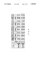
- FIG. 1 (Prior Art) is a table demonstrating the increase in junction resistance with exposure to 90% relative humidity conditions of a prior art formulation
- FIG. 2 is a photomicrograph of silver agglomerates utilized in the formulation of Example II at 5000X magnification and illustrating the many rough surface characteristics;
- FIG. 3A is a table demonstrating the stability of the junction resistance upon exposure to 90% relative humidity conditions of a formulation prepared in accordance with Example II of the present invention in which the electrical leads were cleaned with acetone prior to effecting the connection;
- FIG. 3B is another table demonstrating the stability of junction resistance upon exposure to 90% relative humidity conditions of the formulation of Example II of the present invention in which the electrical leads were cleaned with an inorganic acid prior to effecting the connection;
- FIG. 4 is another table demonstrating the stability of junction resistance upon exposure to 90% relative humidity conditions of the formulation of Example III;
- FIG. 5 is another table demonstrating the stability of junction resistance upon exposure to 90% relative humidity conditions of the formulation of Example IV;
- FIG. 6 is another table demonstrating the improved junction resistance upon exposure to 90% relative humidity conditions of the formulation of Example V;
- FIG. 7 is another table demonstrating the stability of junction resistance upon exposure to 90% relative humidity conditions of the formulation of Example VI;
- FIG. 8 is another table demonstrating the stability of junction resistance upon exposure to 90% relative humidity conditions of the formulation of Example VII;
- FIG. 9 is another table demonstrating the stability of junction resistance upon exposure to 90% relative humidity conditions of the formulation of Example VIII;
- FIG. 10 is another table demonstrating the stability of junction resistance upon exposure to 90% relative humidity conditions of the formulation of Example IX.
- FIG. 11 is another table demonstrating the stability of junction resistance upon exposure to 90% relative humidity conditions of the formulation of Example X.
- a conductive cement having improved performance characteristics under adverse operating conditions, particularly high humidity and temperature conditions. Since all polymeric carriers are moisture permeable to some extent the conductive particle filler must be such that formation of non-conductive oxidation products is minimal with continued exposure to humidity. Additionally, the carrier should have characteristics that enhance electrical conduction at the interfacial boundary between the cement and the surface of the electrical lead as well as conduction between the conductive particles of the filler; to this end, a silver particle or a silver-plated particle filler is preferred, although other noble metals and nickel are suitable as well.
- the various formulations in accordance with the present invention presented below utilize fillers which are silver agglomerates, particles, flakes, and powders as well as silver-plated particles.
- the agglomerates are characterized by an irregular body-shape and a surface with many recesses that define projecting salients or ridges at the boundaries between the recesses.
- These agglomerates are preferably characterized as having a length, width, and thickness aspect ratio of approximately 1:1:1 and, as a consequence, are believed to function as force vectors which can form a gas-tight seal and pierce oxides present at a connection interface to maintain stable electrical contact even when subjected to elevated temperatures and humidities.
- the plated particles employed are in the form of non-conductive inorganic spheroids plated with silver as well as silver coated non-noble metals such as nickel.
- the agglomerates and the plated particles are believed to form the primary electron conduction path in the cured carrier by direct surface-to-surface inter-particle contact and to participate in contacting and penetrating the surface of the electrical lead surface to be connected, in response to the compaction that results from the volumetric shrinkage of the polymeric carrier.
- the smaller powder particles as in the case of the larger agglomerates or particles, can function singly or in groups, to penetrate any oxides or surface contaminants present at the interfacial surface between the cement and the component lead at the junction in response to the internal forces caused by volumetric shrinkage of the carrier.
- agglomerates and powder particles having the described morphology in effective amounts and combined with the described carrier provide moisture resistant electrical contact
- flake-like or platelet-like conductive particles have also been found useful.
- Flake-like particles are defined as particulates having a thickness dimension which is substantially (i.e., an order or magnitude) smaller than its length and width. In effective amounts, the flake-like particles tend to preferentially overlap or overlay one another in an aligned relationship enhancing the conductivity of the system.
- the carrier possesses a volumetric shrinkage characteristic greater than about 6.8% in order to assure internal compaction of the conductive particle filler. Additional characteristics of the carrier can include good adhesion, wettability, and good handling. Since many conductive cements are applied by screen-printing, stencil or similar techniques, the uncured polymeric carrier should have a viscosity which provides a final conductive cement suitable for application by such processes. Carrier rheological properties should be effective for stenciling, screen printing, or pneumatic deposition processes commonly used for applying conductive cement. Suitable viscosities may range from 50,000 to 25,000 cps.
- Linear shrinkage values were determined by applying a line of the uncured adhesive to a flat surface, curing the adhesive, and determining shrinkage as a function of the uncured and cured line lengths. Volumetric shrinkage characteristics between the uncured and the cured cement were determined by the following protocol:
- the density ⁇ u of the uncured (carrier) epoxy solution was determined at room temperature by determining the weight W of an epoxy-filled container of known volume V and known empty weight w as follows:
- the density ⁇ c of the cured epoxy was determined in accordance with the Archimedean principle (ASTM C693) at room temperature using METTLER density determination kit E-210250 and an OHAUS precision balance 160D.
- the dry weight A of the cured epoxy specimen in air is determined and its weight P in a liquid of known density ⁇ l is determined and the density ⁇ c of the cured epoxy is determined as follows:
- the volumetric shrinkage Vs of the uncured and cured epoxies is determined by determining the volumes of the uncured and cured epoxy using the density values ⁇ u and ⁇ c obtained above.
- the volume of the uncured epoxy V u is determined by measuring the weight W of a specimen of the uncured epoxy and determining its volume as follows:
- the epoxy is then cured in accordance with the cure schedule presented below and the weight W c of the now-cured specimen is determined.
- the volume of the cured epoxy V c is determined as follows:
- volumetric shrinkage Vs in per cent is then determined as follows:
- a conductive cement manufactured by Emerson & Cuming of Lexington, Mass. and sold under the AMICONTM CSM-933-65-1 designation was used to connect a 68-pin surface-mount device (SMD), two 44-pin surface-mount devices, and a ten resistor series string in a test circuit and subjected to a 140° C. cure for a period of 10 minutes consistent with the manufacturer's instructions.
- the pins of the various surface-mount devices were series-connected through resistive elements within the surface-mount devices and the total junction resistance determined by subtracting the cumulative series resistance of the intra-device components from the total measured resistance.
- the resistance measurement for the resistor-string was effected by subtracting the cumulative values of the resistors that comprised the string from the total series resistance to arrive at a cumulative junction resistance value.
- the resistance of the intra-device elements of the surface-mount devices as well as the resistors within the resistor string was stable within the temperature and humidity range of the tests as verified by control circuits.
- the initial junction resistance in ohms was measured at room temperature and at test conditions of 60° C. and 90% relative humidity as shown in FIG. 1. The resistance was then again measured after 15.5, 24, 39 and 63 hours exposure at the 60° C. and 90% relative humidity test conditions. As shown in FIG. 1, the ohmic resistance of all junctions increased with time at 90% relative humidity with an extrapolated value for 1000-hours indicating a substantial increase for the 68-pin devices and the two 44-pin devices and less of an increase for the resistor-string.
- a conductive cement is prepared using a conductive filler including three types of silver particulate A, B, and C.
- Particulate A is a silver flake having a Fisher Sub-Sieve Size (FSSS) in the range of 0.90-1.30 micrometer, a tap density (by Tap-Pak Volumeter) of 3.0 to 3.5 g/cc, a Scott apparent density of 30-35 g/in 3 , a surface area of 0.3-0.6 m 2 /g and a size distribution of 90% ⁇ 14.00 micrometer, 50% ⁇ 7.00 micrometer, and 10% ⁇ 2.00 micrometer.
- the size distribution data presented herein were determined with a Leeds and Northrop Microtrac.
- a suitable particulate A is "Silver Flake #53" available from the Electronic Materials Division of the Metz Metallurgical Corporation, South Plainfield, N.J.
- Particulate B is silver agglomerate having a Fisher sub-sieve size (FSSS) of 0.6 micrometers, a tap density (by Tap-Pak Volumeter) of 1.85 g/cc, a Scott apparent density of 16.7 g/in 3 , a surface area of 1.62m 2 /g and a size distribution of 100% ⁇ 10.6 micrometers, 90% ⁇ 8.10 micrometers, 50% ⁇ 4.4 micrometers, and 10% ⁇ 1.40 micrometers with a mean size of 4.5 micrometers.
- a suitable particulate B is "Silver Powder SPS-100" available from Metz Metallurgical Corporation. This silver agglomerate as shown in the photomicrograph of FIG. 2, has many rough surface features.
- Particulate C is silver powder having a Fisher Sub-Sieve Size (FSSS) of 0.70 microns, a tap density (by Tap-Pak Volumeter) of 2.75 g/cc, a Scott apparent density of 17.5 g/in 3 , and a surface area of 1.84 m 2 /g and a size distribution of 100% ⁇ 5.27 micrometer, 90% ⁇ 3.16 micrometer, 50% ⁇ 1.25 micrometer, and 10% ⁇ 0.51 micrometer.
- FSSS Fisher Sub-Sieve Size
- a suitable particulate C is "Fine Silver Powder S-ED" available from Metz Metallurgical Corporation.
- Particulates A, B, and C are mixed in a weight ratio of about 40%, 30%, and 30% to constitute the metallic silver filler that is admixed with the carrier.
- the carrier comprises a polymer mixture of two epoxy resins, Epoxy A and Epoxy B.
- Epoxy A is a bisphenol F epoxy resin such as "Aratronic 5046", a bisphenol F diglycidyl ether, having a relatively low viscosity of 1400 cps at 25° C., available from the Ciba-Geigy Corporation.
- Epoxy B is a liquid phenol epoxy novolac resin, such as "Quatrex 2010", a phenol epoxy novolac resin having a relatively high viscosity of 25,000-45,000 cps at 25° C., available from Dow Chemical Corporation, Midland, Mich.
- the polymeric carrier may also include a conventional hardener such as an imidazole, for instance, N-(2-cyanoethyl)-2-ethyl,4-methylimidazole, available from PolyOrganix Corporation of Newburyport, Mass. under the CURIMIDTM-CN designation.
- a conventional hardener such as an imidazole, for instance, N-(2-cyanoethyl)-2-ethyl,4-methylimidazole, available from PolyOrganix Corporation of Newburyport, Mass. under the CURIMIDTM-CN designation.
- the polymeric carrier can also include a coupling or wetting agent to provide enhanced wetting of the uncured material.
- a representative coupling agent is gamma-glycidoxypropyltrimethoxysilane, available from the Union Carbide Company under the "A-187" designation.
- Yet another adjuvant includable in the polymeric carrier of the present invention is gamma-butyrolactone, available from the Aldrich Chemical Co., Milwaukee, Wis., which material functions as a diluent to adjust viscosity.
- a conductive cement composition having the following formulation was prepared:
- the 76.5% silver content represents a preferred value for common application techniques such as application by stencil, screen print, tampo print, syringe, etc.
- this conductive cement composition can exhibit electrical instability with resistance increasing by an order of magnitude under various test conditions. Above 78% this conductive cement composition is too viscous for use in stencil and screen printing applications, although still suitable for application by syringe.
- the above polymeric carrier was determined to have a volumetric shrinkage 17%.
- electrical leads were initially cleaned with acetone and the above formulation used to connect a 68-pin surface-mount device (SMD), a 44-pin surface-mount device, and a series-connected resistor string in each of six test circuits (Trials 1-6) as described in Example I.
- the junction resistance was measured at room temperature and at test conditions of 60° C. and 90% relative humidity as shown in FIG. 3A.
- the resistivity was then again measured after 17, 40, 112, 306, 618, and 1002 hours exposure at the 60° C. and 90% relative humidity test conditions.
- the ohmic resistance of all junctions varied minimally after 1002 hours at 90% relative humidity with only one set of junctions having an increase in resistance over 11%.
- the electrical leads of the above-described devices were first cleaned with an inorganic acid and the connections made with the formulation of this Example in the manner described above.
- the junction resistance was measured at room temperature and at test conditions of 60° C. and 90% relative humidity as shown in FIG. 3B.
- the resistivity was then measured after 14.5, 117.5, 149, 297, and 969 hours exposure at the 60° C. and 90% relative humidity test conditions.
- the ohmic resistance of all junctions varied minimally after 969 hours at 90% relative humidity with only one set of junctions having an increase in resistance over 12%.
- a conductive cement is prepared using a conductive particle filler of three types of silver particulates A,B, and C.
- Particulates A, B, and C are those described above in Example II and are similarly mixed in a weight ratio of 40%, 30%, and 30% to constitute a filler that is admixed with a carrier.
- the carrier comprises a single epoxy resin.
- the epoxy is a liquid bisphenol A epoxy resin such as "Quantrex 1010", viscosity of 11,000-14,000 cps at 25° C., available from the Dow Chemical Corporation.
- the polymeric carrier can also include a hardener (N-(2-cyanoethyl)-2-ethyl,4-methylimidazole), gamma-glycidoxypropyltrimethoxysilane and a diluent gamma-butyrolactone.
- a hardener N-(2-cyanoethyl)-2-ethyl,4-methylimidazole
- gamma-glycidoxypropyltrimethoxysilane and a diluent gamma-butyrolactone.
- a conductive cement was prepared with the following formulation:
- the above polymeric carrier was determined to have a volumetric shrinkage of 13% and was used to connect a 68-pin surface-mount device (SMD), a 44-pin surface-mount device, and a series-connected resistor string in each of two test circuits (Trials 1-2) as described in Example I.
- the junction resistance was measured at room temperature and at test conditions of 60° C. and 90% relative humidity as shown in FIG. 4.
- the resistivity was then again measured after 15, 65, and 141 hours exposure at the 60° C. and 90% relative humidity test conditions.
- the ohmic resistance of all junctions varied minimally after 141 hours at 90% relative humidity with two (2) sets of junctions having an increase in resistance over 2%.
- a conductive cement is prepared using a conductive particle filler of two types of silver particulates A and C which are identical to particulates A and C described above for Example II.
- Particulates A and C are desirably mixed in a weight ratio of 40% and 60% to constitute the filler that is admixed with the carrier.
- the carrier comprises a mixture of two epoxy resins, Epoxy A and Epoxy B.
- Epoxy A is a bisphenol F epoxy resin such as "Aratronic 5046”.
- Epoxy B is a liquid phenol epoxy novolac resin, such as "Quatrex 2010”.
- the polymeric carrier can also include a hardener (N-(2-cyanoethyl)-2-ethyl,4-methylimidazole) a coupling agent (gamma-glycidoxypropyltrimethoxysilane) and a diluent (gamma-butyrolactone).
- a hardener N-(2-cyanoethyl)-2-ethyl,4-methylimidazole
- a coupling agent gamma-glycidoxypropyltrimethoxysilane
- a diluent gamma-butyrolactone
- a conductive cement was prepared with the following formulation:
- the above polymeric carrier was determined to have a volumetric shrinkage of 10% and was used to connect a 68-pin surface-mount device (SMD), a 44-pin surface-mount device, and a series-connected resistor string in each of six test circuits (Trials 1-6) as described in Example I.
- the junction resistance was measured at room temperature and at test conditions of 60° C. and 90% relative humidity as shown in FIG. 5.
- the resistivity was then again measured after 62, 136, 1073, and 1598 hours exposure at the 60° C. and 90% relative humidity test conditions.
- the ohmic resistance of all junctions varied minimally after 1598 hours at 90% relative humidity with only one set of junctions having an increase in resistance over 19%.
- a conductive cement is prepared using a conductive filler of three types of silver particulates A, B, and C which are identical to particulates A, B, and C described above for Example II.
- Particulates A, B, and C are desirably mixed in a weight ratio of 40%, 30%, and 30% to constitute the filler that is mixed with a carrier.
- the carrier comprises a single epoxy/solvent combination.
- the epoxy is a bisphenol A epoxy resin such as ⁇ EPONOL (R) 53-BH-35 ⁇ , a high molecular weight epoxyavailable from the Shell Chemical Company, Houston, Tex.
- the epoxy resin represents about 35% of the as-supplied material with the remainder comprising a solvent of about 75% methyl ethyl ketone (MEK) and 25% propylene glycol methylether (PGME).
- MEK methyl ethyl ketone
- PGME propylene glycol methylether
- a conductive cement composition in accordance with the present invention was prepared and has the following formulation:
- the above polymeric carrier was determined to have a volumetric shrinkage of 65% and was used to connect a 68-pin surface-mount device (SMD), a 44-pin surface-mount device, and a series-connected resistor string in each of six test circuits (Trials 1-6) as descried in Example I.
- the junction resistance was measured at room temperature and at test conditions of 60° C. and 90% relative humidity as shown in FIG. 6.
- the resistivity was then measured after 6, 13, 349, and 1530 hours exposure at the 60° C. and 90% relative humidity test conditions.
- the ohmic resistance of all junctions varied minimally after 1530 hours at 90% relative humidity with only one set of junctions having an increase in resistance over 10%.
- a conductive cement is prepared using a conductive particle filler of three types of silver particulates A, B, and C which are identical to particulates A, B, and C described above for Example II.
- Particulates A, B, and C are desirably mixed in a weight ratio of 40%, 30%, and 30% to constitute a filler that is mixed with a carrier.
- the carrier comprises a single epoxy/solvent combination.
- the epoxy is a novolac epoxy resin such as "Quatrex 2010", a phenol epoxy novolac resin having a relatively high viscosity of 25,000-45,000 cps at 25° C. available from Dow Chemical Corporation.
- the solvent 2-(2-ethoxyethoxy) ethyl acetate is available under the tradename "Carbitol” acetate from the Eastman Kodak Co., Rochester, N.Y. and is also known as diethylene glycol monoethyl ether acetate.
- the polymeric carrier can also include a hardener (N-(2-cyanoethyl)-2-ethyl,4-methylimidazole) and a coupling agent (gamma-glycidoxypropyltrimethoxysilane).
- a hardener N-(2-cyanoethyl)-2-ethyl,4-methylimidazole
- a coupling agent gamma-glycidoxypropyltrimethoxysilane
- a conductive cement was prepared with the following formulation:
- the above polymeric carrier was determined to have a volumetric shrinkage of 25% and was used to connect a 68-pin surface-mount device (SMD), a 44-pin surface-mount device, and a series-connected resistor string in each of six test circuits (Trials 1-6) as described in Example I.
- the junction resistance was measured at room temperature and at test conditions of 60° C. and 90% relative humidity as shown in FIG. 7.
- the resistivity was then again measured after 14, 62, and 1025 hours exposure at 60° C. and 90% relative humidity test conditions. As shown by the % increment columns in FIG. 7, the ohmic resistance of all junctions varied minimally after 1025 hours at 90% relative humidity.
- a conductive cement is prepared using a conductive particle filler of three types of silver particulates A, B, and C which are identical to particulates A, B, and C described above for Example II.
- Particulates A, B, and C are desirably mixed in a weight ratio of 40%, 30%, and 30% to constitute the metallic silver filler that is admixed with a carrier.
- the carrier comprises a mixture of two epoxy resins, Epoxy A and Epoxy B.
- Epoxy A is a bisphenol A epoxy resin such as "Eponol 53" described above and Epoxy B is a liquid phenol Epoxy novolac resin, such as "Quatrex 1010", also described above.
- the polymeric carrier can also include hardeners I and II.
- Hardener I is a polyoxypropylenediamine available under the Jeffamine D-230 designation from the Texaco Chemical Company
- hardener II is a triethyleneglycoldiamine available under the Jeffamine EDR 148 designation, also from the Texaco Chemical Company.
- the polymeric carrier may include an accelerator to promote curing.
- a suitable accelerator such as a mixture of aliphatic amines is available from the Texaco Chemical Company under the ⁇ 399 ⁇ designation.
- the polymeric carrier may also include an adhesion promoter such as a glyceryl poly(oxypropylene) triamine available under the Jeffamine T-5000 designation from the Texaco Chemical Company.
- a conductive cement composition was prepared with the following formulation:
- the above polymeric carrier was determined to have a volumetric shrinkage of 19% and was used to connect a 68-pin surface-mount device (SMD), a 44-pin surface-mount device, and a series-connected resistor string in each of six test circuits (Trials 1-6) as described in Example I.
- the junction resistance was measured at room temperature and at test conditions of 60° C. and 90% relative humidity as shown in FIG. 8.
- the resistivity was then again measured after 15, 191, and 981 hours exposure at the 60° C. and 90% relative humidity test conditions.
- the ohmic resistance of all junctions varied minimally after 1598 hours at 90% relative humidity with only one set of junctions having an increase in resistance over 8%.
- a conductive cement is prepared using a conductive particle filler of two types of conductive particles, particulates A and D.
- Particulate A is identical to particulate A described above for Example I.
- Particulate D comprises silver-coated nickel particles having a mean particle dimension of 28u with an actual size distribution of 90% ⁇ 48.19u, 50% ⁇ 27.97u, and 10% ⁇ 12.36u.
- a suitable particulate D is available from Novamet Specialty Products Corp., an INCO Company, 681 Lawlins Road, Wyckof, N.J. 07481 (201-891-7976).
- Particulates A and D are desirably mixed in a weight ratio of 80% and 20% to constitute a filler that is admixed with a carrier.
- the carrier comprises a mixture of two epoxy resins, Epoxy A and Epoxy B.
- Epoxy A is a bisphenol F epoxy resin such as "Aratronic 5046"
- Epoxy B is a liquid phenol epoxy novolac resin, such as "Quatrex 2010”.
- the polymeric carrier can also include a hardener (N-(2-cyanoethyl)-2-ethyl,4-methylimidazole) and a coupling agent (gamma-glycidoxypropyltrimethoxysilane).
- a hardener N-(2-cyanoethyl)-2-ethyl,4-methylimidazole
- a coupling agent gamma-glycidoxypropyltrimethoxysilane
- a conductive cement composition was prepared with the following formulation:
- the above polymeric carrier formulation was determined to have a volumetric shrinkage of 7.6% and was used to connect a 68-pin surface-mount device (SMD), a 44-pin surface-mount device, and a series-connected resistor string in each of six test circuits (Trials 1-6) as described in Example I.
- the junction resistance was measured at room temperature and at test conditions of 60° C. and 90% relative humidity as shown in FIG. 9.
- the resistivity was then again measured after 119, 503, and 1146 hours exposure at the 60° C. and 90% relative humidity test conditions.
- the ohmic resistance of all junctions varied minimally after 1146 hours at 90% relative humidity with only one set of junctions having an increase in resistance over 15%.
- a conductive cement is prepared using a conductive particle filler of two types of conductive particles, particulates A and E, of which particulate A is identical to particulate A described above for Example I.
- Particulates E are silver-coated nickel particles of about 32 % wt. silver having a Scott apparent density of 3.66 g/in 3 , a surface area of 0.22 m 2 /g, a powder resistivity of 0.4 m ohm.cm, and a mean particle dimension of 21u with an actual size distribution of 90% ⁇ 29.3 micrometer, 50% ⁇ 19.5 micrometer, and 10% ⁇ 13.9 micrometer.
- a suitable particulate E is available from Potter Industries, Inc., Carlstadt, N.J. under the Conducto-O-Fil Silver Nickel designation.
- Particulates A and E are desirably mixed in a weight ratio of 80% and 20% to constitute a filler that is admixed with a carrier.
- the carrier comprises principally a mixture of two epoxy resins, Epoxy A and Epoxy B.
- Epoxy A is a bisphenol F epoxy resin such as "Aratronic 5046"
- Epoxy B is a liquid phenol epoxy novolac resin, such as "Quatrex 2010”.
- the polymeric carrier can also include a hardener (N-(2-cyanoethyl)-2-ethyl,4-methylimidazole) and a coupling agent (gamma-glycidoxypropyltrimethoxysilane).
- a hardener N-(2-cyanoethyl)-2-ethyl,4-methylimidazole
- a coupling agent gamma-glycidoxypropyltrimethoxysilane
- a conductive cement was prepared with the following formulation:
- the above polymeric carrier was determined to have a volumetric shrinkage characteristic of 7.6% and was used to connect a 68-pin surface-mount device (SMD), a 44-pin surface-mount device, and a series-connected resistor string in each of six test circuits (Trials 1-6) as described in Example I.
- the junction resistance was measured at room temperature and at test conditions of 60° C. and 90% relative humidity as shown in FIG. 10.
- the resistivity was then again measured after 65, 453, 1096 hours exposure at the 60° C. and 90% relative humidity test conditions.
- the ohmic resistance of all junctions varied minimally after 1096 hours at 90% relative humidity with only one set of junctions having an increase in resistance over 14%.
- a conductive cement is prepared using a conductive particle filler of two types of conductive particles, particulates A and F, of which particulate A is identical to particulate A described above for Example I.
- Particulates F are silver-coated glass spheres of about 23.8% silver having a Scott apparent density of 0.81 g/in 3 , a powder resistivity of 2.63 milli-ohm cm, and a mean particle dimension of 13 micrometers with an actual size distribution of 90% ⁇ 20.0 micrometer, 50% ⁇ 12.1 micrometer, and 10% ⁇ 7.1 micrometer.
- a suitable particulate F is available from Potter Industries, Inc., Carlstadt, N.J. 07072 under the Conducto-O-Fil. Silvered Glass Spheres designation.
- Particulates A and F are desirably mixed in a weight ratio of 92% and 8% to constitute a filler that is admixed with a carrier.
- the carrier comprises principally a mixture of two epoxy resins, Epoxy A and Epoxy B.
- Epoxy A is a bisphenol F epoxy resin such as "Aratronic 5046"
- Epoxy B is a liquid phenol epoxy novolac resin, such as "Quatrex 2010”.
- the polymeric carrier can also include a conventional hardener (N-(2-cyanoethyl)-2-ethyl,4-methylimidazole) and a coupling agent (gamma-glycidoxypropyltrimethoxysilane).
- a conventional hardener N-(2-cyanoethyl)-2-ethyl,4-methylimidazole
- a coupling agent gamma-glycidoxypropyltrimethoxysilane
- a conductive cement was prepared with the following formulation:
- the above polymeric carrier was determined to have a volumetric shrinkage characteristic of 7.6% and was used to connect a 68-pin surface-mount device (SMD), a 44-pin surface-mount device, and a series-connected resistor string in each of six test circuits (Trials 1-6) as described in Example I.
- the junction resistance was measured at room temperature and at test conditions of 60° C. and 90% relative humidity as shown in FIG. 11.
- the resistivity was then again measured after 65, 453, and 1096 hours exposure at the 60° C. and 90% relative humidity test conditions.
- the ohmic resistance of all junctions varied minimally after 1096 hours at 90% relative humidity with only two (2) sets of junctions having an increase in resistance over 15%.
- the present invention advantageously provides an electrically conductive cement composition having substantially stable conductivity and resistance characteristics under high humidity conditions and is believed to achieve this result as a consequence of providing a cement having a volumetric shrinkage rate in a range that assures particle-to-particle contact and particle-to-connection surface contact to produce a reliable connection.
Abstract
Description
ρ.sub.u =(W-w)/V Eq. 1
ρ.sub.c =(A/P)ρ.sub.l Eq. 2
V.sub.u =W.sub.u ρ.sub.u Eq. 3
V.sub.c =W.sub.c ρ.sub.c Eq. 4
V.sub.s =[(V.sub.u -V.sub.c)/V.sub.u ](100) Eq. 5
______________________________________
              Batch Quantity - % weight
Component     (normalized weight units)
______________________________________
Epoxy A       8.275
Epoxy B       8.275
Hardener      3.973
Diluent       1.985
Coupling Agt   0.993
total epoxy wt =
              23.5%
Particle A    30.600
Particle B    22.950
Particle C    22.950
total silver wt =
              76.5%
______________________________________
______________________________________
              Batch Quantity - % weight
Component     (normalized weight units)
______________________________________
Epoxy         16.55
Hardener      3.97
Coupling Agent
              0.99
Diluent       1.99
total epoxy wt =
              23.50%
Particle A    30.600
Particle B    22.950
Particle C    22.950
total silver wt =
              76.5%
______________________________________
______________________________________
              Batch Quantity - % weight
Component     (normalized weight units)
______________________________________
Epoxy A       8.21
Epoxy B       8.21
Hardener      3.94
Diluent       0.66
Coupling Agent
              0.99
total epoxy wt =
              22.0%
Particle A    31.20
Particle C    46.80
total silver wt =
              78.0%
______________________________________
______________________________________
              Batch Quantity - % weight
Component     (normalized weight units)
______________________________________
Epoxy         12.921
Solvent       23.996
total epoxy wt =
              36.917%
Particle A    25.233
Particle B    18.925
Particle C    18.925
total silver wt =
              63.083%
______________________________________
______________________________________
              Batch Quantity - % weight
Component     (normalized weight units)
______________________________________
Epoxy         14.79
Solvent       6.34
Hardener      1.18
Coupling Agent
              0.89
total epoxy wt =
              23.20%
Particle A    30.72
Particle B    23.04
Particle C    23.04
total silver wt =
              76.80%
______________________________________
______________________________________
               Batch Quantity - % weight
Component      (normalized weight units)
______________________________________
Epoxy A        13.50
Epoxy B        8.94
Hardener I     2.59
Hardener II    0.36
Accelerator    0.27
Adhesion Promoter
               1.34
total epoxy wt =
               27.00%
Particle A     29.20
Particle B     21.90
Particle C     21.90
total silver wt =
               73.00%
______________________________________
______________________________________
              Batch Quantity - % weight
Component     (normalized weight units)
______________________________________
Epoxy A       7.50
Epoxy B       7.50
Hardener      3.60
Coupling Agent
              0.90
total epoxy wt =
              19.5%
Particle A    64.40
Particle D    16.10
total silver wt =
              80.5%
______________________________________
______________________________________
              Batch Quantity - % weight
Component     (normalized weight units)
______________________________________
Epoxy A       7.50
Epoxy B       7.50
Hardener      3.60
Coupling Agent
              0.90
total epoxy wt =
              19.5%
Particle A    64.40
Particle E    16.10
total silver wt =
              80.5%
______________________________________
______________________________________
              Batch Quantity - % weight
Component     (normalized weight units)
______________________________________
Epoxy A       7.88
Epoxy B       7.88
Hardener      3.78
Coupling Agent
              .96
total epoxy wt =
              20.5%
Particle A    73.14
Particle F    6.36
total silver wt =
              79.5%
______________________________________
Claims (21)
Priority Applications (13)
| Application Number | Priority Date | Filing Date | Title |
|---|---|---|---|
| US07/533,682 US5183593A (en) | 1989-11-14 | 1990-06-04 | Electrically conductive cement |
| GB9024669A GB2239244B (en) | 1989-11-14 | 1990-11-13 | Moisture resistant electrically conductive cements and methods for making and using same |
| EP90121829A EP0428165B1 (en) | 1989-11-14 | 1990-11-14 | Moisture resistant electrically conductive cements and method for making and using same |
| AT02012317T ATE355594T1 (en) | 1989-11-14 | 1990-11-14 | MOISTURE RESISTANT ELECTRICALLY CONDUCTIVE CEMENTS AND METHOD FOR THE PRODUCTION AND USE OF THE SAME |
| AU70480/91A AU7048091A (en) | 1989-11-14 | 1990-11-14 | Moisture resistant electrically conductive cements and methods for making and using same |
| CA002068657A CA2068657C (en) | 1989-11-14 | 1990-11-14 | Moisture resistant electrically conductive cements and methods for making and using same |
| PCT/US1990/006659 WO1991007759A1 (en) | 1989-11-14 | 1990-11-14 | Moisture resistant electrically conductive cements and methods for making and using same |
| JP2310155A JPH03269909A (en) | 1989-11-14 | 1990-11-14 | Damp-proof conductive cement and manufacture and use thereof |
| DE4036274A DE4036274A1 (en) | 1989-11-14 | 1990-11-14 | MOISTURE-RESISTANT ELECTRICALLY CONDUCTIVE ADHESIVES, METHOD OF MANUFACTURING AND THEIR USE |
| EP02012317A EP1246206B1 (en) | 1989-11-14 | 1990-11-14 | Moisture resistant electrically conductive cements and method for the production and using same |
| DE69034236T DE69034236T2 (en) | 1989-11-14 | 1990-11-14 | Moisture-resistant electrically conductive cements and method of making and using same |
| DE69034020T DE69034020T2 (en) | 1989-11-14 | 1990-11-14 | Moisture-resistant electrically conductive cements and method of making and using the same |
| AT90121829T ATE228264T1 (en) | 1989-11-14 | 1990-11-14 | MOISTURE RESISTANT ELECTRICALLY CONDUCTIVE CEMENTS AND METHOD FOR THE PRODUCTION AND USE OF THE SAME |
Applications Claiming Priority (2)
| Application Number | Priority Date | Filing Date | Title |
|---|---|---|---|
| US07/436,199 US5180523A (en) | 1989-11-14 | 1989-11-14 | Electrically conductive cement containing agglomerate, flake and powder metal fillers |
| US07/533,682 US5183593A (en) | 1989-11-14 | 1990-06-04 | Electrically conductive cement |
Related Parent Applications (1)
| Application Number | Title | Priority Date | Filing Date |
|---|---|---|---|
| US07/436,199 Continuation-In-Part US5180523A (en) | 1989-11-14 | 1989-11-14 | Electrically conductive cement containing agglomerate, flake and powder metal fillers |
Publications (1)
| Publication Number | Publication Date |
|---|---|
| US5183593A true US5183593A (en) | 1993-02-02 |
Family
ID=27030848
Family Applications (1)
| Application Number | Title | Priority Date | Filing Date |
|---|---|---|---|
| US07/533,682 Expired - Lifetime US5183593A (en) | 1989-11-14 | 1990-06-04 | Electrically conductive cement |
Country Status (2)
| Country | Link |
|---|---|
| US (1) | US5183593A (en) |
| JP (1) | JPH03269909A (en) |
Cited By (31)
| Publication number | Priority date | Publication date | Assignee | Title |
|---|---|---|---|---|
| US5514729A (en) * | 1993-11-17 | 1996-05-07 | Sophia Systems Co., Ltd. | Ultraviolet hardenable, solventless electrically conductive polymeric material |
| US5531020A (en) * | 1989-11-14 | 1996-07-02 | Poly Flex Circuits, Inc. | Method of making subsurface electronic circuits |
| WO1997015933A1 (en) * | 1995-10-23 | 1997-05-01 | Hoechst Celanese Corporation | Improved electrically and thermally conducting compositions for actuators |
| US5891367A (en) * | 1998-02-23 | 1999-04-06 | General Motors Corporation | Conductive epoxy adhesive |
| WO2000042097A1 (en) * | 1999-01-11 | 2000-07-20 | Dymax Corporation | Electrically conductive resinous material and radiation curable formulation for producing the same |
| WO2001007488A1 (en) * | 1999-07-26 | 2001-02-01 | Dymax Corporation | Radiation curable formulation for producing electrically conductive resinous material, method of use, and article produced |
| US20030038280A1 (en) * | 2001-08-24 | 2003-02-27 | Hiroki Kojo | Thermosetting electroconductive paste for electroconductive bump use |
| US20040169162A1 (en) * | 2003-02-28 | 2004-09-02 | Yue Xiao | Conductive materials with electrical stability and good impact resistance for use in electronics devices |
| US20060065435A1 (en) * | 2000-04-14 | 2006-03-30 | Saint-Gobain Glass France | Transparent substrate provided with electroconductive strips |
| US20060207713A1 (en) * | 2002-12-17 | 2006-09-21 | Jaehwan Eun | Method for preparating film structure comprising ferroelectric single crystal layer |
| US20090139753A1 (en) * | 2006-02-06 | 2009-06-04 | Lg Chem, Ltd. | Copper Clad Laminate for Chip on Film |
| US20090155597A1 (en) * | 2007-12-18 | 2009-06-18 | 3M Innovative Properties Company | Conductive adhesive precursor, method of using the same, and article |
| US7772773B1 (en) | 2003-11-13 | 2010-08-10 | Imaging Systems Technology | Electrode configurations for plasma-dome PDP |
| US7863815B1 (en) | 2006-01-26 | 2011-01-04 | Imaging Systems Technology | Electrode configurations for plasma-disc PDP |
| US20110038124A1 (en) * | 2008-04-21 | 2011-02-17 | Honeywell International Inc. | Thermal interconnect and interface materials, methods of production and uses thereof |
| US8035303B1 (en) | 2006-02-16 | 2011-10-11 | Imaging Systems Technology | Electrode configurations for gas discharge device |
| US8113898B1 (en) | 2004-06-21 | 2012-02-14 | Imaging Systems Technology, Inc. | Gas discharge device with electrical conductive bonding material |
| US8198811B1 (en) | 2002-05-21 | 2012-06-12 | Imaging Systems Technology | Plasma-Disc PDP |
| US20120172714A1 (en) * | 2010-12-29 | 2012-07-05 | Assaf Govari | Braid with integrated signal conductors |
| US8278824B1 (en) | 2006-02-16 | 2012-10-02 | Imaging Systems Technology, Inc. | Gas discharge electrode configurations |
| US8299696B1 (en) | 2005-02-22 | 2012-10-30 | Imaging Systems Technology | Plasma-shell gas discharge device |
| US8339041B1 (en) | 2004-04-26 | 2012-12-25 | Imaging Systems Technology, Inc. | Plasma-shell gas discharge device with combined organic and inorganic luminescent substances |
| US8368303B1 (en) | 2004-06-21 | 2013-02-05 | Imaging Systems Technology, Inc. | Gas discharge device with electrical conductive bonding material |
| US8410695B1 (en) | 2006-02-16 | 2013-04-02 | Imaging Systems Technology | Gas discharge device incorporating gas-filled plasma-shell and method of manufacturing thereof |
| JP2013196954A (en) * | 2012-03-21 | 2013-09-30 | Kyoto Elex Kk | Thermosetting conductive paste composition |
| US8618733B1 (en) | 2006-01-26 | 2013-12-31 | Imaging Systems Technology, Inc. | Electrode configurations for plasma-shell gas discharge device |
| US20140008112A1 (en) * | 2010-10-05 | 2014-01-09 | Hong Jiang | Single Component, Low Temperature Curable Polymeric Composition And Related Method |
| US9013102B1 (en) | 2009-05-23 | 2015-04-21 | Imaging Systems Technology, Inc. | Radiation detector with tiled substrates |
| US9024526B1 (en) | 2012-06-11 | 2015-05-05 | Imaging Systems Technology, Inc. | Detector element with antenna |
| US20170104283A1 (en) * | 2014-06-12 | 2017-04-13 | Pfisterer Kontaktsysteme Gmbh | Apparatus for making contact with an electrical conductor, and connection or connecting device with an apparatus of this kind |
| US20210087441A1 (en) * | 2019-09-20 | 2021-03-25 | Blue Ocean & Black Stone Technology Co., Ltd. (Beijing) | Recyclable Conductive Adhesive Composition for Led Packaging and Preparation Method Thereof, Recycling Method and Recycled Conductive Silver Powder |
Families Citing this family (2)
| Publication number | Priority date | Publication date | Assignee | Title |
|---|---|---|---|---|
| JPH06136332A (en) * | 1992-10-21 | 1994-05-17 | Pioneer Electron Corp | Anisotropically conductive adhesive |
| CN108779373A (en) * | 2015-10-15 | 2018-11-09 | 汉高知识产权控股有限责任公司 | Nickel and contain purposes of the alloy of nickel as conductive filler in adhesive formulation |
Citations (13)
| Publication number | Priority date | Publication date | Assignee | Title |
|---|---|---|---|---|
| US4113981A (en) * | 1974-08-14 | 1978-09-12 | Kabushiki Kaisha Seikosha | Electrically conductive adhesive connecting arrays of conductors |
| US4210704A (en) * | 1978-08-04 | 1980-07-01 | Bell Telephone Laboratories, Incorporated | Electrical devices employing a conductive epoxy resin formulation as a bonding medium |
| GB2089126A (en) * | 1980-12-10 | 1982-06-16 | Hitachi Ltd | Semiconductor device and process for producing the same |
| DE3217723A1 (en) * | 1981-05-11 | 1982-12-02 | Sumitomo Chemical Co., Ltd., Osaka | CONDUCTIVE ADHESIVE PASTE |
| US4487811A (en) * | 1980-12-29 | 1984-12-11 | General Electric Company | Electrical conductor |
| US4568592A (en) * | 1982-10-05 | 1986-02-04 | Shin-Etsu Polymer Co., Ltd. | Anisotropically electroconductive film adhesive |
| US4595606A (en) * | 1984-07-18 | 1986-06-17 | Rohm And Haas Company | Solderable conductive compositions having high adhesive strength |
| JPS6261336A (en) * | 1985-09-11 | 1987-03-18 | Toshiba Chem Corp | Semiconductor element |
| US4729809A (en) * | 1985-03-14 | 1988-03-08 | Amp Incorporated | Anisotropically conductive adhesive composition |
| JPS63162758A (en) * | 1986-12-26 | 1988-07-06 | Mitsui Toatsu Chem Inc | Silver paste |
| US5006575A (en) * | 1989-10-20 | 1991-04-09 | E. I. Du Pont De Nemours And Company | Die attach adhesive composition |
| US5045141A (en) * | 1988-07-01 | 1991-09-03 | Amoco Corporation | Method of making solderable printed circuits formed without plating |
| US5087314A (en) * | 1986-03-31 | 1992-02-11 | Harris Corporation | Electroconductive adhesive |
Family Cites Families (4)
| Publication number | Priority date | Publication date | Assignee | Title |
|---|---|---|---|---|
| US4419279A (en) * | 1980-09-15 | 1983-12-06 | Potters Industries, Inc. | Conductive paste, electroconductive body and fabrication of same |
| JPS6472587A (en) * | 1987-09-11 | 1989-03-17 | Matsushita Electric Ind Co Ltd | Thick film resistance circuit device |
| JPH0611842B2 (en) * | 1987-12-23 | 1994-02-16 | 住友ベークライト株式会社 | Conductive resin paste |
| JPH0662738B2 (en) * | 1988-01-26 | 1994-08-17 | 住友ベークライト株式会社 | Conductive resin paste |
-
1990
- 1990-06-04 US US07/533,682 patent/US5183593A/en not_active Expired - Lifetime
- 1990-11-14 JP JP2310155A patent/JPH03269909A/en active Pending
Patent Citations (14)
| Publication number | Priority date | Publication date | Assignee | Title |
|---|---|---|---|---|
| US4113981A (en) * | 1974-08-14 | 1978-09-12 | Kabushiki Kaisha Seikosha | Electrically conductive adhesive connecting arrays of conductors |
| US4210704A (en) * | 1978-08-04 | 1980-07-01 | Bell Telephone Laboratories, Incorporated | Electrical devices employing a conductive epoxy resin formulation as a bonding medium |
| GB2089126A (en) * | 1980-12-10 | 1982-06-16 | Hitachi Ltd | Semiconductor device and process for producing the same |
| US4487811A (en) * | 1980-12-29 | 1984-12-11 | General Electric Company | Electrical conductor |
| DE3217723A1 (en) * | 1981-05-11 | 1982-12-02 | Sumitomo Chemical Co., Ltd., Osaka | CONDUCTIVE ADHESIVE PASTE |
| US4410457A (en) * | 1981-05-11 | 1983-10-18 | Sumitomo Chemical Co., Ltd. | Conductive paste |
| US4568592A (en) * | 1982-10-05 | 1986-02-04 | Shin-Etsu Polymer Co., Ltd. | Anisotropically electroconductive film adhesive |
| US4595606A (en) * | 1984-07-18 | 1986-06-17 | Rohm And Haas Company | Solderable conductive compositions having high adhesive strength |
| US4729809A (en) * | 1985-03-14 | 1988-03-08 | Amp Incorporated | Anisotropically conductive adhesive composition |
| JPS6261336A (en) * | 1985-09-11 | 1987-03-18 | Toshiba Chem Corp | Semiconductor element |
| US5087314A (en) * | 1986-03-31 | 1992-02-11 | Harris Corporation | Electroconductive adhesive |
| JPS63162758A (en) * | 1986-12-26 | 1988-07-06 | Mitsui Toatsu Chem Inc | Silver paste |
| US5045141A (en) * | 1988-07-01 | 1991-09-03 | Amoco Corporation | Method of making solderable printed circuits formed without plating |
| US5006575A (en) * | 1989-10-20 | 1991-04-09 | E. I. Du Pont De Nemours And Company | Die attach adhesive composition |
Cited By (43)
| Publication number | Priority date | Publication date | Assignee | Title |
|---|---|---|---|---|
| US5531020A (en) * | 1989-11-14 | 1996-07-02 | Poly Flex Circuits, Inc. | Method of making subsurface electronic circuits |
| US5514729A (en) * | 1993-11-17 | 1996-05-07 | Sophia Systems Co., Ltd. | Ultraviolet hardenable, solventless electrically conductive polymeric material |
| WO1997015933A1 (en) * | 1995-10-23 | 1997-05-01 | Hoechst Celanese Corporation | Improved electrically and thermally conducting compositions for actuators |
| US5762830A (en) * | 1995-10-23 | 1998-06-09 | Hoechst Celanese Corporation | Electronically and thermally conducting compositions for actuators |
| US5891367A (en) * | 1998-02-23 | 1999-04-06 | General Motors Corporation | Conductive epoxy adhesive |
| US6218446B1 (en) * | 1999-01-11 | 2001-04-17 | Dymax Corporation | Radiation curable formulation for producing electrically conductive resinous material, method of use, and article produced |
| US6169125B1 (en) * | 1999-01-11 | 2001-01-02 | Dymax Corporation | Electrically conductive resinous material and radiation curable formulation for producing the same |
| WO2000042097A1 (en) * | 1999-01-11 | 2000-07-20 | Dymax Corporation | Electrically conductive resinous material and radiation curable formulation for producing the same |
| WO2001007488A1 (en) * | 1999-07-26 | 2001-02-01 | Dymax Corporation | Radiation curable formulation for producing electrically conductive resinous material, method of use, and article produced |
| US7582833B2 (en) * | 2000-04-14 | 2009-09-01 | Saint-Gobain Glass France | Transparent substrate provided with electroconductive strips |
| US20060065435A1 (en) * | 2000-04-14 | 2006-03-30 | Saint-Gobain Glass France | Transparent substrate provided with electroconductive strips |
| US6800223B2 (en) | 2001-08-24 | 2004-10-05 | E. I. Du Pont De Nemours And Company | Thermosetting electroconductive paste for electroconductive bump use |
| WO2003019998A1 (en) * | 2001-08-24 | 2003-03-06 | E. I. Du Pont De Nemours And Company | Thermosetting electroconductive paste for electroconductive bump use |
| US20030038280A1 (en) * | 2001-08-24 | 2003-02-27 | Hiroki Kojo | Thermosetting electroconductive paste for electroconductive bump use |
| US8198811B1 (en) | 2002-05-21 | 2012-06-12 | Imaging Systems Technology | Plasma-Disc PDP |
| US20060207713A1 (en) * | 2002-12-17 | 2006-09-21 | Jaehwan Eun | Method for preparating film structure comprising ferroelectric single crystal layer |
| US7527704B2 (en) * | 2002-12-17 | 2009-05-05 | Ibule Photonics, Inc. | Method for preparing film structure comprising ferroelectric single crystal layer |
| US20040169162A1 (en) * | 2003-02-28 | 2004-09-02 | Yue Xiao | Conductive materials with electrical stability and good impact resistance for use in electronics devices |
| US7108806B2 (en) * | 2003-02-28 | 2006-09-19 | National Starch And Chemical Investment Holding Corporation | Conductive materials with electrical stability and good impact resistance for use in electronics devices |
| US7772773B1 (en) | 2003-11-13 | 2010-08-10 | Imaging Systems Technology | Electrode configurations for plasma-dome PDP |
| US8339041B1 (en) | 2004-04-26 | 2012-12-25 | Imaging Systems Technology, Inc. | Plasma-shell gas discharge device with combined organic and inorganic luminescent substances |
| US8368303B1 (en) | 2004-06-21 | 2013-02-05 | Imaging Systems Technology, Inc. | Gas discharge device with electrical conductive bonding material |
| US8113898B1 (en) | 2004-06-21 | 2012-02-14 | Imaging Systems Technology, Inc. | Gas discharge device with electrical conductive bonding material |
| US8299696B1 (en) | 2005-02-22 | 2012-10-30 | Imaging Systems Technology | Plasma-shell gas discharge device |
| US7863815B1 (en) | 2006-01-26 | 2011-01-04 | Imaging Systems Technology | Electrode configurations for plasma-disc PDP |
| US8618733B1 (en) | 2006-01-26 | 2013-12-31 | Imaging Systems Technology, Inc. | Electrode configurations for plasma-shell gas discharge device |
| US20090139753A1 (en) * | 2006-02-06 | 2009-06-04 | Lg Chem, Ltd. | Copper Clad Laminate for Chip on Film |
| US8278824B1 (en) | 2006-02-16 | 2012-10-02 | Imaging Systems Technology, Inc. | Gas discharge electrode configurations |
| US8035303B1 (en) | 2006-02-16 | 2011-10-11 | Imaging Systems Technology | Electrode configurations for gas discharge device |
| US8410695B1 (en) | 2006-02-16 | 2013-04-02 | Imaging Systems Technology | Gas discharge device incorporating gas-filled plasma-shell and method of manufacturing thereof |
| US20090155597A1 (en) * | 2007-12-18 | 2009-06-18 | 3M Innovative Properties Company | Conductive adhesive precursor, method of using the same, and article |
| US20110038124A1 (en) * | 2008-04-21 | 2011-02-17 | Honeywell International Inc. | Thermal interconnect and interface materials, methods of production and uses thereof |
| US9013102B1 (en) | 2009-05-23 | 2015-04-21 | Imaging Systems Technology, Inc. | Radiation detector with tiled substrates |
| US20140008112A1 (en) * | 2010-10-05 | 2014-01-09 | Hong Jiang | Single Component, Low Temperature Curable Polymeric Composition And Related Method |
| US9773579B2 (en) * | 2010-10-05 | 2017-09-26 | Heraeus Precious Metals North America Conshohocken Llc | Single component, low temperature curable polymeric composition and related method |
| US20120172714A1 (en) * | 2010-12-29 | 2012-07-05 | Assaf Govari | Braid with integrated signal conductors |
| US9717553B2 (en) * | 2010-12-29 | 2017-08-01 | Biosence Webster (Israel) Ltd. | Braid with integrated signal conductors |
| JP2013196954A (en) * | 2012-03-21 | 2013-09-30 | Kyoto Elex Kk | Thermosetting conductive paste composition |
| US9024526B1 (en) | 2012-06-11 | 2015-05-05 | Imaging Systems Technology, Inc. | Detector element with antenna |
| US20170104283A1 (en) * | 2014-06-12 | 2017-04-13 | Pfisterer Kontaktsysteme Gmbh | Apparatus for making contact with an electrical conductor, and connection or connecting device with an apparatus of this kind |
| US9876290B2 (en) * | 2014-06-12 | 2018-01-23 | Pfisterer Kontaktsysteme Gmbh | Apparatus for making contact with an electrical conductor, and connection or connecting device with an apparatus of this kind |
| US20210087441A1 (en) * | 2019-09-20 | 2021-03-25 | Blue Ocean & Black Stone Technology Co., Ltd. (Beijing) | Recyclable Conductive Adhesive Composition for Led Packaging and Preparation Method Thereof, Recycling Method and Recycled Conductive Silver Powder |
| US11840647B2 (en) * | 2019-09-20 | 2023-12-12 | Fujian Blue Ocean & Black Stone Technology Co., Ltd. | Recyclable conductive adhesive composition for Led packaging and preparation method thereof, recycling method and recycled conductive silver powder |
Also Published As
| Publication number | Publication date |
|---|---|
| JPH03269909A (en) | 1991-12-02 |
Similar Documents
| Publication | Publication Date | Title |
|---|---|---|
| US5183593A (en) | Electrically conductive cement | |
| US5326636A (en) | Assembly using electrically conductive cement | |
| EP0169060B1 (en) | Solderable conductive compositions, their use as coatings on substrates, and compositions useful in forming them | |
| EP0169059B1 (en) | Flexible, directly solderable conductive compositions, compositions useful in forming them, and their use as coatings on substrates | |
| KR101278991B1 (en) | Anisotropic conductive adhesive | |
| EP0428165B1 (en) | Moisture resistant electrically conductive cements and method for making and using same | |
| KR100844970B1 (en) | Conductive and resistive materials with electrical stability for use in electronics devices | |
| KR101187953B1 (en) | Adhesive for circuit connection | |
| EP2377903A1 (en) | Film adhesive and anisotropic conductive adhesive | |
| KR20010083236A (en) | Bonding materials | |
| JPH06295616A (en) | Conductive paste for forming film capable of applying soldering | |
| JP2002265920A (en) | Electroconductive adhesive and circuit using the same | |
| JP2002204052A (en) | Circuit connecting material and method for connecting circuit terminal using the same as well as connecting structure | |
| JPH04323290A (en) | Anisotropic electrically conductive adhesive composition | |
| JP4110589B2 (en) | Circuit connection member and circuit board manufacturing method | |
| JPH0855514A (en) | Conductive particle and anisotropic conductive adhesive using it | |
| JP4867805B2 (en) | Adhesive for electrode connection | |
| JP3513636B2 (en) | Composite conductive powder, conductive paste, electric circuit and method for producing electric circuit | |
| JPH07207239A (en) | Moisture-resistant conductive cement, its production, and method of using it | |
| KR101600446B1 (en) | Conductive adhesive having conductive polymer and conductive flim thereof | |
| JPH07252460A (en) | Adhesive | |
| JP3046081B2 (en) | Anisotropic conductive film | |
| JP3540830B2 (en) | Adhesive composition | |
| JP2001107020A (en) | Electrically conductive adhesive | |
| Hanchinamani | Novel additives for conductive epoxy adhesive |
Legal Events
| Date | Code | Title | Description |
|---|---|---|---|
| AS | Assignment |
Owner name: POLY-FLEX CIRCUITS, INC., 30 KENNEY DRIVE, CRANSTO Free format text: ASSIGNMENT OF ASSIGNORS INTEREST.;ASSIGNORS:WEI, TAI SHING;DURAND, DAVID;VIEAU, DAVID P.;AND OTHERS;REEL/FRAME:005570/0435;SIGNING DATES FROM 19910102 TO 19910104 |
|
| STCF | Information on status: patent grant |
Free format text: PATENTED CASE |
|
| FEPP | Fee payment procedure |
Free format text: PAYOR NUMBER ASSIGNED (ORIGINAL EVENT CODE: ASPN); ENTITY STATUS OF PATENT OWNER: LARGE ENTITY |
|
| FPAY | Fee payment |
Year of fee payment: 4 |
|
| FEPP | Fee payment procedure |
Free format text: PAYER NUMBER DE-ASSIGNED (ORIGINAL EVENT CODE: RMPN); ENTITY STATUS OF PATENT OWNER: LARGE ENTITY Free format text: PAYOR NUMBER ASSIGNED (ORIGINAL EVENT CODE: ASPN); ENTITY STATUS OF PATENT OWNER: LARGE ENTITY |
|
| FEPP | Fee payment procedure |
Free format text: PAYOR NUMBER ASSIGNED (ORIGINAL EVENT CODE: ASPN); ENTITY STATUS OF PATENT OWNER: LARGE ENTITY |
|
| FPAY | Fee payment |
Year of fee payment: 8 |
|
| FPAY | Fee payment |
Year of fee payment: 12 |
|
| AS | Assignment |
Owner name: J.E.C. ELECTRONICS SUB ONE, INC., MASSACHUSETTS Free format text: ASSIGNMENT OF ASSIGNORS INTEREST;ASSIGNOR:PARLEX CORPORATION;REEL/FRAME:017136/0059 Effective date: 20051209 |
|
| AS | Assignment |
Owner name: PARLEX CORPORATION, MASSACHUSETTS Free format text: MERGER & CHANGE OF NAME;ASSIGNORS:PARLEX CORPORATION;J.E.C. ELECTRONICS SUB ONE, INC.;REEL/FRAME:017537/0409 Effective date: 20051220 Owner name: PARLEX USA INC., MASSACHUSETTS Free format text: CHANGE OF NAME;ASSIGNOR:PARLEX CORPORATION;REEL/FRAME:017537/0426 Effective date: 20051221 |