US5152792A - Apparatus and method for gauging and controlling process steps used to remove prosthetic joints - Google Patents
Apparatus and method for gauging and controlling process steps used to remove prosthetic joints Download PDFInfo
- Publication number
- US5152792A US5152792A US07/475,778 US47577890A US5152792A US 5152792 A US5152792 A US 5152792A US 47577890 A US47577890 A US 47577890A US 5152792 A US5152792 A US 5152792A
- Authority
- US
- United States
- Prior art keywords
- threaded
- cement
- passage
- length
- shaft
- Prior art date
- Legal status (The legal status is an assumption and is not a legal conclusion. Google has not performed a legal analysis and makes no representation as to the accuracy of the status listed.)
- Expired - Fee Related
Links
Images


Classifications
-
- A—HUMAN NECESSITIES
- A61—MEDICAL OR VETERINARY SCIENCE; HYGIENE
- A61B—DIAGNOSIS; SURGERY; IDENTIFICATION
- A61B17/00—Surgical instruments, devices or methods, e.g. tourniquets
- A61B17/56—Surgical instruments or methods for treatment of bones or joints; Devices specially adapted therefor
- A61B17/58—Surgical instruments or methods for treatment of bones or joints; Devices specially adapted therefor for osteosynthesis, e.g. bone plates, screws, setting implements or the like
- A61B17/88—Osteosynthesis instruments; Methods or means for implanting or extracting internal or external fixation devices
- A61B17/8802—Equipment for handling bone cement or other fluid fillers
- A61B17/8847—Equipment for handling bone cement or other fluid fillers for removing cement from a bone cavity
-
- A—HUMAN NECESSITIES
- A61—MEDICAL OR VETERINARY SCIENCE; HYGIENE
- A61B—DIAGNOSIS; SURGERY; IDENTIFICATION
- A61B90/00—Instruments, implements or accessories specially adapted for surgery or diagnosis and not covered by any of the groups A61B1/00 - A61B50/00, e.g. for luxation treatment or for protecting wound edges
- A61B90/06—Measuring instruments not otherwise provided for
- A61B2090/062—Measuring instruments not otherwise provided for penetration depth
-
- Y—GENERAL TAGGING OF NEW TECHNOLOGICAL DEVELOPMENTS; GENERAL TAGGING OF CROSS-SECTIONAL TECHNOLOGIES SPANNING OVER SEVERAL SECTIONS OF THE IPC; TECHNICAL SUBJECTS COVERED BY FORMER USPC CROSS-REFERENCE ART COLLECTIONS [XRACs] AND DIGESTS
- Y10—TECHNICAL SUBJECTS COVERED BY FORMER USPC
- Y10S—TECHNICAL SUBJECTS COVERED BY FORMER USPC CROSS-REFERENCE ART COLLECTIONS [XRACs] AND DIGESTS
- Y10S623/00—Prosthesis, i.e. artificial body members, parts thereof, or aids and accessories therefor
- Y10S623/912—Method or apparatus for measuring or testing prosthetic
- Y10S623/914—Bone
Definitions
- U.S. Pat. No. 4,919,153 is concerned with a method and apparatus for removing the cement mantle used to secure a prosthetic appliance within a bone cavity and, more particularly, is concerned with a technique wherein a new mass of cement is adhered in place within the mantle and a pulling tool is then employed to remove the mass and the mantle as a unit.
- Application Ser. No. 467,724 and application Ser. No. 467,742 are concerned with improvements wherein the cement mantle and newly injected mass of cement are removed in increments to avoid the severe stresses which are sometimes encountered in removing the cement mantle and newly injected mass of cement as a single unit.
- Application Ser. No. 467,724 is particularly concerned with an improvement of the latter type wherein a plurality of pulling tools of different lengths are successively screwed into the newly injected mass of cement to affect the incremental removal of the mantle.
- the apparatus and method of application Ser. No. 467,724 functions well, except for the possibility of stripping out the threads formed in the cement mass into which the pulling tools are threaded.
- the enlarged diameter shoulders on the pulling tools of the latter application are designed to give the surgeon tactile indication that the pulling tool has been threaded into the cement plug completely.
- a T-handled wrench is used to thread the extraction rod into place, and substantial torque can be developed during placement. Overtightening of the extraction rod can cause the threads formed in the new cement to strip out, thus rendering the system useless.
- the present invention employs a sleeve telescopically received on the pulling tool.
- the sleeve has an inner diameter providing a sliding fit with the tool and an outer diameter small enough to allow it to pass down the femoral canal.
- An indicator or stop ring is provided on the pulling tool to the proximal end of the sleeve.
- the sleeve is initially disposed so as to expose only a limited number of threads at the distal portion of the tool.
- the tool is introduced into the threaded plug of new cement and threaded into place in the same manner as in the method of application Ser. No. 467,724.
- the sleeve is displaced proximally toward the indicator or stop ring.
- the surgeon knows that the tool has been threaded into place to the proper depth.
- the present invention also provides a gauge to measure the depth of the screw-threaded passage formed in the plug of cement.
- the gauge enables the surgeon to determine how many successive tools will be required to affect the incremental removal of the entire plug.
- the gauge also provides means to measure the number of turns to which the last of the successive tools may be turned into place. This number is generally less than the total number of turns for which the tool is designed, since the last segment of the plug is rarely the exact length of the threads provided on the pulling tool.
- the gauge takes the form of an elongate rod having a diameter less than that of the threaded passage being measured
- a tube having a diameter greater than that of the passage is slidably disposed around the rod.
- Indicia on the rod indicate the longitudinal position of the tube relative to the rod.
- a principal object of the invention is to provide an improved method and apparatus to control the extent to which pulling tools are threaded into a cement plug being used to remove the cement mantle for a prosthetic joint.
- Another and more specific object of the invention is to provide such a method and apparatus which avoids overtightening of the pulling tool and stripping of the threads within the plug.
- Yet another object of the invention is to provide a gauge for measuring the depth of the threaded passage within the plug so that the number of pulling tools required to fully remove the plug can be determined.
- Still another object of the invention is to provide such a gauge with which to measure the maximum number of turns to which a pulling tool may be threaded into place within the plug.
- a further and more general object of the invention is to provide a simplified and essentially foolproof method and apparatus for avoiding overtightening the pulling tools used for incrementally removing a cement mantle from a bone cavity.
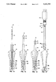
- FIG. 1 is an elevational view, with parts thereof shown in section, of the kit of basic elements used to practice the invention, including the thread forming die, four successive pulling tools, and the gauge;
- FIG. 2 is a cross-sectional elevational view of a modified form of a pulling tool which may be used in the practice of the invention
- FIG. 3 is a cross-sectional elevational view of the upper femur of a leg, wherein the femoral component of a prosthetic hip joint has been removed from a cement mantle within the femur and a new mass of cement is in the process of being injected into the cavity left in the mantle by removal of the component;
- FIG. 4 is a cross-sectional elevational view similar to FIG. 3, illustrating the step of using a thread forming die to form a threaded passage within the mass of new cement injected into the mantle;
- FIG. 5 is a cross-sectional elevational view similar to FIG. 4, illustrating removal of the thread forming die from the mass of new cement to leave a threaded passage therein;
- FIG. 6 is cross-sectional elevational view similar to FIG. 5, illustrating the use of the gauge of the present invention to measure the depth of the threaded passage in the mass of new cement.
- FIG. 7 is a cross-sectional elevational view similar to FIG. 6, illustrating the first of the successive pulling tools at the commencement of being threaded into the passage within the plug comprised of the mass of new cement and the cement of the old mantle;
- FIG. 8 is a cross-sectional elevational view similar to FIG. 7, illustrating the first of the successive pulling tools at the termination of being threaded into the passage within the plug;
- FIG. 9 is a cross-sectional elevational view similar to FIG. 8, illustrating a slap hammer coupled to the first pulling tool and in the process of breaking away and removing a segment of the plug;
- FIG. 10 is a cross-sectional elevational view similar to FIG. 9, illustrating the plug of cement which remains after the step of FIG. 9;
- FIG. 11 is a cross-sectional elevational view similar to FIG. 10, illustrating the second of the successive pulling tools at the commencement of being threaded into the passage within the remaining plug of cement;
- FIG. 12 is a cross-sectional elevational view similar to FIG. 11, illustrating the second of the successive pulling tools at the termination of being threaded into the passage within the remaining plug of cement;
- FIG. 13 is a cross-sectional elevational view similar to FIG. 12, illustrating a slap hammer connected to the second pulling tool and in the process of breaking away and removing a second segment of the plug of cement;
- FIG. 14 is a cross-sectional elevational view similar to FIG. 13, illustrating the gauge in the process of measuring the depth of the threaded passage in the plug of cement remaining after the step of FIG. 13;
- FIG. 15 is a cross-sectional elevational view similar to FIG. 14, illustrating the third of the successive pulling tools at the commencement of being threaded into the passage within the remaining plug of cement;
- FIG. 16 is a cross-sectional elevational view similar to FIG. 15, illustrating the third of the successive pulling tools at the termination of being threaded into the passage within the remaining plug of cement;
- FIG. 17 is a cross-sectional elevational view similar to FIG. 16, illustrating a slap hammer coupled to the third pulling tool and in the process of breaking away and removing a segment of the plug of cement;
- FIG. 18 is a cross-sectional elevational view similar to FIG. 17, illustrating the fourth of the successive pulling tools at the commencement of being threaded into the passage within the remaining plug of cement;
- FIG. 19 is a cross-sectional elevational view similar to FIG. 18, illustrating the fourth of the successive pulling tools at the termination of being threaded into the passage within the remaining plug of cement;
- FIG. 20 is a cross-sectional elevational view similar to FIG. 19, illustrating the fourth pulling tool coupled to a slap hammer and in the process of breaking away and removing the final segment of the plug of cement.
- the kit shown in FIG. 1 includes the following components: thread forming die 10, first successive pulling tool 12, second successive pulling tool 14, third successive pulling tool 16, fourth successive pulling tool 18, and depth gauge 20.
- the die 10 is of the same construction as that of U.S. patent application Ser. No. 467,724 and includes a main portion 22 of a uniform enlarged cross-section and a distal end portion 24 of a reduced cross-section, as compared to that of the main portion. Both the main portion 22 and the distal portion 20 are threaded over their lengths with continuous screw threads of the same pitch (e.g. machine screw pitch 20).
- the top end of the die is provided with a square 26 whereby the die may be turned with a wrench.
- the die may be formed of a metal or a polymer and ideally is provided with a non-stick external surface over the threaded portions.
- the non-stick surface may be a permanent integral part of the die, such as TEFLON, and/or a release coating, such as DOW CORNING 20 of the Dow Corning Corporation of Midland, Mich.
- the pulling tools 12, 14, 16 and 18 are each of a bolt-like construction and fabricated of steel rod, with a polymer sleeve telescopically received thereon.
- the sleeves for the tools 12, 14, 16 and 18 are designated, respectively, by the numerals 28, 30, 32 and 34.
- the tool 12 has a length of four inches, the tool 14 six inches, the tool 16 eight inches and the tool 18 nine inches.
- Each tool terminates in a conical distal end and has a distal portion adjacent said end formed with external machine screw threads.
- the threaded sections formed on the tools 12, 14 and 16 are designated by the numerals 36, 38 and 40, respectively, and have a length of approximately 11/2 inches and an o.d. of 1/4 inch.
- the threaded section of the tool 18 has a length of approximately 3/4 of an inch and an o.d. of 1/8 inch.
- the screw threads on the pulling tools are complemental with the threads formed by the die 10.
- the tools 12, 14, 16 and 18 are formed with unthreaded sections 44, 46, 48 and 50, respectively, above the threaded sections thereof.
- Enlarged hexagonal heads 52, 54, 56 and 58, respectively, are formed on the proximal ends of the tools 12, 14, 16 and 18. The heads provide means whereby torsional and pulling forces may be applied to the tools.
- Stop collars 60, 62, 64 and 66 are fixed, respectively, to the tools 12, 14, 16 and 18.
- the collars serve as markers and abutments for the sleeves 28, 30, 32 and 34.
- the sleeves are proportioned to frictionally engage the pulling tools to an extent sufficient to resist inadvertent sliding movement relative thereto, while permitting such movement in response to external forces applied to the sleeves as they are threaded into a plug of cement.
- This proportioning may be provided by cutting the sleeves from an arcuate length of tubing, whereby each sleeve has an arcuate shape (see the sleeve 28 in FIG. 1) which is straightened as the sleeve is telescoped onto a pulling tool.
- the sleeves 28, 30, 32 and 34 are chosen so that, when engaged with the stop collars, the sleeves will cover only the most proximal screw threads of the tools.
- a surgeon using one of the tools will visually observe the sleeve on the tool approaching the stop collar as the tool is threaded into place. When the sleeve contacts the stop collar, the surgeon will know that the tool is fully threaded into place and that no additional torsional forces should be applied to the tool.
- the sleeves on the tools function to shield the most proximal threads of the tools against being threaded into place in the cement being engaged.
- the tool cannot be threaded against the shoulder provided by the unthreaded portion thereof.
- FIG. 2 shows a modified pulling tool which corresponds to the tool 16, except that the shaft of the tool is threaded over its full length, rather than a limited distal portion.
- the elements of the tool shown in FIG. 2 are designated by numerals corresponding to those used for the tool 16, followed by the subscript "b", as follows: tool 16 b ; sleeve 32 b ; threaded section 40 b ; hexagonal head 56 b ; and stop collar 64 b .
- the tool 16 b operates in the same manner as the aforedescribed tools.
- the sleeve 32 b serves to shield the threads on all but the distal portion of the shaft.
- the tool 16 b has the advantage that it may be fabricated of fully threaded rod stock, without the necessity of providing an unthreaded section on the tool shaft.
- the gauge 20 is provided to measure the depth of the screw threaded passage formed by the die 10.
- the elements of the gauge comprise: an indicator rod 68 having an enlarged diameter proximal portion 70 and a reduced diameter distal portion 72; a tube 74 telescopically received on the rod 68, said tube having an enlarged segment proportioned for slidable receipt of the proximal portion 70 and a reduced diameter segment 78 proportioned for slidable receipt of the distal portion 72; an enlarged tip 80 fixed to the end of the distal portion 72; and, an enlarged handle 82 fixed to the proximal portion 70.
- the external surface of the proximal portion 70 is provided with indicia to indicate the longitudinal position of the rod 68 relative to the tube 74.
- the indicia at the lower end of the proximal portion 70 are designated by the numeral 83 and calibrated to measure screw thread turns.
- the indicia on the upper length of the proximal portion 70 are designated by the numeral 85 and calibrated to measure the number of pulling tools required to fully remove the mantle of cement being worked upon.
- FIGS. 3 to 20 The use of the apparatus in carrying out the method steps is depicted sequentially in FIGS. 3 to 20.
- the femur being worked upon is designated in its entirety by the numeral 84 and is illustrating after the femoral component of a prosthetic hip joint has been removed therefrom for replacement.
- These figures also show that the trochanter of the femur has been removed to facilitate the method.
- FIG. 3 shows the femur 84 after the femoral component of the hip joint has been removed, with the cement mantle 86 which is to be removed left in place within the bone recess within the femur.
- the cavity 88 within the mantle has been cleaned and a reduced diameter extension, designated 90, has been drilled into the distal end of the mantle.
- the top of the mantle has also been cut to provide a horizontal surface, as designated by the numeral 92.
- the first step of preparing the mantle for removal comprises injecting cement into the cavity 88.
- This step is illustrated in FIG. 3 wherein an injection gun 94 is shown injecting cement to the bottom of the cavity through a thin snout 96.
- a vent tube 98 is extended to the bottom of the cavity to assure that air will be vented therefrom and that the cavity will be filled to the bottom.
- the gun and snout are slowly retracted, as depicted by the arrow line in FIG. 3.
- the vent tube 98 would be withdrawn after the reduced diameter extension 90 is adequately filled.
- the mantle 86 is comprised of old methylmethacrylate cement.
- This type of cement is capable of being partially dissolved and softened by the application of new like fluid cement thereto. Accordingly, assuming that the mantle is comprised of such cement, the new cement injected into the cavity 88 would be a like cement and, ultimately, bond to the original mantle and form an integral part thereof.
- FIG. 4 shows the mantle filled with new cement to the level of the horizontal surface 92 and the step of forming a screw threaded passage through the plug of new cement.
- the die 10 has been screwed to essentially the bottom of the cavity to form a screw threaded passage therein. It should also be appreciated that the die is provided with a non-stick coating prior to being so screwed into place, either in the form of an integral surface formed as part of the die and/or a non-stick coating applied to the die.
- FIG. 5 shows the mantle, now in the form of a unitary plug 86 a , after the newly injected cement has cured and formed an integral mass with the mantle.
- the die 10 has been threaded out of the plug, leaving a passage comprised of an enlarged proximal portion 100 and a reduced diameter distal portion 102.
- FIG. 6 shows the gauge 20 in the process of measuring the depth of the passage within the plug 86 a .
- the rod 68 is extended to the bottom of the proximal portion 100 of the passage.
- the rod has a diameter less than the internal diameter of the passage and that the tip 80 has a cross-section less than the portion 100 and greater than the portion 102.
- the tip engages the shoulder between the portions 100 and 102 and the depth being measured by the gauge is actually that of only the portion 100.
- FIGS. 7 and 8 show the first tool 12 in the process of being threaded into place in the mantle plug 86 a .
- the distal threads only of the tool are engaged and the sleeve 28 is engaged with the surface 92.
- FIG. 8 shows the tool 12 threadably engaged with the proximal portion 100 of the passage to the maximum extent desired, as indicated by contact of the sleeve 28 with the stop 60. It will be appreciated that in the process of being threaded from the condition shown in FIG. 7 to that shown in FIG. 8, the surgeon would visually observe the sleeve 28 sliding toward the stop 60 and stop the threading process when the pulling tool reaches the point shown in FIG. 8.
- FIG. 9 shows the tool 12 connected to a slap hammer 104 through a coupling 106.
- pulling force has been applied to the upper portion of the mantle plug 86 a and that portion or segment, designated 86 a1 has been removed from the femur 84.
- Such removal is possible because a methylmethacrylate cement has very little tensile strength and readily fractures upon being subjected to tensile force by the slap hammer.
- FIGS. 11 and 12 show the second pulling tool 14 in the process of being threaded into place in the mantle plug 86 a in essentially the same manner that the first pulling tool is depicted as being threaded into place in FIG. 7 and 8.
- the threading process is at its commencement, with the sleeve 30 against the top surface of the mantle plug.
- FIG. 12 shows the tool 14 threaded into the mantle plug to the full extent desired, as indicated by abutment of the sleeve 30 with the stop 62.
- FIG. 13 shows the slap hammer 104 connected to the tool 14 and the segment 86 a2 as having been removed from the femur by the operation of the slap hammer.
- FIG. 14 shows the gauge 20 in the process of measuring the length of the proximal passage portion 100 remaining after removal of the segment 86 a2 . From this figure, it will be seen that the upper end of the tube 74 registers with the screw thread measuring indicia 83 on the rod 68. This results because the depth of the threads being measured is less than the maximum exposed threads on a pulling tool when the sleeve on the tool is against the stop collar. The resulting measurement on the rod indicates the number of turns required to thread a pulling tool to the bottom of the threaded proximal portion 100, without overtightening.
- FIGS. 15 and 16 illustrate the third pulling tool 16 in the process of being threaded into the remaining cement mantle plug 86 a .
- the threading process is at the commencement stage and the sleeve 32 is against the top of the plug.
- FIG. 16 shows the tool threaded into the plug to the maximum extent and illustrates that the sleeve 32 has not abutted the stop collar 64. The latter condition results because the tool has been threaded into place by the number of turns indicated by the gauge in the step depicted in FIG. 14; and this number of turns results in less than full extension of the threaded section 40 from the sleeve 32.
- FIG. 17 shows the slap hammer 104 connected to the tool 16 and a segment 86 a3 as having been removed from the femur by operation of the slap hammer. As there shown, it will be seen that only the distal portion of the mantle plug remains within the femur.
- FIGS. 18 and 19 depict the step of threading the fourth tool 18 into the final reduced diameter segment of the mantle.
- the process of threading the tool into the mantle segment is at its commencement.
- FIG. 19 shows the tool fully threaded into place, as is apparent from contact of the sleeve 34 with the stop 66. It will be appreciated that during the process moving from the condition shown in FIG. 18 to that of FIG. 19, the surgeon visually observes the sleeve 34 moving toward the stop collar 66 and exercises care not to tighten the tool beyond the point where the sleeve contacts the collar.
- FIG. 20 shows the final step of removing the mantle segment 86 a4 from the femoral cavity.
- the slap hammer 104 is connected to the tool 18 and the plug segment 86 a4 has been removed by operation of the slap hammer.
- the present invention provides an apparatus and method to avoid the overtightening of the tools used for the incremental removal of cement mantles for prosthetic joints.
- the invention provides a means whereby the surgeon may be fully informed in advance of the length of the mantle being removed and the number of steps which will be required for its removal.
Landscapes
- Health & Medical Sciences (AREA)
- Life Sciences & Earth Sciences (AREA)
- Orthopedic Medicine & Surgery (AREA)
- Surgery (AREA)
- Biomedical Technology (AREA)
- Engineering & Computer Science (AREA)
- Nuclear Medicine, Radiotherapy & Molecular Imaging (AREA)
- Heart & Thoracic Surgery (AREA)
- Medical Informatics (AREA)
- Molecular Biology (AREA)
- Animal Behavior & Ethology (AREA)
- General Health & Medical Sciences (AREA)
- Public Health (AREA)
- Veterinary Medicine (AREA)
- Surgical Instruments (AREA)
Abstract
Description
Claims (7)
Priority Applications (7)
| Application Number | Priority Date | Filing Date | Title |
|---|---|---|---|
| US07/475,778 US5152792A (en) | 1990-02-06 | 1990-02-06 | Apparatus and method for gauging and controlling process steps used to remove prosthetic joints |
| AT90630262T ATE134857T1 (en) | 1990-01-19 | 1990-12-21 | DEVICE FOR MEASURING AND CONTROLLING PROCEDURE STEPS FOR REMOVAL OF ARTIFICIAL JOINTS |
| EP90630262A EP0439993B1 (en) | 1990-01-19 | 1990-12-21 | Apparatus for gauging and controlling process steps used to remove prosthethic joints |
| DE69025744T DE69025744T2 (en) | 1990-01-19 | 1990-12-21 | Device for measuring and controlling process steps for removing artificial joints |
| ES90630262T ES2084686T3 (en) | 1990-01-19 | 1990-12-21 | APPARATUS TO CALIBRATE AND CONTROL THE STAGES OF A PROCEDURE USED TO REMOVE PROSTHETIC JOINTS. |
| CA002033925A CA2033925A1 (en) | 1990-01-19 | 1991-01-10 | Apparatus and method for gauging and controlling process steps used to remove prosthetic joints |
| JP3014680A JPH04212351A (en) | 1990-01-19 | 1991-01-14 | Apparatus and method for removing cement mantle from bone depressed part |
Applications Claiming Priority (1)
| Application Number | Priority Date | Filing Date | Title |
|---|---|---|---|
| US07/475,778 US5152792A (en) | 1990-02-06 | 1990-02-06 | Apparatus and method for gauging and controlling process steps used to remove prosthetic joints |
Publications (1)
| Publication Number | Publication Date |
|---|---|
| US5152792A true US5152792A (en) | 1992-10-06 |
Family
ID=23889103
Family Applications (1)
| Application Number | Title | Priority Date | Filing Date |
|---|---|---|---|
| US07/475,778 Expired - Fee Related US5152792A (en) | 1990-01-19 | 1990-02-06 | Apparatus and method for gauging and controlling process steps used to remove prosthetic joints |
Country Status (1)
| Country | Link |
|---|---|
| US (1) | US5152792A (en) |
Cited By (28)
| Publication number | Priority date | Publication date | Assignee | Title |
|---|---|---|---|---|
| US5607431A (en) * | 1995-02-09 | 1997-03-04 | Howmedica Inc. | Prosthetic hip implantation method and apparatus |
| US5743916A (en) * | 1990-07-13 | 1998-04-28 | Human Factors Industrial Design, Inc. | Drill guide with removable ferrules |
| US6015408A (en) * | 1997-07-02 | 2000-01-18 | Howmedica International Inc. | Apparatus for impacting bone chips in a bone canal |
| US6022355A (en) * | 1997-07-02 | 2000-02-08 | Benoist Girard & Cie | Impaction hammer for bone chips |
| US6273895B1 (en) | 1995-06-06 | 2001-08-14 | Corvita Corporation | Method of measuring a body cavity |
| WO2001067032A1 (en) * | 2000-03-09 | 2001-09-13 | James Neill Holdings Limited | Gauge for measuring thread diameters and depths |
| US20050043810A1 (en) * | 2000-04-26 | 2005-02-24 | Dana Mears | Method and apparatus for performing a minimally invasive total hip arthroplasty |
| US20050147478A1 (en) * | 2003-12-30 | 2005-07-07 | Greenberg Alex M. | Sleeved stop for a drill bit |
| US20050177172A1 (en) * | 2000-04-26 | 2005-08-11 | Acker Dean M. | Method and apparatus for performing a minimally invasive total hip arthroplasty |
| US20050240197A1 (en) * | 2004-04-23 | 2005-10-27 | Kmiec Stanley J Jr | Device and method for inserting, positioning and removing an implant |
| US20050245934A1 (en) * | 2004-03-09 | 2005-11-03 | Finsbury (Development) Limited | Tool |
| US20060089649A1 (en) * | 2004-10-26 | 2006-04-27 | Ullrich Peter F Jr | Surgical instruments and method of using same |
| US20070032790A1 (en) * | 2005-08-05 | 2007-02-08 | Felix Aschmann | Apparatus for treating spinal stenosis |
| US20070162038A1 (en) * | 2005-10-18 | 2007-07-12 | Finsbury (Development) Limited | Tool |
| US20070213833A1 (en) * | 2000-04-26 | 2007-09-13 | Zimmer Technology, Inc. | Method and apparatus for performing a minimally invasive total hip arthroplasty |
| US20080275566A1 (en) * | 2007-05-04 | 2008-11-06 | Lewis Randall J | Femoral hip stem explant system |
| US20090012528A1 (en) * | 2005-08-05 | 2009-01-08 | Felix Aschmann | Apparatus for Treating Spinal Stenosis |
| US20090105709A1 (en) * | 2004-04-20 | 2009-04-23 | Finsbury (Development) Limited | Tool |
| US20090112215A1 (en) * | 2007-10-29 | 2009-04-30 | Sherman Jason T | Opto-electric indicators for orthopaedic instruments |
| US20110060373A1 (en) * | 2009-09-09 | 2011-03-10 | Russell Thomas A | Bone screws and methods of use thereof |
| US20110213350A1 (en) * | 2010-03-01 | 2011-09-01 | Bertram Ezenwa | Laser Focused Ablation Apparatus and Method of Use in Revision Arthroplasty |
| US8133231B2 (en) | 2004-07-06 | 2012-03-13 | Tyco Healthcare Group Lp | Instrument kit and method for performing meniscal repair |
| CN103830022A (en) * | 2012-09-20 | 2014-06-04 | 德普伊(爱尔兰)有限公司 | Modular knee prosthesis with multiple lengths of sleeves sharing a common geometry |
| US20150320522A1 (en) * | 2012-06-28 | 2015-11-12 | Jeder Gmbh | Angular connector/milling cutter |
| US20180092633A1 (en) * | 2015-06-02 | 2018-04-05 | Becton, Dickinson And Company | Tissue removal device and method of use |
| US9993276B2 (en) | 2013-03-15 | 2018-06-12 | Innovision, Inc. | Bone screws and methods of use thereof |
| US10485558B1 (en) * | 2015-07-31 | 2019-11-26 | Joshua Cook | Apparatus and method for harvesting bone |
| US10543097B2 (en) | 2012-09-20 | 2020-01-28 | Depuy Ireland Unlimited Company | Method and surgical instrument system with multiple lengths of broaches sharing a common geometry |
Citations (9)
| Publication number | Priority date | Publication date | Assignee | Title |
|---|---|---|---|---|
| US4222382A (en) * | 1979-01-26 | 1980-09-16 | Massachusetts Institute Of Technology | Femoral component hip joint prosthesis extractor |
| US4248232A (en) * | 1977-09-13 | 1981-02-03 | Eckart Engelbrecht | Method of dissolving the bond between interconnected components |
| US4399813A (en) * | 1981-01-22 | 1983-08-23 | Barber Forest C | Apparatus and method for removing a prosthesis embedded in skeletal bone |
| US4463753A (en) * | 1980-01-04 | 1984-08-07 | Gustilo Ramon B | Compression bone screw |
| US4476861A (en) * | 1979-11-06 | 1984-10-16 | Christos Dimakos | Instrument for removal of a bone cement tube in an artificial femur head reimplantation |
| US4686971A (en) * | 1984-11-19 | 1987-08-18 | Harris William H | Method and apparatus for extraction of prostheses |
| US4702236A (en) * | 1986-06-02 | 1987-10-27 | Samih Tarabichy | Revision arthroplasty method and related instrument |
| US4834081A (en) * | 1988-01-11 | 1989-05-30 | Boehringer Mannheim Corporation | Tool for removing modular joint prosthesis |
| US4838264A (en) * | 1987-08-18 | 1989-06-13 | Bremer Orthopedics, Inc. | Torque limiting device for use with bone penetrating pins |
-
1990
- 1990-02-06 US US07/475,778 patent/US5152792A/en not_active Expired - Fee Related
Patent Citations (10)
| Publication number | Priority date | Publication date | Assignee | Title |
|---|---|---|---|---|
| US4248232A (en) * | 1977-09-13 | 1981-02-03 | Eckart Engelbrecht | Method of dissolving the bond between interconnected components |
| US4222382A (en) * | 1979-01-26 | 1980-09-16 | Massachusetts Institute Of Technology | Femoral component hip joint prosthesis extractor |
| US4476861A (en) * | 1979-11-06 | 1984-10-16 | Christos Dimakos | Instrument for removal of a bone cement tube in an artificial femur head reimplantation |
| US4463753A (en) * | 1980-01-04 | 1984-08-07 | Gustilo Ramon B | Compression bone screw |
| US4399813A (en) * | 1981-01-22 | 1983-08-23 | Barber Forest C | Apparatus and method for removing a prosthesis embedded in skeletal bone |
| US4612922A (en) * | 1981-01-22 | 1986-09-23 | Barber Forest C | Drilling apparatus and method |
| US4686971A (en) * | 1984-11-19 | 1987-08-18 | Harris William H | Method and apparatus for extraction of prostheses |
| US4702236A (en) * | 1986-06-02 | 1987-10-27 | Samih Tarabichy | Revision arthroplasty method and related instrument |
| US4838264A (en) * | 1987-08-18 | 1989-06-13 | Bremer Orthopedics, Inc. | Torque limiting device for use with bone penetrating pins |
| US4834081A (en) * | 1988-01-11 | 1989-05-30 | Boehringer Mannheim Corporation | Tool for removing modular joint prosthesis |
Non-Patent Citations (8)
| Title |
|---|
| "Moglichkeiten der Anwendung von Ultraschallwerkzeug bei Endoprothesenwechsel", E. Nieder, E. Engelbrecht, U. Roder und E. Strickle, Der Chirurg, 1979. |
| "Revision in Surgery for Failed, Monseptic Total Hip Arthroplasty-The Femoral Side", William H. Harris, M.D., pp. 8-20. |
| M glichkeiten der Anwendung von Ultraschallwerkzeug bei Endoprothesenwechsel , E. Nieder, E. Engelbrecht, U. R der und E. Strickle, Der Chirurg, 1979. * |
| Revision in Surgery for Failed, Monseptic Total Hip Arthroplasty The Femoral Side , William H. Harris, M.D., pp. 8 20. * |
| Synthes "Original Instruments", Wayne, Pa., Aug. 1984, pp. (1)-7, (1)-8; (3)3-10. |
| Synthes Original Instruments , Wayne, Pa., Aug. 1984, pp. (1) 7, (1) 8; (3)3 10. * |
| Techniques in Orthopedics, "Revision of Total Hip and Knee", Lawrence D. Dorr, M.D., pp. 14-22. |
| Techniques in Orthopedics, Revision of Total Hip and Knee , Lawrence D. Dorr, M.D., pp. 14 22. * |
Cited By (52)
| Publication number | Priority date | Publication date | Assignee | Title |
|---|---|---|---|---|
| US5743916A (en) * | 1990-07-13 | 1998-04-28 | Human Factors Industrial Design, Inc. | Drill guide with removable ferrules |
| US5888034A (en) * | 1990-07-13 | 1999-03-30 | Greenberg; Alex M. | Drill mountable drill guide |
| US5607431A (en) * | 1995-02-09 | 1997-03-04 | Howmedica Inc. | Prosthetic hip implantation method and apparatus |
| US6273895B1 (en) | 1995-06-06 | 2001-08-14 | Corvita Corporation | Method of measuring a body cavity |
| US6022355A (en) * | 1997-07-02 | 2000-02-08 | Benoist Girard & Cie | Impaction hammer for bone chips |
| US6015408A (en) * | 1997-07-02 | 2000-01-18 | Howmedica International Inc. | Apparatus for impacting bone chips in a bone canal |
| WO2001067032A1 (en) * | 2000-03-09 | 2001-09-13 | James Neill Holdings Limited | Gauge for measuring thread diameters and depths |
| US20050043810A1 (en) * | 2000-04-26 | 2005-02-24 | Dana Mears | Method and apparatus for performing a minimally invasive total hip arthroplasty |
| US20070213833A1 (en) * | 2000-04-26 | 2007-09-13 | Zimmer Technology, Inc. | Method and apparatus for performing a minimally invasive total hip arthroplasty |
| US20050177172A1 (en) * | 2000-04-26 | 2005-08-11 | Acker Dean M. | Method and apparatus for performing a minimally invasive total hip arthroplasty |
| US7780673B2 (en) | 2000-04-26 | 2010-08-24 | Zimmer Technology, Inc. | Method and apparatus for performing a minimally invasive total hip arthroplasty |
| US7833275B2 (en) | 2000-04-26 | 2010-11-16 | Zimmer Technology, Inc. | Method and apparatus for performing a minimally invasive total hip arthroplasty |
| US7210881B2 (en) | 2003-12-30 | 2007-05-01 | Greenberg Alex M | Sleeved stop for a drill bit |
| US20050147478A1 (en) * | 2003-12-30 | 2005-07-07 | Greenberg Alex M. | Sleeved stop for a drill bit |
| US20050245934A1 (en) * | 2004-03-09 | 2005-11-03 | Finsbury (Development) Limited | Tool |
| US20090105709A1 (en) * | 2004-04-20 | 2009-04-23 | Finsbury (Development) Limited | Tool |
| US20050240197A1 (en) * | 2004-04-23 | 2005-10-27 | Kmiec Stanley J Jr | Device and method for inserting, positioning and removing an implant |
| US8133231B2 (en) | 2004-07-06 | 2012-03-13 | Tyco Healthcare Group Lp | Instrument kit and method for performing meniscal repair |
| US20060089649A1 (en) * | 2004-10-26 | 2006-04-27 | Ullrich Peter F Jr | Surgical instruments and method of using same |
| US8435242B2 (en) | 2004-10-26 | 2013-05-07 | Orthovita, Inc. | Surgical instruments and method of using same |
| US20080243128A1 (en) * | 2004-10-26 | 2008-10-02 | Vita Licensing | Surgical Instruments And Method Of Using Same |
| US20110224672A1 (en) * | 2004-10-26 | 2011-09-15 | Orthovita, Inc. | Surgical instruments and method of using same |
| US7947044B2 (en) | 2004-10-26 | 2011-05-24 | Orthovita, Inc. | Surgical instruments for shaping spinal endplates |
| US20090012528A1 (en) * | 2005-08-05 | 2009-01-08 | Felix Aschmann | Apparatus for Treating Spinal Stenosis |
| US7753938B2 (en) * | 2005-08-05 | 2010-07-13 | Synthes Usa, Llc | Apparatus for treating spinal stenosis |
| US8870890B2 (en) | 2005-08-05 | 2014-10-28 | DePuy Synthes Products, LLC | Pronged holder for treating spinal stenosis |
| US20070032790A1 (en) * | 2005-08-05 | 2007-02-08 | Felix Aschmann | Apparatus for treating spinal stenosis |
| US20110071534A1 (en) * | 2005-10-18 | 2011-03-24 | Finsbury Instruments, Ltd. | Method of applying a femoral head resurfacing prosthesis |
| US20070162038A1 (en) * | 2005-10-18 | 2007-07-12 | Finsbury (Development) Limited | Tool |
| US9138242B2 (en) | 2007-05-04 | 2015-09-22 | Randall J. Lewis | Femoral hip stem explant system |
| US20080275566A1 (en) * | 2007-05-04 | 2008-11-06 | Lewis Randall J | Femoral hip stem explant system |
| US20090112215A1 (en) * | 2007-10-29 | 2009-04-30 | Sherman Jason T | Opto-electric indicators for orthopaedic instruments |
| US8574273B2 (en) | 2009-09-09 | 2013-11-05 | Innovision, Inc. | Bone screws and methods of use thereof |
| US9936992B2 (en) | 2009-09-09 | 2018-04-10 | Innovision, Inc. | Bone screws and methods of use thereof |
| US11766283B2 (en) | 2009-09-09 | 2023-09-26 | Innovision, Inc. | Bone screws and methods of use thereof |
| US20110060373A1 (en) * | 2009-09-09 | 2011-03-10 | Russell Thomas A | Bone screws and methods of use thereof |
| US9333018B2 (en) | 2009-09-09 | 2016-05-10 | Innovision, Inc. | Bone screws and methods of use thereof |
| US11147603B2 (en) | 2009-09-09 | 2021-10-19 | Zimmer Biomet Spine, Inc. | Bone screws and methods of use thereof |
| WO2011109414A3 (en) * | 2010-03-01 | 2012-01-12 | Wisys Technology Foundation, Inc. | Laser focused ablation apparatus and method of use in revision arthroplasty |
| WO2011109414A2 (en) * | 2010-03-01 | 2011-09-09 | Wisys Technology Foundation, Inc. | Laser focused ablation apparatus and method of use in revision arthroplasty |
| US20110213350A1 (en) * | 2010-03-01 | 2011-09-01 | Bertram Ezenwa | Laser Focused Ablation Apparatus and Method of Use in Revision Arthroplasty |
| US20150320522A1 (en) * | 2012-06-28 | 2015-11-12 | Jeder Gmbh | Angular connector/milling cutter |
| CN103830022B (en) * | 2012-09-20 | 2017-07-11 | 德普伊爱尔兰无限公司 | The modularization knee joint prosthesis system of the sleeve pipe with different lengths |
| US10543097B2 (en) | 2012-09-20 | 2020-01-28 | Depuy Ireland Unlimited Company | Method and surgical instrument system with multiple lengths of broaches sharing a common geometry |
| US10583011B2 (en) | 2012-09-20 | 2020-03-10 | Depuy Ireland Unlimited Company | Method and system including sleeves and broaches for surgically preparing the patient's bone |
| US11648127B2 (en) | 2012-09-20 | 2023-05-16 | Depuy Ireland Unlimited Company | Method and system including sleeves and broaches for surgically preparing the patient's bone |
| CN103830022A (en) * | 2012-09-20 | 2014-06-04 | 德普伊(爱尔兰)有限公司 | Modular knee prosthesis with multiple lengths of sleeves sharing a common geometry |
| US9993276B2 (en) | 2013-03-15 | 2018-06-12 | Innovision, Inc. | Bone screws and methods of use thereof |
| US10751102B2 (en) | 2013-03-15 | 2020-08-25 | Innovision, Inc. | Bone screws and methods of use thereof |
| US20180092633A1 (en) * | 2015-06-02 | 2018-04-05 | Becton, Dickinson And Company | Tissue removal device and method of use |
| US11311278B2 (en) * | 2015-06-02 | 2022-04-26 | Merit Medical Systems, Inc. | Tissue removal device and method of use |
| US10485558B1 (en) * | 2015-07-31 | 2019-11-26 | Joshua Cook | Apparatus and method for harvesting bone |
Similar Documents
| Publication | Publication Date | Title |
|---|---|---|
| US5152792A (en) | Apparatus and method for gauging and controlling process steps used to remove prosthetic joints | |
| US5190551A (en) | Controlled apparatus and method for extracting cement mantles from bone recesses | |
| EP0438515B1 (en) | Pulling appliance for embedment in a mass of fluid cement and kit for removing a mantle of cement | |
| US5156606A (en) | Method and apparatus for removing pre-placed prosthetic joints and preparing for their replacement | |
| US5041120A (en) | Multipart kit and method of using the same to remove cement used to secure prosthetic joints | |
| US2121193A (en) | Fracture clamping apparatus | |
| US5078718A (en) | Multi-part method and apparatus for removing pre-placed prosthetic joints and preparing for their replacement | |
| JP3090646B2 (en) | Bone chipping compression device | |
| US2631584A (en) | Fracture securing instrument | |
| US5562673A (en) | Awls for sizing bone canals | |
| DE2542056C3 (en) | Device for cutting an internal thread in a bone canal to be prepared for receiving the stem of an endoprosthesis | |
| DE69821131T2 (en) | ENDODONTIC DEVICE FOR APPLYING A FILLING MATERIAL ON TOOTH ROOT CHANNELS | |
| DE3800482A1 (en) | Surgical drilling instrument | |
| DE19813328A1 (en) | Device for handling ball heads of joint prostheses | |
| US20160199145A1 (en) | Method and apparatus for measurement of intramedullary length with radiopaque markings | |
| US5222958A (en) | Apparatus for removing pre-placed prosthetic joints | |
| EP0439993B1 (en) | Apparatus for gauging and controlling process steps used to remove prosthethic joints | |
| US4800873A (en) | Method for setting fractures | |
| DE60104184T2 (en) | BONE GRAFT COMPRESSOR | |
| US20070233154A1 (en) | Tool for removing broken intramedullary rods | |
| EP0520293B1 (en) | Apparatus for extracting a cement mantle from a bone recess | |
| US5222957A (en) | Method and apparatus for extracting a cement mantle from a bone recess | |
| DE202007007322U1 (en) | Set of instruments for the minimally invasive preparation of a bone nailing | |
| DE20316629U1 (en) | Surgical slide hammer for removing medullary nails has exchangeable expansion tips with different surfaces to engage ends of nails | |
| CA2013746C (en) | Method and apparatus for removing pre-placed prosthetic joints and preparing for their replacement |
Legal Events
| Date | Code | Title | Description |
|---|---|---|---|
| AS | Assignment |
Owner name: ORIGIN MEDSYSTEMS, INC., CALIFORNIA Free format text: ASSIGNMENT OF ASSIGNORS INTEREST.;ASSIGNORS:WATKINS, F. THOMAS;CHIN, ALBERT K.;REEL/FRAME:005229/0203 Effective date: 19900205 |
|
| AS | Assignment |
Owner name: ZIMMER, INC., INDIANA Free format text: ASSIGNMENT OF ASSIGNORS INTEREST.;ASSIGNOR:ORIGIN MEDSYSTEMS, INC.;REEL/FRAME:006269/0035 Effective date: 19920625 |
|
| FPAY | Fee payment |
Year of fee payment: 4 |
|
| AS | Assignment |
Owner name: LINVATEC CORPORATION, FLORIDA Free format text: ASSIGNMENT OF ASSIGNORS INTEREST;ASSIGNOR:ZIMMER, INC.;REEL/FRAME:008753/0732 Effective date: 19971002 |
|
| FEPP | Fee payment procedure |
Free format text: PAYOR NUMBER ASSIGNED (ORIGINAL EVENT CODE: ASPN); ENTITY STATUS OF PATENT OWNER: LARGE ENTITY |
|
| FPAY | Fee payment |
Year of fee payment: 8 |
|
| REMI | Maintenance fee reminder mailed | ||
| LAPS | Lapse for failure to pay maintenance fees | ||
| STCH | Information on status: patent discontinuation |
Free format text: PATENT EXPIRED DUE TO NONPAYMENT OF MAINTENANCE FEES UNDER 37 CFR 1.362 |
|
| FP | Lapsed due to failure to pay maintenance fee |
Effective date: 20041006 |