US5149965A - Precision radiography scaling device - Google Patents
Precision radiography scaling device Download PDFInfo
- Publication number
- US5149965A US5149965A US07/512,844 US51284490A US5149965A US 5149965 A US5149965 A US 5149965A US 51284490 A US51284490 A US 51284490A US 5149965 A US5149965 A US 5149965A
- Authority
- US
- United States
- Prior art keywords
- sphere
- image field
- dimension
- target structure
- radiograph
- Prior art date
- Legal status (The legal status is an assumption and is not a legal conclusion. Google has not performed a legal analysis and makes no representation as to the accuracy of the status listed.)
- Expired - Lifetime
Links
Images

Classifications
-
- A—HUMAN NECESSITIES
- A61—MEDICAL OR VETERINARY SCIENCE; HYGIENE
- A61B—DIAGNOSIS; SURGERY; IDENTIFICATION
- A61B6/00—Apparatus for radiation diagnosis, e.g. combined with radiation therapy equipment
- A61B6/58—Testing, adjusting or calibrating apparatus or devices for radiation diagnosis
- A61B6/582—Calibration
- A61B6/583—Calibration using calibration phantoms
-
- G—PHYSICS
- G01—MEASURING; TESTING
- G01N—INVESTIGATING OR ANALYSING MATERIALS BY DETERMINING THEIR CHEMICAL OR PHYSICAL PROPERTIES
- G01N23/00—Investigating or analysing materials by the use of wave or particle radiation, e.g. X-rays or neutrons, not covered by groups G01N3/00 – G01N17/00, G01N21/00 or G01N22/00
- G01N23/02—Investigating or analysing materials by the use of wave or particle radiation, e.g. X-rays or neutrons, not covered by groups G01N3/00 – G01N17/00, G01N21/00 or G01N22/00 by transmitting the radiation through the material
- G01N23/04—Investigating or analysing materials by the use of wave or particle radiation, e.g. X-rays or neutrons, not covered by groups G01N3/00 – G01N17/00, G01N21/00 or G01N22/00 by transmitting the radiation through the material and forming images of the material
-
- A—HUMAN NECESSITIES
- A61—MEDICAL OR VETERINARY SCIENCE; HYGIENE
- A61B—DIAGNOSIS; SURGERY; IDENTIFICATION
- A61B6/00—Apparatus for radiation diagnosis, e.g. combined with radiation therapy equipment
- A61B6/50—Clinical applications
- A61B6/508—Clinical applications for non-human patients
Definitions
- the invention relates to devices and methods for scaling radiographic images and particularly to devices and methods which facilitate scaling in multiple views.
- Catheters, grids of known dimensions and radiopaque cubes of known dimensions are all commonly used as radiography scaling devices, but all have certain inherent disadvantages. If a catheter of known diameter is in the picture, this may be used. However, the catheter must be at the same location as the structure to be imaged, preferably through the structure to be imaged, or an unknown magnification error will result. For more precise measurement, a picture of a grid or a radiopaque cube of known dimensions may be imaged. For the image to be useful, the grid should be the same distance from the imaging beam as the body structure to be measured, and the grid must be positioned so that its known dimension is perpendicular to the imaging beam.
- the reference object is important for the reference object to be positioned in the same relative position in three dimensional space, with reference to two imaging beams, as the body structure was when the image of the structure was taken. This requires positioning the reference object accurately in order for it to appear in the same place as the body structure on both images simultaneously.
- the catheter diameter is the known image dimension. If a catheter diameter is used as the reference dimension, there may be an inherent inaccuracy unless the catheter is adjacent to or through the body structure being measured, so that it is accurately positioned at the location of interest. Also, because the images of the edges of plastic catheters tend to fade and the catheter casts an image with a small diameter, it may be difficult to precisely measure the catheter diameter. Accordingly, a catheter diameter is an inherently poor reference object.
- At least one radiopaque sphere is used for scaling radiographic images.
- the sphere is of known dimensions and includes means for positioning the sphere in any location of the image field.
- the invention also includes a method for producing multiple images, simultaneously from a radiopaque sphere, and a method of scaling images by comparing the images produced to at least one image of a radiopaque sphere.
- FIG. 1 illustrates an image-scaling sphere encased in a plastic cube.
- FIG. 2 illustrates a plurality of spheres of different sizes encased in a plastic rectangular solid to dispose the spheres at spaced locations in an image field.
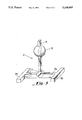
- FIG. 3 illustrates a sphere attached to a mechanical device to position the sphere in three dimensions of the image field.
- images of internal body structures are produced by electromagnetic radiation using techniques including x-rays and nuclear magnetic resonance.
- a device and method for scaling images including straight AP and lateral.
- FIG. 1 there is shown an embodiment comprising a sphere 20 of steel or some other radiopaque material, and a sphere-encasing cube 21 composed of plastic, such as a Lucite or plexiglas or some other material of differential radiopacity compared to the sphere.
- Cube 21 may be held in place in the image field by a laboratory clamp, also with a differential radiopacity, or by placing it on surface of the radiography field to be imaged, thus providing a means for positioning cube 21.
- FIG. 2 is an alternative to the embodiment of FIG. 1, and allows spheres to be placed at spaced locations in the image field.
- a plastic rectangular solid 13 encases several radiopaque spheres 10-12 of different sizes, and may be placed along the horizontal or vertical axis of the image field and held in place in the image field.
- the diameters of the spheres differ from one another by a factor of two, in order to accurately discern the spheres from each other and for use as the scaling reference.
- the length of the plastic may be equal to the diameter of the image field; however, smaller size variations in the length of the rectangle are also acceptable to account for scaling structures at intermediate points between the center and periphery of the image field.
- FIG. 3 there is shown a radiopaque sphere 30, with a three-dimensional positioning device 32.
- Sphere 30 is slidably mounted on holding arm 34 of positioning device 32.
- Arm 34 is rotatably mounted through screw wheel 36 to a base member comprised of a cross piece 38a and outboard stabilizer members 38b, which supports arm 34 and prevents collapse.
- Screw wheel 36 which is frictionally retained in member 38a, and the sliding, but frictionally retained mounting of sphere 30 on arm 34, allows positioning of movable arm 34 and sphere 30 for placement of sphere 30 in essentially any location in the three dimensions of the image field.
- sphere 30, as shown in FIG. 3, or a sphere retaining cube (21 in FIG. 1) or a spheres-retaining solid (13 in FIG. 2) may be positioned in a radiographic image field by a holder associated with (either by being attached to or an extension of) one of the other pieces of equipment used in the imaging operation, such as the table supporting the patient or the mechanical means for supporting X-ray equipment by which the images are generated.
- the sphere of FIG. 1 may be employed in methods of scaling images by comparing an image of a radiographed object to at least one image of a radiopaque sphere.
- the sphere is positioned in the same location as the structure to be imaged as seen from two views. This assures that the sphere is placed at the same position in the three dimensional space relative to the imaging beams and the body structure to be imaged.
- the sphere of FIG. 1 may simply be placed loosely into the retaining cube (or rectangular solid) or may be held therein by a jelled semi-solid.
- the sphere may also be held in place in the image field by a laboratory clamp with differential radiopacity than the sphere, or by placing it on surface of the radiography field to be imaged.
- sphere(s) of FIG. 2-3 may be used.
- the device of FIG. 3 When scaling structures at intermediate points between the center and the periphery of the image field, the device of FIG. 3 may be used as the sphere 30 may be placed at any location in the three dimensions of the image field.
- the sphere nearest to the location of the imaged structure and identifiable from two different angles is to be employed as the reference for scaling.
- Spheres of various sizes may be used in the embodiment of FIG. 3 to accurately identify the sphere used as the scaling reference. Increasing the diameters of the spheres by a factor of two accurately discerns the sphere used as the reference. This method provides an accurate reference for scaling structures by accounting for magnification differences across the image field.
- the sphere(s) may also be used as a reference scaling device in a method to produce simultaneous images.
- the sphere(s) need not be repositioned for non-simultaneous imaging but serves instead, with a single placement, for scaling reference in simultaneously taken views. Accordingly, two radiographic cameras may be employed at the same time.
- the target structure is placed in the image field and images are taken with the radiographic device(s).
- An object of known spherical dimension is placed in the image field in the same location previously occupied by the target structure, such that the object appears in the same location in at least two views as the structure to be measured, and radiographs are made via the radiographic device(s).
- Scaling is accomplished by comparing a first dimension to be determined of the target structure to the known dimension of the spherical object made by the same device that produced the image in which the dimension is to be determined.
- the means for positioning the sphere such as the cube and laboratory clamp, are disclosed as having differential radiopacity compared to the sphere. Varying the radiopacity is necessary to accurately discern the sphere from the means for positioning as well as for precise scaling.
- the sphere may be more or less radiopaque than the means for positioning as either would depict the sphere as a discernable scaling reference.
Abstract
Description
Claims (10)
Priority Applications (3)
| Application Number | Priority Date | Filing Date | Title |
|---|---|---|---|
| US07/512,844 US5149965A (en) | 1990-04-23 | 1990-04-23 | Precision radiography scaling device |
| AU78722/91A AU7872291A (en) | 1990-04-23 | 1991-04-15 | Precision radiography scaling device |
| PCT/US1991/002617 WO1991016620A1 (en) | 1990-04-23 | 1991-04-15 | Precision radiography scaling device |
Applications Claiming Priority (1)
| Application Number | Priority Date | Filing Date | Title |
|---|---|---|---|
| US07/512,844 US5149965A (en) | 1990-04-23 | 1990-04-23 | Precision radiography scaling device |
Publications (1)
| Publication Number | Publication Date |
|---|---|
| US5149965A true US5149965A (en) | 1992-09-22 |
Family
ID=24040815
Family Applications (1)
| Application Number | Title | Priority Date | Filing Date |
|---|---|---|---|
| US07/512,844 Expired - Lifetime US5149965A (en) | 1990-04-23 | 1990-04-23 | Precision radiography scaling device |
Country Status (3)
| Country | Link |
|---|---|
| US (1) | US5149965A (en) |
| AU (1) | AU7872291A (en) |
| WO (1) | WO1991016620A1 (en) |
Cited By (24)
| Publication number | Priority date | Publication date | Assignee | Title |
|---|---|---|---|---|
| US5442674A (en) * | 1993-01-27 | 1995-08-15 | Ge Medical Systems | Device and automatic method for the geometrical calibration of an X-ray imaging system |
| WO1997031570A1 (en) * | 1996-02-29 | 1997-09-04 | Calluna Idé Ab | Device for visual measurement of dimensions |
| US5848125A (en) * | 1997-10-03 | 1998-12-08 | Arnett Facial Reconstruction Courses, Inc. | Radiopaque landmark skin markers and method |
| DE19716519A1 (en) * | 1997-04-03 | 1999-06-17 | Rainer Herzog | X-ray imaging system, especially for dental diagnostics |
| WO2000058691A1 (en) * | 1999-03-18 | 2000-10-05 | Eisenlohr Technologies, Inc. | Radiographic reference marker |
| US20040034298A1 (en) * | 2002-08-13 | 2004-02-19 | Scimed Life Systems, Inc. | Radiographic sizing tool |
| US6739751B2 (en) * | 2001-04-10 | 2004-05-25 | Ge Medical Systems Global Technology Company, Llc | X-ray system alignment method and apparatus |
| DE10318444A1 (en) * | 2003-04-24 | 2004-11-11 | Endress + Hauser Gmbh + Co. Kg | Image quality indicator (IQI) for radiographic material testing, especially non-destructive testing of industrial components, comprises a series of spheres of diameter less than 1mm mounted on a support film |
| US20050157847A1 (en) * | 2003-11-24 | 2005-07-21 | The Regents Of The University Of Michigan | Universal radiologic patient positioning marker |
| EP1760457A2 (en) * | 2005-07-13 | 2007-03-07 | Carl Zeiss Industrielle Messtechnik GmbH | Method and a system for calibrating a measuring apparatus |
| GB2438470A (en) * | 2006-05-25 | 2007-11-28 | Simon Wimsey | Pelvic Radiograph Scaling Device |
| US20080273665A1 (en) * | 2007-05-04 | 2008-11-06 | Michael Rolle | Adjustable Radiographic Marker and Calibration Aid |
| US20080292063A1 (en) * | 2007-04-23 | 2008-11-27 | J2 Medical Solutions Llc | Radiographic Calibration Apparatus |
| US20090185038A1 (en) * | 2008-01-21 | 2009-07-23 | Hartmut Boessmann | Caliberation element for calibrating the magnification ratio of a camera, and a calibration method |
| US7714217B2 (en) | 2007-12-21 | 2010-05-11 | Innovatech, Llc | Marked precoated strings and method of manufacturing same |
| US7811623B2 (en) | 2007-12-21 | 2010-10-12 | Innovatech, Llc | Marked precoated medical device and method of manufacturing same |
| US8048471B2 (en) | 2007-12-21 | 2011-11-01 | Innovatech, Llc | Marked precoated medical device and method of manufacturing same |
| US8231927B2 (en) | 2007-12-21 | 2012-07-31 | Innovatech, Llc | Marked precoated medical device and method of manufacturing same |
| US8231926B2 (en) | 2007-12-21 | 2012-07-31 | Innovatech, Llc | Marked precoated medical device and method of manufacturing same |
| US8900652B1 (en) | 2011-03-14 | 2014-12-02 | Innovatech, Llc | Marked fluoropolymer surfaces and method of manufacturing same |
| WO2015022067A1 (en) | 2013-08-14 | 2015-02-19 | Spontech Spine Gmbh | X-ray image reference marker having an indication of the direction of gravity and computer-implemented method for more accurately determining the position of x-ray images during their capture and for outputting related parameters |
| US9682514B2 (en) | 2010-06-25 | 2017-06-20 | The Boeing Company | Method of manufacturing resin infused composite parts using a perforated caul sheet |
| US20180038779A1 (en) * | 2016-08-05 | 2018-02-08 | General Electric Company | Embedded strain sensor network |
| DE102016225254A1 (en) * | 2016-12-16 | 2018-06-21 | Conti Temic Microelectronic Gmbh | Method for calibrating an X-ray inspection system |
Families Citing this family (2)
| Publication number | Priority date | Publication date | Assignee | Title |
|---|---|---|---|---|
| US5281232A (en) * | 1992-10-13 | 1994-01-25 | Board Of Regents Of The University Of Arizona/ University Of Arizona | Reference frame for stereotactic radiosurgery using skeletal fixation |
| GB9323259D0 (en) * | 1993-11-11 | 1994-01-05 | Armstrong Projects Ltd | Improvements in or relating to alignment apparatus |
Citations (17)
| Publication number | Priority date | Publication date | Assignee | Title |
|---|---|---|---|---|
| US1396920A (en) * | 1921-11-15 | bbostboih | ||
| US2650308A (en) * | 1953-08-25 | Method of and apparatus foe ascer | ||
| US3217705A (en) * | 1962-05-02 | 1965-11-16 | Orman B Billings | Device for testing internal bleeding |
| US3687142A (en) * | 1970-10-06 | 1972-08-29 | Saul Leibinzohn | Catheter |
| US3706883A (en) * | 1969-11-21 | 1972-12-19 | Kevin M Mcintyre | Radiological apparatus for measuring length which comprises two relatively movable radio opaque marks |
| US3770956A (en) * | 1971-12-30 | 1973-11-06 | Buckbee Mears Co | X-ray measuring grid |
| US3807390A (en) * | 1972-12-04 | 1974-04-30 | American Optical Corp | Fiber optic catheter |
| US3836776A (en) * | 1973-03-01 | 1974-09-17 | E Gullekson | Three dimensional x-ray opaque foreign body marker device |
| US3887804A (en) * | 1973-12-03 | 1975-06-03 | Us Health | Radiographic test stand |
| US4005527A (en) * | 1975-12-22 | 1977-02-01 | Wilson Ralph S | Depth gauge |
| US4181859A (en) * | 1977-04-08 | 1980-01-01 | Pier Luigi Vitalini | Reticle device applicable to flexible radiographic films |
| US4279252A (en) * | 1979-08-24 | 1981-07-21 | Martin Michael T | X-ray scaling catheter |
| US4286168A (en) * | 1979-01-18 | 1981-08-25 | Atomic Products Corp. | Phantom simulation device for scintillation cameras |
| US4442534A (en) * | 1981-07-17 | 1984-04-10 | Siemens Aktiengesellschaft | X-Ray diagnostic installation for X-ray tomographic images |
| US4459990A (en) * | 1982-01-26 | 1984-07-17 | Elscint, Incorporated | Radiographic method and apparatus for the visualization of the interior of a body particularly useful for the visualization of a subject's circulatory system |
| US4671291A (en) * | 1986-03-31 | 1987-06-09 | Siemens Medical Systems, Inc. | Angle encoding catheter |
| US4692936A (en) * | 1984-06-04 | 1987-09-08 | Billeaudeaux James K | Method and apparatus for radiographic inspection |
-
1990
- 1990-04-23 US US07/512,844 patent/US5149965A/en not_active Expired - Lifetime
-
1991
- 1991-04-15 WO PCT/US1991/002617 patent/WO1991016620A1/en unknown
- 1991-04-15 AU AU78722/91A patent/AU7872291A/en not_active Abandoned
Patent Citations (17)
| Publication number | Priority date | Publication date | Assignee | Title |
|---|---|---|---|---|
| US1396920A (en) * | 1921-11-15 | bbostboih | ||
| US2650308A (en) * | 1953-08-25 | Method of and apparatus foe ascer | ||
| US3217705A (en) * | 1962-05-02 | 1965-11-16 | Orman B Billings | Device for testing internal bleeding |
| US3706883A (en) * | 1969-11-21 | 1972-12-19 | Kevin M Mcintyre | Radiological apparatus for measuring length which comprises two relatively movable radio opaque marks |
| US3687142A (en) * | 1970-10-06 | 1972-08-29 | Saul Leibinzohn | Catheter |
| US3770956A (en) * | 1971-12-30 | 1973-11-06 | Buckbee Mears Co | X-ray measuring grid |
| US3807390A (en) * | 1972-12-04 | 1974-04-30 | American Optical Corp | Fiber optic catheter |
| US3836776A (en) * | 1973-03-01 | 1974-09-17 | E Gullekson | Three dimensional x-ray opaque foreign body marker device |
| US3887804A (en) * | 1973-12-03 | 1975-06-03 | Us Health | Radiographic test stand |
| US4005527A (en) * | 1975-12-22 | 1977-02-01 | Wilson Ralph S | Depth gauge |
| US4181859A (en) * | 1977-04-08 | 1980-01-01 | Pier Luigi Vitalini | Reticle device applicable to flexible radiographic films |
| US4286168A (en) * | 1979-01-18 | 1981-08-25 | Atomic Products Corp. | Phantom simulation device for scintillation cameras |
| US4279252A (en) * | 1979-08-24 | 1981-07-21 | Martin Michael T | X-ray scaling catheter |
| US4442534A (en) * | 1981-07-17 | 1984-04-10 | Siemens Aktiengesellschaft | X-Ray diagnostic installation for X-ray tomographic images |
| US4459990A (en) * | 1982-01-26 | 1984-07-17 | Elscint, Incorporated | Radiographic method and apparatus for the visualization of the interior of a body particularly useful for the visualization of a subject's circulatory system |
| US4692936A (en) * | 1984-06-04 | 1987-09-08 | Billeaudeaux James K | Method and apparatus for radiographic inspection |
| US4671291A (en) * | 1986-03-31 | 1987-06-09 | Siemens Medical Systems, Inc. | Angle encoding catheter |
Non-Patent Citations (2)
| Title |
|---|
| "Clin Orthop (121)", 83-91, 1976 Clark et al., Improved Methods for Quantitative Radio Graphic Evaluation. |
| Clin Orthop (121) , 83 91, 1976 Clark et al., Improved Methods for Quantitative Radio Graphic Evaluation. * |
Cited By (43)
| Publication number | Priority date | Publication date | Assignee | Title |
|---|---|---|---|---|
| US5442674A (en) * | 1993-01-27 | 1995-08-15 | Ge Medical Systems | Device and automatic method for the geometrical calibration of an X-ray imaging system |
| WO1997031570A1 (en) * | 1996-02-29 | 1997-09-04 | Calluna Idé Ab | Device for visual measurement of dimensions |
| US6084941A (en) * | 1996-02-29 | 2000-07-04 | Calluna Ide Ab | Device for visual measurement of dimensions |
| DE19716519A1 (en) * | 1997-04-03 | 1999-06-17 | Rainer Herzog | X-ray imaging system, especially for dental diagnostics |
| US5848125A (en) * | 1997-10-03 | 1998-12-08 | Arnett Facial Reconstruction Courses, Inc. | Radiopaque landmark skin markers and method |
| WO2000058691A1 (en) * | 1999-03-18 | 2000-10-05 | Eisenlohr Technologies, Inc. | Radiographic reference marker |
| US6459772B1 (en) * | 1999-03-18 | 2002-10-01 | Eisenlohr Technologies, Inc. | Radiographic reference marker |
| US6739751B2 (en) * | 2001-04-10 | 2004-05-25 | Ge Medical Systems Global Technology Company, Llc | X-ray system alignment method and apparatus |
| US20040034298A1 (en) * | 2002-08-13 | 2004-02-19 | Scimed Life Systems, Inc. | Radiographic sizing tool |
| DE10318444A1 (en) * | 2003-04-24 | 2004-11-11 | Endress + Hauser Gmbh + Co. Kg | Image quality indicator (IQI) for radiographic material testing, especially non-destructive testing of industrial components, comprises a series of spheres of diameter less than 1mm mounted on a support film |
| US20050157847A1 (en) * | 2003-11-24 | 2005-07-21 | The Regents Of The University Of Michigan | Universal radiologic patient positioning marker |
| US7092492B2 (en) * | 2003-11-24 | 2006-08-15 | Regents Of The University Of Michigan | Universal radiologic patient positioning marker |
| EP1760457A2 (en) * | 2005-07-13 | 2007-03-07 | Carl Zeiss Industrielle Messtechnik GmbH | Method and a system for calibrating a measuring apparatus |
| EP1760457A3 (en) * | 2005-07-13 | 2009-11-18 | Carl Zeiss Industrielle Messtechnik GmbH | Method and a system for calibrating a measuring apparatus |
| GB2438470A (en) * | 2006-05-25 | 2007-11-28 | Simon Wimsey | Pelvic Radiograph Scaling Device |
| GB2438470B (en) * | 2006-05-25 | 2011-06-08 | Simon Wimsey | Pelvic radiograph scaling device |
| US20080292063A1 (en) * | 2007-04-23 | 2008-11-27 | J2 Medical Solutions Llc | Radiographic Calibration Apparatus |
| US7960686B2 (en) * | 2007-04-23 | 2011-06-14 | J2 Medical, Lp | Radiographic calibration apparatus |
| US20080273665A1 (en) * | 2007-05-04 | 2008-11-06 | Michael Rolle | Adjustable Radiographic Marker and Calibration Aid |
| US7923617B2 (en) | 2007-12-21 | 2011-04-12 | Innovatech Llc | Marked precoated strings and method of manufacturing same |
| US8772614B2 (en) | 2007-12-21 | 2014-07-08 | Innovatech, Llc | Marked precoated strings and method of manufacturing same |
| US9355621B2 (en) | 2007-12-21 | 2016-05-31 | Innovatech, Llc | Marked precoated strings and method of manufacturing same |
| US7714217B2 (en) | 2007-12-21 | 2010-05-11 | Innovatech, Llc | Marked precoated strings and method of manufacturing same |
| US10573280B2 (en) | 2007-12-21 | 2020-02-25 | Innovatech, Llc | Marked precoated strings and method of manufacturing same |
| US8048471B2 (en) | 2007-12-21 | 2011-11-01 | Innovatech, Llc | Marked precoated medical device and method of manufacturing same |
| US8231927B2 (en) | 2007-12-21 | 2012-07-31 | Innovatech, Llc | Marked precoated medical device and method of manufacturing same |
| US8231926B2 (en) | 2007-12-21 | 2012-07-31 | Innovatech, Llc | Marked precoated medical device and method of manufacturing same |
| US8362344B2 (en) | 2007-12-21 | 2013-01-29 | Innovatech, Llc | Marked precoated strings and method of manufacturing same |
| US8574171B2 (en) | 2007-12-21 | 2013-11-05 | Innovatech, Llc | Marked precoated medical device and method of manufacturing same |
| US9782569B2 (en) | 2007-12-21 | 2017-10-10 | Innovatech, Llc | Marked precoated medical device and method of manufacturing same |
| US7811623B2 (en) | 2007-12-21 | 2010-10-12 | Innovatech, Llc | Marked precoated medical device and method of manufacturing same |
| US8940357B2 (en) | 2007-12-21 | 2015-01-27 | Innovatech Llc | Marked precoated medical device and method of manufacturing same |
| US20090185038A1 (en) * | 2008-01-21 | 2009-07-23 | Hartmut Boessmann | Caliberation element for calibrating the magnification ratio of a camera, and a calibration method |
| US7952625B2 (en) * | 2008-01-21 | 2011-05-31 | Texmag Gmbh Vertriebsgesellschaft | Calibration element for calibrating the magnification ratio of a camera, and a calibration method |
| US9682514B2 (en) | 2010-06-25 | 2017-06-20 | The Boeing Company | Method of manufacturing resin infused composite parts using a perforated caul sheet |
| US8900652B1 (en) | 2011-03-14 | 2014-12-02 | Innovatech, Llc | Marked fluoropolymer surfaces and method of manufacturing same |
| US9744271B2 (en) | 2011-03-14 | 2017-08-29 | Innovatech, Llc | Marked fluoropolymer surfaces and method of manufacturing same |
| US9962470B2 (en) | 2011-03-14 | 2018-05-08 | Innovatech, Llc | Marked fluoropolymer surfaces and method of manufacturing same |
| US10111987B2 (en) | 2011-03-14 | 2018-10-30 | Innovatech, Llc | Marked fluoropolymer surfaces and method of manufacturing same |
| WO2015022067A1 (en) | 2013-08-14 | 2015-02-19 | Spontech Spine Gmbh | X-ray image reference marker having an indication of the direction of gravity and computer-implemented method for more accurately determining the position of x-ray images during their capture and for outputting related parameters |
| US20180038779A1 (en) * | 2016-08-05 | 2018-02-08 | General Electric Company | Embedded strain sensor network |
| DE102016225254A1 (en) * | 2016-12-16 | 2018-06-21 | Conti Temic Microelectronic Gmbh | Method for calibrating an X-ray inspection system |
| DE102016225254B4 (en) | 2016-12-16 | 2023-07-06 | Vitesco Technologies Germany Gmbh | Procedure for calibrating an X-ray inspection system |
Also Published As
| Publication number | Publication date |
|---|---|
| AU7872291A (en) | 1991-11-11 |
| WO1991016620A1 (en) | 1991-10-31 |
Similar Documents
| Publication | Publication Date | Title |
|---|---|---|
| US5149965A (en) | Precision radiography scaling device | |
| US5792146A (en) | Rectilinear linac phantom pointer system | |
| US3577160A (en) | X-ray gauging apparatus with x-ray opaque markers in the x-ray path to indicate alignment of x-ray tube, subject and film | |
| US3294083A (en) | Dosimetry system for penetrating radiation | |
| US5872829A (en) | Method for the detection and correction of image distortions in medical imaging | |
| US4341220A (en) | Stereotactic surgery apparatus and method | |
| US5080100A (en) | System and method for measuring and/or checking the position of a patient in a radio-therapy machine | |
| US7264397B2 (en) | Method and x-ray system for determination of position of an x-ray source relative to an x-ray image detector | |
| US5964715A (en) | Method for modifying at least one calculation algorithm in a biopsy system, and biopsy system operating according to the method | |
| EP1417931A1 (en) | Method for automatically producing true size radiographic image | |
| US6671349B1 (en) | Tomosynthesis system and registration method | |
| EP0796059B1 (en) | Determining a dimension from a density distribution | |
| US4349917A (en) | Tomographic method and apparatus | |
| US7157696B2 (en) | Test object for calibration of imaging measurements of mammalian skeletal joints | |
| Leung et al. | Evaluation of catheters and metallic catheter markers as calibration standard for measurement of coronary dimension | |
| US5999591A (en) | Measuring instrument and measuring method | |
| US7241045B2 (en) | Stereoradiography device and method for the use thereof | |
| JP2002529187A (en) | Phantom for X-ray computed tomography | |
| van Kleffens et al. | Application of stereo X-ray photogrammetry (SRM) in the determination of absorbed dose values during intracavitary radiation therapy | |
| US3887804A (en) | Radiographic test stand | |
| US4267641A (en) | Radiographic film inclinometer | |
| DE10139500C1 (en) | Method to determine focus point of X-ray beam source of X-ray unit having C-arm, using images of test absorber located in X-ray source housing | |
| Wilk | Axial transverse tomography of the chest | |
| JPH03502658A (en) | Interface device between MRI and other visual physical therapy | |
| SU1337747A1 (en) | Standard for roentgen densitometry |
Legal Events
| Date | Code | Title | Description |
|---|---|---|---|
| AS | Assignment |
Owner name: TEMPLE UNIVERSITY, PENNSYLVANIA Free format text: ASSIGNMENT OF ASSIGNORS INTEREST.;ASSIGNOR:MARKS, LLOYD A.;REEL/FRAME:005298/0017 Effective date: 19900220 |
|
| STCF | Information on status: patent grant |
Free format text: PATENTED CASE |
|
| FEPP | Fee payment procedure |
Free format text: PAYOR NUMBER ASSIGNED (ORIGINAL EVENT CODE: ASPN); ENTITY STATUS OF PATENT OWNER: SMALL ENTITY Free format text: PAT HOLDER CLAIMS SMALL ENTITY STATUS - SMALL BUSINESS (ORIGINAL EVENT CODE: SM02); ENTITY STATUS OF PATENT OWNER: SMALL ENTITY |
|
| FPAY | Fee payment |
Year of fee payment: 4 |
|
| AS | Assignment |
Owner name: MARKS, LLOYD A., NEW JERSEY Free format text: ASSIGNMENT OF ASSIGNORS INTEREST;ASSIGNOR:TEMPLE UNIVERSITY OF THE COMMONWEALTH SYSTEM OF HIGHER EDUCATION, THE;REEL/FRAME:007919/0584 Effective date: 19960415 |
|
| FPAY | Fee payment |
Year of fee payment: 8 |
|
| FPAY | Fee payment |
Year of fee payment: 12 |