US5138894A - Axial loading cam arrangement in or for a traction roller transmission - Google Patents
Axial loading cam arrangement in or for a traction roller transmission Download PDFInfo
- Publication number
- US5138894A US5138894A US07/817,057 US81705792A US5138894A US 5138894 A US5138894 A US 5138894A US 81705792 A US81705792 A US 81705792A US 5138894 A US5138894 A US 5138894A
- Authority
- US
- United States
- Prior art keywords
- races
- cam
- thrust
- axial
- thrust members
- Prior art date
- Legal status (The legal status is an assumption and is not a legal conclusion. Google has not performed a legal analysis and makes no representation as to the accuracy of the status listed.)
- Expired - Lifetime
Links
Images


Classifications
-
- F—MECHANICAL ENGINEERING; LIGHTING; HEATING; WEAPONS; BLASTING
- F16—ENGINEERING ELEMENTS AND UNITS; GENERAL MEASURES FOR PRODUCING AND MAINTAINING EFFECTIVE FUNCTIONING OF MACHINES OR INSTALLATIONS; THERMAL INSULATION IN GENERAL
- F16H—GEARING
- F16H15/00—Gearings for conveying rotary motion with variable gear ratio, or for reversing rotary motion, by friction between rotary members
- F16H15/02—Gearings for conveying rotary motion with variable gear ratio, or for reversing rotary motion, by friction between rotary members without members having orbital motion
- F16H15/04—Gearings providing a continuous range of gear ratios
- F16H15/06—Gearings providing a continuous range of gear ratios in which a member A of uniform effective diameter mounted on a shaft may co-operate with different parts of a member B
- F16H15/32—Gearings providing a continuous range of gear ratios in which a member A of uniform effective diameter mounted on a shaft may co-operate with different parts of a member B in which the member B has a curved friction surface formed as a surface of a body of revolution generated by a curve which is neither a circular arc centered on its axis of revolution nor a straight line
- F16H15/36—Gearings providing a continuous range of gear ratios in which a member A of uniform effective diameter mounted on a shaft may co-operate with different parts of a member B in which the member B has a curved friction surface formed as a surface of a body of revolution generated by a curve which is neither a circular arc centered on its axis of revolution nor a straight line with concave friction surface, e.g. a hollow toroid surface
- F16H15/38—Gearings providing a continuous range of gear ratios in which a member A of uniform effective diameter mounted on a shaft may co-operate with different parts of a member B in which the member B has a curved friction surface formed as a surface of a body of revolution generated by a curve which is neither a circular arc centered on its axis of revolution nor a straight line with concave friction surface, e.g. a hollow toroid surface with two members B having hollow toroid surfaces opposite to each other, the member or members A being adjustably mounted between the surfaces
Definitions
- the present invention relates to an axial loading cam arrangement for traction roller transmissions and to traction roller transmissions including such axial loading cams.
- traction roller transmissions In traction roller transmissions the power transmitting traction members have to be held in engagement with one another with substantial forces which depend on the amount of torque to be transmitted.
- These transmissions therefore usually include loading cam structures which are subjected to the input or output torque applied to, or generated by, the transmission and which provide an axial engagement force for engagement of the traction members which corresponds to such torque.
- a loading cam arrangement with load balls arranged between the camming surfaces is shown, for example, in U.S. Pat. No. 3,087,348 which relates to a toroidal transmission;
- a loading cam arrangement with conical load rollers arranged between the camming surfaces is shown in U.S. Pat. No. 3,184,983 and a loading cam arrangement with cylindrical load rollers arranged between the camming surfaces is shown in U.S. Pat. No. 4,086,820.
- the loading cam forces are extremely high and therefore require special and rugged cam structures capable of transmitting the high axial cam forces to the traction members for appropriate engagement. Because of deflections generated by the high cam forces it has not been possible to directly apply the high camming forces to the components which need to be engaged unless the particular components consisted of very thick-walled structures capable of transmitting the large forces without any bending. Such arrangements whether heavy-walled or double-walled to avoid transmission of flexing, however, are heavy and quite expensive.
- an axial loading cam arrangement with two axial thrust members supported opposite one another so as to be rotatable relative to one another wherein at least one of the thrust members has a plurality of concentric annular races with annular cam structures formed thereon opposite the other thrust member and arranged in radial symmetry and a plurality of rollers are disposed between the thrust members on the races for generating in cooperation with the cam structures axial displacement of the two thrust members upon relative rotational movement thereof.
- the axial displacement force which is proportional to a torque transmitted through the transmission is relatively evenly transmitted to the toroidal traction discs of the transmission since a plurality of races with cam structures are utilized which races are arranged concentrically and distributed over the radial extent of the thrust members. Also the cam structures on alternate ones of the races may be angularly displaced so as to be arranged about in the middle between those of adjacent races for even better load distribution.
- cam forces are distributed over a wider area so that the area's specific load is reduced and deleterious bending does not occur even if the components exposed to the cam forces are of reduced thickness.
- FIG. 1 is a cross-sectional view of a traction roller transmission including the cam structure according to the invention
- FIG. 2 is a plan view of a cam structure with three camming rollers aligned at each camming low;
- FIG. 3 is a straightened radial inward view into a camming structure as shown in FIG. 2;
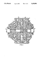
- FIG. 4 is a plan view of a cam structure with the intermediate camming roller and race angularly displaced for better force distribution;
- FIG. 5 is a straightened radial inward view into the camming structure shown in FIG. 4.
- a traction roller transmission comprises a housing 10 consisting of a central part 13, a front part 11 disposed at one end of the central part 13 and a rear part 12 disposed at the opposite end of the central part 13.
- the housing parts 11, 12 and 13 are held together as by tension bolts 14.
- Coaxial input and output shafts 15 and 16 extend through the front and the rear parts 11 and 12 of the housing 10 and are rotatably supported by input and output shaft bearings 17 and 18 and by central support bearings 19 and 20, or alternatively, one shaft may extend into a central bore in the other shaft to be supported therein.
- the input shaft 15 carries an input traction disc 21 and the output shaft 16 carries an output traction disc 22 disposed opposite the input traction disc.
- the traction discs 21 and 22 have opposite toroidal surfaces 23 and 24 and are adapted to engage therebetween power rollers 25 and 26 for the transmission of motion from the input traction disc to the output traction disc.
- the power rollers 25 and 26 are supported by bearings 27 on a shaft 28 journalled in a roller support structure 29.
- the shaft 28 has eccentric bearing portions 30 and 40 to permit slight movement of the rollers in a direction normal to the shaft when necessary for firm engagement with the input and output traction discs.
- Axial support is provided for the power rollers 25 and 26 by axial thrust bearings and seal assemblies 31 preferably of the type as described in applicant's earlier U.S. Pat. No. 3,788,713 issued Jan. 29, 1974 or in U.S. Pat. No. 3,486,391.
- the output traction disc 22 is mounted on an axial output thrust member 32 supported on the output shaft 16 for rotation therewith.
- a hydrostatic axial thrust bearing and seal structure 34 is disposed between the axial thrust member 32 and the housing part 12 to provide axial support for the thrust member 32 and the output traction disc 22.
- the input traction disc 21 is mounted on an axial input thrust member 35 and is freely rotatable on the input shaft 15.
- the input thrust member 35 forms a load cam structure 37 for forcing the input traction disc 21 toward the output traction disc 22 and both discs into engagement with the power rollers when a torque is transmitted through the transmission.
- the input thrust member 35 has cam faces 41 with cam rollers 43 disposed between the disc 21 and the cam faces 41 to be wedged therebetween when a torque is applied to the input shaft.
- the rollers 43 are held in position by a cage 45.
- the thrust member 35 is mounted on the input shaft 15 for rotation therewith and axially supported by a hydrostatic axial thrust bearing 39 disposed between the thrust member 35 and the housing part 11.
- the hydrostatic axial thrust bearings 39 and 34 are preferably of the type described in the present inventor's earlier U.S. Pat. No. 3,788,713. Hydraulic fluid is supplied to the bearings through passages 36 as shown in FIG. 1 only for bearing 34.
- the transmission and operation of such a transmission is described in greater detail in applicant's U.S. Pat. No. 4,086,820.
- the present invention is mainly concerned with the cam structure 37 for such a transmission which as shown in FIG. 1 includes for each cam three cam rollers disposed axially adjacent one another. This cam structure is shown in detail in FIGS. 2 and 3.
- FIGS. 2 and 3 there are provided three sets of cam rollers 43 disposed on the cam face 41 of the thrust member 35, the highs and lows of the cam face 41 being indicated by broken lines 47 and 49, respectively.
- the cam rollers are shown to be cylindrical because applicant has experienced better results with cylindrical rollers although they are subjected to some spin during relative movement of the thrust member 35 and an opposite thrust member such as the input traction disc 21. They are also shown with the same diameter although rollers with different diameters may be used if the roller races on the traction disc 21 and/or the thrust member 35 are machined appropriately for the selected roller size. It is pointed out that the races for the radially inner rollers 43a have substantially greater slopes than those for the radially outer rollers as the respective cam heights are equal but the race lengths are much shorter for the radially inner rollers.
- rollers are shown for each cam there may be more rollers.
- rollers there may also be balls or cones arranged in concentric races.
- the cam heights and lows may be displaced for adjacent concentric races as it is shown for the arrangement of FIGS. 4 and 5 where the cam disc includes four heights and lows and the cam heights and lows of the intermediate race are aligned with the cam lows and heights of the adjacent inner and outer cam races 53 and 55 as shown in FIG. 5.
- Such an arrangement is somewhat more expensive to manufacture but it provides for much improved axial force distribution. Again more than three roller races may be used if this is considered necessary for even greater force distribution.
Abstract
Description
Claims (6)
Priority Applications (1)
| Application Number | Priority Date | Filing Date | Title |
|---|---|---|---|
| US07/817,057 US5138894A (en) | 1992-01-06 | 1992-01-06 | Axial loading cam arrangement in or for a traction roller transmission |
Applications Claiming Priority (1)
| Application Number | Priority Date | Filing Date | Title |
|---|---|---|---|
| US07/817,057 US5138894A (en) | 1992-01-06 | 1992-01-06 | Axial loading cam arrangement in or for a traction roller transmission |
Publications (1)
| Publication Number | Publication Date |
|---|---|
| US5138894A true US5138894A (en) | 1992-08-18 |
Family
ID=25222268
Family Applications (1)
| Application Number | Title | Priority Date | Filing Date |
|---|---|---|---|
| US07/817,057 Expired - Lifetime US5138894A (en) | 1992-01-06 | 1992-01-06 | Axial loading cam arrangement in or for a traction roller transmission |
Country Status (1)
| Country | Link |
|---|---|
| US (1) | US5138894A (en) |
Cited By (39)
| Publication number | Priority date | Publication date | Assignee | Title |
|---|---|---|---|---|
| EP0703387A1 (en) * | 1994-08-26 | 1996-03-27 | Nsk Ltd | Method for forming cam face on structure member of loading cam device for toroidal-type continuously variable transmission |
| WO2005008101A1 (en) * | 2003-07-11 | 2005-01-27 | Getrag Getriebe- Und Zahnradfabrik Hermann Hagenmeyer Gmbh & Cie Kg | Variator disc and variator for a toroidal gearbox |
| US20090260945A1 (en) * | 2008-04-15 | 2009-10-22 | Schaeffler Kg | Prestressing unit |
| US20130095977A1 (en) * | 2004-10-05 | 2013-04-18 | Fallbrook Intellectual Property Company Llc | Continuously variable transmission |
| US8776633B2 (en) | 2006-01-30 | 2014-07-15 | Fallbrook Intellectual Property Company Llc | System for manipulating a continuously variable transmission |
| US8818661B2 (en) | 2008-08-05 | 2014-08-26 | Fallbrook Intellectual Property Company Llc | Methods for control of transmission and prime mover |
| US8845485B2 (en) | 2011-04-04 | 2014-09-30 | Fallbrook Intellectual Property Company Llc | Auxiliary power unit having a continuously variable transmission |
| US8852050B2 (en) | 2008-08-26 | 2014-10-07 | Fallbrook Intellectual Property Company Llc | Continuously variable transmission |
| US8870711B2 (en) | 2008-10-14 | 2014-10-28 | Fallbrook Intellectual Property Company Llc | Continuously variable transmission |
| US8888643B2 (en) | 2010-11-10 | 2014-11-18 | Fallbrook Intellectual Property Company Llc | Continuously variable transmission |
| US8900085B2 (en) | 2007-07-05 | 2014-12-02 | Fallbrook Intellectual Property Company Llc | Continuously variable transmission |
| US8996263B2 (en) | 2007-11-16 | 2015-03-31 | Fallbrook Intellectual Property Company Llc | Controller for variable transmission |
| US9017207B2 (en) | 2006-06-26 | 2015-04-28 | Fallbrook Intellectual Property Company Llc | Continuously variable transmission |
| US9022889B2 (en) | 2005-10-28 | 2015-05-05 | Fallbrook Intellectual Property Company Llc | Electromotive drives |
| US9046158B2 (en) | 2003-02-28 | 2015-06-02 | Fallbrook Intellectual Property Company Llc | Continuously variable transmission |
| US9074674B2 (en) | 2008-06-23 | 2015-07-07 | Fallbrook Intellectual Property Company Llc | Continuously variable transmission |
| US9086145B2 (en) | 2006-11-08 | 2015-07-21 | Fallbrook Intellectual Property Company Llc | Clamping force generator |
| US9121464B2 (en) | 2005-12-09 | 2015-09-01 | Fallbrook Intellectual Property Company Llc | Continuously variable transmission |
| US9182018B2 (en) | 2008-02-29 | 2015-11-10 | Fallbrook Intellectual Property Company Llc | Continuously and/or infinitely variable transmissions and methods therefor |
| US9239099B2 (en) | 2007-02-16 | 2016-01-19 | Fallbrook Intellectual Property Company Llc | Infinitely variable transmissions, continuously variable transmissions, methods, assemblies, subassemblies, and components therefor |
| US9249880B2 (en) | 2007-12-21 | 2016-02-02 | Fallbrook Intellectual Property Company Llc | Automatic transmissions and methods therefor |
| US9273760B2 (en) | 2007-04-24 | 2016-03-01 | Fallbrook Intellectual Property Company Llc | Electric traction drives |
| US9279482B2 (en) | 2009-04-16 | 2016-03-08 | Fallbrook Intellectual Property Company Llc | Continuously variable transmission |
| US9328807B2 (en) | 2007-02-01 | 2016-05-03 | Fallbrook Intellectual Property Company Llc | Systems and methods for control of transmission and/or prime mover |
| US9341246B2 (en) | 2005-11-22 | 2016-05-17 | Fallbrook Intellectual Property Company Llc | Continuously variable transmission |
| US9360089B2 (en) | 2010-03-03 | 2016-06-07 | Fallbrook Intellectual Property Company Llc | Infinitely variable transmissions, continuously variable transmissions, methods, assemblies, subassemblies, and components therefor |
| US9371894B2 (en) | 2007-02-12 | 2016-06-21 | Fallbrook Intellectual Property Company Llc | Continuously variable transmissions and methods therefor |
| US9611921B2 (en) | 2012-01-23 | 2017-04-04 | Fallbrook Intellectual Property Company Llc | Infinitely variable transmissions, continuously variable transmissions, methods, assemblies, subassemblies, and components therefor |
| US9618100B2 (en) | 2008-05-07 | 2017-04-11 | Fallbrook Intellectual Property Company Llc | Assemblies and methods for clamping force generation |
| US9677650B2 (en) | 2013-04-19 | 2017-06-13 | Fallbrook Intellectual Property Company Llc | Continuously variable transmission |
| US9683638B2 (en) | 2005-12-30 | 2017-06-20 | Fallbrook Intellectual Property Company Llc | Continuously variable gear transmission |
| US9683640B2 (en) | 2008-06-06 | 2017-06-20 | Fallbrook Intellectual Property Company Llc | Infinitely variable transmissions, continuously variable transmissions, methods, assemblies, subassemblies, and components therefor |
| US9945456B2 (en) | 2007-06-11 | 2018-04-17 | Fallbrook Intellectual Property Company Llc | Continuously variable transmission |
| US10047861B2 (en) | 2016-01-15 | 2018-08-14 | Fallbrook Intellectual Property Company Llc | Systems and methods for controlling rollback in continuously variable transmissions |
| US10458526B2 (en) | 2016-03-18 | 2019-10-29 | Fallbrook Intellectual Property Company Llc | Continuously variable transmissions, systems and methods |
| US10495197B2 (en) * | 2017-02-07 | 2019-12-03 | Motive Power Industry Co., Ltd. | Continuously variable transmission ring driving mechanism |
| US11174922B2 (en) | 2019-02-26 | 2021-11-16 | Fallbrook Intellectual Property Company Llc | Reversible variable drives and systems and methods for control in forward and reverse directions |
| US11215268B2 (en) | 2018-11-06 | 2022-01-04 | Fallbrook Intellectual Property Company Llc | Continuously variable transmissions, synchronous shifting, twin countershafts and methods for control of same |
| US11667351B2 (en) | 2016-05-11 | 2023-06-06 | Fallbrook Intellectual Property Company Llc | Systems and methods for automatic configuration and automatic calibration of continuously variable transmissions and bicycles having continuously variable transmission |
Citations (8)
| Publication number | Priority date | Publication date | Assignee | Title |
|---|---|---|---|---|
| US2292066A (en) * | 1939-11-17 | 1942-08-04 | Richard T Erban | Friction transmission mechanism |
| US3087348A (en) * | 1961-03-08 | 1963-04-30 | Excelermatic | Variable speed-ratio toroidal transmission |
| US3184983A (en) * | 1963-10-30 | 1965-05-25 | Excelermatic | Toroidal transmission mechanism with torque loading cam means |
| US3486391A (en) * | 1968-09-19 | 1969-12-30 | Excelermatic | Toroidal type transmission |
| US3788713A (en) * | 1972-05-23 | 1974-01-29 | Excelermatic | Hydrostatic thrust bearing |
| US4086820A (en) * | 1976-06-25 | 1978-05-02 | Excelermatic, Inc. | Infinitely variable traction roller transmission |
| US4463620A (en) * | 1982-09-07 | 1984-08-07 | Excelermatic Inc. | Infinitely variable traction roller transmission |
| US5027668A (en) * | 1989-03-31 | 1991-07-02 | Nissan Motor Co., Ltd. | Loading cam mechanism for toroidal type continuously variable transmission |
-
1992
- 1992-01-06 US US07/817,057 patent/US5138894A/en not_active Expired - Lifetime
Patent Citations (8)
| Publication number | Priority date | Publication date | Assignee | Title |
|---|---|---|---|---|
| US2292066A (en) * | 1939-11-17 | 1942-08-04 | Richard T Erban | Friction transmission mechanism |
| US3087348A (en) * | 1961-03-08 | 1963-04-30 | Excelermatic | Variable speed-ratio toroidal transmission |
| US3184983A (en) * | 1963-10-30 | 1965-05-25 | Excelermatic | Toroidal transmission mechanism with torque loading cam means |
| US3486391A (en) * | 1968-09-19 | 1969-12-30 | Excelermatic | Toroidal type transmission |
| US3788713A (en) * | 1972-05-23 | 1974-01-29 | Excelermatic | Hydrostatic thrust bearing |
| US4086820A (en) * | 1976-06-25 | 1978-05-02 | Excelermatic, Inc. | Infinitely variable traction roller transmission |
| US4463620A (en) * | 1982-09-07 | 1984-08-07 | Excelermatic Inc. | Infinitely variable traction roller transmission |
| US5027668A (en) * | 1989-03-31 | 1991-07-02 | Nissan Motor Co., Ltd. | Loading cam mechanism for toroidal type continuously variable transmission |
Cited By (88)
| Publication number | Priority date | Publication date | Assignee | Title |
|---|---|---|---|---|
| US5669274A (en) * | 1994-08-26 | 1997-09-23 | Nsk Ltd. | Method for forming cam face on structure member of loading cam device for toroidal-type continuously variable transmission |
| EP0703387A1 (en) * | 1994-08-26 | 1996-03-27 | Nsk Ltd | Method for forming cam face on structure member of loading cam device for toroidal-type continuously variable transmission |
| US9732848B2 (en) | 2003-02-28 | 2017-08-15 | Fallbrook Intellectual Property Company Llc | Continuously variable transmission |
| US9046158B2 (en) | 2003-02-28 | 2015-06-02 | Fallbrook Intellectual Property Company Llc | Continuously variable transmission |
| US10428939B2 (en) | 2003-02-28 | 2019-10-01 | Fallbrook Intellectual Property Company Llc | Continuously variable transmission |
| US7285070B2 (en) | 2003-07-11 | 2007-10-23 | Getrag Getriebe- Und Zahnradfabrik Hermann Hagenmeyer Gmbh & Cie Kg | Variator disk and variator for a toroidal transmission |
| US20060194669A1 (en) * | 2003-07-11 | 2006-08-31 | Guenter Ruehle | Variator disk and variator for a toroidal transmission |
| WO2005008101A1 (en) * | 2003-07-11 | 2005-01-27 | Getrag Getriebe- Und Zahnradfabrik Hermann Hagenmeyer Gmbh & Cie Kg | Variator disc and variator for a toroidal gearbox |
| US20130095977A1 (en) * | 2004-10-05 | 2013-04-18 | Fallbrook Intellectual Property Company Llc | Continuously variable transmission |
| US8920285B2 (en) * | 2004-10-05 | 2014-12-30 | Fallbrook Intellectual Property Company Llc | Continuously variable transmission |
| US10036453B2 (en) | 2004-10-05 | 2018-07-31 | Fallbrook Intellectual Property Company Llc | Continuously variable transmission |
| US9506562B2 (en) | 2005-10-28 | 2016-11-29 | Fallbrook Intellectual Property Company Llc | Electromotive drives |
| US9022889B2 (en) | 2005-10-28 | 2015-05-05 | Fallbrook Intellectual Property Company Llc | Electromotive drives |
| US9950608B2 (en) | 2005-10-28 | 2018-04-24 | Fallbrook Intellectual Property Company Llc | Electromotive drives |
| US9341246B2 (en) | 2005-11-22 | 2016-05-17 | Fallbrook Intellectual Property Company Llc | Continuously variable transmission |
| US9709138B2 (en) | 2005-11-22 | 2017-07-18 | Fallbrook Intellectual Property Company Llc | Continuously variable transmission |
| US10711869B2 (en) | 2005-11-22 | 2020-07-14 | Fallbrook Intellectual Property Company Llc | Continuously variable transmission |
| US11454303B2 (en) | 2005-12-09 | 2022-09-27 | Fallbrook Intellectual Property Company Llc | Continuously variable transmission |
| US9121464B2 (en) | 2005-12-09 | 2015-09-01 | Fallbrook Intellectual Property Company Llc | Continuously variable transmission |
| US10208840B2 (en) | 2005-12-09 | 2019-02-19 | Fallbrook Intellectual Property Company Llc | Continuously variable transmission |
| US9683638B2 (en) | 2005-12-30 | 2017-06-20 | Fallbrook Intellectual Property Company Llc | Continuously variable gear transmission |
| US11598397B2 (en) | 2005-12-30 | 2023-03-07 | Fallbrook Intellectual Property Company Llc | Continuously variable gear transmission |
| US8776633B2 (en) | 2006-01-30 | 2014-07-15 | Fallbrook Intellectual Property Company Llc | System for manipulating a continuously variable transmission |
| US9726282B2 (en) | 2006-06-26 | 2017-08-08 | Fallbrook Intellectual Property Company Llc | Continuously variable transmission |
| US9017207B2 (en) | 2006-06-26 | 2015-04-28 | Fallbrook Intellectual Property Company Llc | Continuously variable transmission |
| US9086145B2 (en) | 2006-11-08 | 2015-07-21 | Fallbrook Intellectual Property Company Llc | Clamping force generator |
| US9878719B2 (en) | 2007-02-01 | 2018-01-30 | Fallbrook Intellectual Property Company Llc | Systems and methods for control of transmission and/or prime mover |
| US10703372B2 (en) | 2007-02-01 | 2020-07-07 | Fallbrook Intellectual Property Company Llc | Systems and methods for control of transmission and/or prime mover |
| US9328807B2 (en) | 2007-02-01 | 2016-05-03 | Fallbrook Intellectual Property Company Llc | Systems and methods for control of transmission and/or prime mover |
| US9676391B2 (en) | 2007-02-01 | 2017-06-13 | Fallbrook Intellectual Property Company Llc | Systems and methods for control of transmission and/or prime mover |
| US10260607B2 (en) | 2007-02-12 | 2019-04-16 | Fallbrook Intellectual Property Company Llc | Continuously variable transmissions and methods therefor |
| US9371894B2 (en) | 2007-02-12 | 2016-06-21 | Fallbrook Intellectual Property Company Llc | Continuously variable transmissions and methods therefor |
| US9239099B2 (en) | 2007-02-16 | 2016-01-19 | Fallbrook Intellectual Property Company Llc | Infinitely variable transmissions, continuously variable transmissions, methods, assemblies, subassemblies, and components therefor |
| US10094453B2 (en) | 2007-02-16 | 2018-10-09 | Fallbrook Intellectual Property Company Llc | Infinitely variable transmissions, continuously variable transmissions, methods, assemblies, subassemblies, and components therefor |
| US10056811B2 (en) | 2007-04-24 | 2018-08-21 | Fallbrook Intellectual Property Company Llc | Electric traction drives |
| US9574643B2 (en) | 2007-04-24 | 2017-02-21 | Fallbrook Intellectual Property Company Llc | Electric traction drives |
| US9273760B2 (en) | 2007-04-24 | 2016-03-01 | Fallbrook Intellectual Property Company Llc | Electric traction drives |
| US9945456B2 (en) | 2007-06-11 | 2018-04-17 | Fallbrook Intellectual Property Company Llc | Continuously variable transmission |
| US8900085B2 (en) | 2007-07-05 | 2014-12-02 | Fallbrook Intellectual Property Company Llc | Continuously variable transmission |
| US9869388B2 (en) | 2007-07-05 | 2018-01-16 | Fallbrook Intellectual Property Company Llc | Continuously variable transmission |
| US10260629B2 (en) | 2007-07-05 | 2019-04-16 | Fallbrook Intellectual Property Company Llc | Continuously variable transmission |
| US10100927B2 (en) | 2007-11-16 | 2018-10-16 | Fallbrook Intellectual Property Company Llc | Controller for variable transmission |
| US11125329B2 (en) | 2007-11-16 | 2021-09-21 | Fallbrook Intellectual Property Company Llc | Controller for variable transmission |
| US8996263B2 (en) | 2007-11-16 | 2015-03-31 | Fallbrook Intellectual Property Company Llc | Controller for variable transmission |
| US9249880B2 (en) | 2007-12-21 | 2016-02-02 | Fallbrook Intellectual Property Company Llc | Automatic transmissions and methods therefor |
| US9739375B2 (en) | 2007-12-21 | 2017-08-22 | Fallbrook Intellectual Property Company Llc | Automatic transmissions and methods therefor |
| US10704687B2 (en) | 2007-12-21 | 2020-07-07 | Fallbrook Intellectual Property Company Llc | Automatic transmissions and methods therefor |
| US9850993B2 (en) | 2008-02-29 | 2017-12-26 | Fallbrook Intellectual Property Company Llc | Continuously and/or infinitely variable transmissions and methods therefor |
| US9182018B2 (en) | 2008-02-29 | 2015-11-10 | Fallbrook Intellectual Property Company Llc | Continuously and/or infinitely variable transmissions and methods therefor |
| US20090260945A1 (en) * | 2008-04-15 | 2009-10-22 | Schaeffler Kg | Prestressing unit |
| US9618100B2 (en) | 2008-05-07 | 2017-04-11 | Fallbrook Intellectual Property Company Llc | Assemblies and methods for clamping force generation |
| US9683640B2 (en) | 2008-06-06 | 2017-06-20 | Fallbrook Intellectual Property Company Llc | Infinitely variable transmissions, continuously variable transmissions, methods, assemblies, subassemblies, and components therefor |
| US10634224B2 (en) | 2008-06-06 | 2020-04-28 | Fallbrook Intellectual Property Company Llc | Infinitely variable transmissions, continuously variable transmissions, methods, assemblies, subassemblies, and components therefor |
| US10066713B2 (en) | 2008-06-23 | 2018-09-04 | Fallbrook Intellectual Property Company Llc | Continuously variable transmission |
| US9528561B2 (en) | 2008-06-23 | 2016-12-27 | Fallbrook Intellectual Property Company Llc | Continuously variable transmission |
| US9074674B2 (en) | 2008-06-23 | 2015-07-07 | Fallbrook Intellectual Property Company Llc | Continuously variable transmission |
| US9365203B2 (en) | 2008-08-05 | 2016-06-14 | Fallbrook Intellectual Property Company Llc | Systems and methods for control of transmission and/or prime mover |
| US8818661B2 (en) | 2008-08-05 | 2014-08-26 | Fallbrook Intellectual Property Company Llc | Methods for control of transmission and prime mover |
| US9878717B2 (en) | 2008-08-05 | 2018-01-30 | Fallbrook Intellectual Property Company Llc | Systems and methods for control of transmission and/or prime mover |
| US9903450B2 (en) | 2008-08-26 | 2018-02-27 | Fallbrook Intellectual Property Company Llc | Continuously variable transmission |
| US8852050B2 (en) | 2008-08-26 | 2014-10-07 | Fallbrook Intellectual Property Company Llc | Continuously variable transmission |
| US10704657B2 (en) | 2008-08-26 | 2020-07-07 | Fallbrook Intellectual Property Company Llc | Continuously variable transmission |
| US10253880B2 (en) | 2008-10-14 | 2019-04-09 | Fallbrook Intellectual Property Company Llc | Continuously variable transmission |
| US9574642B2 (en) | 2008-10-14 | 2017-02-21 | Fallbrook Intellectual Property Company Llc | Continuously variable transmission |
| US8870711B2 (en) | 2008-10-14 | 2014-10-28 | Fallbrook Intellectual Property Company Llc | Continuously variable transmission |
| US10746270B2 (en) | 2009-04-16 | 2020-08-18 | Fallbrook Intellectual Property Company Llc | Continuously variable transmission |
| US9279482B2 (en) | 2009-04-16 | 2016-03-08 | Fallbrook Intellectual Property Company Llc | Continuously variable transmission |
| US9920823B2 (en) | 2009-04-16 | 2018-03-20 | Fallbrook Intellectual Property Company Llc | Continuously variable transmission |
| US9360089B2 (en) | 2010-03-03 | 2016-06-07 | Fallbrook Intellectual Property Company Llc | Infinitely variable transmissions, continuously variable transmissions, methods, assemblies, subassemblies, and components therefor |
| US10066712B2 (en) | 2010-03-03 | 2018-09-04 | Fallbrook Intellectual Property Company Llc | Infinitely variable transmissions, continuously variable transmissions, methods, assemblies, subassemblies, and components therefor |
| US8888643B2 (en) | 2010-11-10 | 2014-11-18 | Fallbrook Intellectual Property Company Llc | Continuously variable transmission |
| US9291251B2 (en) | 2010-11-10 | 2016-03-22 | Fallbrook Intellectual Property Company Llc | Continuously variable transmission |
| US10197147B2 (en) | 2010-11-10 | 2019-02-05 | Fallbrook Intellectual Property Company Llc | Continuously variable transmission |
| US8845485B2 (en) | 2011-04-04 | 2014-09-30 | Fallbrook Intellectual Property Company Llc | Auxiliary power unit having a continuously variable transmission |
| US10428915B2 (en) | 2012-01-23 | 2019-10-01 | Fallbrook Intellectual Property Company Llc | Infinitely variable transmissions, continuously variable transmissions, methods, assemblies, subassemblies, and components therefor |
| US9611921B2 (en) | 2012-01-23 | 2017-04-04 | Fallbrook Intellectual Property Company Llc | Infinitely variable transmissions, continuously variable transmissions, methods, assemblies, subassemblies, and components therefor |
| US10323732B2 (en) | 2013-04-19 | 2019-06-18 | Fallbrook Intellectual Property Company Llc | Continuously variable transmission |
| US9677650B2 (en) | 2013-04-19 | 2017-06-13 | Fallbrook Intellectual Property Company Llc | Continuously variable transmission |
| US10920882B2 (en) | 2016-01-15 | 2021-02-16 | Fallbrook Intellectual Property Company Llc | Systems and methods for controlling rollback in continuously variable transmissions |
| US11306818B2 (en) | 2016-01-15 | 2022-04-19 | Fallbrook Intellectual Property Company Llc | Systems and methods for controlling rollback in continuously variable transmissions |
| US10047861B2 (en) | 2016-01-15 | 2018-08-14 | Fallbrook Intellectual Property Company Llc | Systems and methods for controlling rollback in continuously variable transmissions |
| US10458526B2 (en) | 2016-03-18 | 2019-10-29 | Fallbrook Intellectual Property Company Llc | Continuously variable transmissions, systems and methods |
| US11667351B2 (en) | 2016-05-11 | 2023-06-06 | Fallbrook Intellectual Property Company Llc | Systems and methods for automatic configuration and automatic calibration of continuously variable transmissions and bicycles having continuously variable transmission |
| US10495197B2 (en) * | 2017-02-07 | 2019-12-03 | Motive Power Industry Co., Ltd. | Continuously variable transmission ring driving mechanism |
| US11215268B2 (en) | 2018-11-06 | 2022-01-04 | Fallbrook Intellectual Property Company Llc | Continuously variable transmissions, synchronous shifting, twin countershafts and methods for control of same |
| US11624432B2 (en) | 2018-11-06 | 2023-04-11 | Fallbrook Intellectual Property Company Llc | Continuously variable transmissions, synchronous shifting, twin countershafts and methods for control of same |
| US11174922B2 (en) | 2019-02-26 | 2021-11-16 | Fallbrook Intellectual Property Company Llc | Reversible variable drives and systems and methods for control in forward and reverse directions |
| US11530739B2 (en) | 2019-02-26 | 2022-12-20 | Fallbrook Intellectual Property Company Llc | Reversible variable drives and systems and methods for control in forward and reverse directions |
Similar Documents
| Publication | Publication Date | Title |
|---|---|---|
| US5138894A (en) | Axial loading cam arrangement in or for a traction roller transmission | |
| US6004239A (en) | Friction type continuously variable speed changing mechanism | |
| US5385514A (en) | High ratio planetary transmission | |
| US4846008A (en) | Traction roller transmission | |
| US4398778A (en) | Ball bearing | |
| US3375739A (en) | Conical planetary friction gear drive | |
| US6318516B1 (en) | Bearing arrangement for actuating a brake in a brake system | |
| US6102489A (en) | Wheel support arrangement for a vehicle drive axle | |
| US3871239A (en) | Variable speed drive | |
| US5536091A (en) | Thrust ball bearing for use with power rollers | |
| US4224840A (en) | Traction roller transmission | |
| US5025671A (en) | High ratio planetary type traction roller transmission | |
| EP1210532B1 (en) | Gearing for power sharing in planetary transmission | |
| US4923313A (en) | Device in rolling bearings | |
| US3941004A (en) | Traction roller transmission | |
| US20050058381A1 (en) | Roller bearing | |
| US6158897A (en) | Gear with bearing arrangement | |
| EP0815368B2 (en) | Planet gear for high revolutions | |
| US3700845A (en) | Wire race ball bearing | |
| US5984827A (en) | Toroidal type continuously variable transmission | |
| US4463620A (en) | Infinitely variable traction roller transmission | |
| KR20000047367A (en) | Friction resistance generator | |
| US6179744B1 (en) | Trunnion supporting structure of a toroidal continuously variable transmission | |
| US4235128A (en) | Planetary gear provided with friction planet wheels | |
| US5547432A (en) | Toroidal-type continuously variable transmission |
Legal Events
| Date | Code | Title | Description |
|---|---|---|---|
| AS | Assignment |
Owner name: EXCELERMATIC INC. A COMPANY OF DE Free format text: ASSIGNMENT OF ASSIGNORS INTEREST.;ASSIGNOR:KRAUS, CHARLES E.;REEL/FRAME:005980/0814 Effective date: 19911217 Owner name: EXCELERMATIC INC., STATELESS Free format text: ASSIGNMENT OF ASSIGNORS INTEREST;ASSIGNOR:KRAUS, CHARLES E.;REEL/FRAME:005980/0814 Effective date: 19911217 |
|
| STCF | Information on status: patent grant |
Free format text: PATENTED CASE |
|
| FPAY | Fee payment |
Year of fee payment: 4 |
|
| FEPP | Fee payment procedure |
Free format text: PAT HLDR NO LONGER CLAIMS SMALL ENT STAT AS INDIV INVENTOR (ORIGINAL EVENT CODE: LSM1); ENTITY STATUS OF PATENT OWNER: LARGE ENTITY |
|
| REMI | Maintenance fee reminder mailed | ||
| FPAY | Fee payment |
Year of fee payment: 8 |
|
| SULP | Surcharge for late payment | ||
| REMI | Maintenance fee reminder mailed | ||
| FPAY | Fee payment |
Year of fee payment: 12 |
|
| SULP | Surcharge for late payment |
Year of fee payment: 11 |