US5132842A - Optical image transformation system - Google Patents
Optical image transformation system Download PDFInfo
- Publication number
- US5132842A US5132842A US07/383,954 US38395489A US5132842A US 5132842 A US5132842 A US 5132842A US 38395489 A US38395489 A US 38395489A US 5132842 A US5132842 A US 5132842A
- Authority
- US
- United States
- Prior art keywords
- pulse
- modified
- optical image
- throughput
- optical
- Prior art date
- Legal status (The legal status is an assumption and is not a legal conclusion. Google has not performed a legal analysis and makes no representation as to the accuracy of the status listed.)
- Expired - Lifetime
Links
Images

Classifications
-
- G—PHYSICS
- G06—COMPUTING; CALCULATING OR COUNTING
- G06V—IMAGE OR VIDEO RECOGNITION OR UNDERSTANDING
- G06V10/00—Arrangements for image or video recognition or understanding
- G06V10/88—Image or video recognition using optical means, e.g. reference filters, holographic masks, frequency domain filters or spatial domain filters
Definitions
- the present invention relates to optical pattern recognition systems and, in particular, to an optical ring resonator that transforms an input image into a series of similar images having various sizes and orientations.
- optical pattern recognition systems generally require proper alignment of an input image with respect to a stored reference. Variations in orientation or size of the input image when compared to the on-board reference can lead to non-recognition of the image. Therefore, the adaptability of a system to variations in an input scene is a factor that can determine whether or not the pattern recognition process is successful. In dynamic or uncertain environments, correlation of input images that deviate in orientation or scale from a given reference continues to be a problem in pattern recognition systems.
- the present invention comprises an optical device that transforms input images for correlation with reference images by an optical pattern recognition system. Instead of using a large library of stored images of various sizes and orientations as in the prior art, the present invention performs multiple transformations on an input image and compares the rotated and/or scaled versions of the input image with a single version of each reference image to be recognized.
- a pulsed laser beam that carries an input image is directed into a ring resonator.
- the input pulse is split by a beam splitter to produce an output pulse and a throughput pulse.
- the throughput pulse is transformed by the ring resonator into a modified pulse that is a version of the input pulse transformed by a predetermined factor in orientation or scale, for example.
- the modified pulse is directed to the beam splitter to generate a modified output pulse and a modified throught pulse. This process is self-repeating to produce a series of successively modified output pulses equally spaced in time.
- the output pulses are separated by the travel time of the light through the ring resonator.
- the input optical pulse is shorter than the length of the ring resonator so the output images do not overlap.
- the series of successively modified images output by the present invention can be correlated with a given reference image in an image recognition system. Because the output images exit the resonator at known intervals, the amount of modification of the input image can be determined by noting the time at which a correlation peak occurs.
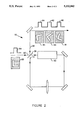
- FIG. 1 is a schematic drawing of an optical ring resonator of the present invention for transforming the scale of an input image
- FIG. 2 is a schematic drawing of an optical ring resonator of the present invention for transforming the orientation of an input image.
- the correlation of an input image with a reference image is sensitive to factors such as the scale and orientation of the input image with respect to the reference.
- the present invention uses an optical ring resonator to generate a series of successively modified input images to be compared with the reference.
- FIG. 1 One embodiment of the present invention is illustrated in FIG. 1 and identified as ring resonator 10.
- a pulsed laser beam 12 is input to ring resonator 10.
- Each pulse 14 of laser beam 12 carries an optical image 15.
- Input pulse 14 of laser beam 12 is directed onto a beam splitter 16 that splits input pulse 14 into an output pulse 18 and a throughput pulse 20.
- Pulse 20 is directed through an optical system, such as a demagnifying lens system 22, that modifies the scale of input image 15.
- Lens system 22 transforms pulse 20 into a modified pulse 32, which is directed by mirrors 24, 26, and 28 through an imaging lens 30 and onto beam splitter 16.
- Beam splitter 16 splits modified pulse 32 into a modified output pulse, identified as pulse 40, and a modified throughput pulse redirected through demagnifying lens system 22.
- Output pulses 40, 42, and 44 are spaced by the travel time of pulse 20 through ring resonator 10.
- the length of input pulse 14 is less than the length of ring resonator 10 so that the output pulses do not overlap.
- Output pulses 40, 42, and 44 carry successively modified versions of input image 15, illustrated as images 41, 43, and 45, respectively.
- Output images 41, 43, and 45 are successively reduced versions of input image 15, each output image being reduced from the preceding image by a factor determined by demagnifying system 22.
- ring resonator 10 outputs a series of transformations of input image 15, with each output image modified from the preceding image by a predetermined factor.
- the output pulses are all spaced in time by a known constant determined by the travel time of light through resonator 10.
- FIG. 2 Another embodiment of the present invention is illustrated in FIG. 2 and identified as ring resonator 50.
- Resonator 50 is identical to resonator 10 except that demagnifying system 22 is replaced by an image rotation system 62.
- a pulsed laser beam 52 has an input pulse 54 that carries an input image 55.
- Input pulse 54 is split by a beam splitter 56 into an output pulse 58 and a throughput pulse 60.
- Throughput pulse 60 is directed through an image rotation system 62 that changes the orientation of input image 55 by a predetermined angle of rotation.
- Image rotation system 62 may comprise, for example, a pair of dove prisms that rotate the input image by a given incremental angle.
- the rotated image is carried by pulse 72 to beam splitter 56 that provides a modified output pulse 80 and a modified throughput pulse for further image rotation.
- resonator 50 generates a series of output pulses, such as pulses 80, 82, and 84, that carry successively rotated images, such as images 81, 83, and 85, respectively.
- lens system 22 of resonator 10 may comprise a magnifying system to generate a series of enlarged versions of input image 15.
- the functions of resonators 10 and 50 may be combined in various ways to generate a matrix of output images successively modified in scale and orientation.
- the input image may be successively modified by other factors such as intensity or aspect angle.
- the transformed images can be directed into an optical Fourier system for correlation with stored reference image. Because the present invention generates a series of successively modified versions of the input image, only one version of each reference image must be stored by the image recognition system.
- One general scheme of invariant pattern recognition involves the use of the autocorrelation function as the feature of interest of an image. Rotation and scale information are preserved by this method because the autocorrelation function rotates and changes scale with the original image. The method is to first extract the autocorrelation function and then to extract rotation and scale invariant features from the autocorrelation.
- circular harmonic expansions can be used so that the final step involves the matching of circular harmonic coefficient functions.
- the operations involving the computation of autocorrelation functions and the matching of images can be achieved using optical means.
- the system can be dynamically updated through the use of photorefractive crystals.
Abstract
An optical system is provided for the transformation of input images to be correlated by a pattern recognition system. A pulse of light from a laser carries an input image to a beam splitter. The beam splitter divides the input pulse into an output pulse and a thoughput pulse that is directed through an optical ring resonator. The ring resonator is an optical reimaging system that transforms the input image in scale or orientation. The transformed version of the input image is then directed to the beam splitter where it is split into a modified output pulse and a modified throughput pulse that reenters the ring resonator. The transformation process is self-repeating to generate a series of successively modified output images that are equally spaced in time. The series of output images can be provided to an optical pattern recognition system for correlation with a stored reference. The generation of successive transformations of the input image precludes the necessity of storing a large library of reference images to be matched with the input image.
Description
The present invention relates to optical pattern recognition systems and, in particular, to an optical ring resonator that transforms an input image into a series of similar images having various sizes and orientations.
In the field of optical pattern recognition, there is a need for simple and reliable devices that recognize specified optical patterns. Such devices are useful, for example, in industrial robots for distinguishing different physical objects, in photo-interpretation for automatically scanning for specific images, and in missile guidance systems for real-time target acquisition. In military and space applications, real-time image recognition is often needed in environments where a human observer cannot be present. In such remote environments, it is usually desirable that an image recognition system be small, light weight, and reliable.
For effective operation, optical pattern recognition systems generally require proper alignment of an input image with respect to a stored reference. Variations in orientation or size of the input image when compared to the on-board reference can lead to non-recognition of the image. Therefore, the adaptability of a system to variations in an input scene is a factor that can determine whether or not the pattern recognition process is successful. In dynamic or uncertain environments, correlation of input images that deviate in orientation or scale from a given reference continues to be a problem in pattern recognition systems.
Prior methods of pattern recognition designed to be invariant with transformations such as size and rotation have met with limited success. These prior methods range from the systematic extraction of pattern features to the common but inefficient technique of storing multiple rotated and scaled versions of the patterns to be recognized. The latter technique is useful in some situations, but it requires the storage of a vast quantity of necessarily redundant data. Thus, a need remains for an optical pattern recognition system that can perform reliable image correlations without the prior storage of a large library of redundant images.
The present invention comprises an optical device that transforms input images for correlation with reference images by an optical pattern recognition system. Instead of using a large library of stored images of various sizes and orientations as in the prior art, the present invention performs multiple transformations on an input image and compares the rotated and/or scaled versions of the input image with a single version of each reference image to be recognized.
In the present invention, a pulsed laser beam that carries an input image is directed into a ring resonator. The input pulse is split by a beam splitter to produce an output pulse and a throughput pulse. The throughput pulse is transformed by the ring resonator into a modified pulse that is a version of the input pulse transformed by a predetermined factor in orientation or scale, for example. The modified pulse is directed to the beam splitter to generate a modified output pulse and a modified throught pulse. This process is self-repeating to produce a series of successively modified output pulses equally spaced in time. The output pulses are separated by the travel time of the light through the ring resonator. The input optical pulse is shorter than the length of the ring resonator so the output images do not overlap.
The series of successively modified images output by the present invention can be correlated with a given reference image in an image recognition system. Because the output images exit the resonator at known intervals, the amount of modification of the input image can be determined by noting the time at which a correlation peak occurs.
For a more complete understanding of the present invention and for further advantages thereof, the following Description of the Preferred Embodiment makes reference to the accompanying Drawings, in which:
FIG. 1 is a schematic drawing of an optical ring resonator of the present invention for transforming the scale of an input image; and
FIG. 2 is a schematic drawing of an optical ring resonator of the present invention for transforming the orientation of an input image.
In optical pattern recognition systems, the correlation of an input image with a reference image is sensitive to factors such as the scale and orientation of the input image with respect to the reference. Instead of storing a library of references having variations in scale and orientation, the present invention uses an optical ring resonator to generate a series of successively modified input images to be compared with the reference. One embodiment of the present invention is illustrated in FIG. 1 and identified as ring resonator 10.
A pulsed laser beam 12 is input to ring resonator 10. Each pulse 14 of laser beam 12 carries an optical image 15. Input pulse 14 of laser beam 12 is directed onto a beam splitter 16 that splits input pulse 14 into an output pulse 18 and a throughput pulse 20. Pulse 20 is directed through an optical system, such as a demagnifying lens system 22, that modifies the scale of input image 15. Lens system 22 transforms pulse 20 into a modified pulse 32, which is directed by mirrors 24, 26, and 28 through an imaging lens 30 and onto beam splitter 16. Beam splitter 16 splits modified pulse 32 into a modified output pulse, identified as pulse 40, and a modified throughput pulse redirected through demagnifying lens system 22. This process repeats itself to generate successively modified output pulses, such as pulses 42 and 44. Output pulses 40, 42, and 44 are spaced by the travel time of pulse 20 through ring resonator 10. The length of input pulse 14 is less than the length of ring resonator 10 so that the output pulses do not overlap. Output pulses 40, 42, and 44 carry successively modified versions of input image 15, illustrated as images 41, 43, and 45, respectively. Output images 41, 43, and 45 are successively reduced versions of input image 15, each output image being reduced from the preceding image by a factor determined by demagnifying system 22. Thus, ring resonator 10 outputs a series of transformations of input image 15, with each output image modified from the preceding image by a predetermined factor. In addition, the output pulses are all spaced in time by a known constant determined by the travel time of light through resonator 10.
Another embodiment of the present invention is illustrated in FIG. 2 and identified as ring resonator 50. Resonator 50 is identical to resonator 10 except that demagnifying system 22 is replaced by an image rotation system 62. A pulsed laser beam 52 has an input pulse 54 that carries an input image 55. Input pulse 54 is split by a beam splitter 56 into an output pulse 58 and a throughput pulse 60. Throughput pulse 60 is directed through an image rotation system 62 that changes the orientation of input image 55 by a predetermined angle of rotation. Image rotation system 62 may comprise, for example, a pair of dove prisms that rotate the input image by a given incremental angle. The rotated image is carried by pulse 72 to beam splitter 56 that provides a modified output pulse 80 and a modified throughput pulse for further image rotation. As this process repeats itself, resonator 50 generates a series of output pulses, such as pulses 80, 82, and 84, that carry successively rotated images, such as images 81, 83, and 85, respectively.
The transformed images generated by the present invention are not limited to those described above in conjunction with resonators 10 and 50. For example, lens system 22 of resonator 10 may comprise a magnifying system to generate a series of enlarged versions of input image 15. Also, the functions of resonators 10 and 50 may be combined in various ways to generate a matrix of output images successively modified in scale and orientation. In addition, the input image may be successively modified by other factors such as intensity or aspect angle.
After an input image is transformed into a series of images of various scales and orientations by the present invention, the transformed images can be directed into an optical Fourier system for correlation with stored reference image. Because the present invention generates a series of successively modified versions of the input image, only one version of each reference image must be stored by the image recognition system. One general scheme of invariant pattern recognition involves the use of the autocorrelation function as the feature of interest of an image. Rotation and scale information are preserved by this method because the autocorrelation function rotates and changes scale with the original image. The method is to first extract the autocorrelation function and then to extract rotation and scale invariant features from the autocorrelation. For rotation invariance, for example, circular harmonic expansions can be used so that the final step involves the matching of circular harmonic coefficient functions. The operations involving the computation of autocorrelation functions and the matching of images can be achieved using optical means. Furthermore, the system can be dynamically updated through the use of photorefractive crystals.
Although the present invention has been described with respect to several embodiments thereof, various changes and modifications may be suggested to one skilled in the art. Therefore, it is intended that the present invention encompass such changes and modifications as fall within the scope of the appended claims.
Claims (9)
1. A method of generating successive transformations of an optical image, comprising the steps of:
receiving a laser beam input pulse carrying the optical image;
splitting said input pulse into an output pulse and a throughput pulse;
directing said throughput pulse through an optical ring resonator:
optically transforming said throughput pulse into a modified pulse carrying a transformation of the optical image;
splitting said modified pulse into a modified output pulse and a modified throughput pulse; and
directing said modified throughput pulse and successive modifications thereof through said optical ring resonator to generate successive modifications of said modified output and throughput pulses, said successive modifications comprising successive transformations of the optical image.
2. The method of claim 1, wherein the step of optically transforming comprises modifying the optical image by a predetermined factor in scale.
3. The method of claim 1, wherein the step of optically transforming comprises rotating the optical image by a predetermined angle of rotation.
4. The method of claim 1, wherein the step of optically transforming comprises modifying the optical image by at least one of the factors of scale, orientation, aspect ratio, and intensity.
5. A method of optical image recognition, comprising the steps of:
storing a single version of a reference image to be recognized;
receiving a laser beam input pulse carrying an optical image;
splitting said input pulse into an output pulse and a throughput pulse;
directing said throughput pulse through an optical ring resonator;
optically transforming said throughput pulse into a modified pulse carrying a transformation of said optical image;
splitting said modified pulse into a modified output pulse and a modified throughput pulse;
directing said modified throughput pulse and successive modifications thereof through said optical ring resonator to generate successive modifications of said modified output and throughput pulses, said successive modifications comprising successive transformations of said optical image;
comparing said successive transformations of said optical image with said reference image; and
generating a correlation peak when one of said transformations of said optical image matches said reference image.
6. The method of claim 5, wherein the step of optically transforming comprises modifying said optical image by a predetermined amount of at least one of the factors of scale, orientation, aspect ratio, and intensity.
7. The method of claim 5, further comprising the steps of:
providing said successive modifications of said optical image in a series of output pulses equally spaced in time; and
determining the amount of modification of the modified optical image that matches said reference image by noting the time at which said correlation peak occurs.
8. A method of optical image recognition, comprising the steps of:
storing a single version of each of a plurality of reference images to be recognized;
receiving a laser beam input pulse carrying an optical image;
splitting said input pulse into an output pulse and a throughput pulse;
directing said throughput pulse through an optical ring resonator;
optically transforming said throughput pulse into a modified pulse, said modified pulse comprising said optical image modified by a predetermined amount of at least one of the factors of scale, orientation, aspect ratio, and intensity;
splitting said modified pulse into a modified output pulse and a modified throughput pulse;
directing said modified throughput pulse and successive modifications thereof through said optical ring resonator to generate successive modifications of said modified output and throughput pulses, said successive modifications comprising successive modifications of said optical image;
comparing said successive modifications of said optical image with each of said reference images; and
generating a correlation peak when one of said modifications of said optical image matches one of said reference images.
9. The method of claim 8, further comprising the steps of:
providing said successive modifications of said optical image in a series of output pulses equally spaced in time; and
determining the amount of modification of the modified optical image that matches said one of said reference images by noting the time at which said correlation peak occurs.
Priority Applications (1)
| Application Number | Priority Date | Filing Date | Title |
|---|---|---|---|
| US07/383,954 US5132842A (en) | 1989-07-21 | 1989-07-21 | Optical image transformation system |
Applications Claiming Priority (1)
| Application Number | Priority Date | Filing Date | Title |
|---|---|---|---|
| US07/383,954 US5132842A (en) | 1989-07-21 | 1989-07-21 | Optical image transformation system |
Publications (1)
| Publication Number | Publication Date |
|---|---|
| US5132842A true US5132842A (en) | 1992-07-21 |
Family
ID=23515458
Family Applications (1)
| Application Number | Title | Priority Date | Filing Date |
|---|---|---|---|
| US07/383,954 Expired - Lifetime US5132842A (en) | 1989-07-21 | 1989-07-21 | Optical image transformation system |
Country Status (1)
| Country | Link |
|---|---|
| US (1) | US5132842A (en) |
Cited By (14)
| Publication number | Priority date | Publication date | Assignee | Title |
|---|---|---|---|---|
| US5581636A (en) * | 1992-05-26 | 1996-12-03 | United Parcel Service Of America, Inc. | Method and system for transformed target image acquisition |
| US5719969A (en) * | 1992-06-30 | 1998-02-17 | Canon Kabushiki Kaisha | Data input apparatus and data processing apparatus |
| US20050271300A1 (en) * | 2004-06-02 | 2005-12-08 | Pina Robert K | Image registration system and method |
| US6975755B1 (en) * | 1999-11-25 | 2005-12-13 | Canon Kabushiki Kaisha | Image processing method and apparatus |
| US20080152082A1 (en) * | 2006-08-16 | 2008-06-26 | Michel Bouchard | Method and apparatus for use in security screening providing incremental display of threat detection information and security system incorporating same |
| US7606444B1 (en) * | 2002-11-29 | 2009-10-20 | Ricoh Company, Ltd. | Multimodal access of meeting recordings |
| WO2009145931A1 (en) * | 2008-05-27 | 2009-12-03 | Nikon Corporation | Device and method for estimating defocus blur size in an image |
| US7734102B2 (en) | 2005-05-11 | 2010-06-08 | Optosecurity Inc. | Method and system for screening cargo containers |
| US7899232B2 (en) | 2006-05-11 | 2011-03-01 | Optosecurity Inc. | Method and apparatus for providing threat image projection (TIP) in a luggage screening system, and luggage screening system implementing same |
| US7991242B2 (en) | 2005-05-11 | 2011-08-02 | Optosecurity Inc. | Apparatus, method and system for screening receptacles and persons, having image distortion correction functionality |
| US8494210B2 (en) | 2007-03-30 | 2013-07-23 | Optosecurity Inc. | User interface for use in security screening providing image enhancement capabilities and apparatus for implementing same |
| US9632206B2 (en) | 2011-09-07 | 2017-04-25 | Rapiscan Systems, Inc. | X-ray inspection system that integrates manifest data with imaging/detection processing |
| US9953137B2 (en) | 2012-07-06 | 2018-04-24 | Nant Holdings Ip, Llc | Healthcare analysis stream management |
| US10302807B2 (en) | 2016-02-22 | 2019-05-28 | Rapiscan Systems, Inc. | Systems and methods for detecting threats and contraband in cargo |
Citations (12)
| Publication number | Priority date | Publication date | Assignee | Title |
|---|---|---|---|---|
| US4011523A (en) * | 1975-10-21 | 1977-03-08 | Trw Inc. | Azimuthal mode control for laser |
| US4277137A (en) * | 1978-10-06 | 1981-07-07 | The United States Of America As Represented By The Secretary Of The Army | Coherent optical correlator |
| US4414684A (en) * | 1979-12-24 | 1983-11-08 | Interlock Sicherheitssysteme Gmbh | Method and apparatus for performing a comparison of given patterns, in particular fingerprints |
| US4426663A (en) * | 1982-01-06 | 1984-01-17 | The United States Of America As Represented By The Secretary Of The Air Force | Real-time optical filtering method with improved filtered image detection and bandwidth adjustment |
| US4429393A (en) * | 1981-06-12 | 1984-01-31 | Hughes Aircraft Company | Double phase-conjugate ring resonator |
| US4618991A (en) * | 1983-05-23 | 1986-10-21 | Hitachi, Ltd. | Processing method for the rotation of an image |
| US4637056A (en) * | 1983-10-13 | 1987-01-13 | Battelle Development Corporation | Optical correlator using electronic image preprocessing |
| US4651297A (en) * | 1984-11-28 | 1987-03-17 | General Dynamics, Pomona Division | Two-dimensional image correlator |
| US4655588A (en) * | 1985-02-25 | 1987-04-07 | The United States Of America As Represented By The Secretary Of The Army | Injection controlled laser transmitter with twin local oscillators |
| US4695973A (en) * | 1985-10-22 | 1987-09-22 | The United States Of America As Represented By The Secretary Of The Air Force | Real-time programmable optical correlator |
| US4731788A (en) * | 1986-05-27 | 1988-03-15 | El-Op Electro-Optics Industries Limited | Low divergence laser apparatus |
| US4799780A (en) * | 1987-01-23 | 1989-01-24 | The Aerospace Corporation | Aberrated suppressor mirror |
-
1989
- 1989-07-21 US US07/383,954 patent/US5132842A/en not_active Expired - Lifetime
Patent Citations (12)
| Publication number | Priority date | Publication date | Assignee | Title |
|---|---|---|---|---|
| US4011523A (en) * | 1975-10-21 | 1977-03-08 | Trw Inc. | Azimuthal mode control for laser |
| US4277137A (en) * | 1978-10-06 | 1981-07-07 | The United States Of America As Represented By The Secretary Of The Army | Coherent optical correlator |
| US4414684A (en) * | 1979-12-24 | 1983-11-08 | Interlock Sicherheitssysteme Gmbh | Method and apparatus for performing a comparison of given patterns, in particular fingerprints |
| US4429393A (en) * | 1981-06-12 | 1984-01-31 | Hughes Aircraft Company | Double phase-conjugate ring resonator |
| US4426663A (en) * | 1982-01-06 | 1984-01-17 | The United States Of America As Represented By The Secretary Of The Air Force | Real-time optical filtering method with improved filtered image detection and bandwidth adjustment |
| US4618991A (en) * | 1983-05-23 | 1986-10-21 | Hitachi, Ltd. | Processing method for the rotation of an image |
| US4637056A (en) * | 1983-10-13 | 1987-01-13 | Battelle Development Corporation | Optical correlator using electronic image preprocessing |
| US4651297A (en) * | 1984-11-28 | 1987-03-17 | General Dynamics, Pomona Division | Two-dimensional image correlator |
| US4655588A (en) * | 1985-02-25 | 1987-04-07 | The United States Of America As Represented By The Secretary Of The Army | Injection controlled laser transmitter with twin local oscillators |
| US4695973A (en) * | 1985-10-22 | 1987-09-22 | The United States Of America As Represented By The Secretary Of The Air Force | Real-time programmable optical correlator |
| US4731788A (en) * | 1986-05-27 | 1988-03-15 | El-Op Electro-Optics Industries Limited | Low divergence laser apparatus |
| US4799780A (en) * | 1987-01-23 | 1989-01-24 | The Aerospace Corporation | Aberrated suppressor mirror |
Cited By (26)
| Publication number | Priority date | Publication date | Assignee | Title |
|---|---|---|---|---|
| US5581636A (en) * | 1992-05-26 | 1996-12-03 | United Parcel Service Of America, Inc. | Method and system for transformed target image acquisition |
| US5719969A (en) * | 1992-06-30 | 1998-02-17 | Canon Kabushiki Kaisha | Data input apparatus and data processing apparatus |
| US6975755B1 (en) * | 1999-11-25 | 2005-12-13 | Canon Kabushiki Kaisha | Image processing method and apparatus |
| US7606444B1 (en) * | 2002-11-29 | 2009-10-20 | Ricoh Company, Ltd. | Multimodal access of meeting recordings |
| US20050271300A1 (en) * | 2004-06-02 | 2005-12-08 | Pina Robert K | Image registration system and method |
| US7991242B2 (en) | 2005-05-11 | 2011-08-02 | Optosecurity Inc. | Apparatus, method and system for screening receptacles and persons, having image distortion correction functionality |
| US7734102B2 (en) | 2005-05-11 | 2010-06-08 | Optosecurity Inc. | Method and system for screening cargo containers |
| US7899232B2 (en) | 2006-05-11 | 2011-03-01 | Optosecurity Inc. | Method and apparatus for providing threat image projection (TIP) in a luggage screening system, and luggage screening system implementing same |
| US20080152082A1 (en) * | 2006-08-16 | 2008-06-26 | Michel Bouchard | Method and apparatus for use in security screening providing incremental display of threat detection information and security system incorporating same |
| US8494210B2 (en) | 2007-03-30 | 2013-07-23 | Optosecurity Inc. | User interface for use in security screening providing image enhancement capabilities and apparatus for implementing same |
| WO2009145931A1 (en) * | 2008-05-27 | 2009-12-03 | Nikon Corporation | Device and method for estimating defocus blur size in an image |
| US20110019932A1 (en) * | 2008-05-27 | 2011-01-27 | Li Hong | Device and method for estimating defocus blur size in an image |
| US8068688B2 (en) | 2008-05-27 | 2011-11-29 | Nikon Corporation | Device and method for estimating defocus blur size in an image |
| US10422919B2 (en) | 2011-09-07 | 2019-09-24 | Rapiscan Systems, Inc. | X-ray inspection system that integrates manifest data with imaging/detection processing |
| US9632206B2 (en) | 2011-09-07 | 2017-04-25 | Rapiscan Systems, Inc. | X-ray inspection system that integrates manifest data with imaging/detection processing |
| US11099294B2 (en) | 2011-09-07 | 2021-08-24 | Rapiscan Systems, Inc. | Distributed analysis x-ray inspection methods and systems |
| US10830920B2 (en) | 2011-09-07 | 2020-11-10 | Rapiscan Systems, Inc. | Distributed analysis X-ray inspection methods and systems |
| US10509142B2 (en) | 2011-09-07 | 2019-12-17 | Rapiscan Systems, Inc. | Distributed analysis x-ray inspection methods and systems |
| US10580523B2 (en) | 2012-07-06 | 2020-03-03 | Nant Holdings Ip, Llc | Healthcare analysis stream management |
| US10095835B2 (en) * | 2012-07-06 | 2018-10-09 | Nant Holdings Ip, Llc | Healthcare analysis stream management |
| US10055546B2 (en) | 2012-07-06 | 2018-08-21 | Nant Holdings Ip, Llc | Healthcare analysis stream management |
| US10957429B2 (en) | 2012-07-06 | 2021-03-23 | Nant Holdings Ip, Llc | Healthcare analysis stream management |
| US9953137B2 (en) | 2012-07-06 | 2018-04-24 | Nant Holdings Ip, Llc | Healthcare analysis stream management |
| US10302807B2 (en) | 2016-02-22 | 2019-05-28 | Rapiscan Systems, Inc. | Systems and methods for detecting threats and contraband in cargo |
| US10768338B2 (en) | 2016-02-22 | 2020-09-08 | Rapiscan Systems, Inc. | Systems and methods for detecting threats and contraband in cargo |
| US11287391B2 (en) | 2016-02-22 | 2022-03-29 | Rapiscan Systems, Inc. | Systems and methods for detecting threats and contraband in cargo |
Similar Documents
| Publication | Publication Date | Title |
|---|---|---|
| US5132842A (en) | Optical image transformation system | |
| US6529614B1 (en) | Advanced miniature processing handware for ATR applications | |
| US5323472A (en) | Optical image analyzer using optical correlation and opto-electronic feedback | |
| US4637056A (en) | Optical correlator using electronic image preprocessing | |
| US7298908B2 (en) | Method and apparatus for detecting the presence of one or more images of a known predetermined kind of scene | |
| US4573198A (en) | Optical image processing/pattern recognition system | |
| EP1116169B1 (en) | Improvements relating to pattern recognition | |
| US5185815A (en) | Multiple target correlator system | |
| US4826285A (en) | Method of enhancing the signal to noise ratio of an image recognition correlator | |
| JPH07104048A (en) | Method and apparatus for monitoring missile | |
| US4869574A (en) | Hybrid optical correlator | |
| US5214534A (en) | Coding intensity images as phase-only images for use in an optical correlator | |
| US5859930A (en) | Fast pattern recognizer utilizing dispersive delay line | |
| US4958077A (en) | Method and apparatus for displaying moving objects | |
| Almeida et al. | Pattern recognition via complex spatial filtering | |
| Ennis et al. | Optical processing and Space Station automation | |
| EP1400917B1 (en) | Improvements relating to pattern recognition | |
| Jalabert et al. | Optimization of star research algorithm for ESMO star tracker | |
| Ohuvan et al. | Variable Rate Optical Iterative Processing of Optical Information. | |
| Hastbacka | Fast pattern recognizer for autonomous target recognition and tracking for advanced naval attack missiles | |
| Chao et al. | Optical implementation of a matching pursuit for image representation | |
| EP1632883A2 (en) | Optical pattern recognition with a binary phase-only filter for image tracking | |
| Chao et al. | Spacecraft navigation using a grayscale optical correlator | |
| CN115268090A (en) | Optical correlator, optical correlation operation method and optical calculation device | |
| Daud et al. | I Ill11 l111111 Ill Il11 Ill11 US006529614Bl IIIII IIIII 11111 11111 IIIII 11111 111111 Il1 1111 Il1 |
Legal Events
| Date | Code | Title | Description |
|---|---|---|---|
| AS | Assignment |
Owner name: ROCKWELL INTERNATIONAL CORPORATION, P.O. BOX 1085, Free format text: ASSIGNMENT OF ASSIGNORS INTEREST.;ASSIGNOR:YEH, POCHI A.;REEL/FRAME:005102/0781 Effective date: 19890721 |
|
| STCF | Information on status: patent grant |
Free format text: PATENTED CASE |
|
| FPAY | Fee payment |
Year of fee payment: 4 |
|
| FEPP | Fee payment procedure |
Free format text: PAYOR NUMBER ASSIGNED (ORIGINAL EVENT CODE: ASPN); ENTITY STATUS OF PATENT OWNER: LARGE ENTITY |
|
| FPAY | Fee payment |
Year of fee payment: 8 |
|
| FPAY | Fee payment |
Year of fee payment: 12 |