US5078256A - Machine tool having a chip collecting apparatus - Google Patents
Machine tool having a chip collecting apparatus Download PDFInfo
- Publication number
- US5078256A US5078256A US07/461,550 US46155090A US5078256A US 5078256 A US5078256 A US 5078256A US 46155090 A US46155090 A US 46155090A US 5078256 A US5078256 A US 5078256A
- Authority
- US
- United States
- Prior art keywords
- chip
- change
- chips
- fixed guide
- over plate
- Prior art date
- Legal status (The legal status is an assumption and is not a legal conclusion. Google has not performed a legal analysis and makes no representation as to the accuracy of the status listed.)
- Expired - Fee Related
Links
- 238000005406 washing Methods 0.000 claims description 12
- 239000007788 liquid Substances 0.000 claims 1
- 239000000463 material Substances 0.000 abstract description 20
- 230000008030 elimination Effects 0.000 description 18
- 238000003379 elimination reaction Methods 0.000 description 18
- 238000003754 machining Methods 0.000 description 13
- 239000002826 coolant Substances 0.000 description 11
- 238000000034 method Methods 0.000 description 3
- 239000000919 ceramic Substances 0.000 description 2
- 239000002184 metal Substances 0.000 description 2
- 238000000926 separation method Methods 0.000 description 2
- 230000002950 deficient Effects 0.000 description 1
- 230000004069 differentiation Effects 0.000 description 1
- 238000000227 grinding Methods 0.000 description 1
- 238000009434 installation Methods 0.000 description 1
- 238000003801 milling Methods 0.000 description 1
- 238000005192 partition Methods 0.000 description 1
- 230000009466 transformation Effects 0.000 description 1
- 238000000844 transformation Methods 0.000 description 1
- 238000007514 turning Methods 0.000 description 1
Images

Classifications
-
- B—PERFORMING OPERATIONS; TRANSPORTING
- B23—MACHINE TOOLS; METAL-WORKING NOT OTHERWISE PROVIDED FOR
- B23H—WORKING OF METAL BY THE ACTION OF A HIGH CONCENTRATION OF ELECTRIC CURRENT ON A WORKPIECE USING AN ELECTRODE WHICH TAKES THE PLACE OF A TOOL; SUCH WORKING COMBINED WITH OTHER FORMS OF WORKING OF METAL
- B23H1/00—Electrical discharge machining, i.e. removing metal with a series of rapidly recurring electrical discharges between an electrode and a workpiece in the presence of a fluid dielectric
-
- B—PERFORMING OPERATIONS; TRANSPORTING
- B23—MACHINE TOOLS; METAL-WORKING NOT OTHERWISE PROVIDED FOR
- B23H—WORKING OF METAL BY THE ACTION OF A HIGH CONCENTRATION OF ELECTRIC CURRENT ON A WORKPIECE USING AN ELECTRODE WHICH TAKES THE PLACE OF A TOOL; SUCH WORKING COMBINED WITH OTHER FORMS OF WORKING OF METAL
- B23H5/00—Combined machining
- B23H5/04—Electrical discharge machining combined with mechanical working
-
- B—PERFORMING OPERATIONS; TRANSPORTING
- B23—MACHINE TOOLS; METAL-WORKING NOT OTHERWISE PROVIDED FOR
- B23Q—DETAILS, COMPONENTS, OR ACCESSORIES FOR MACHINE TOOLS, e.g. ARRANGEMENTS FOR COPYING OR CONTROLLING; MACHINE TOOLS IN GENERAL CHARACTERISED BY THE CONSTRUCTION OF PARTICULAR DETAILS OR COMPONENTS; COMBINATIONS OR ASSOCIATIONS OF METAL-WORKING MACHINES, NOT DIRECTED TO A PARTICULAR RESULT
- B23Q11/00—Accessories fitted to machine tools for keeping tools or parts of the machine in good working condition or for cooling work; Safety devices specially combined with or arranged in, or specially adapted for use in connection with, machine tools
- B23Q11/0042—Devices for removing chips
-
- B—PERFORMING OPERATIONS; TRANSPORTING
- B23—MACHINE TOOLS; METAL-WORKING NOT OTHERWISE PROVIDED FOR
- B23Q—DETAILS, COMPONENTS, OR ACCESSORIES FOR MACHINE TOOLS, e.g. ARRANGEMENTS FOR COPYING OR CONTROLLING; MACHINE TOOLS IN GENERAL CHARACTERISED BY THE CONSTRUCTION OF PARTICULAR DETAILS OR COMPONENTS; COMBINATIONS OR ASSOCIATIONS OF METAL-WORKING MACHINES, NOT DIRECTED TO A PARTICULAR RESULT
- B23Q3/00—Devices holding, supporting, or positioning work or tools, of a kind normally removable from the machine
- B23Q3/155—Arrangements for automatic insertion or removal of tools, e.g. combined with manual handling
- B23Q3/15513—Arrangements for automatic insertion or removal of tools, e.g. combined with manual handling the tool being taken from a storage device and transferred to a tool holder by means of transfer devices
-
- B—PERFORMING OPERATIONS; TRANSPORTING
- B24—GRINDING; POLISHING
- B24B—MACHINES, DEVICES, OR PROCESSES FOR GRINDING OR POLISHING; DRESSING OR CONDITIONING OF ABRADING SURFACES; FEEDING OF GRINDING, POLISHING, OR LAPPING AGENTS
- B24B45/00—Means for securing grinding wheels on rotary arbors
- B24B45/003—Accessories therefor
-
- B—PERFORMING OPERATIONS; TRANSPORTING
- B24—GRINDING; POLISHING
- B24B—MACHINES, DEVICES, OR PROCESSES FOR GRINDING OR POLISHING; DRESSING OR CONDITIONING OF ABRADING SURFACES; FEEDING OF GRINDING, POLISHING, OR LAPPING AGENTS
- B24B53/00—Devices or means for dressing or conditioning abrasive surfaces
- B24B53/001—Devices or means for dressing or conditioning abrasive surfaces involving the use of electric current
-
- B—PERFORMING OPERATIONS; TRANSPORTING
- B24—GRINDING; POLISHING
- B24B—MACHINES, DEVICES, OR PROCESSES FOR GRINDING OR POLISHING; DRESSING OR CONDITIONING OF ABRADING SURFACES; FEEDING OF GRINDING, POLISHING, OR LAPPING AGENTS
- B24B55/00—Safety devices for grinding or polishing machines; Accessories fitted to grinding or polishing machines for keeping tools or parts of the machine in good working condition
- B24B55/12—Devices for exhausting mist of oil or coolant; Devices for collecting or recovering materials resulting from grinding or polishing, e.g. of precious metals, precious stones, diamonds or the like
-
- Y—GENERAL TAGGING OF NEW TECHNOLOGICAL DEVELOPMENTS; GENERAL TAGGING OF CROSS-SECTIONAL TECHNOLOGIES SPANNING OVER SEVERAL SECTIONS OF THE IPC; TECHNICAL SUBJECTS COVERED BY FORMER USPC CROSS-REFERENCE ART COLLECTIONS [XRACs] AND DIGESTS
- Y10—TECHNICAL SUBJECTS COVERED BY FORMER USPC
- Y10S—TECHNICAL SUBJECTS COVERED BY FORMER USPC CROSS-REFERENCE ART COLLECTIONS [XRACs] AND DIGESTS
- Y10S29/00—Metal working
- Y10S29/053—Workpiece and debris separator
-
- Y—GENERAL TAGGING OF NEW TECHNOLOGICAL DEVELOPMENTS; GENERAL TAGGING OF CROSS-SECTIONAL TECHNOLOGIES SPANNING OVER SEVERAL SECTIONS OF THE IPC; TECHNICAL SUBJECTS COVERED BY FORMER USPC CROSS-REFERENCE ART COLLECTIONS [XRACs] AND DIGESTS
- Y10—TECHNICAL SUBJECTS COVERED BY FORMER USPC
- Y10T—TECHNICAL SUBJECTS COVERED BY FORMER US CLASSIFICATION
- Y10T409/00—Gear cutting, milling, or planing
- Y10T409/30—Milling
- Y10T409/304088—Milling with means to remove chip
Definitions
- This invention relates to a chip collecting apparatus used for a machine tool such as a lathe, and a method of collecting chips.
- This method is defective in the complication of the separation and classification of chips, for the object of effectively utilizing resources.
- a chip collecting apparatus capable of collecting and classifying the chip produced from the first is desirable.
- a change-over plate is provided, being free to rotate and move in reciprocal directions at a chip collecting side such as a machine tool side, or at a chip elimination side such as a chip elimination orifice of a chip conveyor.
- a driving means for rotating and moving the change-over plate such as a driving cylinder, are provided with the change-over plate.
- a chip different in material can be collected, properly sorting chips in such a manner that the driving means is driven according to the material to be machined to switch the change-over plate to reciprocal directions.
- the collection and separation of chips can be easily performed, the reclamation of resources can be promoted, and chips different in properties such as ceramic and metal chips can be collected with an initial sorting operation.
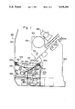
- FIG. 1 is a sectional view showing an embodiment of a chip collection apparatus according to the present invention
- FIG. 2 is a front elevation of the chip collecting and apparatus of FIG. 1;
- FIG. 3 is a front elevation for showing another embodiment of a chip collecting apparatus.
- a machine tool 501 such as a lathe, has a bed 502 as shown in FIG. 1.
- a guide rail 502a is formed on the bed 502 in a direction perpendicular to the paper of the Figure (the Z axis direction), and a tool rest 506 for having a tool installed thereon is movably supported by the guide rail 502a.
- a cover 507 is provided on a front face of the bed 502, that is to say, the left side of the Figure, covering the whole machine tool 501.
- a chip collecting apparatus 509 according to the present invention is provided at the lower end of the cover 507 in the Figure, at the front of the bed 502.
- the chip collecting apparatus 509 has a frame 510 which is formed as a whole in a box shape as shown in FIG. 1 and FIG. 2.
- Chip pans 511 are disposed on the upper portion of the frame 510 in FIG. 1, facing each other in a direction perpendicular to the paper in FIG. 1, that is, in the directions as shown by arrows WA and WB in FIG. 2.
- the chip pans 511 are formed obliquely in such a manner that the nearer portion to the center portion in FIG. 1 becomes lower, in the shape of a funnel as a whole, as shown in FIG. 2.
- a chip falling space 511a is formed at the center, having a width WL1 and a length WL2.
- Washing pipes 510a are formed at both sides of the chip pans 511 in FIG. 1 along the chip pans 511 in the direction perpendicular to the paper.
- a number of discharge holes are provided on each washing pipe 510a facing in the direction of the chip pans 511 in order to discharge a coolant 512 washing toward a chip pan face 511b.
- a change-over plate 513 extending over the entire length in the directions as shown by the arrows WA and WB in FIG. 2, is supported at both its sides via pins 510b on the frame 510, the change-over plate 513 being free to rotate and move in the directions as shown by the arrows WC and WD in FIG. 1.
- a driving cylinder 515 is provided near the pin 510b on the right side in FIG. 2 of the change-over plate 513 via bracket 514 fixed to the frame 510 between the change-over plate 513 and the frame 510.
- a rod 515a is provided with the driving cylinder 515, being free to project and drive in the directions as shown by the arrows WE and WF, and the top end of the rod 515a is connected with the change-over plate 513 such that the change-over plate 513 is free to rotate and move.
- a pair of chip conveyors 516 and 517 are disposed at below the change-over plate 513 in FIG. 1 via a partition plate 510c, conveying in the directions as shown by the arrows WA and WB (only a part of the chip conveyor 517 is shown in FIG. 1).
- the chip conveyors 516 and 517 project from the right side face of the frame 510 in the Figure to the outside, stretching to the right in FIG. 2 in the frame 510.
- the chip conveyors 516 and 517 extend in a gentle S-form at the upper portion of the Figure, being supported by legs 516b and 517b, and chip elimination orifices 516a and 517a are provided at the upper end, opening downward in the Figure.
- Two chip boxes 519 are in a row in a direction perpendicular to the paper face in FIG. 2, and are provided below the chip elimination orifices 516a and 517a, the chip boxes 519 being free to move via wheel 519a provided on the lower surfaces of the chip boxes 519.
- belts 516c and 517c having a edge and being provided for delivering the chips, are disposed between the left end portion of the frame 510 in FIG. 2 and the chip elimination orifices 516a and 517a of the chip conveyors 516 and 517, that is, in the directions as shown by the arrows WA and WB along the frame 510.
- Motors 520 are disposed at the end of the chip elimination orifices 516a and 517a.
- the motors 520 are provided for the respective chip conveyors 516 and 517. Therefore, the chip conveyors 516 and 517 can be selectively driven by selectively driving the motors 520.
- the workpiece in case a workpiece which is composed of a first material is machined by means of the machine tool 501, the workpiece is installed in the workpiece spindle 503 of the spindle stock 505.
- the predetermined machining such as turning, grinding and milling machining, is performed by means of the tool installed in the tool rest 506 in such a manner that the workpiece spindle 503 is rotated together with the workpiece.
- Chips 522 which are generated during the machining fall to the lower portion in FIG. 1 of the bed 502 and fall on the chip pans 511 of the chip collecting apparatus 509.
- a coolant 512 is always spouted from the washing pipe 510a to the chip pans 511, and the chips 522 which fall on the chip pans 511 are moved by being washed down, and fall into the chip falling space 511a formed at the center portion of the chip pan 511 by means of the spouting coolant 512.
- the change-over plate 513 is in a state in which the rod 515a of the driving cylinder 515 is projected in the direction as shown by the arrow WE.
- the change-over plate 513 is n a state rotated and moved on the pins 510b as its center in the direction as shown by the arrow WC.
- the chip falling space 511a is in a state communicating with the chip conveyor 516 on the left side in FIG. 1, and the chips 522 which fall on the change-over plate 513 fall on the belt 516c of the chip conveyor 516 by means of the coolant 512.
- the coolant 512 passes through the chip conveyor 516 and is retrieved in a drain tank, which is not shown in the Figure, and is fed to the washing pipe 510a by a circulating pump for reclamation. Moreover, when the coolant 512 falls toward the lower portion of FIG. 1 from the chip conveyor 516, the chips 522 remain on the belt 516c of the chip conveyor 516. Then the motor 620 of the chip conveyor 516 is rotated and driven, the belt 516c is moved and driven between the chip elimination orifice 516a and the chip falling space 511a, the chips 522 which fall on the belt 516c is conveyed to the chip elimination orifice 516a, and the chips 522 are discharged into the chip box 519 disposed below the elimination orifice 516a.
- the change-over plate 513 is kept in a state rotated and moved in the direction as shown by the arrow Wc in FIG. 1, and all the chips 522 which are generated during machining fall to the chip conveyor 516 side and are retrieved.
- the coolant 512 is flowed via the washing pipe 510a and the chips 522 which adhere to the chip pans 511 and which are composed of the first material are washed down, falling to the chip conveyor 516 side.
- the rod 515a of the driving cylinder 515 is retracted in the direction as shown by the arrow WF.
- the change-over plate 513 rotates and moves with retraction of the rod 515a on the pins 510b in the direction as shown by the arrow WD, the communication between the chip falling space 511a and the chip conveyor 516 being broken, and the chip falling space 511a and the chip conveyor 517 are communicated with each other.
- the motor 520 of the chip conveyor 517 side is rotated and driven, the belt 517c of the chip conveyor 517 side is driven, and the machining of the workpiece of the second material, which is different from the prior material, is started.
- the chips 522 which are generated during machining fall from the chip pans 511 to the change-over plate 513, being washed and flowing down by means of the coolant 512 as described before.
- the chips 522 are discharged from the change-over plate 513 to the chip conveyor 517 side and are expelled from the chip elimination orifice 517a into the other chip box 519 disposed below the elimination orifice 517a by the same procedure.
- the chips 522 fall to the chip conveyor 516 side by the change-over plate 513 and are stored in the chip box 519 in which the chips 522 were stored when the machining of the workpiece of the first material was last performed.
- the change-over plate 513 is provided at the machine tool side of the chip collecting apparatus 509, that is to say, at the chip collection side.
- the installation position of the change-over plate 513 is not restricted to the chip collection side.
- the change-over plate 513 can of course be provided at the chip elimination orifice side, at which the chips are thrown in the chip boxes.
- FIG. 3 The case in which the change-over plate is provided at the chip elimination orifice side will be explained in FIG. 3 hereinafter.
- the explanation of portions similar to the arrangement of FIGS. 1 and 2 is omitted by using the same reference numerals.
- a chip collecting apparatus 527 has a chip conveyor 523 as shown in FIG. 3. Only one chip conveyor is provided. This is different from the prior case in FIG. 1.
- a change-over plate 525 is supported by the frame 510, being free to rotate and move in the directions as shown by the arrows WG and WH via a shaft 525a.
- An arm 525b is provided on one end of the shaft 525a.
- the top end of a rod 526a of a driving cylinder 526 rotatably supported by the frame 510 is connected to the arm 525b so as to be free to rotate and move.
- two chip boxes 519 are disposed at the lower portion of the change-over plate 525 in the Figure.
- the chips 522 which are generated at the machine tool 501 fall together with coolant onto the chip conveyor 523 in the frame 510 as a regular chip collecting apparatus. Only chips 522 are conveyed to the chip elimination orifice 523a side provided at the upper right portion of the Figure, the chips 522 being separated from the coolant by means of the chip conveyor 523. The chips 522 which are conveyed to the chip elimination orifice 523a fall and are expelled onto the change-over plate 525 immediately. Regarding the change-over plate 525, the rod 526a of the driving cylinder 526 is properly projected and retracted according to the material of the workpiece which is being machined by the machine tool 501.
- the change-over plate 525 rotates and moves via the shaft 525a in the direction as shown by the arrow WH, and the chip elimination orifice 523a is connected with the chip box 519 at the right side of the Figure.
- the change-over plate 52 rotates and moves via the shaft 525a in the direction a shown by the arrow WG, and the chip elimination orifice 523a is connected with the chip box 519 at the left side of the Figure.
- the chips 522 are thrown and stored in the chip boxes 519 according to the material in such a manner that the driving cylinder 526 is driven on the basis of either manual operation or a machining program whenever the material of the workpiece to be machined changes, and the change-over plate 525 is properly switched in direction as shown by the arrow WG or WH.
Abstract
A chip collecting apparatus for a machine tool has two separate chip conveyors for chips of different materials. The chip collecting apparatus receives chips on fixed guide plates. Chips are washed from the fixed guide plates into a chip collecting area. In the chip collecting area is disposed a change-over plate for directing the chips from the guide plates onto either one of the chip conveyors. The change-over plate is pivotably moveable between different positions corresponding to the respective chip conveyors. In an alternative embodiment, only one chip conveyor is used, and the change-over plate is provided at the discharge end of the conveyor to discharge chips into either one of two chip collecting bins.
Description
This application is a divisional application of application Ser. No. 07/227,881 filed Aug. 3, 1988.
This invention relates to a chip collecting apparatus used for a machine tool such as a lathe, and a method of collecting chips.
In a conventional machine tool such a lathe, when the machining is performed on workpieces of different kinds of materials, differentiation of machining is not present, except for specific cases. Therefore, when the chip produced is collected it mixes with different kinds of chips.
This method is defective in the complication of the separation and classification of chips, for the object of effectively utilizing resources. In the case where a workpiece machined is completely different in character, such as metal and ceramic, a chip collecting apparatus capable of collecting and classifying the chip produced from the first is desirable.
It is an object of the present invention to provide a chip collecting apparatus capable of easily classifying and stocking the chip produced if the material to be machined changes.
Moreover, according to the present invention, a change-over plate is provided, being free to rotate and move in reciprocal directions at a chip collecting side such as a machine tool side, or at a chip elimination side such as a chip elimination orifice of a chip conveyor. A driving means for rotating and moving the change-over plate, such as a driving cylinder, are provided with the change-over plate.
With the above-described constitution, a chip different in material can be collected, properly sorting chips in such a manner that the driving means is driven according to the material to be machined to switch the change-over plate to reciprocal directions.
Accordingly, the collection and separation of chips can be easily performed, the reclamation of resources can be promoted, and chips different in properties such as ceramic and metal chips can be collected with an initial sorting operation.
FIG. 1 is a sectional view showing an embodiment of a chip collection apparatus according to the present invention;
FIG. 2 is a front elevation of the chip collecting and apparatus of FIG. 1; and
FIG. 3 is a front elevation for showing another embodiment of a chip collecting apparatus.
The present invention will be described in detail hereunder with reference to the accompanying drawings.
A machine tool 501, such as a lathe, has a bed 502 as shown in FIG. 1. A spindle stock 505, by which a workpiece spindle 503 is rotatably supported, is provided on the bed 502. A guide rail 502a is formed on the bed 502 in a direction perpendicular to the paper of the Figure (the Z axis direction), and a tool rest 506 for having a tool installed thereon is movably supported by the guide rail 502a. A cover 507 is provided on a front face of the bed 502, that is to say, the left side of the Figure, covering the whole machine tool 501. A chip collecting apparatus 509 according to the present invention is provided at the lower end of the cover 507 in the Figure, at the front of the bed 502.
The chip collecting apparatus 509 has a frame 510 which is formed as a whole in a box shape as shown in FIG. 1 and FIG. 2. Chip pans 511 are disposed on the upper portion of the frame 510 in FIG. 1, facing each other in a direction perpendicular to the paper in FIG. 1, that is, in the directions as shown by arrows WA and WB in FIG. 2. The chip pans 511 are formed obliquely in such a manner that the nearer portion to the center portion in FIG. 1 becomes lower, in the shape of a funnel as a whole, as shown in FIG. 2. A chip falling space 511a is formed at the center, having a width WL1 and a length WL2. Washing pipes 510a are formed at both sides of the chip pans 511 in FIG. 1 along the chip pans 511 in the direction perpendicular to the paper. A number of discharge holes, which are not shown in the Figure, are provided on each washing pipe 510a facing in the direction of the chip pans 511 in order to discharge a coolant 512 washing toward a chip pan face 511b.
At the lower portion of the chip falling space 511a in FIG. 1, a change-over plate 513, extending over the entire length in the directions as shown by the arrows WA and WB in FIG. 2, is supported at both its sides via pins 510b on the frame 510, the change-over plate 513 being free to rotate and move in the directions as shown by the arrows WC and WD in FIG. 1. A driving cylinder 515 is provided near the pin 510b on the right side in FIG. 2 of the change-over plate 513 via bracket 514 fixed to the frame 510 between the change-over plate 513 and the frame 510. A rod 515a is provided with the driving cylinder 515, being free to project and drive in the directions as shown by the arrows WE and WF, and the top end of the rod 515a is connected with the change-over plate 513 such that the change-over plate 513 is free to rotate and move.
A pair of chip conveyors 516 and 517 are disposed at below the change-over plate 513 in FIG. 1 via a partition plate 510c, conveying in the directions as shown by the arrows WA and WB (only a part of the chip conveyor 517 is shown in FIG. 1). The chip conveyors 516 and 517 project from the right side face of the frame 510 in the Figure to the outside, stretching to the right in FIG. 2 in the frame 510. The chip conveyors 516 and 517 extend in a gentle S-form at the upper portion of the Figure, being supported by legs 516b and 517b, and chip elimination orifices 516a and 517a are provided at the upper end, opening downward in the Figure. Two chip boxes 519 are in a row in a direction perpendicular to the paper face in FIG. 2, and are provided below the chip elimination orifices 516a and 517a, the chip boxes 519 being free to move via wheel 519a provided on the lower surfaces of the chip boxes 519. On the chip conveyors 516 and 517, belts 516c and 517c, having a edge and being provided for delivering the chips, are disposed between the left end portion of the frame 510 in FIG. 2 and the chip elimination orifices 516a and 517a of the chip conveyors 516 and 517, that is, in the directions as shown by the arrows WA and WB along the frame 510. Motors 520 are disposed at the end of the chip elimination orifices 516a and 517a. The motors 520 are provided for the respective chip conveyors 516 and 517. Therefore, the chip conveyors 516 and 517 can be selectively driven by selectively driving the motors 520.
With the above-described constitution of the machine tool 501 and the chip collecting apparatus 509, in case a workpiece which is composed of a first material is machined by means of the machine tool 501, the workpiece is installed in the workpiece spindle 503 of the spindle stock 505. In this state, the predetermined machining, such as turning, grinding and milling machining, is performed by means of the tool installed in the tool rest 506 in such a manner that the workpiece spindle 503 is rotated together with the workpiece. Chips 522 which are generated during the machining fall to the lower portion in FIG. 1 of the bed 502 and fall on the chip pans 511 of the chip collecting apparatus 509. A coolant 512 is always spouted from the washing pipe 510a to the chip pans 511, and the chips 522 which fall on the chip pans 511 are moved by being washed down, and fall into the chip falling space 511a formed at the center portion of the chip pan 511 by means of the spouting coolant 512.
The chips 522 which flow together with the coolant 512 into the chip falling space 511a fall on the change-over plate 513. At this point the change-over plate 513 is in a state in which the rod 515a of the driving cylinder 515 is projected in the direction as shown by the arrow WE. Accordingly, the change-over plate 513 is n a state rotated and moved on the pins 510b as its center in the direction as shown by the arrow WC. Then the chip falling space 511a is in a state communicating with the chip conveyor 516 on the left side in FIG. 1, and the chips 522 which fall on the change-over plate 513 fall on the belt 516c of the chip conveyor 516 by means of the coolant 512. The coolant 512 passes through the chip conveyor 516 and is retrieved in a drain tank, which is not shown in the Figure, and is fed to the washing pipe 510a by a circulating pump for reclamation. Moreover, when the coolant 512 falls toward the lower portion of FIG. 1 from the chip conveyor 516, the chips 522 remain on the belt 516c of the chip conveyor 516. Then the motor 620 of the chip conveyor 516 is rotated and driven, the belt 516c is moved and driven between the chip elimination orifice 516a and the chip falling space 511a, the chips 522 which fall on the belt 516c is conveyed to the chip elimination orifice 516a, and the chips 522 are discharged into the chip box 519 disposed below the elimination orifice 516a.
In this way, while the workpiece which is composed of one kind of material is being machined, the change-over plate 513 is kept in a state rotated and moved in the direction as shown by the arrow Wc in FIG. 1, and all the chips 522 which are generated during machining fall to the chip conveyor 516 side and are retrieved.
In case the material of a workpiece to be machined changes from the first material into a second material, before the start of machining, the coolant 512 is flowed via the washing pipe 510a and the chips 522 which adhere to the chip pans 511 and which are composed of the first material are washed down, falling to the chip conveyor 516 side. When this washing operation finishes, the rod 515a of the driving cylinder 515 is retracted in the direction as shown by the arrow WF. Then the change-over plate 513 rotates and moves with retraction of the rod 515a on the pins 510b in the direction as shown by the arrow WD, the communication between the chip falling space 511a and the chip conveyor 516 being broken, and the chip falling space 511a and the chip conveyor 517 are communicated with each other.
In this state the motor 520 of the chip conveyor 517 side is rotated and driven, the belt 517c of the chip conveyor 517 side is driven, and the machining of the workpiece of the second material, which is different from the prior material, is started. Then the chips 522 which are generated during machining fall from the chip pans 511 to the change-over plate 513, being washed and flowing down by means of the coolant 512 as described before. Moreover, the chips 522 are discharged from the change-over plate 513 to the chip conveyor 517 side and are expelled from the chip elimination orifice 517a into the other chip box 519 disposed below the elimination orifice 517a by the same procedure.
In case the workpiece which is composed of the first material is machined again when the machining of the workpiece being different in material has been performed and the machining finishes, as in the above-described case, washing by the washing pipe 510a is performed for a predetermined time, and thereafter the driving cylinder 515 is again driven to rotate and move the change-over plate 513 in the direction as shown by the arrow WC. The chip falling space 511a and the chip conveyor 516 are communicated with each other, and the communicating state is broken between the chip conveyor 517 and the chip falling space 511a. In this state, when the machining is started on the workpiece of the first material, the chips 522 fall to the chip conveyor 516 side by the change-over plate 513 and are stored in the chip box 519 in which the chips 522 were stored when the machining of the workpiece of the first material was last performed.
In the above-described embodiment, it was mentioned that the change-over plate 513 is provided at the machine tool side of the chip collecting apparatus 509, that is to say, at the chip collection side. However, the installation position of the change-over plate 513 is not restricted to the chip collection side. The change-over plate 513 can of course be provided at the chip elimination orifice side, at which the chips are thrown in the chip boxes. The case in which the change-over plate is provided at the chip elimination orifice side will be explained in FIG. 3 hereinafter. The explanation of portions similar to the arrangement of FIGS. 1 and 2 is omitted by using the same reference numerals.
A chip collecting apparatus 527 has a chip conveyor 523 as shown in FIG. 3. Only one chip conveyor is provided. This is different from the prior case in FIG. 1. Below a chip elimination orifice 523a of the chip conveyor 523, a change-over plate 525 is supported by the frame 510, being free to rotate and move in the directions as shown by the arrows WG and WH via a shaft 525a. An arm 525b is provided on one end of the shaft 525a. The top end of a rod 526a of a driving cylinder 526 rotatably supported by the frame 510 is connected to the arm 525b so as to be free to rotate and move. Moreover, two chip boxes 519 are disposed at the lower portion of the change-over plate 525 in the Figure.
With the above-described constitution of the chip collecting apparatus 527, the chips 522 which are generated at the machine tool 501 fall together with coolant onto the chip conveyor 523 in the frame 510 as a regular chip collecting apparatus. Only chips 522 are conveyed to the chip elimination orifice 523a side provided at the upper right portion of the Figure, the chips 522 being separated from the coolant by means of the chip conveyor 523. The chips 522 which are conveyed to the chip elimination orifice 523a fall and are expelled onto the change-over plate 525 immediately. Regarding the change-over plate 525, the rod 526a of the driving cylinder 526 is properly projected and retracted according to the material of the workpiece which is being machined by the machine tool 501. When the rod 526a projects, the change-over plate 525 rotates and moves via the shaft 525a in the direction as shown by the arrow WH, and the chip elimination orifice 523a is connected with the chip box 519 at the right side of the Figure. When the rod 526a retracts, the change-over plate 52 rotates and moves via the shaft 525a in the direction a shown by the arrow WG, and the chip elimination orifice 523a is connected with the chip box 519 at the left side of the Figure. Accordingly, the chips 522 are thrown and stored in the chip boxes 519 according to the material in such a manner that the driving cylinder 526 is driven on the basis of either manual operation or a machining program whenever the material of the workpiece to be machined changes, and the change-over plate 525 is properly switched in direction as shown by the arrow WG or WH.
The present invention has been explained on the basis of the embodiments presented herein. However, the embodiments which are described in the present specification are illustrative and not limiting. The scope of the invention is designated by the accompanying claims and is not restricted by the description of the specific embodiments. Accordingly, all the transformations and changes belonging to the claims are included in the scope of the present invention.
Claims (3)
1. A chip collecting apparatus, comprising:
a frame;
a fixed guide plate for receiving chips thereon provided on said frame, said fixed guide plate extending obliquely downward, and a chip falling space being defined below said fixed guide plate;
a washing means disposed at an upper portion of said fixed guide plate for supplying washing liquid to the surface of said fixed guide plate for washing chips on said fixed guide plate into said chip falling space;
two selectively drivable chip conveyors disposed parallel to each other at a lower portion of said chip falling space;
a change-over plate having a pivot connected at a midpoint thereof pivotably disposed in said chip falling space for pivoting movement in opposite directions between a first position directing chips onto one said chip conveyor and a second position directing chips onto the other said chip conveyor; and
a means for pivotably driving said change-over plate between said first and second position, said means for pivotably driving said change-over plate comprising a piston and cylinder connected to said change-over plate.
2. The chip collecting apparatus as set forth in claim 1, and further comprising:
a second fixed guide plate for receiving chips thereon provided on said frame, said change-over plate being pivotably disposed in said chip falling space between said fixed guide plates.
3. The chip collecting apparatus as set forth in claim 2, wherein said fixed guide plates extend longitudinally parallel to said chip conveyors, and said change-over plate extends longitudinally parallel to said chip conveyors and said fixed guide plates.
Applications Claiming Priority (10)
| Application Number | Priority Date | Filing Date | Title |
|---|---|---|---|
| JP62-175713 | 1987-07-14 | ||
| JP62-119485 | 1987-08-04 | ||
| JP62-194766 | 1987-08-04 | ||
| JP1987119485U JPH0511956Y2 (en) | 1987-08-04 | 1987-08-04 | |
| JP62-119486 | 1987-08-04 | ||
| JP1987119484U JPH0511955Y2 (en) | 1987-08-04 | 1987-08-04 | |
| JP62194766A JPS6440254A (en) | 1987-08-04 | 1987-08-04 | Chip collecting device |
| JP62-119484 | 1987-08-04 | ||
| JP11948687U JPS6426152U (en) | 1987-08-04 | 1987-08-04 | |
| JP1987175713U JPH0181235U (en) | 1987-11-17 | 1987-11-17 |
Related Parent Applications (1)
| Application Number | Title | Priority Date | Filing Date |
|---|---|---|---|
| US07/227,881 Division US5006685A (en) | 1987-08-04 | 1988-08-03 | Machine tool with grinding function and truing/dressing method of grinding stone using it |
Publications (1)
| Publication Number | Publication Date |
|---|---|
| US5078256A true US5078256A (en) | 1992-01-07 |
Family
ID=27526843
Family Applications (2)
| Application Number | Title | Priority Date | Filing Date |
|---|---|---|---|
| US07/227,881 Expired - Lifetime US5006685A (en) | 1987-08-04 | 1988-08-03 | Machine tool with grinding function and truing/dressing method of grinding stone using it |
| US07/461,550 Expired - Fee Related US5078256A (en) | 1987-08-04 | 1990-01-05 | Machine tool having a chip collecting apparatus |
Family Applications Before (1)
| Application Number | Title | Priority Date | Filing Date |
|---|---|---|---|
| US07/227,881 Expired - Lifetime US5006685A (en) | 1987-08-04 | 1988-08-03 | Machine tool with grinding function and truing/dressing method of grinding stone using it |
Country Status (2)
| Country | Link |
|---|---|
| US (2) | US5006685A (en) |
| DE (1) | DE3826277A1 (en) |
Cited By (30)
| Publication number | Priority date | Publication date | Assignee | Title |
|---|---|---|---|---|
| US5205686A (en) * | 1992-02-07 | 1993-04-27 | Fadal Engineering Co. | Apparatus and method for hydraulically fed cuttings removal and collection for cutting type machine tools |
| US5263800A (en) * | 1992-08-20 | 1993-11-23 | Chen Chih Hung | Work table of tooling machine |
| US5265382A (en) * | 1992-01-21 | 1993-11-30 | Kyung Park | Glass plate chamfering machine capable of chamfering and grinding successively |
| US5294220A (en) * | 1993-06-22 | 1994-03-15 | Ohmstede, Inc. | Machining apparatus |
| US5480398A (en) * | 1992-05-01 | 1996-01-02 | Hemostatic Surgery Corporation | Endoscopic instrument with disposable auto-regulating heater |
| US5480397A (en) * | 1992-05-01 | 1996-01-02 | Hemostatic Surgery Corporation | Surgical instrument with auto-regulating heater and method of using same |
| US5586848A (en) * | 1995-05-02 | 1996-12-24 | The Gleason Works | Machine tool chip removal system |
| US5593406A (en) * | 1992-05-01 | 1997-01-14 | Hemostatic Surgery Corporation | Endoscopic instrument with auto-regulating heater and method of using same |
| US5676030A (en) * | 1995-08-14 | 1997-10-14 | Crudgington Machine Tools, Inc. | Multi-spindle CNC lathe |
| US5683210A (en) * | 1995-07-26 | 1997-11-04 | Ford Global Technologies, Inc. | Machine tool chip flushing apparatus and method |
| US5781983A (en) * | 1994-06-29 | 1998-07-21 | Gruener; Magnus | Machining center |
| US5858218A (en) * | 1996-12-16 | 1999-01-12 | Kennametal Inc. | Machine tool coolant reclamation system employing a conveyor discharging separated solids onto an impingement screen |
| CN1047975C (en) * | 1993-04-27 | 2000-01-05 | 陈伯勋 | Working talbe for tool machine |
| US6357576B1 (en) * | 1999-04-14 | 2002-03-19 | Enomoto Industry Co., Ltd | Chip conveyors and apparatus for separating and collecting chips |
| US6533099B2 (en) | 2001-03-14 | 2003-03-18 | Hytrol Conveyor Company, Inc. | Article sorting system and method |
| US6679659B1 (en) * | 2000-01-07 | 2004-01-20 | Deckel Maho Seebach Gmbh | Milling machine comprising a rotating, drivable tool spindle |
| US20040122446A1 (en) * | 2002-12-20 | 2004-06-24 | Solar Matthew S. | Organ access device and method |
| US20050031427A1 (en) * | 2003-07-15 | 2005-02-10 | Kazuyuki Hiramoto | Chip discharging device for machine tool |
| US20080060492A1 (en) * | 2006-09-07 | 2008-03-13 | Murata Machinery, Ltd. | Lathe |
| US20080062788A1 (en) * | 2006-09-07 | 2008-03-13 | Kang Uk-Song | Parallel bit test circuit and method |
| US20090250082A1 (en) * | 2008-02-07 | 2009-10-08 | Miller Edward B | Conveyor debris washing apparatus and methods |
| US20090290948A1 (en) * | 2006-08-24 | 2009-11-26 | Sirona Dental Systems Gmbh | Machining device, particularly for the production of tooth replacement parts or models thereof |
| US20100012564A1 (en) * | 2004-07-02 | 2010-01-21 | Mayfran International B.V. | Device for holding and separating chippings and cooling liquid accumulating on machine tools (conveyance) |
| US20100015897A1 (en) * | 2006-06-14 | 2010-01-21 | Bernd Moeller | Spindle with draw rod and current conductor |
| US20150023752A1 (en) * | 2013-06-26 | 2015-01-22 | Dmg Mori Seiki Co., Ltd. | Chip disposal device of machine tool |
| US9694459B2 (en) * | 2015-06-04 | 2017-07-04 | Dmg Mori Co., Ltd. | Chip discharge device of machine tool |
| CN106965034A (en) * | 2017-04-18 | 2017-07-21 | 苏州亚思科精密数控有限公司 | A kind of numerically controlled machine |
| US10981732B2 (en) | 2013-01-18 | 2021-04-20 | United Sortation Solutions, Llc | Device for reliably moving article from conveyor surface |
| US11628386B2 (en) * | 2017-09-13 | 2023-04-18 | Bunri Incorporation | Filtration device |
| US11964353B2 (en) * | 2019-07-10 | 2024-04-23 | Leen David Steed | Machine debris clean out system |
Families Citing this family (27)
| Publication number | Priority date | Publication date | Assignee | Title |
|---|---|---|---|---|
| US5091622A (en) * | 1989-05-10 | 1992-02-25 | Mitsubishi Denki K.K. | Compound machining method and apparatus |
| DE69116901T2 (en) * | 1990-02-27 | 1996-07-18 | Toshiba Kawasaki Kk | Robot control |
| WO1997031756A1 (en) * | 1994-09-29 | 1997-09-04 | Kitamura Machinery Co., Ltd. | Machine tool for combined working |
| WO1999007507A2 (en) * | 1997-08-12 | 1999-02-18 | Arizona Board Of Regents, A Body Corporate Acting On Behalf Of Arizona State University | Method and apparatus for hard machining |
| US6733365B1 (en) * | 1997-08-12 | 2004-05-11 | Arizona Board Of Regents | Method and apparatus for hard machining |
| DE19754887A1 (en) * | 1997-12-10 | 1999-06-24 | Vollmer Werke Maschf | Method and device for EDM dressing a grinding wheel |
| FR2784319B1 (en) * | 1998-10-13 | 2000-12-15 | Framatome Connectors France | DEVICE FOR SELECTING AND SEPARATING SEPARATELY THE CHIPS FORMED DURING THE MACHINING OF WORKPIECES |
| US6783428B1 (en) * | 1999-01-18 | 2004-08-31 | Nsk Ltd. | Method for forming grooves on workpiece and for dressing a grindstone used in the groove formation |
| US6361410B1 (en) * | 1999-01-18 | 2002-03-26 | Nsk Ltd. | Grinding apparatus for forming grooves on a workpiece and a method for dressing a grindstone used in the apparatus |
| US6566623B2 (en) * | 2001-05-30 | 2003-05-20 | Harvest Precision Components, Inc. | Method and apparatus for electric discharge machining with a dressing tool |
| JP3987380B2 (en) * | 2002-05-31 | 2007-10-10 | ヤマザキマザック株式会社 | Tool holder for turret lathe |
| JP2004034160A (en) * | 2002-06-28 | 2004-02-05 | Yamazaki Mazak Corp | Turret for turret lathe |
| KR100879345B1 (en) * | 2002-07-13 | 2009-01-19 | 주식회사 포스코 | Grinding stone dressing apparatus |
| US6935003B2 (en) * | 2003-02-28 | 2005-08-30 | National University Of Singapore | Compound fabrication process and apparatus |
| BRPI0417290B1 (en) | 2003-12-23 | 2019-02-19 | Diamond Innovations, Inc. | METHOD FOR RETIFYING A FERROUS CYLINDER |
| JP2005246499A (en) * | 2004-03-01 | 2005-09-15 | Toyoda Mach Works Ltd | Truing method and device |
| DE102004026917B4 (en) * | 2004-06-01 | 2007-08-30 | Sirona Dental Systems Gmbh | Method, tool and processing machine for the production of dental prostheses |
| JP4506461B2 (en) * | 2004-12-28 | 2010-07-21 | トヨタ自動車株式会社 | Precision machining apparatus and precision machining method |
| JP4839720B2 (en) * | 2005-08-04 | 2011-12-21 | トヨタ自動車株式会社 | Precision processing equipment |
| EP1872962B1 (en) * | 2006-06-23 | 2011-09-28 | Müller Martini Holding AG | Stapling device for printed products having a ceramic component |
| US7992272B2 (en) | 2007-05-29 | 2011-08-09 | Metem Corporation | Method and apparatus for milling thermal barrier coated metals |
| JP5014970B2 (en) * | 2007-12-12 | 2012-08-29 | ヤマザキマザック株式会社 | Workpiece loading / unloading device for complex machining lathe |
| JP5857660B2 (en) * | 2011-06-27 | 2016-02-10 | 株式会社ジェイテクト | Grinding machine truing device |
| DE102018122682A1 (en) * | 2018-09-17 | 2020-03-19 | Diahon Werkzeuge Gmbh & Co. Kg | Method for dressing a honing tool, device for using the method and processing machine equipped with the device, honing stone and honing tool |
| US10926369B2 (en) | 2019-04-25 | 2021-02-23 | Gilbert Melbye Lea | Adjustable tool sharpening platform |
| CN110524253A (en) * | 2019-08-23 | 2019-12-03 | 宝鸡保德利电气设备有限责任公司 | High iron catenary aluminum alloy spare part automatic polishing equipment |
| CN110509129B (en) * | 2019-09-18 | 2024-03-12 | 合肥工业大学 | Self-adaptive burn-proof cylindrical grinding machine |
Citations (7)
| Publication number | Priority date | Publication date | Assignee | Title |
|---|---|---|---|---|
| US771836A (en) * | 1903-07-20 | 1904-10-11 | Edwin M Schantz | Off-bear table for sawmills. |
| US1616151A (en) * | 1923-03-30 | 1927-02-01 | Pratt & Whitney Co | Chip and blank separator for lathes |
| US2124216A (en) * | 1936-07-03 | 1938-07-19 | Tessky Karl | Lathe |
| US3098332A (en) * | 1960-10-05 | 1963-07-23 | Sutton Shoe Machinery Co | Grindings collector |
| JPS59124542A (en) * | 1982-12-28 | 1984-07-18 | Enomoto Kogyo Kk | Chip conveyor |
| GB2154914A (en) * | 1981-12-11 | 1985-09-18 | Romi Ind | Turning machine with chip disposal |
| US4804078A (en) * | 1985-06-13 | 1989-02-14 | Meccanizzazione Postale E Automazione Spa (Mpa) | Sorting device for conveyor belt systems |
Family Cites Families (6)
| Publication number | Priority date | Publication date | Assignee | Title |
|---|---|---|---|---|
| US3398253A (en) * | 1965-10-19 | 1968-08-20 | F Jos Lamb Company Inc | Grinding machine with electric discharge machining mechanism for reshaping crush roll |
| JPS5217292A (en) * | 1975-07-31 | 1977-02-09 | Toyoda Mach Works Ltd | Grinding machine |
| JPS59169720A (en) * | 1983-03-16 | 1984-09-25 | Inoue Japax Res Inc | Machining center for electric machining |
| WO1986000037A1 (en) * | 1984-06-14 | 1986-01-03 | Yugenkaisha Ohyojiki Kenkyujo | Cutting and grinding method using conductive grinding wheel |
| DE3522977A1 (en) * | 1985-06-27 | 1987-01-08 | Buderus Ag | METHOD FOR PROFILE PROFILING OF A WORKPIECE |
| DE3533002A1 (en) * | 1985-09-16 | 1987-03-26 | Agie Ag Ind Elektronik | ELECTROEROSION METHOD AND ELECTROEROSION MACHINE FOR CARRYING OUT THE METHOD |
-
1988
- 1988-08-02 DE DE3826277A patent/DE3826277A1/en active Granted
- 1988-08-03 US US07/227,881 patent/US5006685A/en not_active Expired - Lifetime
-
1990
- 1990-01-05 US US07/461,550 patent/US5078256A/en not_active Expired - Fee Related
Patent Citations (7)
| Publication number | Priority date | Publication date | Assignee | Title |
|---|---|---|---|---|
| US771836A (en) * | 1903-07-20 | 1904-10-11 | Edwin M Schantz | Off-bear table for sawmills. |
| US1616151A (en) * | 1923-03-30 | 1927-02-01 | Pratt & Whitney Co | Chip and blank separator for lathes |
| US2124216A (en) * | 1936-07-03 | 1938-07-19 | Tessky Karl | Lathe |
| US3098332A (en) * | 1960-10-05 | 1963-07-23 | Sutton Shoe Machinery Co | Grindings collector |
| GB2154914A (en) * | 1981-12-11 | 1985-09-18 | Romi Ind | Turning machine with chip disposal |
| JPS59124542A (en) * | 1982-12-28 | 1984-07-18 | Enomoto Kogyo Kk | Chip conveyor |
| US4804078A (en) * | 1985-06-13 | 1989-02-14 | Meccanizzazione Postale E Automazione Spa (Mpa) | Sorting device for conveyor belt systems |
Cited By (38)
| Publication number | Priority date | Publication date | Assignee | Title |
|---|---|---|---|---|
| US5265382A (en) * | 1992-01-21 | 1993-11-30 | Kyung Park | Glass plate chamfering machine capable of chamfering and grinding successively |
| US5205686A (en) * | 1992-02-07 | 1993-04-27 | Fadal Engineering Co. | Apparatus and method for hydraulically fed cuttings removal and collection for cutting type machine tools |
| US5480398A (en) * | 1992-05-01 | 1996-01-02 | Hemostatic Surgery Corporation | Endoscopic instrument with disposable auto-regulating heater |
| US5480397A (en) * | 1992-05-01 | 1996-01-02 | Hemostatic Surgery Corporation | Surgical instrument with auto-regulating heater and method of using same |
| US5593406A (en) * | 1992-05-01 | 1997-01-14 | Hemostatic Surgery Corporation | Endoscopic instrument with auto-regulating heater and method of using same |
| US5263800A (en) * | 1992-08-20 | 1993-11-23 | Chen Chih Hung | Work table of tooling machine |
| CN1047975C (en) * | 1993-04-27 | 2000-01-05 | 陈伯勋 | Working talbe for tool machine |
| US5294220A (en) * | 1993-06-22 | 1994-03-15 | Ohmstede, Inc. | Machining apparatus |
| US5781983A (en) * | 1994-06-29 | 1998-07-21 | Gruener; Magnus | Machining center |
| US5586848A (en) * | 1995-05-02 | 1996-12-24 | The Gleason Works | Machine tool chip removal system |
| US5683210A (en) * | 1995-07-26 | 1997-11-04 | Ford Global Technologies, Inc. | Machine tool chip flushing apparatus and method |
| US5676030A (en) * | 1995-08-14 | 1997-10-14 | Crudgington Machine Tools, Inc. | Multi-spindle CNC lathe |
| US5918514A (en) | 1995-08-14 | 1999-07-06 | Crudgington Machine Tools, Inc. | Multi-spindle CNC lathe |
| US5858218A (en) * | 1996-12-16 | 1999-01-12 | Kennametal Inc. | Machine tool coolant reclamation system employing a conveyor discharging separated solids onto an impingement screen |
| US6357576B1 (en) * | 1999-04-14 | 2002-03-19 | Enomoto Industry Co., Ltd | Chip conveyors and apparatus for separating and collecting chips |
| US6679659B1 (en) * | 2000-01-07 | 2004-01-20 | Deckel Maho Seebach Gmbh | Milling machine comprising a rotating, drivable tool spindle |
| US6688459B1 (en) | 2001-03-14 | 2004-02-10 | Hytrol Conveyor Company, Inc. | Article sorting system and method |
| US6533099B2 (en) | 2001-03-14 | 2003-03-18 | Hytrol Conveyor Company, Inc. | Article sorting system and method |
| US6578697B2 (en) | 2001-03-14 | 2003-06-17 | Hytrol Conveyor Company, Inc. | Article sorting system and method |
| US20040122446A1 (en) * | 2002-12-20 | 2004-06-24 | Solar Matthew S. | Organ access device and method |
| US20050031427A1 (en) * | 2003-07-15 | 2005-02-10 | Kazuyuki Hiramoto | Chip discharging device for machine tool |
| US7044696B2 (en) * | 2003-07-15 | 2006-05-16 | Mori Seiki Co., Ltd. | Chip discharging device for machine tool |
| US20100012564A1 (en) * | 2004-07-02 | 2010-01-21 | Mayfran International B.V. | Device for holding and separating chippings and cooling liquid accumulating on machine tools (conveyance) |
| US20100015897A1 (en) * | 2006-06-14 | 2010-01-21 | Bernd Moeller | Spindle with draw rod and current conductor |
| US8287334B2 (en) | 2006-06-14 | 2012-10-16 | Paul Mueller Gmbh & Co. Kg Unternehmensbeteiligungen | Spindle with draw rod and current conductor |
| US8622668B2 (en) * | 2006-08-24 | 2014-01-07 | Sirona Dental Systems Gmbh | Machining device, particularly for the production of tooth replacement parts or models thereof |
| US20090290948A1 (en) * | 2006-08-24 | 2009-11-26 | Sirona Dental Systems Gmbh | Machining device, particularly for the production of tooth replacement parts or models thereof |
| US20080060492A1 (en) * | 2006-09-07 | 2008-03-13 | Murata Machinery, Ltd. | Lathe |
| US7717019B2 (en) * | 2006-09-07 | 2010-05-18 | Murata Machinery, Ltd. | Lathe |
| US20080062788A1 (en) * | 2006-09-07 | 2008-03-13 | Kang Uk-Song | Parallel bit test circuit and method |
| US20090250082A1 (en) * | 2008-02-07 | 2009-10-08 | Miller Edward B | Conveyor debris washing apparatus and methods |
| US10981732B2 (en) | 2013-01-18 | 2021-04-20 | United Sortation Solutions, Llc | Device for reliably moving article from conveyor surface |
| US20150023752A1 (en) * | 2013-06-26 | 2015-01-22 | Dmg Mori Seiki Co., Ltd. | Chip disposal device of machine tool |
| US9339907B2 (en) * | 2013-06-26 | 2016-05-17 | Dmg Mori Seiki Co., Ltd. | Chip disposal device of machine tool |
| US9694459B2 (en) * | 2015-06-04 | 2017-07-04 | Dmg Mori Co., Ltd. | Chip discharge device of machine tool |
| CN106965034A (en) * | 2017-04-18 | 2017-07-21 | 苏州亚思科精密数控有限公司 | A kind of numerically controlled machine |
| US11628386B2 (en) * | 2017-09-13 | 2023-04-18 | Bunri Incorporation | Filtration device |
| US11964353B2 (en) * | 2019-07-10 | 2024-04-23 | Leen David Steed | Machine debris clean out system |
Also Published As
| Publication number | Publication date |
|---|---|
| DE3826277A1 (en) | 1989-02-16 |
| US5006685A (en) | 1991-04-09 |
Similar Documents
| Publication | Publication Date | Title |
|---|---|---|
| US5078256A (en) | Machine tool having a chip collecting apparatus | |
| US4665785A (en) | Trim press | |
| CN113334133B (en) | Multi-station numerical control machining tool | |
| US4727785A (en) | Cutting machine | |
| CN110306300A (en) | Full-automatic four sides sewing machine | |
| CN108480660B (en) | Full-automatic double-ended truning fixture | |
| CN114179180B (en) | Chopstick slitting and forming method | |
| US6138818A (en) | Workpiece inversion system for milling machines | |
| CN112428115A (en) | Machining equipment for automatic grinding interfaces of hinges in batches | |
| CN101462238A (en) | Automatic loading and unloading device for processing inner shape of sheet material | |
| CN109759641B (en) | Short material circular saw equipment | |
| CN111590141A (en) | Flat workpiece cutting device | |
| CN213470468U (en) | Numerical control machine tool | |
| CN219403826U (en) | Sorting line of arc grinding machine | |
| CN220445873U (en) | Automatic grinding and planing processing table with chip collecting function | |
| CN215237864U (en) | Discharging mechanism and horizontal lathe | |
| CN219379935U (en) | Unloading device of processing lathe | |
| CN220466942U (en) | Feeding mechanism and drying equipment | |
| CN218874401U (en) | Automatic chamfer burring equipment of work piece | |
| CN219967567U (en) | Feeding and discharging device for grinding cone angle of ceramic comb teeth and grinding machine | |
| CN220093927U (en) | Feeding and discharging device of numerical control machine tool | |
| CN215659218U (en) | Milling machine with waste cleaning device | |
| CN219617132U (en) | Plane polishing machine | |
| CN216680993U (en) | Automatic special knurling machine | |
| JPH06247523A (en) | Auxiliary device for chip conveyer |
Legal Events
| Date | Code | Title | Description |
|---|---|---|---|
| REMI | Maintenance fee reminder mailed | ||
| LAPS | Lapse for failure to pay maintenance fees | ||
| FP | Lapsed due to failure to pay maintenance fee |
Effective date: 19960110 |
|
| STCH | Information on status: patent discontinuation |
Free format text: PATENT EXPIRED DUE TO NONPAYMENT OF MAINTENANCE FEES UNDER 37 CFR 1.362 |