US5073714A - Method and apparatus for detecting amplitude and frequency of web flutter using infrared optical sensor - Google Patents
Method and apparatus for detecting amplitude and frequency of web flutter using infrared optical sensor Download PDFInfo
- Publication number
- US5073714A US5073714A US07/527,216 US52721690A US5073714A US 5073714 A US5073714 A US 5073714A US 52721690 A US52721690 A US 52721690A US 5073714 A US5073714 A US 5073714A
- Authority
- US
- United States
- Prior art keywords
- web
- light
- infrared light
- flutter
- plane
- Prior art date
- Legal status (The legal status is an assumption and is not a legal conclusion. Google has not performed a legal analysis and makes no representation as to the accuracy of the status listed.)
- Expired - Fee Related
Links
- 238000000034 method Methods 0.000 title claims description 13
- 230000003287 optical effect Effects 0.000 title 1
- 230000033001 locomotion Effects 0.000 claims description 8
- 238000012544 monitoring process Methods 0.000 claims description 4
- 230000001154 acute effect Effects 0.000 claims 5
- 230000001747 exhibiting effect Effects 0.000 claims 1
- 238000001914 filtration Methods 0.000 claims 1
- 238000005259 measurement Methods 0.000 description 8
- 239000000523 sample Substances 0.000 description 4
- 239000000428 dust Substances 0.000 description 2
- 230000000694 effects Effects 0.000 description 2
- 239000000835 fiber Substances 0.000 description 2
- 238000004519 manufacturing process Methods 0.000 description 2
- 239000000463 material Substances 0.000 description 2
- 238000009825 accumulation Methods 0.000 description 1
- 238000011088 calibration curve Methods 0.000 description 1
- 238000011109 contamination Methods 0.000 description 1
- 230000001419 dependent effect Effects 0.000 description 1
- 230000003292 diminished effect Effects 0.000 description 1
- 238000001035 drying Methods 0.000 description 1
- 239000012528 membrane Substances 0.000 description 1
- 238000012986 modification Methods 0.000 description 1
- 230000004048 modification Effects 0.000 description 1
- 230000003534 oscillatory effect Effects 0.000 description 1
- 230000035945 sensitivity Effects 0.000 description 1
- 239000007787 solid Substances 0.000 description 1
- 238000009423 ventilation Methods 0.000 description 1
Images
Classifications
-
- G—PHYSICS
- G01—MEASURING; TESTING
- G01S—RADIO DIRECTION-FINDING; RADIO NAVIGATION; DETERMINING DISTANCE OR VELOCITY BY USE OF RADIO WAVES; LOCATING OR PRESENCE-DETECTING BY USE OF THE REFLECTION OR RERADIATION OF RADIO WAVES; ANALOGOUS ARRANGEMENTS USING OTHER WAVES
- G01S17/00—Systems using the reflection or reradiation of electromagnetic waves other than radio waves, e.g. lidar systems
- G01S17/87—Combinations of systems using electromagnetic waves other than radio waves
- G01S17/875—Combinations of systems using electromagnetic waves other than radio waves for determining attitude
-
- D—TEXTILES; PAPER
- D21—PAPER-MAKING; PRODUCTION OF CELLULOSE
- D21G—CALENDERS; ACCESSORIES FOR PAPER-MAKING MACHINES
- D21G9/00—Other accessories for paper-making machines
- D21G9/0009—Paper-making control systems
-
- G—PHYSICS
- G01—MEASURING; TESTING
- G01S—RADIO DIRECTION-FINDING; RADIO NAVIGATION; DETERMINING DISTANCE OR VELOCITY BY USE OF RADIO WAVES; LOCATING OR PRESENCE-DETECTING BY USE OF THE REFLECTION OR RERADIATION OF RADIO WAVES; ANALOGOUS ARRANGEMENTS USING OTHER WAVES
- G01S17/00—Systems using the reflection or reradiation of electromagnetic waves other than radio waves, e.g. lidar systems
- G01S17/88—Lidar systems specially adapted for specific applications
Definitions
- This invention pertains to a method and apparatus for detecting and measuring the flutter of free-standing web material in a web handling machine such as a paper web in a papermaking machine, and more particularly, by a method and device wherein the web flutter is determined from infrared light scattered from the web.
- U.S. Pat. No. 4,501,642 to Wells discloses a method of paper tension control including a light source directing a light normal to the nominal plane of the web, and a light detector for detecting the light reflected from the web.
- this device cannot monitor paper web flutter with significant amplitude because as the web oscillates through its motions, the reflected light quickly surpasses the range of the light detector.
- the use of visible light is undesirable because, unless the measurement is taken in total darkness, the light sensor is also sensitive to ambient light, thereby confusing the measurements. Also, the sensor sensitivity can be quickly diminished due to the accumulation of fiber dust.
- U.S. Pat. No. 4,637,727 to Ahola discloses a device for analyzing the reciprocating motion of a paper web by measuring the time required for a light beam to strike the web and return to the transmitter. This device needs very accurate elements for precise measurements, and in a manufacturing environment is susceptible to machine vibration and dust contamination. Furthermore, it also discloses a light sensor With limited angular range.
- U.S. Pat. No. 3,703,097 uses an array of noncontacting proximity sensors to measure the flatness of sheet material. To remove substantially all internal compressive strains, the sheet is placed in tension, and the proximity sensors disposed at a base line are used to obtain a first set of measurements for the sheet on one surface. The sheet is reversed and a second set of measurements are obtained for the second surface of the sheet. The two sets of measurements are averaged to obtain an accurate transversal profile for the sheet.
- a further objective is to provide a device which has few components so that it can be placed easily along the paper web in a papermaking machine.
- the device should be able to monitor web flutter independent of web location and orientation.
- web flutter is detected by sensing infrared light scattered from the web in a direction and at a distance normal to the nominal web plane and then determining the intensity of the infrared light. This intensity is proportional to the instantaneous distance between the infrared light sensor and the web.
- the infrared light incident on and scattered by the web is generated from a plurality of infrared light sources disposed at preselected locations with respect to the sensor, and positioned so that light incident from at least one of the sources is sensed by the sensor.
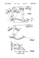
- FIG. 1 shows an elevational view of a device constructed in accordance with this invention for detecting web flutter:
- FIG. 2 shows an elevational view similar to FIG. 1 with the paper web curled in a different direction
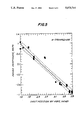
- FIG. 3 shows a graph of the web position vis-a-vis the light sensor response
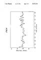
- FIGS. 4 and 5 show a typical real-time response of the probe, and the calibration curve of the probe response vs. the video data respectively.
- a device 10 constructed in accordance with this invention includes a first and second IR source 12 and 14 arranged for directing a relatively wide but thin beam of light toward a paper web 16.
- Each source may be for example an IR source generated by a light emitting diode (LED) and has a fiber optics membrane which is 1.5 inches wide by 0.05 inches thick.
- LED light emitting diode
- the web is moving in direction indicated by arrow A along a nominal paper web plane 18. (In other words, without flutter, web 16 would lie in plane 18).
- the IR sources are disposed symmetrically at an angle ⁇ /2 with respect to a line 20 normal to plane 18 as shown, angle ⁇ being the angle between the transmitters 12, 14.
- the device also includes a light point sensor 22 disposed on line 20 normal to plane 18 to sense IR light scattered from the paper web 16.
- the point sensor may be for example an IR photosensitive diode transistor made by Scientific Technology Inc. in Hayward, Calif.
- the light from the transmitters 12, 14 is highly columnated.
- the paper web has a rough surface which scatters the beams in different directions at point 24, as shown in FIG. 1 for a beam from source 12.
- some of the infrared light scattered at the point of incidence 24 between the web 16 and line 20 propagates along line 20 and is detected by the sensor 22.
- FIG. 2 As the web 16 continues to flutter it changes to the configuration shown in FIG. 2 wherein light from transmitter 14 is intercepted by sensor 22.
- light from at least one of the transmitters 12 or 14 is intercepted by the sensor 22 depending on the instantaneous position of web 18.
- the intensity of the IR light sensed by sensor 22 is inversely proportional to the distance 1 between the sensor 22 and the web 16. This distance is evaluated by feeding the output of the sensor 22 into a data processor 26.
- the device 10 can be calibrated in a number of different ways. For example, a sample may be disposed sequentially along line 20 at various distances along line 20 and the resulting sensor output may be recorded automatically by data analyzer 26 for comparison with measurements taken from a web of known movement or from a video camera.
- the data analyzer may include for example a microprocessor. A real-time tracing of flutter at sheet edge is included in FIG. 4.
- the solid continuous line indicates the response of an apparatus constructed in accordance with this invention.
- the two dotted lines disposed on either side of the solid line indicate the 95% confidence levels.
- the round bullets indicate the corresponding measurements obtained using a video camera.
- the operability of the device 10 to the aspect ratio of the web flutter is dependent on the distance L between the sensor 22 and plane 18, the width W of the beams from transmitters 12 and 14 and the angle ⁇ between the beams.
- the term aspect ratio refers to the ratio between the flutter amplitude A and the flutter wavelength V shown in FIG. 3.
- the response of sensor 22 to light scattered by web 16 is linear. This response is shown in FIG. 3 as a straight line 27, with the horizontal axis representing the distance 1 between the probe 22 and the web 16. For example if the nominal plane 18 is a distance L 1 from the sensor and the web flutters at an amplitude A 1 , the sensor generates a voltage signal V(t) approximated by
- V 1 is a dc offset voltage corresponding to the nominal position of plane 18 at distance L 1
- n is the flutter phase angle in time.
- the paper web 16 may be subjected to other motions of very low frequencies which causes the plane 18 to drift either up or down.
- the plane 18 may drift from a first distance L 1 from sensor 22 to a distance L 2 somewhat closer to the sensor. In this second position the output of sensor becomes:
- V 2 corresponds to the dc offset due to the nominal position of plane 18 at distance L 2 .
- a filter 28 is provided (as indicated in dotted line in FIG. 1) prior to the analyzer.
- the filter may be, for example, a band pass or a high pass filter designed to eliminate all signals having frequencies outside the frequency range of interest.
- the device 10 is shown in the orientation required to monitor machine-direction flutter.
- the same device may be oriented perpendicularly to direction A to thereby monitor flutter in the cross-machine direction.
Abstract
Description
V(t)=V.sub.1 +A.sub.1 sin nt ,
V(t)=V.sub.2 +A.sub.1 sin nt
Claims (17)
Priority Applications (1)
| Application Number | Priority Date | Filing Date | Title |
|---|---|---|---|
| US07/527,216 US5073714A (en) | 1990-05-22 | 1990-05-22 | Method and apparatus for detecting amplitude and frequency of web flutter using infrared optical sensor |
Applications Claiming Priority (1)
| Application Number | Priority Date | Filing Date | Title |
|---|---|---|---|
| US07/527,216 US5073714A (en) | 1990-05-22 | 1990-05-22 | Method and apparatus for detecting amplitude and frequency of web flutter using infrared optical sensor |
Publications (1)
| Publication Number | Publication Date |
|---|---|
| US5073714A true US5073714A (en) | 1991-12-17 |
Family
ID=24100580
Family Applications (1)
| Application Number | Title | Priority Date | Filing Date |
|---|---|---|---|
| US07/527,216 Expired - Fee Related US5073714A (en) | 1990-05-22 | 1990-05-22 | Method and apparatus for detecting amplitude and frequency of web flutter using infrared optical sensor |
Country Status (1)
| Country | Link |
|---|---|
| US (1) | US5073714A (en) |
Cited By (8)
| Publication number | Priority date | Publication date | Assignee | Title |
|---|---|---|---|---|
| US5712489A (en) * | 1995-11-21 | 1998-01-27 | Macmillan Bloedel Limited | Web flutter detection |
| US6004030A (en) * | 1996-11-21 | 1999-12-21 | International Business Machines Corporation | Calibration apparatus and methods for a thermal proximity sensor |
| WO2004000704A1 (en) * | 2002-06-19 | 2003-12-31 | Koenig & Bauer Aktiengesellschaft | Device for detecting a running disturbance in a running web |
| US6813941B2 (en) | 2001-12-20 | 2004-11-09 | Kimberly-Clark Worldwide, Inc. | Method to measure tension in a moving web and to control properties of the web |
| US20060122515A1 (en) * | 2000-01-19 | 2006-06-08 | Luminetx Corporation | Projection of subsurface structure onto an object's surface |
| US7239909B2 (en) | 2000-01-19 | 2007-07-03 | Luminetx Technologies Corp. | Imaging system using diffuse infrared light |
| WO2009123676A1 (en) * | 2008-04-02 | 2009-10-08 | Eastman Kodak Company | Distance and orientation measurement of an object |
| US20120031577A1 (en) * | 2007-11-19 | 2012-02-09 | Banks Rodney H | Fluorometric method for monitoring surface additives in a papermaking process |
Citations (6)
| Publication number | Priority date | Publication date | Assignee | Title |
|---|---|---|---|---|
| US3703097A (en) * | 1970-12-24 | 1972-11-21 | Kaiser Aluminium Chem Corp | Method and system for measuring sheet flatness |
| US3892492A (en) * | 1972-10-16 | 1975-07-01 | Loepfe Ag Geb | Optoelectrical apparatus with directional light sources for detecting reflection behaviour of an object |
| US3906232A (en) * | 1973-10-31 | 1975-09-16 | Butler Automatic Inc | Web break detector |
| US4276910A (en) * | 1979-03-15 | 1981-07-07 | Gebruder Loepfe Ag | Photoelectrical bobbin feeler |
| US4501642A (en) * | 1982-09-23 | 1985-02-26 | Champion International Corporation | Method of paper tension control to maintain flutter within a predetermined range |
| US4637727A (en) * | 1982-12-09 | 1987-01-20 | Raimo Ahola | Procedure for analyzing reciprocating motion |
-
1990
- 1990-05-22 US US07/527,216 patent/US5073714A/en not_active Expired - Fee Related
Patent Citations (6)
| Publication number | Priority date | Publication date | Assignee | Title |
|---|---|---|---|---|
| US3703097A (en) * | 1970-12-24 | 1972-11-21 | Kaiser Aluminium Chem Corp | Method and system for measuring sheet flatness |
| US3892492A (en) * | 1972-10-16 | 1975-07-01 | Loepfe Ag Geb | Optoelectrical apparatus with directional light sources for detecting reflection behaviour of an object |
| US3906232A (en) * | 1973-10-31 | 1975-09-16 | Butler Automatic Inc | Web break detector |
| US4276910A (en) * | 1979-03-15 | 1981-07-07 | Gebruder Loepfe Ag | Photoelectrical bobbin feeler |
| US4501642A (en) * | 1982-09-23 | 1985-02-26 | Champion International Corporation | Method of paper tension control to maintain flutter within a predetermined range |
| US4637727A (en) * | 1982-12-09 | 1987-01-20 | Raimo Ahola | Procedure for analyzing reciprocating motion |
Cited By (12)
| Publication number | Priority date | Publication date | Assignee | Title |
|---|---|---|---|---|
| US5712489A (en) * | 1995-11-21 | 1998-01-27 | Macmillan Bloedel Limited | Web flutter detection |
| US6004030A (en) * | 1996-11-21 | 1999-12-21 | International Business Machines Corporation | Calibration apparatus and methods for a thermal proximity sensor |
| US20060122515A1 (en) * | 2000-01-19 | 2006-06-08 | Luminetx Corporation | Projection of subsurface structure onto an object's surface |
| US7239909B2 (en) | 2000-01-19 | 2007-07-03 | Luminetx Technologies Corp. | Imaging system using diffuse infrared light |
| US8078263B2 (en) | 2000-01-19 | 2011-12-13 | Christie Medical Holdings, Inc. | Projection of subsurface structure onto an object's surface |
| US6813941B2 (en) | 2001-12-20 | 2004-11-09 | Kimberly-Clark Worldwide, Inc. | Method to measure tension in a moving web and to control properties of the web |
| US20050034831A1 (en) * | 2001-12-20 | 2005-02-17 | Beuther Paul D. | Method to measure tension in a moving web and to control properties of the web |
| WO2004000704A1 (en) * | 2002-06-19 | 2003-12-31 | Koenig & Bauer Aktiengesellschaft | Device for detecting a running disturbance in a running web |
| US20120031577A1 (en) * | 2007-11-19 | 2012-02-09 | Banks Rodney H | Fluorometric method for monitoring surface additives in a papermaking process |
| US8480856B2 (en) * | 2007-11-19 | 2013-07-09 | Nalco Company | Fluorometric method for monitoring surface additives in a papermaking process |
| WO2009123676A1 (en) * | 2008-04-02 | 2009-10-08 | Eastman Kodak Company | Distance and orientation measurement of an object |
| CN101981468B (en) * | 2008-04-02 | 2013-03-27 | 伊斯曼柯达公司 | Distance and orientation measurement of an object |
Similar Documents
| Publication | Publication Date | Title |
|---|---|---|
| US4966455A (en) | Real time mottle measuring device and method | |
| US4955720A (en) | On-line fiber orientation distribution measurement | |
| US4182259A (en) | Apparatus for measuring coating thickness on an applicator roll | |
| US5341824A (en) | Method and apparatus for inspecting and controlling tipping paper perforation | |
| US4931657A (en) | On-line texture sensing | |
| KR890015660A (en) | Compensation system to inspect potentially warped printed circuit boards | |
| US5073714A (en) | Method and apparatus for detecting amplitude and frequency of web flutter using infrared optical sensor | |
| KR860004303A (en) | Method of measuring average cross-sectional properties of yarn or filament by light scattering analysis | |
| US4760271A (en) | Apparatus and process for measuring formation and roughness of a paper web | |
| US4570074A (en) | Flying spot scanner system | |
| EP0612977B1 (en) | Method and apparatus for determining the fiber orientation of paper | |
| US4070575A (en) | Measurement of flow of particulate material by sensing the shadow profile | |
| US20060054843A1 (en) | Method and apparatus of improving optical reflection images of a laser on a changing surface location | |
| US3803414A (en) | Standardization of infrared measuring system | |
| US5066865A (en) | Single sided reflectance sensor for measuring select physical properties of a material using one or more wavelengths of radiation | |
| US7224447B2 (en) | System and method for measuring the permeability of a material | |
| US4252443A (en) | Blackening sensor | |
| US6067162A (en) | Process for measuring the roughness of a material surface | |
| WO2000031521A1 (en) | Non-scanning, on-line multiple wavelength sheet monitoring system | |
| CA2481674A1 (en) | Method for determining the scale of an observation area | |
| JP2004163129A (en) | Defect inspection method | |
| JP2873450B2 (en) | Defect inspection device using light | |
| JPH1062146A (en) | Defect examining device of sheet-shaped object | |
| JPH02114146A (en) | Method and device for measuring crack length and strain in structure part and test piece | |
| US4968386A (en) | Apparatus for determining amplitude and frequency of web flutter |
Legal Events
| Date | Code | Title | Description |
|---|---|---|---|
| AS | Assignment |
Owner name: UNION CAMP CORPORATION, A CORP. OF VA. Free format text: ASSIGNMENT OF ASSIGNORS INTEREST.;ASSIGNOR:NGUYEN, DONG D.;REEL/FRAME:005322/0560 Effective date: 19900511 |
|
| FPAY | Fee payment |
Year of fee payment: 4 |
|
| FEPP | Fee payment procedure |
Free format text: PAYOR NUMBER ASSIGNED (ORIGINAL EVENT CODE: ASPN); ENTITY STATUS OF PATENT OWNER: LARGE ENTITY |
|
| REMI | Maintenance fee reminder mailed | ||
| LAPS | Lapse for failure to pay maintenance fees | ||
| FP | Lapsed due to failure to pay maintenance fee |
Effective date: 19991217 |
|
| FEPP | Fee payment procedure |
Free format text: PAYER NUMBER DE-ASSIGNED (ORIGINAL EVENT CODE: RMPN); ENTITY STATUS OF PATENT OWNER: LARGE ENTITY Free format text: PAYOR NUMBER ASSIGNED (ORIGINAL EVENT CODE: ASPN); ENTITY STATUS OF PATENT OWNER: LARGE ENTITY |
|
| AS | Assignment |
Owner name: INTERNATIONAL PAPER COMPANY, CONNECTICUT Free format text: MERGER;ASSIGNOR:UNION CAMP CORPORATION;REEL/FRAME:013758/0077 Effective date: 19990430 |
|
| STCH | Information on status: patent discontinuation |
Free format text: PATENT EXPIRED DUE TO NONPAYMENT OF MAINTENANCE FEES UNDER 37 CFR 1.362 |