US5060695A - Bypass flow pressure regulator - Google Patents
Bypass flow pressure regulator Download PDFInfo
- Publication number
- US5060695A US5060695A US07/502,897 US50289790A US5060695A US 5060695 A US5060695 A US 5060695A US 50289790 A US50289790 A US 50289790A US 5060695 A US5060695 A US 5060695A
- Authority
- US
- United States
- Prior art keywords
- fluid
- armature
- pressure regulating
- assembly according
- regulating assembly
- Prior art date
- Legal status (The legal status is an assumption and is not a legal conclusion. Google has not performed a legal analysis and makes no representation as to the accuracy of the status listed.)
- Expired - Lifetime
Links
Images


Classifications
-
- G—PHYSICS
- G05—CONTROLLING; REGULATING
- G05D—SYSTEMS FOR CONTROLLING OR REGULATING NON-ELECTRIC VARIABLES
- G05D16/00—Control of fluid pressure
- G05D16/20—Control of fluid pressure characterised by the use of electric means
- G05D16/2006—Control of fluid pressure characterised by the use of electric means with direct action of electric energy on controlling means
- G05D16/2013—Control of fluid pressure characterised by the use of electric means with direct action of electric energy on controlling means using throttling means as controlling means
- G05D16/2024—Control of fluid pressure characterised by the use of electric means with direct action of electric energy on controlling means using throttling means as controlling means the throttling means being a multiple-way valve
-
- G—PHYSICS
- G05—CONTROLLING; REGULATING
- G05D—SYSTEMS FOR CONTROLLING OR REGULATING NON-ELECTRIC VARIABLES
- G05D16/00—Control of fluid pressure
- G05D16/20—Control of fluid pressure characterised by the use of electric means
- G05D16/2093—Control of fluid pressure characterised by the use of electric means with combination of electric and non-electric auxiliary power
- G05D16/2097—Control of fluid pressure characterised by the use of electric means with combination of electric and non-electric auxiliary power using pistons within the main valve
-
- Y—GENERAL TAGGING OF NEW TECHNOLOGICAL DEVELOPMENTS; GENERAL TAGGING OF CROSS-SECTIONAL TECHNOLOGIES SPANNING OVER SEVERAL SECTIONS OF THE IPC; TECHNICAL SUBJECTS COVERED BY FORMER USPC CROSS-REFERENCE ART COLLECTIONS [XRACs] AND DIGESTS
- Y10—TECHNICAL SUBJECTS COVERED BY FORMER USPC
- Y10T—TECHNICAL SUBJECTS COVERED BY FORMER US CLASSIFICATION
- Y10T137/00—Fluid handling
- Y10T137/8593—Systems
- Y10T137/86493—Multi-way valve unit
- Y10T137/86574—Supply and exhaust
- Y10T137/86582—Pilot-actuated
- Y10T137/8659—Variable orifice-type modulator
-
- Y—GENERAL TAGGING OF NEW TECHNOLOGICAL DEVELOPMENTS; GENERAL TAGGING OF CROSS-SECTIONAL TECHNOLOGIES SPANNING OVER SEVERAL SECTIONS OF THE IPC; TECHNICAL SUBJECTS COVERED BY FORMER USPC CROSS-REFERENCE ART COLLECTIONS [XRACs] AND DIGESTS
- Y10—TECHNICAL SUBJECTS COVERED BY FORMER USPC
- Y10T—TECHNICAL SUBJECTS COVERED BY FORMER US CLASSIFICATION
- Y10T137/00—Fluid handling
- Y10T137/8593—Systems
- Y10T137/86493—Multi-way valve unit
- Y10T137/86574—Supply and exhaust
- Y10T137/86582—Pilot-actuated
- Y10T137/86614—Electric
-
- Y—GENERAL TAGGING OF NEW TECHNOLOGICAL DEVELOPMENTS; GENERAL TAGGING OF CROSS-SECTIONAL TECHNOLOGIES SPANNING OVER SEVERAL SECTIONS OF THE IPC; TECHNICAL SUBJECTS COVERED BY FORMER USPC CROSS-REFERENCE ART COLLECTIONS [XRACs] AND DIGESTS
- Y10—TECHNICAL SUBJECTS COVERED BY FORMER USPC
- Y10T—TECHNICAL SUBJECTS COVERED BY FORMER US CLASSIFICATION
- Y10T137/00—Fluid handling
- Y10T137/8593—Systems
- Y10T137/86493—Multi-way valve unit
- Y10T137/86574—Supply and exhaust
- Y10T137/86622—Motor-operated
Definitions
- the present invention relates to fluid pressure regulators, and more particularly to a pressure regulator for regulating the fluid pressure in the transmission of an automotive vehicle.
- a typical pressure control device may include a housing encasing a magnetic coil and an armature control slide movable within a valve through which a pressure medium to be controlled passes.
- a main object of the invention is to provide a pressure control device that overcomes problems, such as those referred to above, exhibited by prior art devices.
- the spool valve is not connected to the armature. Instead, the armature operates a first stage poppet servo valve.
- servo pressure is determined by the force balance on the armature, and the resulting servo pressure force has to equal the sum of the magnetic force and a mechanical spring force.
- Hydraulic flow forces do not enter into the armature force balance and therefore do not have a large effect on the regulation of the device.
- a pressure regulating device for regulating the pressure of a flowing medium includes means forming a housing.
- a stationary member and moveable armature are disposed within the housing, and a coil means disposed about the stationary member and the armature receives current for generating magnetic flux to create an attractive force to move the armature in relation to the stationary member.
- At least one aperture is formed in the housing to allow a fluid medium to enter and exit the housing.
- a means is disposed in the housing for bleeding a portion of the fluid medium based on the current to the coil means to control the output pressure to predetermined pressure levels.
- the subject invention provides a means for bleeding some of the pressure of the fluid medium to reduce the output pressure of the pressure regulating device to various predetermined pressure levels.
- FIG. 1 is a cross sectional elevational view of a single-stage embodiment of the present invention
- FIG. 2 is a cross sectional elevational view of a two-stage embodiment of the present invention
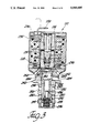
- FIG. 3 is a cross sectional elevational view of an alternate two-stage embodiment of the present invention.
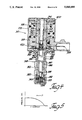
- FIG. 4 is a cross sectional elevational view of a second alternative two-stage embodiment of the present invention.
- FIG. 5 is a qualitative curve illustrating the output pressure/current performance of the FIG. 1 embodiment.
- a pressure regulating device for regulating the pressure of a flowing fluid medium is generally shown at 10 in FIG. 1.
- the device 10 includes a stationary generally cylindrical pole piece or member 12 having axially opposed ends 14 and 16.
- the stationary member 12 also includes a passageway 18 communicating axially therethrough.
- the device 10 also includes a movable armature means disposed axially from the stationary member 12 for movement axially in relation to the stationary member 12.
- the armature means comprises a cylindrical shaped armature 20 having an open end 22 spaced axially from the end 14 of the stationary member 12. This creates a working gap 23 between the armature 20 and the end 14 of the stationary member 12.
- the working gap 23 defines the distance the armature 20 moves in relation to the stationary member 12.
- the armature 20 also includes a closed end 24 axially opposite the first end 22.
- the device 10 further includes a coil means disposed partially about the stationary member 12 and the armature 20 and through which an electrical current flows from a source (not shown) for generating magnetic flux to create an attractive force to move the armature 20 in relation to the stationary member 12.
- the coil means comprises a solenoid coil 26.
- the current flowing through the solenoid coil 26 may be DC or the average value resulting from a chopped or pulse width modulated electrical supply.
- the attractive force is proportional to the current and the square of the number of turns of wire on the solenoid coil 26 and inversely proportional to the square of the distance 23 between armature 20 and the end 14 of the stationary member 12.
- An annular U-shaped bracket member 28 is disposed partially about the stationary member 12 and armature 20, and the solenoid coil 26 is disposed within the bracket member 28, which forms a central passage 30 communicating axially through it.
- the armature 20 is slidably disposed in the passage 30 while the stationary member 12 is press-fitted into one end of the passage 30.
- a pair of connectors 32 are disposed in bores 34 formed in the bracket member 28 and connected to the solenoid coil 26 for attachment to an electrical supply source to allow electrical current to flow to the solenoid coil 26.
- a return member 36 is threadably engaged and disposed about one end of the stationary member 12 and abuts one end of the bracket member 28.
- the return member 36 creates a closed flux loop by allowing magnetic flux to flow from the solenoid coil 26 through the bracket member 28 and return member 36 to the stationary member 12 and across the working gap 23 to the armature 20 back to the solenoid coil 26.
- the device 10 includes a housing means encasing the armature 20, solenoid coil 26 and stationary member 12.
- the housing means comprises an annular casing 38 about the device 10 to prevent undesired or foreign contaminants from entering the device 10, and it also includes a pair of annular seals 40 and 41 at one end of the bracket member 28 to prevent fluid contaminants from contacting the solenoid coil 26.
- the device 10 further includes a valve housing, generally indicated at 42, with apertures formed therein to allow a fluid medium to enter and exit the valve housing 42 and to contact the armature 20.
- valve housing 42 has at least first aperture or cavity 44 formed therein to allow the fluid medium to enter and at least one second aperture or cavity 46 formed therein communicating via restriction means with the first aperture 44 to allow the fluid medium to exit the valve housing 42.
- the valve housing 42 further has at least one aperture or cavity 48, formed therein and communicating with at least one of the second apertures 46, to allow the fluid medium to flow to a first internal passage 50 in the valve housing 42.
- the first internal passage 50 allows such fluid medium as flows from conduit or inlet means 44, through restriction means 45, passage means 46 and depicted diagonally disposed passage means 48, to, generally, the armature 20.
- the valve housing 42 further includes at least one second internal chamber and means passage 52 communicating with the first internal passage 50 to thereby allow the fluid medium to flow from the first internal passage 50 to the sump (not shown) and bypass the fluid output of the device 10.
- the device 10 further includes a bleed valve means spaced axially from one end and connected to the armature 20 for moving in unseen with the armature 20.
- the bleed valve means comprises a valve plate 54 having one end 56 threadably engaging an aperture 58 formed in the closed end 24 of the armature 20.
- the valve plate 54 has an axially spaced end 60 which operatively cooperates with the valve seat 61 of housing 42 to allow or block fluid flow through the first internal chamber and passage means 50 to the second internal passage 52.
- the valve plate 54 also includes an aperture 62 to allow a small predetermined amount of fluid to enter the cavity 64 of the armature 20.
- the device 10 includes a biasing means for continuously biasing the valve plate 54 toward the valve housing 42.
- the biasing means comprises a spring 66 disposed within the cavity 64, formed in the armature 20, between an adjustment means 68 and the closed end 24 of the armature 20.
- the spring adjustment means 68 is disposed axially within the cavity 64 of the armature for controlling the force of the spring 66 on the armature 20 in relation to the face of the valve housing 42, and it comprises a threaded rod 68 threadably engageable with the stationary member or pole piece means 12 and having one end 70 disposed within the cavity 64 of the armature 20.
- the device 10 controls output pressure in response to an electrical current by bypassing fluid flow from its inlet aperture 44 and second internal chamber and passage means 52 back to its sump (not shown).
- the device 10 receives electrical current from a power source through the connectors 32 leading to the solenoid coil 26.
- the solenoid coil 26 generates magnetic flux to create an attractive force between the armature 20 and the stationary member or pole piece means 12.
- the armature 20 moves toward the stationary member 12 it moves the valve plate 54 away from the face of the valve housing 42 and away from cooperating valve seat 61 to open the flow path from the first internal passage 50, which is in effect receiving inlet pressure, to the second internal chamber and passage means 52, thereby bypassing fluid flow to the sump.
- This decreases the fluid flow and output pressure through aperture 46.
- the output pressure will increase or decrease in relation to the amount of current t the solenoid coil 26.
- the spring 66 applies a force to bias the valve plate 54 toward the face of the valve seat 61, opposing the primary balancing force due to pressure on the valve plate 54, such that a predetermined amount of current is required in the solenoid coil 26 to move the valve plate 54 and armature 20 away from valve seat.
- Adjustment of the spring 66 can be accomplished by rotating the rod 68 and moving it axially to set the bypass pressure for a predetermined current level.
- the output pressure varies with the current (qualitatively as shown in FIG. 5) such that, for example, at zero amperes of current, the output pressure is 100 psi, and at 1.0 ampere of current, the output pressure is zero psi.
- the output pressure-to-current performance may be varied by design.
- a two-stage embodiment of the present invention is generally shown at 110 in FIG. 2, wherein elements or details which are like or similar to those of the FIG. 1 embodiment have like reference numerals increased by 100 (one hundred).
- the embodiment 110 is generally similar in construction to the single-stage embodiment 10 of FIG. 1.
- the stationary member or pole piece means 112 and armature 120 are similar to those of the embodiment 10.
- the device 110 further includes a valve housing, generally indicated at 142, having one or more apertures in the valve housing 142 to allow a fluid medium to enter and exit the valve housing 142, as well as exit in the vicinity of the armature 120.
- a first aperture 180 is formed in the valve housing 142 to allow the fluid medium to enter the valve housing 142.
- Second aperture means 182 formed in the valve housing 142 allows the fluid medium to exit the valve housing 142.
- Third aperture means 184 is formed in the valve housing 142 to allow fluid to exit the valve housing 142 and flow back to the sump (not shown).
- the device 110 further includes a flow valve means moving independently of the armature 120.
- the flow valve means is similar to that disclosed in copending application, U.S. Ser. No. 07/066,693, entitled “Transmission Pressure Regulator” of Ralph P. McCabe, which is hereby incorporated herein by reference.
- the flow valve means comprises a spool valve 186 having a first end 188 spaced axially from the closed end 124 of the armature 120.
- the first end 188 of the spool valve 186 includes a first cavity 189 formed therein.
- the spool valve 186 also includes a first internal passage 190 communicating with the first aperture 180 of the valve housing 142 via flow restriction means 145, and the first cavity 189 of the first end 188 to allow the fluid medium to flow from the first aperture 180 to the first cavity 189.
- the spool valve 186 also includes a second end 192 axially opposite the first end 188 and having a second cavity 193 formed therein.
- the spool valve 186 also includes an annular recessed portion 194 about the circumference thereof between the first end 188 and the second end 192 thereof.
- the spool valve 186 also includes a third internal passage 195 communicating with the annular recessed portion 194 and the second cavity 193 to control or move the spool valve 186 independently of the armature 120.
- a spring 196 may be disposed in the second cavity 193 to bias the spool valve 186 toward the armature 120 to reduce osciliations of the spool valve 186 due to fluid flow.
- the operation of the spool valve 186 is similar to that of spool valve 50 disclosed in the above-mentioned copending application while the operation of the bleed valve means 154 is similar to the FIG. 1 embodiment bleed valve means designated by the reference numeral 54.
- a first alternate two-stage embodiment of the present invention is shown at 210 in FIG. 3.
- the elements and/or detected FIG. 3 which are like or similar to either those of FIG. 1 or FIG. 2 embodiments are identified with similar reference numbers (the last two digits being the same as the two-digit reference numbers in FIG. 1 or the same as the last two digits in the reference numbers of FIG. 2).
- the second alternate embodiment 210 is similar in construction to embodiment 110 of FIG. 2.
- the device 210 has the second internal passage 252 shown as extending diagonally outwardly of the valve housing 242 relative to the first internal passage 290.
- the device 210 includes a flux return washer 298 and eliminates the connectors 32 of the device 10 and substitutes a terminal 299 leading from the coil 226.
- the operation of the device 210 is the same as that of the device 110.
- FIG. 4 illustrates a second alternate two-stage embodiment 310 of the device 110, like parts of the FIG. 2 and FIG. 3 first alternate two-stage embodiment again being identified with similar reference numerals.
- the device 310 includes a pole washer 400 at one end of the bracket member 328 and a flux return washer 402 at the other end of the bracket member 328.
- the device 310 also includes a valve seat 404 disposed within the valve housing 342 with which the valve plate 354 cooperates. Again, the operation of the device 310 is generally the same as that of the device 110.
Abstract
Description
Claims (32)
Priority Applications (5)
| Application Number | Priority Date | Filing Date | Title |
|---|---|---|---|
| US07/502,897 US5060695A (en) | 1990-04-02 | 1990-04-02 | Bypass flow pressure regulator |
| EP90123405A EP0451347B1 (en) | 1990-04-02 | 1990-12-06 | Bypass flow pressure regulator |
| DE69021372T DE69021372T2 (en) | 1990-04-02 | 1990-12-06 | Pressure regulator for bypass flow. |
| CA002031946A CA2031946C (en) | 1990-04-02 | 1990-12-11 | Bypass flow pressure regulator |
| JP02414594A JP3115331B2 (en) | 1990-04-02 | 1990-12-26 | Pressure regulator |
Applications Claiming Priority (1)
| Application Number | Priority Date | Filing Date | Title |
|---|---|---|---|
| US07/502,897 US5060695A (en) | 1990-04-02 | 1990-04-02 | Bypass flow pressure regulator |
Publications (1)
| Publication Number | Publication Date |
|---|---|
| US5060695A true US5060695A (en) | 1991-10-29 |
Family
ID=23999857
Family Applications (1)
| Application Number | Title | Priority Date | Filing Date |
|---|---|---|---|
| US07/502,897 Expired - Lifetime US5060695A (en) | 1990-04-02 | 1990-04-02 | Bypass flow pressure regulator |
Country Status (5)
| Country | Link |
|---|---|
| US (1) | US5060695A (en) |
| EP (1) | EP0451347B1 (en) |
| JP (1) | JP3115331B2 (en) |
| CA (1) | CA2031946C (en) |
| DE (1) | DE69021372T2 (en) |
Cited By (30)
| Publication number | Priority date | Publication date | Assignee | Title |
|---|---|---|---|---|
| US5121769A (en) * | 1991-05-30 | 1992-06-16 | Coltec Industries Inc. | Solenoid operated pressure regulating valve |
| US5184644A (en) * | 1991-05-30 | 1993-02-09 | Coltec Industries Inc. | Solenoid operated pressure regulating valve |
| US5217047A (en) * | 1991-05-30 | 1993-06-08 | Coltec Industries Inc. | Solenoid operated pressure regulating valve |
| US5240227A (en) * | 1990-01-20 | 1993-08-31 | Robert Bosch Gmbh | Electromagnetically operated valve |
| US5611370A (en) * | 1994-11-10 | 1997-03-18 | Saturn Electronics & Engineering, Inc. | Proportional variable force solenoid control valve and transmission fluid control device |
| US5722459A (en) * | 1995-05-31 | 1998-03-03 | Hyundai Motor Company | Pressure control valve of a hydraulic control system of an automatic transmission |
| US5757259A (en) * | 1994-07-28 | 1998-05-26 | Caterpillar Inc. | Anti-rotation device for joining a shell and encapsulated terminal/coil subassembly |
| US5845667A (en) * | 1996-12-19 | 1998-12-08 | Saturn Electronics & Engineering, Inc. | Single stage variable force solenoid pressure regulating valve |
| US5984259A (en) * | 1997-11-26 | 1999-11-16 | Saturn Electronics & Engineering, Inc. | Proportional variable force solenoid control valve with armature damping |
| US5996628A (en) * | 1996-01-16 | 1999-12-07 | Saturn Electronics & Engineering, Inc. | Proportional variable force solenoid control valve |
| US6019120A (en) * | 1996-12-19 | 2000-02-01 | Saturn Electronics & Engineering, Inc. | Single stage variable force solenoid pressure regulating valve |
| US20040089353A1 (en) * | 2002-11-12 | 2004-05-13 | Mitsubishi Denki Kabushiki Kaisha | Electromagnetic valve |
| US20050138890A1 (en) * | 2003-03-13 | 2005-06-30 | Charles Starke | Continuous structural wall system |
| WO2014058490A1 (en) | 2012-10-08 | 2014-04-17 | Automatic Switch Company | Method and apparatus for bias member adjustment without disassembly |
| CN103883778A (en) * | 2012-12-21 | 2014-06-25 | Mac阀门有限公司 | Multi-port modular valve with snap-in seat |
| US10473229B2 (en) | 2017-09-25 | 2019-11-12 | Mac Valves, Inc. | Diaphragm valve |
| US20220003332A1 (en) * | 2018-11-13 | 2022-01-06 | Walbro Llc | Electromechanical valve and method of assembly |
| US11225962B2 (en) * | 2018-05-23 | 2022-01-18 | Eagle Industry Co., Ltd. | Capacity control valve |
| US11391388B2 (en) | 2018-12-04 | 2022-07-19 | Eagle Industry Co., Ltd. | Capacity control valve |
| US11434885B2 (en) | 2017-12-27 | 2022-09-06 | Eagle Industry Co., Ltd. | Capacity control valve and method for controlling same |
| US11454227B2 (en) | 2018-01-22 | 2022-09-27 | Eagle Industry Co., Ltd. | Capacity control valve |
| US11486376B2 (en) | 2017-12-27 | 2022-11-01 | Eagle Industry Co., Ltd. | Capacity control valve and method for controlling same |
| US11512786B2 (en) * | 2017-11-30 | 2022-11-29 | Eagle Industry Co., Ltd. | Capacity control valve and control method for capacity control valve |
| US11519399B2 (en) | 2017-12-08 | 2022-12-06 | Eagle Industry Co., Ltd. | Capacity control valve and method for controlling same |
| US11542931B2 (en) | 2017-11-15 | 2023-01-03 | Eagle Industry Co., Ltd. | Capacity control valve and capacity control valve control method |
| US11542929B2 (en) | 2017-12-14 | 2023-01-03 | Eagle Industry Co., Ltd. | Capacity control valve and method for controlling capacity control valve |
| US11542930B2 (en) | 2017-02-18 | 2023-01-03 | Eagle Industry Co., Ltd. | Capacity control valve |
| US11603832B2 (en) | 2017-01-26 | 2023-03-14 | Eagle Industry Co., Ltd. | Capacity control valve having a throttle valve portion with a communication hole |
| US11635152B2 (en) | 2018-11-26 | 2023-04-25 | Eagle Industry Co., Ltd. | Capacity control valve |
| US11802552B2 (en) | 2019-07-12 | 2023-10-31 | Eagle Industry Co., Ltd. | Capacity control valve |
Families Citing this family (2)
| Publication number | Priority date | Publication date | Assignee | Title |
|---|---|---|---|---|
| US6404314B1 (en) * | 2000-02-29 | 2002-06-11 | General Electric Company | Adjustable trip solenoid |
| DE10150238C2 (en) * | 2001-10-11 | 2003-09-25 | Hydac Fluidtechnik Gmbh | Pressure regulating valve, in particular proportional pressure regulating valve |
Citations (6)
| Publication number | Priority date | Publication date | Assignee | Title |
|---|---|---|---|---|
| FR1100189A (en) * | 1953-03-31 | 1955-09-16 | Asea Ab | Pressure regulator shutter |
| US2896588A (en) * | 1956-04-04 | 1959-07-28 | Sanders Associates Inc | Electro-hydraulic servo valve |
| US3789735A (en) * | 1973-02-15 | 1974-02-05 | Bendix Corp | Diverter valve means for pressure differentially operated servomotor |
| US3856047A (en) * | 1971-12-02 | 1974-12-24 | Aisin Seiki | Pressure control valve |
| US4538643A (en) * | 1982-06-11 | 1985-09-03 | Kienzle Apparate Gmbh | Electropneumatic pilot control stage for a pneumatic servo valve |
| US4674613A (en) * | 1985-12-16 | 1987-06-23 | Controlled Hydraulics, Inc. | Electrically controlled transmission soft shifter |
Family Cites Families (4)
| Publication number | Priority date | Publication date | Assignee | Title |
|---|---|---|---|---|
| US3073345A (en) * | 1961-05-01 | 1963-01-15 | Gen Motors Corp | Solenoid operated vacuum regulator |
| DE2133433A1 (en) * | 1971-07-05 | 1973-01-18 | Bosch Gmbh Robert | ELECTROMAGNETIC PRESSURE REGULATING VALVE |
| DE3038797A1 (en) * | 1980-10-14 | 1982-05-27 | Herion-Werke Kg, 7012 Fellbach | PRESSURE CONTROL VALVE |
| DE8322570U1 (en) * | 1983-08-05 | 1985-01-17 | Robert Bosch Gmbh, 7000 Stuttgart | PRESSURE REGULATOR |
-
1990
- 1990-04-02 US US07/502,897 patent/US5060695A/en not_active Expired - Lifetime
- 1990-12-06 DE DE69021372T patent/DE69021372T2/en not_active Expired - Fee Related
- 1990-12-06 EP EP90123405A patent/EP0451347B1/en not_active Expired - Lifetime
- 1990-12-11 CA CA002031946A patent/CA2031946C/en not_active Expired - Lifetime
- 1990-12-26 JP JP02414594A patent/JP3115331B2/en not_active Expired - Fee Related
Patent Citations (6)
| Publication number | Priority date | Publication date | Assignee | Title |
|---|---|---|---|---|
| FR1100189A (en) * | 1953-03-31 | 1955-09-16 | Asea Ab | Pressure regulator shutter |
| US2896588A (en) * | 1956-04-04 | 1959-07-28 | Sanders Associates Inc | Electro-hydraulic servo valve |
| US3856047A (en) * | 1971-12-02 | 1974-12-24 | Aisin Seiki | Pressure control valve |
| US3789735A (en) * | 1973-02-15 | 1974-02-05 | Bendix Corp | Diverter valve means for pressure differentially operated servomotor |
| US4538643A (en) * | 1982-06-11 | 1985-09-03 | Kienzle Apparate Gmbh | Electropneumatic pilot control stage for a pneumatic servo valve |
| US4674613A (en) * | 1985-12-16 | 1987-06-23 | Controlled Hydraulics, Inc. | Electrically controlled transmission soft shifter |
Cited By (42)
| Publication number | Priority date | Publication date | Assignee | Title |
|---|---|---|---|---|
| US5240227A (en) * | 1990-01-20 | 1993-08-31 | Robert Bosch Gmbh | Electromagnetically operated valve |
| US5184644A (en) * | 1991-05-30 | 1993-02-09 | Coltec Industries Inc. | Solenoid operated pressure regulating valve |
| US5217047A (en) * | 1991-05-30 | 1993-06-08 | Coltec Industries Inc. | Solenoid operated pressure regulating valve |
| US5282604A (en) * | 1991-05-30 | 1994-02-01 | Coltec Industries Inc. | Solenoid operated pressure regulating valve |
| US5121769A (en) * | 1991-05-30 | 1992-06-16 | Coltec Industries Inc. | Solenoid operated pressure regulating valve |
| US5757259A (en) * | 1994-07-28 | 1998-05-26 | Caterpillar Inc. | Anti-rotation device for joining a shell and encapsulated terminal/coil subassembly |
| US5921526A (en) * | 1994-11-10 | 1999-07-13 | Saturn Electronics & Engineering, Inc. | Proportional variable force solenoid control valve and transmission fluid control device |
| US6109300A (en) * | 1994-11-10 | 2000-08-29 | Saturn Electronics & Engineering, Inc. | Proportional variable force solenoid control valve and transmission fluid control device |
| US5611370A (en) * | 1994-11-10 | 1997-03-18 | Saturn Electronics & Engineering, Inc. | Proportional variable force solenoid control valve and transmission fluid control device |
| US5722459A (en) * | 1995-05-31 | 1998-03-03 | Hyundai Motor Company | Pressure control valve of a hydraulic control system of an automatic transmission |
| US5996628A (en) * | 1996-01-16 | 1999-12-07 | Saturn Electronics & Engineering, Inc. | Proportional variable force solenoid control valve |
| US5845667A (en) * | 1996-12-19 | 1998-12-08 | Saturn Electronics & Engineering, Inc. | Single stage variable force solenoid pressure regulating valve |
| US6019120A (en) * | 1996-12-19 | 2000-02-01 | Saturn Electronics & Engineering, Inc. | Single stage variable force solenoid pressure regulating valve |
| US5984259A (en) * | 1997-11-26 | 1999-11-16 | Saturn Electronics & Engineering, Inc. | Proportional variable force solenoid control valve with armature damping |
| US6223761B1 (en) | 1997-11-26 | 2001-05-01 | Saturn Electronics & Engineering, Inc. | Proportional variable force solenoid control valve with armature damping |
| US6435472B1 (en) | 1997-11-26 | 2002-08-20 | Saturn Electronics & Engineering, Inc. | Proportional variable force solenoid control valve with armature damping |
| US20040089353A1 (en) * | 2002-11-12 | 2004-05-13 | Mitsubishi Denki Kabushiki Kaisha | Electromagnetic valve |
| US7017601B2 (en) * | 2002-11-12 | 2006-03-28 | Mitsubishi Denki Kabushiki Kaisha | Electromagnetic valve |
| US20050138890A1 (en) * | 2003-03-13 | 2005-06-30 | Charles Starke | Continuous structural wall system |
| WO2014058490A1 (en) | 2012-10-08 | 2014-04-17 | Automatic Switch Company | Method and apparatus for bias member adjustment without disassembly |
| CN103883778A (en) * | 2012-12-21 | 2014-06-25 | Mac阀门有限公司 | Multi-port modular valve with snap-in seat |
| US20140332093A1 (en) * | 2012-12-21 | 2014-11-13 | Mac Valves, Inc. | Multi-port modular valve with snap-in seat |
| US9395010B2 (en) * | 2012-12-21 | 2016-07-19 | Mac Valves, Inc. | Multi-port modular valve with snap-in seat |
| CN103883778B (en) * | 2012-12-21 | 2017-07-28 | Mac阀门有限公司 | Multi-port modular valve with buckle base |
| US8783653B2 (en) * | 2012-12-21 | 2014-07-22 | Mac Valves, Inc. | Multi-port modular valve with snap-in seat |
| US11603832B2 (en) | 2017-01-26 | 2023-03-14 | Eagle Industry Co., Ltd. | Capacity control valve having a throttle valve portion with a communication hole |
| US11542930B2 (en) | 2017-02-18 | 2023-01-03 | Eagle Industry Co., Ltd. | Capacity control valve |
| US10473229B2 (en) | 2017-09-25 | 2019-11-12 | Mac Valves, Inc. | Diaphragm valve |
| US11795928B2 (en) | 2017-11-15 | 2023-10-24 | Eagle Industry Co., Ltd. | Capacity control valve and capacity control valve control method |
| US11542931B2 (en) | 2017-11-15 | 2023-01-03 | Eagle Industry Co., Ltd. | Capacity control valve and capacity control valve control method |
| US11512786B2 (en) * | 2017-11-30 | 2022-11-29 | Eagle Industry Co., Ltd. | Capacity control valve and control method for capacity control valve |
| US11519399B2 (en) | 2017-12-08 | 2022-12-06 | Eagle Industry Co., Ltd. | Capacity control valve and method for controlling same |
| US11542929B2 (en) | 2017-12-14 | 2023-01-03 | Eagle Industry Co., Ltd. | Capacity control valve and method for controlling capacity control valve |
| US11486376B2 (en) | 2017-12-27 | 2022-11-01 | Eagle Industry Co., Ltd. | Capacity control valve and method for controlling same |
| US11434885B2 (en) | 2017-12-27 | 2022-09-06 | Eagle Industry Co., Ltd. | Capacity control valve and method for controlling same |
| US11454227B2 (en) | 2018-01-22 | 2022-09-27 | Eagle Industry Co., Ltd. | Capacity control valve |
| US11225962B2 (en) * | 2018-05-23 | 2022-01-18 | Eagle Industry Co., Ltd. | Capacity control valve |
| US20220003332A1 (en) * | 2018-11-13 | 2022-01-06 | Walbro Llc | Electromechanical valve and method of assembly |
| US11885430B2 (en) * | 2018-11-13 | 2024-01-30 | Walbro Llc | Electromechanical valve and method of assembly |
| US11635152B2 (en) | 2018-11-26 | 2023-04-25 | Eagle Industry Co., Ltd. | Capacity control valve |
| US11391388B2 (en) | 2018-12-04 | 2022-07-19 | Eagle Industry Co., Ltd. | Capacity control valve |
| US11802552B2 (en) | 2019-07-12 | 2023-10-31 | Eagle Industry Co., Ltd. | Capacity control valve |
Also Published As
| Publication number | Publication date |
|---|---|
| CA2031946A1 (en) | 1991-10-03 |
| EP0451347B1 (en) | 1995-08-02 |
| JP3115331B2 (en) | 2000-12-04 |
| DE69021372D1 (en) | 1995-09-07 |
| EP0451347A2 (en) | 1991-10-16 |
| EP0451347A3 (en) | 1992-06-10 |
| JPH06337723A (en) | 1994-12-06 |
| CA2031946C (en) | 1997-10-14 |
| DE69021372T2 (en) | 1996-01-25 |
Similar Documents
| Publication | Publication Date | Title |
|---|---|---|
| US5060695A (en) | Bypass flow pressure regulator | |
| US4966195A (en) | Transmission pressure regulator | |
| US5282604A (en) | Solenoid operated pressure regulating valve | |
| US5571248A (en) | Pressure regulator | |
| EP0688989B1 (en) | Electrically modulated pressure regulator valve with variable force solenoid | |
| EP0683445B1 (en) | Variable force solenoid valve | |
| CA2942531C (en) | Dual/variable gain oil pump control valve | |
| CA2194116C (en) | Proportional variable force solenoid control valve | |
| GB2256288A (en) | Solenoid operated pressure regulating valve | |
| US5538026A (en) | Pilot-operated proportional control valve | |
| EP0989345B1 (en) | Single stage variable force solenoid pressure regulating valve | |
| GB2202307A (en) | Self-pressure regulating proportional valve | |
| US5121769A (en) | Solenoid operated pressure regulating valve | |
| US6003544A (en) | Valve unit for controlling the delivery pressure of a gas | |
| JPH02107879A (en) | Proportional valve | |
| EP0508781B1 (en) | Proportional solenoid actuator and pump system including same | |
| US5000220A (en) | Metering valve with follow-up servo | |
| US6415820B1 (en) | Variable assist power steering system and flow control valve therefor | |
| GB1559919A (en) | Pressure regulating valve | |
| CA2006632C (en) | Transmission pressure regulator | |
| EP0908654B1 (en) | Flow metering solenoid valve | |
| JP2895730B2 (en) | Proportional flow control valve | |
| JPS6330676A (en) | Solenoid operating fluid pressure adjusting valve | |
| EP0051702A1 (en) | Improved solenoid | |
| JPH06117568A (en) | Proportional solenoid control valve |
Legal Events
| Date | Code | Title | Description |
|---|---|---|---|
| AS | Assignment |
Owner name: COLTEC INDUSTRIES INC.,, NEW YORK Free format text: ASSIGNMENT OF ASSIGNORS INTEREST.;ASSIGNOR:MCCABE, RALPH P.;REEL/FRAME:005834/0044 Effective date: 19910624 |
|
| STCF | Information on status: patent grant |
Free format text: PATENTED CASE |
|
| AS | Assignment |
Owner name: BANKERS TRUST COMPANY, NEW YORK Free format text: SECURITY INTEREST;ASSIGNOR:COLTEC INDUSTRIES INC.;REEL/FRAME:006080/0224 Effective date: 19920401 |
|
| FEPP | Fee payment procedure |
Free format text: PAYOR NUMBER ASSIGNED (ORIGINAL EVENT CODE: ASPN); ENTITY STATUS OF PATENT OWNER: LARGE ENTITY |
|
| FPAY | Fee payment |
Year of fee payment: 4 |
|
| AS | Assignment |
Owner name: BORG-WARNER AUTOMOTIVE, INC., A CORP. OF DELAWARE, Free format text: ASSIGNMENT OF ASSIGNORS INTEREST;ASSIGNOR:COLTEC INDUSTRIES INC., A CORP. OF PENNSYLVANIA;REEL/FRAME:008246/0989 Effective date: 19960617 |
|
| FPAY | Fee payment |
Year of fee payment: 8 |
|
| FPAY | Fee payment |
Year of fee payment: 12 |
|
| REMI | Maintenance fee reminder mailed |