US5053900A - Recording and/or reproducing apparatus performing a tracking control by moving guide members for a recording medium - Google Patents
Recording and/or reproducing apparatus performing a tracking control by moving guide members for a recording medium Download PDFInfo
- Publication number
- US5053900A US5053900A US07/347,493 US34749389A US5053900A US 5053900 A US5053900 A US 5053900A US 34749389 A US34749389 A US 34749389A US 5053900 A US5053900 A US 5053900A
- Authority
- US
- United States
- Prior art keywords
- recording medium
- tape
- pair
- head
- movable
- Prior art date
- Legal status (The legal status is an assumption and is not a legal conclusion. Google has not performed a legal analysis and makes no representation as to the accuracy of the status listed.)
- Expired - Lifetime
Links
Images


Classifications
-
- G—PHYSICS
- G11—INFORMATION STORAGE
- G11B—INFORMATION STORAGE BASED ON RELATIVE MOVEMENT BETWEEN RECORD CARRIER AND TRANSDUCER
- G11B5/00—Recording by magnetisation or demagnetisation of a record carrier; Reproducing by magnetic means; Record carriers therefor
- G11B5/48—Disposition or mounting of heads or head supports relative to record carriers ; arrangements of heads, e.g. for scanning the record carrier to increase the relative speed
- G11B5/58—Disposition or mounting of heads or head supports relative to record carriers ; arrangements of heads, e.g. for scanning the record carrier to increase the relative speed with provision for moving the head for the purpose of maintaining alignment of the head relative to the record carrier during transducing operation, e.g. to compensate for surface irregularities of the latter or for track following
- G11B5/584—Disposition or mounting of heads or head supports relative to record carriers ; arrangements of heads, e.g. for scanning the record carrier to increase the relative speed with provision for moving the head for the purpose of maintaining alignment of the head relative to the record carrier during transducing operation, e.g. to compensate for surface irregularities of the latter or for track following for track following on tapes
- G11B5/588—Disposition or mounting of heads or head supports relative to record carriers ; arrangements of heads, e.g. for scanning the record carrier to increase the relative speed with provision for moving the head for the purpose of maintaining alignment of the head relative to the record carrier during transducing operation, e.g. to compensate for surface irregularities of the latter or for track following for track following on tapes by controlling the position of the rotating heads
- G11B5/592—Disposition or mounting of heads or head supports relative to record carriers ; arrangements of heads, e.g. for scanning the record carrier to increase the relative speed with provision for moving the head for the purpose of maintaining alignment of the head relative to the record carrier during transducing operation, e.g. to compensate for surface irregularities of the latter or for track following for track following on tapes by controlling the position of the rotating heads using bimorph elements supporting the heads
- G11B5/5921—Disposition or mounting of heads or head supports relative to record carriers ; arrangements of heads, e.g. for scanning the record carrier to increase the relative speed with provision for moving the head for the purpose of maintaining alignment of the head relative to the record carrier during transducing operation, e.g. to compensate for surface irregularities of the latter or for track following for track following on tapes by controlling the position of the rotating heads using bimorph elements supporting the heads using auxiliary signals, e.g. pilot signals
- G11B5/5922—Disposition or mounting of heads or head supports relative to record carriers ; arrangements of heads, e.g. for scanning the record carrier to increase the relative speed with provision for moving the head for the purpose of maintaining alignment of the head relative to the record carrier during transducing operation, e.g. to compensate for surface irregularities of the latter or for track following for track following on tapes by controlling the position of the rotating heads using bimorph elements supporting the heads using auxiliary signals, e.g. pilot signals superimposed on the main signal
Definitions
- the present invention relates to a recording and/or reproducing apparatus and, more particularly, to a recording and/or reproducing apparatus of the type in which a tracking control is performed so as to enable a recording and/or reproducing head to follow a track on a recording medium.
- Recording and/or reproducing apparatus such as 8 mm VTRs and DATs (Digital Audio Tape Recorders).
- a tracking control is essential for enabling a rotary head to correctly trace a track on a magnetic tape during reproduction.
- Various tracking control methods have been proposed and used, such as a method in which the speed of a capstan motor is controlled on the basis of a tracking error signal picked up from reproduced signals.
- a magnetic head attached to the rotary drum is movably held by a bimorph element which is controlled in accordance with a tracking error signal so as to enable the head to trace the track.
- the tracking control method relying upon the speed control of the capstan motor is disadvantageous in that a motor of high-torque and low-inertia type has to be used as the capstan motor because the speed change of the motor causes a change in the tape tension which acts as a load on the motor.
- the response frequency is as low as several hertz (Hz) even when such a motor is used.
- this method therefore, it has been materially essentially impossible to effect the tracking control particularly when a high response speed is required. For instance, this method cannot enable the head to follow the track when the track is warped or curved, which is experienced when a desired linearity is not attained between the tape and the rotary head.
- the tracking control method which makes use of a bimorph element can provide a response frequency which is above several hundreds of hertz because only a light load is applied to the bimorph element which is required to effect a very small amount of movement.
- This method therefore can enable the head to well follow any warp or curve of the track.
- This method suffers from the following disadvantage. Namely, the driving voltage for driving the bimorph clement is as high as several tens of volts to a thousand volts or higher. In order to apply this high voltage to the rotary drum, it is necessary to use brushes of a precious metal for electrical connection. It is difficult to maintain a stable electrical connection even with such brushes.
- the magnetic head Since the magnetic head is movably secured through the bimorph element, troublesome efforts are required for the mounting and adjustment of the magnetic head. High reproducibility of position of the magnetic head is a very important factor particularly in the recording operation.
- the movable magnetic head therefore, is usable only for the purpose of reproduction. This means that a separate head has to be used for the recording purpose.
- the tracking control method relying upon the bimorph element undesirably raises cost of parts and requires laborious work in the assembly, with the result that the size and the production cost are increased.
- an object of the present invention is to provide an inexpensive and small-sized recording and/or reproducing apparatus having a tracking control capable of operating with a high response speed, thereby overcoming the above-described problems of the prior art.
- a recording and/or reproducing apparatus comprising: a head assembly carrying a recording and/or reproducing head for recording and/or reproducing a signal on and/or from a recording medium; a pair of movable guides, disposed before and behind the head assembly as viewed in the direction of running of the recording medium while a signal is recorded and/or reproduced by the recording and/or reproducing head on and/or from the recording medium, for guiding the running of the recording medium; and drive means, operable while a signal is recorded and/or reproduced by the recording and/or reproducing head on and/or from the recording medium, for driving the pair of movable guides simultaneously in the same direction.
- FIG. 1 is an illustration of a mechanical portion of a VTR as an embodiment of the present invention
- FIG. 2 is a plan view of an essential portion of the VTR shown in FIG. 1;
- FIG. 3 is an enlarged side elevational view of an essential portion of FIG. 1;
- FIG. 4 is an illustration of a track pattern on a tape
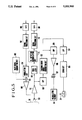
- FIG. 5 is a circuit diagram showing the circuit of the VTR shown in FIG. 1;
- FIG. 6 is an illustration of a modification of the VTR shown in FIG. 1;
- FIG. 7 is an illustration of a mechanical portion of a VTR as another embodiment of the present invention.
- FIG. 8 is an illustration of the VTR mechanism of FIG. 7 is an unloading state
- FIG. 9 is an illustration of a mechanical portion of a VTR as still another embodiment of the invention.
- FIG. 10 is an illustration of a modification of the VTR shown in FIG. 9.
- FIG. 11 is an illustration of another modification of the VTR shown in FIG. 9.
- FIG. 1 shows in plan a mechanical portion of a VTR as an embodiment of the present invention.
- the VTR has, as known per se, the following parts: a rotary head drum 10; a tape cassette 12; guide posts 14 to 22; a capstan 24; a pinch roller 26; an erasing head 28; fixed heads 30 to 32; an inlet skate unit 34; an outlet skate unit 36; an inlet catcher 38; an outlet catcher 40; an inlet rail 42; an outlet rail 44; reels 46 and 48; and a magnetic tape 50.
- FIG. 1 solid lines show the mechanical portion in a loading completion state, while broken-lines show the mechanism in an unloading state, i.e., the state in which the tape 50 is housed in the cassette 12.
- unloading state the same members or parts as in the loading completion state are designated by the same reference numerals with "a" attached thereto.
- the magnetic tape 50 is wound helically around the rotary head drum 10. Recording or reproduction of signals is conducted by means of a rotary head carried by the rotary head drum 10 while the magnetic tape 50 is made to run from the reel 46 to the reel 48 by the capstan 24.
- posts 17 and 20 are simultaneously moved in the same direction as indicated by arrows Y i and Y o during the recording or reproduction, so as to adjust the position of the magnetic head relative to the tape 50, thereby enabling an appropriate tracking control.
- the posts 17 and 20 are provided on the skate units 34 and 36 together with the posts 18 and 19. Loading of the tape 50 is performed by shifting the skate units 34 and 36, the posts 15 and 22 and the pinch roller 26 along paths shown by one-dot chain lines in FIG. 1, by means of a lever which is not shown, as publicly known per se.
- the skate units 34 and 36 are gripped by the catchers 38 and 40.
- FIGS. 2 and 3 show, in plan and in side elevation, the inlet skate unit 34 and the catcher 38 in the state immediately before the former is engaged by the latter.
- the post 17 is omitted from FIG. 2, while screws 68 and 69 shown in FIG. 2 omitted from FIG. 3.
- a reference numeral 52 denotes a base
- 54 denotes a piezoelectric element
- 56, 57 and 58 denote pins
- 60 denotes a circuit board
- 62 and 63 denote electrical contacts on the circuit board 60
- 64 and 65 denote terminals
- 66 to 69 denote screws
- 70 and 72 denote leads.
- a pressing of the pin 58 by a lever which is not shown causes the skate unit 34 to be moved in the direction of an arrow S, so that the pins 56 and 57 are brought into engagement with a V-groove and a U-groove of the catcher 38, so that an abutting surface 74 of the end of the base 52 abuts a positioning surface 75 of the catcher 38 while the underside 76 of the base 52 abuts a reference surface of a chassis (not shown), whereby the skate unit 34 is positioned.
- the catcher 38 is fixed by the screws 68 and 69, with its lower surface 77 contacting the reference surface of the chassis.
- the electrical contacts 62 and 63 of the circuit board 60 fixed to the upper surface of the base 52 are brought into electrical connection with terminals 64 and 65 fixed by the screws 66 and 67 to the catcher 38, thus enabling supply of electrical power to the piezoelectric element 54 on the skate unit 34 through leads 70 and 72.
- the electrical contacting portions of the described parts may be suitably plated with, for example, gold, for the purpose of reducing the contact resistance.
- an electrically insulating plastic material is used as the material of the catcher 38, and the terminals 64 and 65 are directly fixed to the catcher 38.
- the terminals 64 and 65 maybe directly fixed to the catcher 38 through an insulating plate such as a circuit board.
- the piezoelectric element 54 is of a so-called lamination type which changes its thickness according to the voltage applied thereto.
- the piezoelectric element is expandable and contractable in the direction of an arrow X.
- the expansion and contraction of the piezoelectric element cause the arm 80 to be moved in the direction of an arrow Y around a point P on the base 52.
- the amount of expansion and contraction of the laminate type piezoelectric element 54 is in general as small as several tens of micron meters ( ⁇ m) or smaller. Therefore, an arm 80 is used such that the length B (see FIG.
- a pin 82 provided on the end of the arm 80 rotatably supports the post 17.
- the skate unit 36 and the catcher 40 on the outlet side are constructed and arranged in the same manner as the skate unit 34 and the catcher 38 on the inlet side, so that the inlet side post 17 and the outlet side post 20 are movable in the directions of the arrows Y i and Y o in FIG. 1.
- the piezoelectric element associated with the skate unit 36 is controlled in the expanding direction
- the piezoelectric element associated with the skate unit 34 is controlled in the contacting direction. With this arrangement, it is possible to move the tape 50 on the rotary head drum 10.
- a symbol T represents the track after the recording
- l represents the tracing locus of the center of a magnetic head 90 carried by the rotary head drum
- t represents the locus of movement of the center of the track T.
- the locus l and the locus t wind with respect to straight lines with winding amplitude on the order of several micron meters ( ⁇ m) with respect to a straight line.
- Control techniques presently available can reduce the winding amplitude only to 3 to 10 ( ⁇ m). Therefore, when the track width is reduced to such minimum winding amplitude, the position of the rotary head easily comes off the desired track as illustrated in FIG. 4.
- the magnetic tape 50 is instantaneously moved in the longitudinal direction of the tape as shown by an arrow 92 in FIG. 4, by adjusting the positions of the posts 17 and 20, in full contrast to the conventional tracking control method in which the magnetic head 90 is moved in the direction orthogonal to the track T as indicated by an arrow 94 in FIG. 4.
- the winding of the track has many components but most of them have one to two periods per track. Therefore, the response speed for enabling the head to trace the track one to 2 times as high as the rotation speed of the rotary head drum.
- the angle ⁇ of inclination of the track is 6° and the maximum value from peak to peak of offset of l from the track center t is 10 ⁇ m.
- the amount of movement required for the magnetic tape 50 for effecting the tracking control is calculated as 10 ⁇ m/sin 6° ⁇ 96 ⁇ m.
- symbols S 1 and S 2 show the positions of the head on the track, as obtained when the head 90 is moved and when the tape 50 is moved, respectively.
- This difference in the position appears as an offset of the time axis of the reproduced signal.
- this offset of the time axis undesirably causes a jitter.
- it is necessary to employ a suitable measure such as a correction of the time axis by a time axis correction circuit or a change in the speed of rotation of the rotary drum.
- a suitable measure such as a correction of the time axis by a time axis correction circuit or a change in the speed of rotation of the rotary drum.
- no substantial problem is caused by the offset of the time axis because the data is reproduced in accordance with clocks which follow the reproduction signal by the PLL.
- FIG. 5 is a block diagram of a recording/reproducing circuit including a circuitry for the tracking.
- a known four-frequency type control system ordinarily used in 8 mm VTRs, is used in this circuit by way of example.
- an analog input video signal is digitized by an A/D converter 100 and a processing such as addition of an error signal and an interleave are effected by a digital signal processing circuit 102.
- the processed video signal is modulated into a signal suitable for magnetic recording, by means of the modulation circuit 104 and is then supplied to the adder 105.
- a tracking control pilot signal generated by a pilot signal generating circuit 103 is added to the modulated signal.
- the signal is then suitably amplified by a recording amplifier 106 and is applied to a magnetic head 108, whereby the signal is recorded on the magnetic tape 50.
- the magnetic head 108 may be arranged in plural. It is unnecessary to apply a voltage to the piezoelectric element 54 during recording.
- the capstan 24 is required only to drive the magnetic tape 50 at a constant speed.
- the reproducing operation is as follows.
- the reproduction output from the head 108 is amplified by a reproduction amplifier 110 and is shaped by an equalizer 112 and is demodulated by the PLL detection demodulation circuit 114 in the order reverse to that in the recording.
- processes such as error correction and de-interleave are performed by a digital signal processing circuit 116.
- the output from the processing circuit 116 is converted into an analog signal by means of a D/A converter 118.
- the tracking control signal which is superposed to a digital signal in a low-frequency band of the reproduction signal, is picked up by means of a band-pass filter (BPF) 120.
- BPF band-pass filter
- a tracking error signal generating circuit 122 generates a tracking error signal from the output of the BPF 120 in a manner known per se.
- a tracking error signal delivered from the circuit 122 is applied to a capstan servo circuit 126 through a low-pass filter 124 so as to control the running speed of the tape 50 through a control of the capstan 24.
- the response frequency of the tracking servo system relying upon the control of the capstan 24 is as low as several hertz (Hz) or lower due to inertia and load on the capstan motor. Such a low response frequency is insufficient for enabling the head to trace any winding or curvature of the track. It may be possible to overcome this problem, by the use of a high-torque low-inertia motor as the capstan motor. Such a countermeasure, however, is not preferred because such a motor causes a fluctuation in the signals reproduced by the fixed heads 30, 31 and 32 which are in the tape path.
- a frequency component corresponding to the winding of the track is picked up from the tracking error signal by means of a BPF 128 and is applied to the piezoelectric element 54 after boosting by an amplifier 130 and the transformer 132, thereby causing the piezoelectric element 54 to drive the posts 17 and 20 simultaneously in the same direction as explained before, whereby the magnetic tape 50 is made to move.
- This operation is encountered only with a small resistance or load produced as a result of friction between the magnetic tape 50 and the posts 18 and 19 and the rotary head drum 10.
- no influence is caused on the signal reproduced by the fixed heads 30, 31 and 32.
- the driving voltage for driving the piezoelectric element 54 is as high as several hundreds to several thousands volts. In the described embodiment, however, it suffices only to apply the high-frequency component of the tracking error signal to the piezoelectric element 54. This can be done by means of a transformer so that the cost of the circuit can be reduced.
- the piezoelectric elements 54 secured to the skate units 34 and 36 are supplied with electrical power through contacts 62 and 63 and terminals 64 and 65. Such contacts and terminals can be made of inexpensive material because they are required only to make and break the contact at the time of loading, unlike the brushes used in the conventional apparatus.
- FIG. 6 shows a modification of the skate unit.
- the same reference numerals are used to denote the same parts or members as those appearing in FIG. 2.
- a bimorph-type element 140 is used as the piezoelectric element.
- the piezoelectric element 140 is fixed to a base 52 through an intermediary of a spacer 142 which provides a predetermined space between the piezoelectric element 140 and the base 52.
- the bimorph-type piezoelectric element is composed of a pair of piezoelectric elements of different directions of polarization bonded together, and is deflected in accordance with the level of the voltage applied thereto, so as to cause a movement of the post 17 in the direction Y of FIG. 6.
- the contacts 62 and 63 of the skate units 34 and 36 and the terminals 64 and 65 of the catchers 38 and 40 are electrically connected upon completion of the loading so as to temporarily form a path of electrical power supply to the piezoelectric element 54 which serves as post driving means.
- the electrical power supply to the piezoelectric element 54 may be provided by a permanent wiring such as leads and a flexible substrate, if such a permanent wiring does not hinder the movement of the magnetic tape and other parts when the skate units 34 and 36 carrying the piezoelectric elements 54 are moved.
- the described embodiment allows a tracking control for enabling a head to trace any winding of a track by a simple construction. This in turn makes it possible to produce a recording/reproducing apparatus operative with narrow tracks, i.e., with a high recording density.
- FIG. 7 illustrates a mechanical portion of a VTR as another embodiment of the invention.
- the same reference numerals are used to denote the same parts or members as those appearing in FIG. 1, and description of such parts or members is omitted to avoid duplication of explanation.
- the mechanism shown in FIG. 7 is in the state after completion of the tape loading. Loci or paths of movement of the posts 15 and 22 and the pinch roller 26 in the tape housing condition are shown by one-dot chain lines by way of reference.
- the posts 17 and 20 are simultaneously moved in the directions of arrows Y i and Y o during recording or reproduction so as to adjust the position of the magnetic head relative to the tape 50, thereby enabling adequate tracking control.
- the mechanism for moving the posts 17 and 20 will be described below.
- Levers 151 and 152 are provided at the inlet side. These levers are adapted to be rotated in the direction of an arrow Xi at the time of tape loading, about the axis 154 of a pin 153 on the lever 152, by the action of a lever or the like member which is not shown.
- the lever 151 is pressed by the action of a torsion spring 155 against a portion of an arm 156 of the skate unit 34 carrying the post 17, near a fulcrum 157 which is on a base portion of the arm 156.
- the portion of the arm 156 near the fulcrum 157 is made of an elastic material.
- a laminate-type piezoelectric element 158 fixed to the lever 151 is capable of being supplied with electrical power from a circuit board 159.
- a driving voltage is applied to the piezoelectric element 158 with the lever 151 pressed onto the portion of the arm 156 near the fulcrum 157, the arm 156 is swung about the fulcrum 157, thereby enabling the post 17 to be adjusted in the direction of the arrow Yi.
- a laminate-type piezoelectric element can produce a displacement which is as small as several tens of micron meters ( ⁇ m) at the greatest. In this embodiment, therefore, the displacement is amplified 10 times by the arm 156 which serves as a lever.
- the arrangement at the outlet side includes levers 171 and 172, a pin 173 with an axis 174 of rotation, a torsion spring 175, an arm 176 of the skate unit 36, a fulcrum 177 for rotation of the arm 176, a laminate-type piezoelectric element 178, and a circuit board 179 for supplying a driving voltage to the piezoelectric element 178.
- the portion of the arm 176 around the fulcrum 177 is made of an elastic material.
- FIG. 8 shows the mechanism of FIG. 7 in a tape unloading state.
- the lever 152 on the inlet side and the first lever 172 on the outlet side are rotated in the directions opposite to the arrows X i and X o by the action of the pins 153 and 173, the levers 151 and 171 are rotated as they are pushed by projections 160 and 180 of the levers 154 and 174 into positions where they do not hinder the movement of the skate units 34 and 36.
- the arrangement is such that the movement of the pins 153 and 173 is effected during charging of these units by a spring after being stopped by the catchers 38 and 40 or after the charging.
- the movement of the skate unit 34 and 36 is caused by levers or suitable members which push the pins 161 and 181. Needless to say, however, the direction of movement of the skate units 34 and 36 is not reverse to that of the pressing force acting on the levers 151 and 171 in the loading completion state shown in FIG. 7.
- the tracking control operation performed by the mechanism shown in FIGS. 7 and 8 is substantially the same as that of the embodiment described before in connection with FIGS. 1 to 5, so that description of operation is omitted.
- FIGS. 7 and 8 also provides a simple construction which enables the head to trace any winding of the track on the recording tape, thus realizing a recording/reproducing apparatus operable with narrow tracks, i.e., with a high recording density, as is the case of the embodiment described in connection with FIGS. 1 to 5.
- the electrical contact for the supply of the electrical power to the piezoelectric elements 158 and 178 are dispensed with, thus contributing to a simplification of the construction.
- FIG. 9 is an illustration of a mechanical portion of a VTR which is still another embodiment of the present invention.
- the same reference numerals are used to denote the same parts or members as those appearing in FIG. 1.
- Numerals 216 through 225 denote tape guide posts.
- An inlet-side lever 234 and an outlet-side lever 236 are movable in the directions of arrows Yi and Yo, respectively.
- a numeral 238 denotes a rocker lever, while a numeral 240 designates a laminate-type piezoelectric element for driving the rocker lever 238.
- a pin 241 is provided on the inlet-side lever 234 and is loosely received by a hole 242 formed in the end of the rocker lever 238.
- Numerals 243 and 244 denote guide pins which limit the direction of movement of the inlet-side lever 234. With this arrangement, it is possible to convert the movement of the rocker lever 238 into a movement of the inlet-side lever 234 in the direction of the arrow Yi. Similarly, a pin 245 is provided on the outlet-side lever 236 and is loosely received in a hole 246 formed in the end of the rocker lever 238. Numerals 247 and 248 denote guide pins for limiting the direction of movement of the outlet-side lever 236. With this arrangement, it is possible to convert the movement of the rocker lever 238 into a movement of the outlet-side lever 236 in the direction of an arrow Yo.
- a numeral 252 denotes a shaft which serves as a fulcrum for the rocking motion of the rocker lever 238, while 254 denotes a spring for pre-loading the piezoelectric element 240.
- FIG. 9 shows the mechanism in a loading completion state. This figure also shows positions of parts in the state after the housing of the tape 50 in the cassette 12, with "a" attached to each of reference numerals designating these parts. The loci or paths of movement of these parts from the positions where they are set in the tape housing state to the positions where they are set in the loading completion state are indicated by broken-line arrows.
- the posts 15, 22, 217, 219, 220, 221, 222 and 224 on the inner side of the tape running path are moved, by the action of a lever which is not shown, from the positions in the window of the cassette 12 denoted by 15a, 22a, 217a, 219a, 220a, 221a, 222a and 224a to the illustrated positions along the paths shown by the broken-line curves, thereby forming the tape-running path.
- the pinch roller 26 is moved from upper side into contact with the capstan 24 after the tape running path is formed.
- the capstan 24 is driven so as to cause the magnetic tape 50 from the reel 46 to the reel 48 and, at the same time, the rotary head drum 10 is rotated for recording or reproduction.
- the magnetic tape 50 is wound onto the rotary head drum 10 helically.
- the posts 218 and 223 are simultaneously moved by the piezoelectric element 240 in the directions of arrows Yi and Yo during recording and reproduction, thereby adjusting the position of the magnetic tape relative to the tape 50, thus realizing an adequate tracking control. More specifically, when the driving voltage corresponding to the tracking error signal is applied to the piezoelectric element 240, the piezoelectric element 240 produces a displacement in the direction of the arrow X substantially in proportion to the voltage applied thereto.
- the post 223 is moved by the same amount as the post 218 in a direction to tension the magnetic tape 50.
- the portion of the magnetic tape 50 between the posts 218 and 223 is moved from the inlet side to the outlet side of the rotary head drum 10 along the path of running of the tape 50.
- the post 223 moves in the direction for slackening the tape 50. It will be seen that the movement of the magnetic tape 50 in the direction of running thereof can be effected without encountering with a substantial change in the tape tension because the posts 218 and 223 are moved by an equal amount.
- the tension applied to the tape in the region near the post 218 is 1.3 to 2.0 times as high as the tension applied to the tape portion near the post 223.
- the tensions are reversed so that a negative force is applied to the piezoelectric element 240. It is therefore advisable to pre-load the piezoelectric element 240 by a spring 254.
- the tracking control operation performed by this mechanism is substantially the same as that explained in connection with FIG. 1, so that description thereof is omitted.
- the amplification of the displacement produced by the piezoelectric element, which is performed by the rocker lever 238 in this case, may be performed by a suitable link mechanism.
- a suitable link mechanism Such a modification will be described with reference to FIG. 10.
- the same reference numerals are used to denote the same parts or members as those appearing in FIG. 9, and detailed description thereof is omitted.
- a lever 260 is swingably supported at its one end by a shaft 261 provided on a chassis.
- the other end of the lever 260 is connected through a pin 262 to a lever 263.
- the arrangement is such that the surface of the piezoelectric element 264 drives the pin 262.
- the end of the lever 263 is connected to a lever 266 through a pin 265, and the lever 266 is guided by guide pins 267 and 268 so as to move only in the direction of the arrow X 1 .
- the displacement produced by the piezoelectric element 264 in the direction X is amplified by the levers 260 and 263 and is converted into a large displacement of the lever 266 in the direction X 1 .
- the lever 266 is provided at its one end with a pin 269 which is engaged by one end of a lever 270 so that the lever 270 is rotatable about the axis of the shaft 271.
- the other end of the lever 270 engages with the pin 241 on the lever 234. Therefore, a displacement of the lever 266 in the direction X 1 causes the lever 270 to rotate about the axis of the shaft 271, which in turn causes a corresponding displacement of the lever 234 in the direction Yi.
- the lever 266 is provided at its other end with a pin 272 which is engaged by one end of a lever 273 rotatable about the axis of a shaft 274. The other end of the lever 273 engages with a pin 245 on the lever 236.
- a displacement of the lever 266 in the direction X1 causes a displacement of the lever 236 in the direction Yo.
- the displacement generated by the piezoelectric element 264 causes the posts 218 and 223 to move in the directions Yi and Yo, respectively, thereby shifting the tape 50 forward or backward in the direction of running thereof.
- the inertia can be reduced rather easily as compared with the embodiment of FIG. 9, so that a higher response frequency can be obtained.
- FIG. 10 employs a piezoelectric element 264 as the source of the driving power.
- This is not exclusive and the embodiment shown in FIG. 10 may be modified such that a pulse motor is used in place of the piezoelectric element 264, as will be explained hereinafter with reference to FIG. 11.
- FIG. 11 the same reference numerals are used to denote the same parts or members as those appearing in FIG. 10, and parts which are common to those in the arrangement shown in FIG. 9 are omitted.
- the modification shown in FIG. 11 has a pulse motor 276, a worm gear 277, a gear 278 and a rack 279 which is fixed to the lever 266.
- the output rotation of the pulse motor 276 is transmitted to the rack 279 at a reduced speed through the worm gear 277 and the gear 278 so as to move the lever 266 in the direction X 1 .
- the posts 218 and 223 are displaced in the directions Yi and Yo, respectively.
- the pulse motor 276 in general cannot have high resolution, the positions of the posts 218 and 223 can be controlled with a resolution of 10 ⁇ m or less through the speed reduction conducted at a suitable speed reduction ratio.
- the response characteristic of this modification depends on the characteristic of the pulse motor.
- the pulse motor provides a higher response frequency as compared with the case where the tracking is controlled by controlling the speed of the capstan motor.
- a higher response speed can be obtained when a low-inertia and high-output motor such as a core-less motor is used as the motor 276.
- an excellent tracking control can be performed to enable the head to well trace any winding of the track, simply by driving a single connecting member (238, 266).
- This control requires only a single tape guide driving mechanism so that advantages are brought about over the arrangements of FIGS. 1 and 7 such as simplification of the electrical wiring.
Abstract
Description
Claims (24)
Applications Claiming Priority (6)
| Application Number | Priority Date | Filing Date | Title |
|---|---|---|---|
| JP63118853A JPH01290150A (en) | 1988-05-16 | 1988-05-16 | Magnetic recording and reproducing device |
| JP63-118853 | 1988-05-16 | ||
| JP63-127002 | 1988-05-26 | ||
| JP63127003A JP2600288B2 (en) | 1988-05-26 | 1988-05-26 | Magnetic recording / reproducing device |
| JP63127002A JP2586576B2 (en) | 1988-05-26 | 1988-05-26 | Magnetic recording / reproducing device |
| JP63-127003 | 1988-05-26 |
Publications (1)
| Publication Number | Publication Date |
|---|---|
| US5053900A true US5053900A (en) | 1991-10-01 |
Family
ID=27313690
Family Applications (1)
| Application Number | Title | Priority Date | Filing Date |
|---|---|---|---|
| US07/347,493 Expired - Lifetime US5053900A (en) | 1988-05-16 | 1989-05-04 | Recording and/or reproducing apparatus performing a tracking control by moving guide members for a recording medium |
Country Status (1)
| Country | Link |
|---|---|
| US (1) | US5053900A (en) |
Cited By (3)
| Publication number | Priority date | Publication date | Assignee | Title |
|---|---|---|---|---|
| US5293283A (en) * | 1991-04-12 | 1994-03-08 | Sony Corporation | Tape guiding assembly for recording and/or reproducing apparatus employing ultrasonically vibrated tape guides |
| US5923494A (en) * | 1995-03-20 | 1999-07-13 | Hitachi, Ltd. | Magnetic tape device and method of controlling magnetic tape device |
| US20100128379A1 (en) * | 2008-11-24 | 2010-05-27 | Quantum Corporation | Guide assembly for reducing lateral tape motion in a tape drive |
Citations (9)
| Publication number | Priority date | Publication date | Assignee | Title |
|---|---|---|---|---|
| US2979558A (en) * | 1957-10-02 | 1961-04-11 | Rca Corp | Recording and reproducing system |
| US4180839A (en) * | 1977-04-05 | 1979-12-25 | Bell & Howell Company | Information reproducing apparatus |
| US4369473A (en) * | 1979-07-20 | 1983-01-18 | U.S. Philips Corporation | Recording and/or reproducing apparatus |
| US4389684A (en) * | 1980-03-06 | 1983-06-21 | Hitachi Denshi Kabushiki Kaisha | Movable tape-guide control system |
| US4485420A (en) * | 1981-04-13 | 1984-11-27 | U.S. Philips Corporation | Magnetic-tape cassette apparatus having very low azimuth error |
| US4639799A (en) * | 1983-11-18 | 1987-01-27 | Victor Company Of Japan, Ltd. | Magnetic tape recording and reproducing apparatus with rotatable drum having inclined heads |
| US4672479A (en) * | 1984-04-04 | 1987-06-09 | Sanyo Electric Co., Ltd. | Tape loading/unloading arrangement for magnetic recording and/or reproducing apparatus |
| US4709280A (en) * | 1984-10-08 | 1987-11-24 | Enertec | Apparatus for varying the path of magnetic tape passing over a rotary tape head |
| US4945426A (en) * | 1987-05-29 | 1990-07-31 | Matsushita Electric Industrial Co., Ltd. | Helical scan tracking system |
-
1989
- 1989-05-04 US US07/347,493 patent/US5053900A/en not_active Expired - Lifetime
Patent Citations (9)
| Publication number | Priority date | Publication date | Assignee | Title |
|---|---|---|---|---|
| US2979558A (en) * | 1957-10-02 | 1961-04-11 | Rca Corp | Recording and reproducing system |
| US4180839A (en) * | 1977-04-05 | 1979-12-25 | Bell & Howell Company | Information reproducing apparatus |
| US4369473A (en) * | 1979-07-20 | 1983-01-18 | U.S. Philips Corporation | Recording and/or reproducing apparatus |
| US4389684A (en) * | 1980-03-06 | 1983-06-21 | Hitachi Denshi Kabushiki Kaisha | Movable tape-guide control system |
| US4485420A (en) * | 1981-04-13 | 1984-11-27 | U.S. Philips Corporation | Magnetic-tape cassette apparatus having very low azimuth error |
| US4639799A (en) * | 1983-11-18 | 1987-01-27 | Victor Company Of Japan, Ltd. | Magnetic tape recording and reproducing apparatus with rotatable drum having inclined heads |
| US4672479A (en) * | 1984-04-04 | 1987-06-09 | Sanyo Electric Co., Ltd. | Tape loading/unloading arrangement for magnetic recording and/or reproducing apparatus |
| US4709280A (en) * | 1984-10-08 | 1987-11-24 | Enertec | Apparatus for varying the path of magnetic tape passing over a rotary tape head |
| US4945426A (en) * | 1987-05-29 | 1990-07-31 | Matsushita Electric Industrial Co., Ltd. | Helical scan tracking system |
Cited By (3)
| Publication number | Priority date | Publication date | Assignee | Title |
|---|---|---|---|---|
| US5293283A (en) * | 1991-04-12 | 1994-03-08 | Sony Corporation | Tape guiding assembly for recording and/or reproducing apparatus employing ultrasonically vibrated tape guides |
| US5923494A (en) * | 1995-03-20 | 1999-07-13 | Hitachi, Ltd. | Magnetic tape device and method of controlling magnetic tape device |
| US20100128379A1 (en) * | 2008-11-24 | 2010-05-27 | Quantum Corporation | Guide assembly for reducing lateral tape motion in a tape drive |
Similar Documents
| Publication | Publication Date | Title |
|---|---|---|
| US4410918A (en) | Helical scan VTR with deflectable head | |
| JPH11339254A (en) | Magnetic recording tape, information storage medium and magnetic tape recording and reproducing system | |
| US4203140A (en) | Helical scan VTR with deflectable head | |
| JP2005502149A (en) | Magnetic servo for recording head | |
| JPS63500210A (en) | Tape guide mechanism for dynamic tracking control | |
| US5062019A (en) | Method and apparatus for accurately positioning a magnetic recording and reproducing head | |
| US5053900A (en) | Recording and/or reproducing apparatus performing a tracking control by moving guide members for a recording medium | |
| US4945426A (en) | Helical scan tracking system | |
| JPH0344374B2 (en) | ||
| JP2600288B2 (en) | Magnetic recording / reproducing device | |
| US3839735A (en) | Transducer head positioning device | |
| JP2586576B2 (en) | Magnetic recording / reproducing device | |
| JPH01290150A (en) | Magnetic recording and reproducing device | |
| JPH0320904Y2 (en) | ||
| JP2603255B2 (en) | Disk unit | |
| JP2591674B2 (en) | Playback device | |
| KR0162224B1 (en) | Tension control performance measuring method for digital vcr | |
| JP3189514B2 (en) | Magnetic head device | |
| JPH0413793Y2 (en) | ||
| JP2506629B2 (en) | High-speed playback device | |
| JPH0673211B2 (en) | Tracking device | |
| JP2963576B2 (en) | Magnetic recording / reproducing device | |
| JPS6226092B2 (en) | ||
| JPH01151044A (en) | Tracking device | |
| JPH0352127B2 (en) |
Legal Events
| Date | Code | Title | Description |
|---|---|---|---|
| AS | Assignment |
Owner name: CANON KABUSHIKI KAISHA, JAPAN Free format text: ASSIGNMENT OF ASSIGNORS INTEREST.;ASSIGNORS:HASEGAWA, MASAHIDE;KIMURA, TAKASHI;REEL/FRAME:005068/0906 Effective date: 19890428 |
|
| STCF | Information on status: patent grant |
Free format text: PATENTED CASE |
|
| CC | Certificate of correction | ||
| FEPP | Fee payment procedure |
Free format text: PAYOR NUMBER ASSIGNED (ORIGINAL EVENT CODE: ASPN); ENTITY STATUS OF PATENT OWNER: LARGE ENTITY |
|
| FPAY | Fee payment |
Year of fee payment: 4 |
|
| REMI | Maintenance fee reminder mailed | ||
| FEPP | Fee payment procedure |
Free format text: PAYER NUMBER DE-ASSIGNED (ORIGINAL EVENT CODE: RMPN); ENTITY STATUS OF PATENT OWNER: LARGE ENTITY Free format text: PAYOR NUMBER ASSIGNED (ORIGINAL EVENT CODE: ASPN); ENTITY STATUS OF PATENT OWNER: LARGE ENTITY |
|
| FPAY | Fee payment |
Year of fee payment: 8 |
|
| FPAY | Fee payment |
Year of fee payment: 12 |