US5053202A - Static mixer configuration - Google Patents
Static mixer configuration Download PDFInfo
- Publication number
- US5053202A US5053202A US07/562,495 US56249590A US5053202A US 5053202 A US5053202 A US 5053202A US 56249590 A US56249590 A US 56249590A US 5053202 A US5053202 A US 5053202A
- Authority
- US
- United States
- Prior art keywords
- elements
- mixer
- spacer
- static mixer
- dispensing apparatus
- Prior art date
- Legal status (The legal status is an assumption and is not a legal conclusion. Google has not performed a legal analysis and makes no representation as to the accuracy of the status listed.)
- Expired - Fee Related
Links
Images


Classifications
-
- B—PERFORMING OPERATIONS; TRANSPORTING
- B01—PHYSICAL OR CHEMICAL PROCESSES OR APPARATUS IN GENERAL
- B01F—MIXING, e.g. DISSOLVING, EMULSIFYING OR DISPERSING
- B01F25/00—Flow mixers; Mixers for falling materials, e.g. solid particles
- B01F25/40—Static mixers
- B01F25/42—Static mixers in which the mixing is affected by moving the components jointly in changing directions, e.g. in tubes provided with baffles or obstructions
- B01F25/43—Mixing tubes, e.g. wherein the material is moved in a radial or partly reversed direction
- B01F25/431—Straight mixing tubes with baffles or obstructions that do not cause substantial pressure drop; Baffles therefor
- B01F25/4312—Straight mixing tubes with baffles or obstructions that do not cause substantial pressure drop; Baffles therefor having different kinds of baffles, e.g. plates alternating with screens
-
- B—PERFORMING OPERATIONS; TRANSPORTING
- B29—WORKING OF PLASTICS; WORKING OF SUBSTANCES IN A PLASTIC STATE IN GENERAL
- B29C—SHAPING OR JOINING OF PLASTICS; SHAPING OF MATERIAL IN A PLASTIC STATE, NOT OTHERWISE PROVIDED FOR; AFTER-TREATMENT OF THE SHAPED PRODUCTS, e.g. REPAIRING
- B29C44/00—Shaping by internal pressure generated in the material, e.g. swelling or foaming ; Producing porous or cellular expanded plastics articles
Definitions
- the present invention relates generally to apparatus used to dispense a plurality of liquids through a single orifice, and more particularly it relates to a static mixer used to enhance the mix quality of polyurethane foam from a foam dispenser utilized without the need for solvent cleaning.
- Polyurethane foams are formed by the reaction of an isocyanate component and hydroxyl-bearing compounds. When mixed in the presence of a catalyst, a surfactant, and a blowing agent, these chemicals react to form cellular cross-linked polymer chains, more commonly known as a polyurethane foam.
- a catalyst, a surfactant, and a blowing agent react to form cellular cross-linked polymer chains, more commonly known as a polyurethane foam.
- Each of these components of the plural component material by itself, is generally stable. Thus, each component will not cure or cross-link for extended periods of time, often as long as several months, if they are properly stored.
- the isocyanate component and the polyol component a preformulated compound that includes a surfactant, a catalyst and a blowing agent, are mixed together in proper proportions, an exothermic chemical reaction of the isocyanate and polyol occurs. This reaction causes a continued expansion that is evidence of the polymerization and manifests itself as foam which cross
- Polyurethane foam dispensers are well known and have achieved a high degree of usage in insulating or packaging applications. Their use is particularly widespread in the boat manufacturing industry where foam is used to enhance the buoyancy of the watercraft. This type of a manufacturing application requires a low density foam that can be dispensed by apparatus in a potentially combustible or explosive environment.
- foam dispensing equipment used in the marine industry involves the need to obtain a fully expanded low density foam that has not lost some of its fluorocarbons.
- Prior foam dispensing apparatus has employed static mixer attachments made from either metal or plastic, such as by injection molding, that use alternating left and right handed helically-curved baffles to intermix a plurality of fluids.
- Representative apparatus of this type utilized to mix and blend polymeric fluids include those shown in U.S. Pat. Nos. 3,953,002; 4,408,493; 4,840,493; and 4,850,750.
- Two banks of stationary non-helical baffle plates arranged around an axis parallel to the overall direction of fluid flow have been used to accomplish the desired mixing and blending, as shown in U.S. Pat. No. 4,093,188. However, these devices do not always yield the desired low density foam needed for marine applications.
- the improved static mixer configuration employs a generally planar spacer Portion intermediate serially arranged oppositely handed baffle members that are contained within a disposable tubular housing that is attached to a foam dispensing apparatus.
- the oppositely handed baffle members form at least a pair of passages within the tubular housing on the sides of the baffles.
- a compressed air infeed is provided into the static mixer configuration to increase the mixing energy of the apparatus.
- the improved static mixer design achieves the required mix and entrapment of chemical blowing agents to obtain the desired free-rise foam density with the desired color and cell structure.
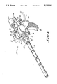
- FIG. 1 is a perspective view of a foam dispensing apparatus employing the improved static mixer configuration of the present invention
- FIG. 2 is a side elevational view of the improved static mixer configuration within its tubular housing
- FIG. 3 is an exploded side elevational view of the improved static mixer configuration of FIG. 2 without the tubular housing;
- FIG. 4 is a side elevational view of an alternative embodiment of the improved static mixer configuration within its tubular housing having a void space or spacing gap between the mixing elements;
- FIG. 5 is a side elevational view of another alternative embodiment of the improved static mixer configuration within its tubular housing having a plurality of spacer elements.
- FIG. 1 shows in a top perspective view the foam dispensing apparatus, indicated generally by the numeral 10.
- dispenser 10 has a gun manifold 11 with a static mixer 12 attached to the front of the manifold 11.
- a trigger 14 is shown mated to a handle 15.
- the isocyanate A side feed line 16 can be seen, while the polyol B side feed line is not visible.
- An air entry line 18 is shown entering the rear of the manifold 11. This air entry line 18 is used to feed air in through the isocyanate A side of the manifold 11 to enhance the mixing of the foam components.
- An isocyanate A side valve assembly 19 is shown, as is the polyol B side valve assembly 21, each containing a stem or rod 20 within the manifold 11.
- Each valve assembly has a metal rod 20 with a rubber tip (not shown) within the manifold 11 to control the flow of the isocyanate A side component and the polyol B side component through the internal flow passages or orifices (not shown) in the manifold 11. Only one of the metal rods 20 (the isocyanate A side metal rod 20) is shown.
- a power cord 22 is shown for use with the electric trigger, although it may be preferable to employ an pneumatic trigger where the dispenser 10 is used in a potentially explosive atmosphere.
- An air cylinder 25 is shown attached to the manifold 11 by a mounting bracket 29 and is activated by the trigger 14.
- the air cylinder 25 includes a pneumatically driven cylinder rod 26 which pushingly contacts a valve arm coupling 28 that opens and closes the flow passages or orifices to control the flow of components within the manifold 11 by limited rotation of the valve arms 24 and the valve assemblies 19 and 21 to which the valve arms 24 are attached.
- the static mixer 12 is connected to the manifold 11 by means of a swivel fitting that comprises a rigid portion 30 that is affixed over the mounting bracket 29 to the manifold 11.
- a rotational portion 31 of the swivel fitting is used to tighten the fitting with the static mixer 12 to the manifold 11.
- An adaptor 32 is provided which, in combination with tighten down nut 34 through which the tubular housing 42 of the static mixer 12 extends, is utilized to securely fasten the static mixer 12 to the manifold 11.
- the static mixer 12 is thus simply fastened to the manifold 11 so that it is easily disconnected and disposed of should the air cleaning or air purge, to be described more fully hereafter, not be fully effective and the mixer 12 become clogged.
- the static mixer 12 is best seen in FIG. 2 wherein it comprises a plurality of oppositely handed spiral segments or helical mixer elements 39.
- the mixed A and B side isocyarate and polyol components after having traveled &he length of the housing 42, exit the tubular housing 42 of the static mixer 12 through a dispensing orifice 40.
- the surface of the tubular housing 42 around the orifice 40 must be smooth and clean to avoid providing spaces for the buildup of foam which can eventually clog the static mixer 12.
- This tubular housing 42 surrounds the mixer elements 39 and the static mixer spacer 38.
- a base portion 41 of the static mixer 12 fits within the tighten down nut 34 of FIG. 1 so that the base portion is retained on the interior of the tighten down nut 34 and the tubular housing 42 extends therethrough.
- the static mixer spacer 38 is preferably a single planar plastic sheet that is about 0.040 inches thick, but may be made more rigid by being as thick as 1/16 of an inch. This spacer 38 separates the mixer elements 39 into fore and aft sections.
- the spacer 38 can separate an equal number of elements 39, or can have unequal numbers on the fore and aft sections as desired and is necessary for the different foam formulations utilized. Twelve segment elements have been successfully employed on each side of the spacer 38.
- the spacer elements 39 are detachably fastened to the mixer spacer 38 by appropriate means, such as by interlocking spacer notches 36 and mixer element notches 37.
- the length of the spacer 38 can vary with reference to the overall length of the static mixer 12. Lengths successfully employed have been about 1.5 inches and about 2.5 inches. With a 10 inch length of mixer elements 39, this gives a ratio of lengths of the spacer 38 to the mixer elements 39 of between about 0.10 to about 0.30 and, more preferably about 0.15 to about 0.25.
- the overall length of the static mixer 12 with its tubular housing 42 is about 13 inches.
- the tubular housing 42 has about a 0.5 inch inside diameter and about a 0.375 inch orifice or opening at its dispensing end.
- An air assist can be employed in the mixing of the isocyanate component A and the polyol component B by being fed in through the air entry line 18 into the isocyanate A component side through a hole that may be as small as 0.015 inches in diameter in the A side port. It has been found that this compressed air, when fed at a pressure of between about 80 to about 125 pounds per square inch, and preferably at about 90 pounds per square inch, enhances the final mix of the foam and obtains the proper or desired density of the urethane foam. The air flow is about 0.37 cubic feet per minute at 90 pounds per square inch. A desired density has been about 1.8 to about 2.0 pounds per cubic foot. It is theorized that this air assist provides extra energy to improve the mixing of the isocyanate and polyol components.
- This air enters the isocyanate A side component stream in the front portion of the manifold 11 of the dispenser 10.
- the air is fed by way of two inline valves (not shown).
- the first merely opens or closes the main air line.
- the second valve positioned serially between the first main air line flow valve and the manifold 11, is a two position mix valve that can operate in a fully opened Position where air is blown through the isocyanate A side of the gun to assist in cleaning, or in a mid-way position as the air assist to enhance the mixing of the isocyanate and polyol components by imparting more energy to the isocyanate feed stream.
- the mix valve has about a 1/8 inch diameter opening in the ball valve to permit the purge stream of air to pass through to the manifold 11 and the static mixer 12.
- the opening for the air assist stream is about 0.015 inches in diameter.
- the compressed air source should be filtered for moisture before being connected to the dispenser 10.
- the air cylinder 25 operates with a cam type of system in valve assemblies 19 and 21 such that when the rod 26 is in the forward position, the flow passages or orifices within the manifold 11 are open permitting the flow of the isocyanate and polyol components therethrough.
- the orifices are closed by the rotation of the cams (not shown) within the valve assemblies 19 and 21.
- this type of a portable or on-site Polyurethane foam generating apparatus usually comprises two storage tanks for supplying the two inter-reactive polyurethane-forming materials which are the isocyanate and polyol components.
- a gas pressure supplying system is provided to pressurize these tanks to expel or force the reactants out therefrom through the feed lines to the dispenser 10.
- the static mixing chamber is supplied in the form of the static mixer 12 to receive the flow of the isocyanate A and the polyol B side components from the flow orifices within the manifold 11.
- a typical foam dispenser corresponding to dispenser 10 is shown and described in U.S. Pat. No.
- the mixing elements 39 may be of any suitable serially segmented type, such as that described in U.S. Pat. No. 4,850,705.
- FIG. 4 shows an alternative embodiment of the static mixer 12 employing a void space or spacing gap 44 between the mixing elements 39.
- the elements 39 are maintained in position by suitable retaining devices, such as crimps 45 in the tubular housing 42.
- the length of the void space or spacing gap 44 can be the same as the length of the spacer 38 seen in FIG. 2, or longer or shorter as desired.
- the space 44 serves the same purpose as the spacer 38, but does not separate the foam being mixed and blended by the mixer elements 39 as does the solid mixer spacer 38 of FIGS. 1-3.
- a plurality of spaces 44 could also be employed within the housing 42 similar to the design shown in FIG. 5.
- FIG. 5 shows a second alternative embodiment of the static mixer 12 employing a plurality of mixer spacers 38 of FIG. 2 within the tubular housing 42.
- the actual number employed may be varied depending upon the desired length of the tubular housing and the number of segmented mixer elements 39 employed.
- the dispenser 10 is activated by depression of the trigger switch 14 which allows air to activate the air cylinder 25 and force the cylinder rod 26 forward to the open position by rotating the cams within the valve assemblies 19 and 21 to push the rubber tipped stems of the isocyanate A component and the polyol B component valve assemblies 19 and 21 outwardly to permit the flow of the isocyanate and polyol components through their respective feed lines into the manifold 11.
- the flow streams of the isocyanate A and the polyol B components are kept separate until routed into the static mixer 12 at the front of the manifold 11.
- An air assist feed stream is fed in through the air entry line 18 into the isocyanate A component side port to enhance the mixing of the isocyanate and polyol components.
- the isocyanate A and the polyol B components are fed under pressure into the static mixer tube and swirl about the stationary mixing elements 39, with the assistance of the air feed, to obtain a proper blending and mix.
- the generally planar mixer spacer 38 permits the foam to expand for the finite short distance it must travel toward the orifice 40 without further rotational guidance from the mixer elements 39.
- This short span of travel of the foam components in their partially mixed state continues until the foam comes into contact with the serially segmented mixer elements 39 which again commence the oppositely handed spiral or helical rotation about the mixer elements 39 toward the orifice 40.
- the fully mixed and blended polyurethane foam then exits the dispenser apparatus 10 through the orifice 40.
- the generally planar mixer spacer 38 may be formed with a plurality of holes in it when constructed of a sufficiently rigid material to withstand the mixing pressure and not collapse. Accordingly, the spirit and broad scope of the appended claims is intended to embrace all such changes, modifications and variations that may occur to one of skill in the art upon a reading of the disclosure. All patent applications, patents and other publications cited herein are incorporated by reference in their entirety in pertinent part.
Abstract
Description
Claims (18)
Priority Applications (1)
| Application Number | Priority Date | Filing Date | Title |
|---|---|---|---|
| US07/562,495 US5053202A (en) | 1990-08-02 | 1990-08-02 | Static mixer configuration |
Applications Claiming Priority (1)
| Application Number | Priority Date | Filing Date | Title |
|---|---|---|---|
| US07/562,495 US5053202A (en) | 1990-08-02 | 1990-08-02 | Static mixer configuration |
Publications (1)
| Publication Number | Publication Date |
|---|---|
| US5053202A true US5053202A (en) | 1991-10-01 |
Family
ID=24246507
Family Applications (1)
| Application Number | Title | Priority Date | Filing Date |
|---|---|---|---|
| US07/562,495 Expired - Fee Related US5053202A (en) | 1990-08-02 | 1990-08-02 | Static mixer configuration |
Country Status (1)
| Country | Link |
|---|---|
| US (1) | US5053202A (en) |
Cited By (15)
| Publication number | Priority date | Publication date | Assignee | Title |
|---|---|---|---|---|
| WO1992018251A1 (en) * | 1991-04-22 | 1992-10-29 | Fomo Products, Inc. | Multi-component dispensing apparatus and mixing nozzle for use in said gun |
| US6105880A (en) * | 1998-01-16 | 2000-08-22 | The Sherwin-Williams Company | Mixing block for mixing multi-component reactive material coating systems and an apparatus using same |
| US6375096B1 (en) | 2000-03-01 | 2002-04-23 | Cleveland State University | Two component spray gun and nozzle attachment |
| US6629774B1 (en) | 1999-08-11 | 2003-10-07 | Tah Industries, Inc. | Static mixer nozzle and attachment accessory configuration |
| US6691898B2 (en) | 2002-02-27 | 2004-02-17 | Fomo Products, Inc. | Push button foam dispensing device |
| US20040222310A1 (en) * | 2003-05-07 | 2004-11-11 | Lear Corporation | Method of spray polyurethane application utilizing internally mixed components applied with a flat fan spray |
| US20050008727A1 (en) * | 2003-07-11 | 2005-01-13 | John Danules | Apparatus for flatproofing a tire and wheel assembly |
| US20050006013A1 (en) * | 2003-07-11 | 2005-01-13 | John Danules | Method for flatproofing a tire and wheel assembly and resulting flatproofed assembly |
| WO2005007379A1 (en) * | 2003-07-11 | 2005-01-27 | Urethane International | Method and apparatus for flatproofing a tire and wheel assembly and resulting flatproofed assembly |
| US20050156059A1 (en) * | 2004-01-15 | 2005-07-21 | Jensen Dale S. | Fluid mixing block |
| US8075302B1 (en) * | 2009-01-02 | 2011-12-13 | Mcclellan Luther W | Apparatus for optimally mixing and injecting a two part urethane foam |
| US20160175788A1 (en) * | 2013-09-16 | 2016-06-23 | Dow Global Technologies Llc | Mixing device for two component polyurethane foam formulation |
| USD959517S1 (en) * | 2020-07-23 | 2022-08-02 | Commonwealth Scientific And Industrial Research Organisation | Static mixer |
| USD959514S1 (en) * | 2020-07-17 | 2022-08-02 | Commonwealth Scientific And Industrial Research Organisation | Static mixer |
| USD959518S1 (en) * | 2020-07-23 | 2022-08-02 | Commonwealth Scientific And Industrial Research Organisation | Static mixer |
Citations (33)
| Publication number | Priority date | Publication date | Assignee | Title |
|---|---|---|---|---|
| US3286992A (en) * | 1965-11-29 | 1966-11-22 | Little Inc A | Mixing device |
| US3297305A (en) * | 1957-08-14 | 1967-01-10 | Willie W Walden | Fluid mixing apparatus |
| US3451786A (en) * | 1965-02-11 | 1969-06-24 | Perameters Co Ltd | Device for mixing and dispensing ingredients |
| US3635444A (en) * | 1970-09-08 | 1972-01-18 | Amvit | Static mixer |
| US3664638A (en) * | 1970-02-24 | 1972-05-23 | Kenics Corp | Mixing device |
| US3704006A (en) * | 1971-01-25 | 1972-11-28 | Kenics Corp | Dispersion producing method |
| US3751377A (en) * | 1971-08-19 | 1973-08-07 | Dow Chemical Co | Method for the preparation of plastic foam |
| US3775063A (en) * | 1970-10-19 | 1973-11-27 | Kenics Corp | Interactive surface mixer |
| US3806097A (en) * | 1972-06-05 | 1974-04-23 | Kenics Corp | Mixer structure for distributing molten material |
| US3827676A (en) * | 1972-10-02 | 1974-08-06 | Dow Chemical Co | Interfacial surface generator |
| US3860217A (en) * | 1973-04-26 | 1975-01-14 | Kenics Corp | Shear mixer |
| US3861652A (en) * | 1972-11-15 | 1975-01-21 | Du Pont | Mixing device |
| US3917811A (en) * | 1970-10-19 | 1975-11-04 | Kenics Corp | Interactive surface mixer |
| US3953002A (en) * | 1973-09-21 | 1976-04-27 | England Jr Herbert C | Motionless mixing device |
| US4003554A (en) * | 1974-03-04 | 1977-01-18 | Solvay & Cie | Equipment for heating polar polymers to the temperature at which they become plastic |
| US4074363A (en) * | 1976-09-17 | 1978-02-14 | Ric-Wil, Incorporated | Apparatus for generating plastic foam |
| US4093188A (en) * | 1977-01-21 | 1978-06-06 | Horner Terry A | Static mixer and method of mixing fluids |
| US4179222A (en) * | 1978-01-11 | 1979-12-18 | Systematix Controls, Inc. | Flow turbulence generating and mixing device |
| US4185025A (en) * | 1977-03-29 | 1980-01-22 | Henkel Kommanditgesellschaft Auf Aktien (Henkel Kgaa) | Continuous process for ozonizing unsaturated compounds |
| US4204977A (en) * | 1976-02-09 | 1980-05-27 | Olin Corporation | Polyurethane foam generating apparatus |
| GB2076681A (en) * | 1980-05-29 | 1981-12-09 | Plasmor Ltd | Making foam for use as insulation |
| US4350803A (en) * | 1979-12-27 | 1982-09-21 | Liquid Control Incorporated | Reaction arrestment mixer head and mixing process |
| US4408893A (en) * | 1982-04-28 | 1983-10-11 | Luwa A.G. | Motionless mixing device |
| US4466741A (en) * | 1982-01-16 | 1984-08-21 | Hisao Kojima | Mixing element and motionless mixer |
| US4538920A (en) * | 1983-03-03 | 1985-09-03 | Minnesota Mining And Manufacturing Company | Static mixing device |
| US4641705A (en) * | 1983-08-09 | 1987-02-10 | Gorman Jeremy W | Modification for heat exchangers incorporating a helically shaped blade and pin shaped support member |
| US4747697A (en) * | 1985-12-20 | 1988-05-31 | Hisao Kojima | Fluid mixer |
| US4753535A (en) * | 1987-03-16 | 1988-06-28 | Komax Systems, Inc. | Motionless mixer |
| US4753536A (en) * | 1987-03-09 | 1988-06-28 | Spehar Edward R | Dispensing mixer for the storage and mixing of separate materials |
| US4767026A (en) * | 1987-01-16 | 1988-08-30 | Keller Wilhelm A | Dispensing and mixing apparatus |
| US4776704A (en) * | 1986-12-15 | 1988-10-11 | Dentsply Research & Development Corp. | Mixing and dispensing syringe |
| US4840493A (en) * | 1987-11-18 | 1989-06-20 | Horner Terry A | Motionless mixers and baffles |
| US4850705A (en) * | 1987-11-18 | 1989-07-25 | Horner Terry A | Motionless mixers and baffles |
-
1990
- 1990-08-02 US US07/562,495 patent/US5053202A/en not_active Expired - Fee Related
Patent Citations (33)
| Publication number | Priority date | Publication date | Assignee | Title |
|---|---|---|---|---|
| US3297305A (en) * | 1957-08-14 | 1967-01-10 | Willie W Walden | Fluid mixing apparatus |
| US3451786A (en) * | 1965-02-11 | 1969-06-24 | Perameters Co Ltd | Device for mixing and dispensing ingredients |
| US3286992A (en) * | 1965-11-29 | 1966-11-22 | Little Inc A | Mixing device |
| US3664638A (en) * | 1970-02-24 | 1972-05-23 | Kenics Corp | Mixing device |
| US3635444A (en) * | 1970-09-08 | 1972-01-18 | Amvit | Static mixer |
| US3917811A (en) * | 1970-10-19 | 1975-11-04 | Kenics Corp | Interactive surface mixer |
| US3775063A (en) * | 1970-10-19 | 1973-11-27 | Kenics Corp | Interactive surface mixer |
| US3704006A (en) * | 1971-01-25 | 1972-11-28 | Kenics Corp | Dispersion producing method |
| US3751377A (en) * | 1971-08-19 | 1973-08-07 | Dow Chemical Co | Method for the preparation of plastic foam |
| US3806097A (en) * | 1972-06-05 | 1974-04-23 | Kenics Corp | Mixer structure for distributing molten material |
| US3827676A (en) * | 1972-10-02 | 1974-08-06 | Dow Chemical Co | Interfacial surface generator |
| US3861652A (en) * | 1972-11-15 | 1975-01-21 | Du Pont | Mixing device |
| US3860217A (en) * | 1973-04-26 | 1975-01-14 | Kenics Corp | Shear mixer |
| US3953002A (en) * | 1973-09-21 | 1976-04-27 | England Jr Herbert C | Motionless mixing device |
| US4003554A (en) * | 1974-03-04 | 1977-01-18 | Solvay & Cie | Equipment for heating polar polymers to the temperature at which they become plastic |
| US4204977A (en) * | 1976-02-09 | 1980-05-27 | Olin Corporation | Polyurethane foam generating apparatus |
| US4074363A (en) * | 1976-09-17 | 1978-02-14 | Ric-Wil, Incorporated | Apparatus for generating plastic foam |
| US4093188A (en) * | 1977-01-21 | 1978-06-06 | Horner Terry A | Static mixer and method of mixing fluids |
| US4185025A (en) * | 1977-03-29 | 1980-01-22 | Henkel Kommanditgesellschaft Auf Aktien (Henkel Kgaa) | Continuous process for ozonizing unsaturated compounds |
| US4179222A (en) * | 1978-01-11 | 1979-12-18 | Systematix Controls, Inc. | Flow turbulence generating and mixing device |
| US4350803A (en) * | 1979-12-27 | 1982-09-21 | Liquid Control Incorporated | Reaction arrestment mixer head and mixing process |
| GB2076681A (en) * | 1980-05-29 | 1981-12-09 | Plasmor Ltd | Making foam for use as insulation |
| US4466741A (en) * | 1982-01-16 | 1984-08-21 | Hisao Kojima | Mixing element and motionless mixer |
| US4408893A (en) * | 1982-04-28 | 1983-10-11 | Luwa A.G. | Motionless mixing device |
| US4538920A (en) * | 1983-03-03 | 1985-09-03 | Minnesota Mining And Manufacturing Company | Static mixing device |
| US4641705A (en) * | 1983-08-09 | 1987-02-10 | Gorman Jeremy W | Modification for heat exchangers incorporating a helically shaped blade and pin shaped support member |
| US4747697A (en) * | 1985-12-20 | 1988-05-31 | Hisao Kojima | Fluid mixer |
| US4776704A (en) * | 1986-12-15 | 1988-10-11 | Dentsply Research & Development Corp. | Mixing and dispensing syringe |
| US4767026A (en) * | 1987-01-16 | 1988-08-30 | Keller Wilhelm A | Dispensing and mixing apparatus |
| US4753536A (en) * | 1987-03-09 | 1988-06-28 | Spehar Edward R | Dispensing mixer for the storage and mixing of separate materials |
| US4753535A (en) * | 1987-03-16 | 1988-06-28 | Komax Systems, Inc. | Motionless mixer |
| US4840493A (en) * | 1987-11-18 | 1989-06-20 | Horner Terry A | Motionless mixers and baffles |
| US4850705A (en) * | 1987-11-18 | 1989-07-25 | Horner Terry A | Motionless mixers and baffles |
Cited By (21)
| Publication number | Priority date | Publication date | Assignee | Title |
|---|---|---|---|---|
| WO1992018251A1 (en) * | 1991-04-22 | 1992-10-29 | Fomo Products, Inc. | Multi-component dispensing apparatus and mixing nozzle for use in said gun |
| US5242115A (en) * | 1991-04-22 | 1993-09-07 | Fomo Products, Inc. | Apparatus and method for mixing and dispensing and mixing nozzle therefore |
| US5429308A (en) * | 1991-04-22 | 1995-07-04 | Fomo Products, Inc. | Apparatus for mixing and dispensing and mixing nozzle therefore |
| US6105880A (en) * | 1998-01-16 | 2000-08-22 | The Sherwin-Williams Company | Mixing block for mixing multi-component reactive material coating systems and an apparatus using same |
| US6629774B1 (en) | 1999-08-11 | 2003-10-07 | Tah Industries, Inc. | Static mixer nozzle and attachment accessory configuration |
| US6375096B1 (en) | 2000-03-01 | 2002-04-23 | Cleveland State University | Two component spray gun and nozzle attachment |
| US6691898B2 (en) | 2002-02-27 | 2004-02-17 | Fomo Products, Inc. | Push button foam dispensing device |
| US20040222310A1 (en) * | 2003-05-07 | 2004-11-11 | Lear Corporation | Method of spray polyurethane application utilizing internally mixed components applied with a flat fan spray |
| WO2005007379A1 (en) * | 2003-07-11 | 2005-01-27 | Urethane International | Method and apparatus for flatproofing a tire and wheel assembly and resulting flatproofed assembly |
| US20050006013A1 (en) * | 2003-07-11 | 2005-01-13 | John Danules | Method for flatproofing a tire and wheel assembly and resulting flatproofed assembly |
| US20050008727A1 (en) * | 2003-07-11 | 2005-01-13 | John Danules | Apparatus for flatproofing a tire and wheel assembly |
| US7066724B2 (en) * | 2003-07-11 | 2006-06-27 | Urethane International Llc | Apparatus for flatproofing a tire and wheel assembly |
| US7105113B2 (en) | 2003-07-11 | 2006-09-12 | Urethane International Llc | Method for flatproofing a tire and wheel assembly and resulting flatproofed assembly |
| US20050156059A1 (en) * | 2004-01-15 | 2005-07-21 | Jensen Dale S. | Fluid mixing block |
| US7059541B2 (en) | 2004-01-15 | 2006-06-13 | Harris Research, Inc. | Fluid mixing block |
| US8075302B1 (en) * | 2009-01-02 | 2011-12-13 | Mcclellan Luther W | Apparatus for optimally mixing and injecting a two part urethane foam |
| US20160175788A1 (en) * | 2013-09-16 | 2016-06-23 | Dow Global Technologies Llc | Mixing device for two component polyurethane foam formulation |
| US10322385B2 (en) * | 2013-09-16 | 2019-06-18 | Dow Global Technologies Llc | Mixing device for two component polyurethane foam formulation |
| USD959514S1 (en) * | 2020-07-17 | 2022-08-02 | Commonwealth Scientific And Industrial Research Organisation | Static mixer |
| USD959517S1 (en) * | 2020-07-23 | 2022-08-02 | Commonwealth Scientific And Industrial Research Organisation | Static mixer |
| USD959518S1 (en) * | 2020-07-23 | 2022-08-02 | Commonwealth Scientific And Industrial Research Organisation | Static mixer |
Similar Documents
| Publication | Publication Date | Title |
|---|---|---|
| US5053202A (en) | Static mixer configuration | |
| US5242115A (en) | Apparatus and method for mixing and dispensing and mixing nozzle therefore | |
| US5086949A (en) | Chemical flow stream separator | |
| USRE29665E (en) | Apparatus for ejecting a mixture of a plurality of liquids | |
| KR100246072B1 (en) | Foam dispensing gun | |
| WO1996000130A1 (en) | Improved low cost dispenser for multi-component foams | |
| US20060208000A1 (en) | Dispensing gun assembly for mixing and dispensing plural component foam | |
| US4073664A (en) | Automatically controlled cleaning fluid circuit for a foam generating apparatus and method | |
| US5893486A (en) | Foam dispensing device | |
| US5129581A (en) | Nozzle for mixing and dispensing reduced CFC and non-CFC foams | |
| US4913317A (en) | Foam dispensing apparatus | |
| US20050035220A1 (en) | Multi-component fluid nozzle assembly with detachable nozzle spray tip | |
| US4204977A (en) | Polyurethane foam generating apparatus | |
| US5851291A (en) | Chemical foaming machine and mixing apparatus | |
| JPH0698285B2 (en) | Low cost mixing and dispensing gun for reaction chemical products | |
| US4129231A (en) | Portable, hand-held gun for dispensing multiple fluidic components to a mixer | |
| AU3309399A (en) | Crossover-resistant plural component mixing nozzle | |
| US3504855A (en) | Dispensing apparatus | |
| US3236419A (en) | Foam dispenser | |
| US4252255A (en) | Mechanism for purging a plural component mixing and dispensing gun | |
| US6505983B1 (en) | Brush coupled to hairdye ejecting apparatus | |
| KR0151554B1 (en) | Method and apparatus for applying non-chemically foamed multi-component curable polymers | |
| US3485453A (en) | Dual component spray gun | |
| US3976248A (en) | Polyurethane pour gun | |
| US5318637A (en) | Method of cleaning urethane foam dispensers using heated water |
Legal Events
| Date | Code | Title | Description |
|---|---|---|---|
| AS | Assignment |
Owner name: OLIN CORPORATION, A CORP OF VA Free format text: ASSIGNMENT OF ASSIGNORS INTEREST.;ASSIGNORS:DWYER, WILLIAM P.;PATROSH, THOMAS P.;REEL/FRAME:005398/0884 Effective date: 19900727 |
|
| FEPP | Fee payment procedure |
Free format text: PAYOR NUMBER ASSIGNED (ORIGINAL EVENT CODE: ASPN); ENTITY STATUS OF PATENT OWNER: LARGE ENTITY |
|
| AS | Assignment |
Owner name: BASF CORPORATION A CORP. OF DELAWARE, NEW JERSEY Free format text: ASSIGNMENT OF ASSIGNORS INTEREST.;ASSIGNOR:OLIN CORPORATION A CORP. OF VIRGINIA;REEL/FRAME:006083/0892 Effective date: 19920331 |
|
| FEPP | Fee payment procedure |
Free format text: PAYER NUMBER DE-ASSIGNED (ORIGINAL EVENT CODE: RMPN); ENTITY STATUS OF PATENT OWNER: LARGE ENTITY Free format text: PAYOR NUMBER ASSIGNED (ORIGINAL EVENT CODE: ASPN); ENTITY STATUS OF PATENT OWNER: LARGE ENTITY |
|
| FPAY | Fee payment |
Year of fee payment: 4 |
|
| REMI | Maintenance fee reminder mailed | ||
| FPAY | Fee payment |
Year of fee payment: 8 |
|
| LAPS | Lapse for failure to pay maintenance fees | ||
| STCH | Information on status: patent discontinuation |
Free format text: PATENT EXPIRED DUE TO NONPAYMENT OF MAINTENANCE FEES UNDER 37 CFR 1.362 |
|
| FP | Lapsed due to failure to pay maintenance fee |
Effective date: 20031001 |