US5050047A - Assemblies and apparatus for lighting especially spotlighting - Google Patents
Assemblies and apparatus for lighting especially spotlighting Download PDFInfo
- Publication number
- US5050047A US5050047A US07/115,134 US11513487A US5050047A US 5050047 A US5050047 A US 5050047A US 11513487 A US11513487 A US 11513487A US 5050047 A US5050047 A US 5050047A
- Authority
- US
- United States
- Prior art keywords
- light
- lens
- beams
- optic cable
- input end
- Prior art date
- Legal status (The legal status is an assumption and is not a legal conclusion. Google has not performed a legal analysis and makes no representation as to the accuracy of the status listed.)
- Expired - Fee Related
Links
Images


Classifications
-
- F—MECHANICAL ENGINEERING; LIGHTING; HEATING; WEAPONS; BLASTING
- F21—LIGHTING
- F21V—FUNCTIONAL FEATURES OR DETAILS OF LIGHTING DEVICES OR SYSTEMS THEREOF; STRUCTURAL COMBINATIONS OF LIGHTING DEVICES WITH OTHER ARTICLES, NOT OTHERWISE PROVIDED FOR
- F21V21/00—Supporting, suspending, or attaching arrangements for lighting devices; Hand grips
- F21V21/14—Adjustable mountings
- F21V21/30—Pivoted housings or frames
-
- F—MECHANICAL ENGINEERING; LIGHTING; HEATING; WEAPONS; BLASTING
- F21—LIGHTING
- F21S—NON-PORTABLE LIGHTING DEVICES; SYSTEMS THEREOF; VEHICLE LIGHTING DEVICES SPECIALLY ADAPTED FOR VEHICLE EXTERIORS
- F21S4/00—Lighting devices or systems using a string or strip of light sources
- F21S4/20—Lighting devices or systems using a string or strip of light sources with light sources held by or within elongate supports
- F21S4/28—Lighting devices or systems using a string or strip of light sources with light sources held by or within elongate supports rigid, e.g. LED bars
-
- G—PHYSICS
- G02—OPTICS
- G02B—OPTICAL ELEMENTS, SYSTEMS OR APPARATUS
- G02B6/00—Light guides; Structural details of arrangements comprising light guides and other optical elements, e.g. couplings
- G02B6/0001—Light guides; Structural details of arrangements comprising light guides and other optical elements, e.g. couplings specially adapted for lighting devices or systems
- G02B6/0005—Light guides; Structural details of arrangements comprising light guides and other optical elements, e.g. couplings specially adapted for lighting devices or systems the light guides being of the fibre type
- G02B6/0008—Light guides; Structural details of arrangements comprising light guides and other optical elements, e.g. couplings specially adapted for lighting devices or systems the light guides being of the fibre type the light being emitted at the end of the fibre
-
- F—MECHANICAL ENGINEERING; LIGHTING; HEATING; WEAPONS; BLASTING
- F21—LIGHTING
- F21S—NON-PORTABLE LIGHTING DEVICES; SYSTEMS THEREOF; VEHICLE LIGHTING DEVICES SPECIALLY ADAPTED FOR VEHICLE EXTERIORS
- F21S8/00—Lighting devices intended for fixed installation
- F21S8/03—Lighting devices intended for fixed installation of surface-mounted type
- F21S8/033—Lighting devices intended for fixed installation of surface-mounted type the surface being a wall or like vertical structure, e.g. building facade
- F21S8/037—Lighting devices intended for fixed installation of surface-mounted type the surface being a wall or like vertical structure, e.g. building facade for mounting in a corner, i.e. between adjacent walls or wall and ceiling
-
- F—MECHANICAL ENGINEERING; LIGHTING; HEATING; WEAPONS; BLASTING
- F21—LIGHTING
- F21S—NON-PORTABLE LIGHTING DEVICES; SYSTEMS THEREOF; VEHICLE LIGHTING DEVICES SPECIALLY ADAPTED FOR VEHICLE EXTERIORS
- F21S8/00—Lighting devices intended for fixed installation
- F21S8/04—Lighting devices intended for fixed installation intended only for mounting on a ceiling or the like overhead structures
-
- F—MECHANICAL ENGINEERING; LIGHTING; HEATING; WEAPONS; BLASTING
- F21—LIGHTING
- F21W—INDEXING SCHEME ASSOCIATED WITH SUBCLASSES F21K, F21L, F21S and F21V, RELATING TO USES OR APPLICATIONS OF LIGHTING DEVICES OR SYSTEMS
- F21W2131/00—Use or application of lighting devices or systems not provided for in codes F21W2102/00-F21W2121/00
- F21W2131/40—Lighting for industrial, commercial, recreational or military use
- F21W2131/405—Lighting for industrial, commercial, recreational or military use for shop-windows or displays
Definitions
- This invention relates to an assembly for directing a beam of light and apparatus including such assemblies, and has particular although not exclusive reference to the provision of a lighting system wherein a plurality of beams of light are directed to spotlight individual objects or locations at a short distance from the units from whence the light emanates.
- the use of individual light sources in this manner does create a number of problems including that the individual light sources are space consuming and heat up with continued use. If the pin spots are used for illuminating heat sensitive objects such as chocolates or delicate manuscripts, then there is a danger that such objects can be damaged as a result of the heat generated by the light sources. Furthermore, the heating of the light sources can result in the heating of the light sources can result in the heating of the glass in closing the display area, and such glass invariably is within reach of customers, and therefore there is a danger, however slight, of customers being burned by contact with the hot glass.
- each pin spot must be replaced in the event of failure and specifically each time a bulb in a pin spot fails it has to be replaced and therefore frequent replacing operations can be involved. Finally, it is difficult to achieve coloured lighting effects with individual pin spot light sources.
- the present invention derives from an object of providing an improved lighting arrangement to replace the existing individual pin spot lighting arrangements, but it is appreciated that the invention has a somewhat wider application, and indeed it is believed that the particular lens arrangement which is used in the present invention as will be explained hereinafter, is in itself novel and constitutes an inventive step.
- an assembly for directing a beam of light onto an object or area for illumination purposes comprising a body having a lens means and defining a light input and a light output, a fibre optic cable having an output end at said light input so that light transmitted along said cable passes through means so as to be focussed by the lens means into a beam emanating from the light output and a mounting receiving the body for angular adjustment whereby the angle of the beam of light from the output can be adjusted.
- lens assembly which has the adjustability referred to, with a fibre optic cable, enables the light to be transmitted from a remote location, and such lens assembly therefore provides a basis for overcoming the disadvantages of the known lighting arrangement referred to above, especially when a plurality of lens assemblies as referred to above and in accordance with the present invention, are used.
- the body is preferably spherical and the mounting defines a spherical bearing enabling the body to be angularly adjusted within a cone of adjustment, and preferably the cone angle of the cone of adjustment is 90°.
- the lens assembly can be directed over a wide range of angles and in any of a plurality of planes.
- the lens means comprises a sleeve carrying at least one lens the sleeve being slidable along its axis relative to the light input so as to vary the size of the light beam issuing from the light output.
- the lens focuses the beam of light at the light input, which is from the end of a fibre optic cable, and by sliding the sleeve so the beam width can be varied.
- the fibre optic cable has a remote end for illumination by a single light source is provided, and the output end may be split into a number of tails respectively connected to lens assemblies according to the invention.
- the individual lens assemblies are mounted on a common bar or trunking in which the fibre optic cable is housed to provide a lighting apparatus.
- a multi couloured rotateable filter disc interposed between the end of the fibre optic cable and the single light source, and there may be means for rotating the filter disc to cause the beams of light issuing from the light outputs to change colour.
- apparatus for illuminating a plurality of spaced locations comprising a plurality of lens units, fibre optic cable means having a plurality of output ends connected to said lens units respectively, and input end means, light source means for illuminating said input end means to cause focussed beams of light respectively to issue from said lens units which form said beams.
- An assembly for directing a beam of light onto an object or an area for illumination purposes comprising a body having a lens means and defining a light input and a light output, a mounting receiving the body for angular adjustment whereby the angle of the beam of light fron the output can be adjusted, said lens means being adjustable to vary the beam size and intensity.
- FIG. 1 is a diagrammatic view of a lighting arrangement according to the invention
- FIG. 2 is a prspective elevation of a display stand in which the lighting arrangement according to the present invention may be used;
- FIG. 3 is a perspective view of the lighting arrangement according to the invention.
- FIG. 4 is a cross sectional elevation of the supporting trunking and a lens unit of the arrangement shown in FIG. 3;
- FIG. 5 is an enlarged sectional elevation illustrating the lens mounting sleeve and lenses carried thereby as shown in FIG. 4;
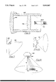
- FIG. 6 is a side elevation of the trunking shown in FIG. 3, toillustrate how the trunking may be mounted on a wall in a first fashion;
- FIG. 7 is a view similar to FIG. 6 but showing how the trunking may be mounted on a wall in a second fashion.
- FIG. 8 is a view to illustrate how the beam intensity from each lens unit may be varied.
- a lighting arrangement comprises a fibre optic cable 10 having an input end 12, and a plurality of output ends of tails 14.
- the input end 12 of the fibre optic cable is housed in a casing 16 containing a light source 18 and, in this example, a motor 20 arranged to drive a filter disc 22 having a plurality of segments of different colour so that light transmitted from the source 18, which is a white light source, will be coloured according to the angular position of the disc 22 in relation to the light source 18, as the said disc 22 as shown in FIG. 1 lies between the light source 18 and the end 12 of the fibre optic cable.
- the casing 16 will contain the additional components as may be required for the connection of the motor 20 and the source 18 to a suitable power supply connected via lines 24.
- lens units 26 At the tail ends 14 of the fibre optic cable are provided lens units 26 of which particular detail will be given hereinafter, but for the present it is to be noted that the lens units 26 are arranged to receive light issuing from the tail ends 14 of the fibre optic cable, and to focus such a light into individual beams 28.
- the beams 28 in FIG. 1 are shown as travelling in relatively random direction because in fact the individual lens units 26 are angularly adjustable so that the individual beams can be directed to a plurality of a spaced location to highlight articles located in such locations.
- the lighting arrangment shown in FIG. 1 is particularly adapted for the illumination of objects and articles which ar located at a relatively short distance from the lens units 26 i.e. of the order of 500 mm or less, and therefore the lens units 26 do in fact perform the same role as do the pin spot light sources referred to hereinbefore, but with considerable advantages as compared to such individual pin spot light sources.
- FIG. 3 shows in perspective the arrangement shown in FIG. 1.
- the casing 16 is shown clearly as is the fibre optic cable 10 and shown are two of the lens units 28.
- the lens units are each carried by plastic extruded plates 30 which are springingly received in a plastic extruded trunking bar 32 which contains a clip bar 34 which cooperate to hold the plates 30 in position.
- FIG. 3 also shows that a blanking panel 36 may be used for the appropriate postioning of the plates 30, but it should be mentioned that the plates 30 can be positioned at any location along the length of the trunking 32.
- the fibre optic cable 10 and the ends 14 of which one is shown in FIG. 3 are housed inside the trunking and therefore are out of site giving the assembly a particularly neat appearance. Nor do all of the ends 14 of the cable 10 need be directed to the same length of trunking 32, but as shown at 14A in FIG. 3, some of these ends may be directed to parallel or adjacent trunking assemblies having lens units 28. In particular, as shown in FIG. 2, there are two trunking assemblies 32 and 32A along each side 38 and 40 of the Y-shaped display case 42 shown in FIG. 2.
- FIG. 4 A detailed sectional view of each lens unit and its mounting is shown in FIG. 4, and the figure shows clearly the trunking bar 32 and the partition plate 30 of the lens unit. Additionally, the locking section 34 is shown, and it will be seen that it is held to the trunking 32 by means of ribs 40 on the inside of the trunking, and beadings 42 on the section 34, which are sprung into the ribs 40.
- the partition plate 30 is provided with parallel rails 44 which clip into position on holding flanges 46 on the trunking 32.
- the lens unit includes a spherical body 48 which fits in an aperture 50 in the plate 30, and a spring ring 52 which is sprung into position by locating behind a beading 54 on the plate 30 serves to create a spherical bearing for the body 48 so that it can swivel within a cone of adjustment in any direction and about the centre of the spherical body 48.
- the body 48 has a stepped bore 56 in the rear end of which is received a cap 58 having in its turn a bore 60, the bore 60 receiving the tail 14 of the fibre optic cable harness.
- a sleeve 62 has an enlarged end 64 which is slidable in the bore 56 and inside the sleeve is a first lens 66 and at the front end is provided a second lens 68.
- the optical arrangement is shown more clearly in FIG. 5, in which it will be seen that the lens 66 is fixed in position between the ends of the sleeve 62, whereas the lens 68 is in the form of a cap which fits over what is the front end of the sleeve 62.
- the lens 66 is omitted and only angle lens 68, which is a simple plastic lens, may be used.
- the end face 14A of the fibre optic tail 14 is shown, and this forms a light emitting face from which a cone of light issues onto the lens 66.
- the lens pair 66 and 68 focus the light and provide a narrow beam which is directed to an object or location to be illuminated as described previously herein.
- each lens unit comprising plate 30 with its rails 44, ring 52, body 48 and sleeve 62 can be inserted and removed in the trunking 32 as required depending upon how many units are to be carried by the trunking, and as many lengths of trunking as required are fitted to the display area such as a display case 42 shown in FIG. 2.
- the trunking may be provided with end plates which clip into the ends in order to close same to prevent ingress of dust or the like.
- FIG. 6 shows how the trunking 32 maybe mounted on a wall or other support surface 70 so that the main beam direction is horizontal, although the beam can be directed at any angle within the cone 72 illustrated, such cone having a 90° cone angle.
- the trunking is mounted at 45° relative to the position shown in FIG. 6 so that the main beam direction is at a downwardly inclined angle of 45°, but again the lens unit can be adjusted so that the beam lies within a cone 72 of 90° cone angle.
- FIG. 8 shows the arrangement wherein the beam mean direction is vertically downwards, and the figure also indicates how the area illuminated can be varied by sliding the sleeve 62 in and out of the bore 56 as indicated by arrow 74 in FIG. 4 and also in FIG. 8.
- the beam size can either be made large as indicated by reference 76 or small as indicated by numeral 78, or the size can be made anything in between the maximum and minimum as dictated by the position of the sleeve 62.
- the trunking 32 is shaped as illustrated in FIG. 4 in order to enable the trunking readily to be mounted at the angles described herein so that the main beam direction is horizontal, inclined downwardly at 45° or inclined upwardly at 45° or is vertically downwards or indeed vertically upwards when the trunking is mounted on a vertical or horizontal wall surfaces.
- the trunking may be connected to the wall surfaces simply by using fixing screws which pass through apertures in the trunking.
- the dimensions chosen for the particular embodiment provide that if a lens unit is located at 500 mm from a wall (dimension X in FIG. 8) the beam of light can be directed at any location within a circle of 1 meter diameter.
- the area of illumination can be varied by moving the sleeve as described herein and at a range of 500 mm, the lens unit will give a spot of light ranging from 150 mm dia. down to 50 mm dia. minimum, and as the spot of light becomes smaller, it of course becomes more intense, which makes the arrangement described particularly suitable for illuminating relatively small objects from a short distance.
- the range of lighting does however upon the ambient lighting conditions. In a shop window, the range would relative short because of the extraneous light, but in a dark environment a considerably greater range can be achieved which provides for dynamic lighting effects.
- the diameter of the spot of light can be varied between the order of 300 mm and 100 mm.
- the arrangement described has many advantages over the conventional pin spot illumination method.
- more individual lens units can be fitted into a small space. They can be as close as 40 mm and therefore 24 individual lens units can be located in a 1 meter length of trunking.
- the lens units remain cold since all the heat is generated in a light source which is positioned away from the display area, making the arrangement particularly suitable where heat sensitive subjects such as chocolates or delicate manuscripts are to be illuminated.
- the customer is protected from the hazard of heating of the glass which is usually associated with spot lighting in small display cabinets.
- the lighting effect created by the lens units can be varied to give interesting dynamic effects.
- the jewels can be made to sparkle and change colour.
- the arrangement described provides that the lens units are supported by a plastic trunking system which incorporates special channels for the management of the fibre optic cable, and provides a versatile means of mounting the pin points to suit many lighting applications. Adjustment of the beam intensity and beam angle can be effected simply by hand by grasping the sleeve 62 and manipulating same accordingly.
Abstract
Description
Claims (6)
Applications Claiming Priority (3)
| Application Number | Priority Date | Filing Date | Title |
|---|---|---|---|
| GB868626033A GB8626033D0 (en) | 1986-10-30 | 1986-10-30 | Lens assembly |
| GB8626033 | 1986-10-30 | ||
| SG103394A SG103394G (en) | 1986-10-30 | 1994-07-26 | Assemblies and apparatus for lighting especially spotlighting |
Publications (2)
| Publication Number | Publication Date |
|---|---|
| US5050047A true US5050047A (en) | 1991-09-17 |
| US5050047B1 US5050047B1 (en) | 2000-07-11 |
Family
ID=26291477
Family Applications (1)
| Application Number | Title | Priority Date | Filing Date |
|---|---|---|---|
| US07115134 Expired - Fee Related US5050047B1 (en) | 1986-10-30 | 1987-10-30 | Assemblies and apparatus for lighting especially spotlighting |
Country Status (4)
| Country | Link |
|---|---|
| US (1) | US5050047B1 (en) |
| EP (1) | EP0265892B1 (en) |
| HK (1) | HK136094A (en) |
| SG (1) | SG103394G (en) |
Cited By (47)
| Publication number | Priority date | Publication date | Assignee | Title |
|---|---|---|---|---|
| US5325272A (en) * | 1993-04-16 | 1994-06-28 | Miller Jack V | Fiber optic track lighting system |
| US5353786A (en) * | 1992-01-24 | 1994-10-11 | Wilk Peter J | Surgical lighting method |
| US5426572A (en) * | 1993-12-01 | 1995-06-20 | International Lighting Manufacturing Company | Light fixtures |
| US5430825A (en) * | 1994-06-28 | 1995-07-04 | Leaman; William M. | Fiber optic light assembly method |
| US5483427A (en) * | 1994-10-21 | 1996-01-09 | Dealey, Jr.; O. K. | Cargo area lighting system for trucks |
| USD380058S (en) * | 1995-08-21 | 1997-06-17 | Lighting Services, Inc. | Fiber optic light bar |
| US5678914A (en) * | 1995-11-13 | 1997-10-21 | Transmatic, Inc. | Cargo area lighting system for trucks |
| USD406279S (en) * | 1997-07-03 | 1999-03-02 | General Signal Corporation | Combination emergency lighting device and exit sign |
| US5907648A (en) * | 1997-08-15 | 1999-05-25 | Miller; Jack V. | Aimable-beam fiber-optic spotlight luminaire |
| US5999686A (en) * | 1997-11-14 | 1999-12-07 | Lightly Expressed, Ltd. | Fiber optic lighting system with lockable spot lights |
| US6007217A (en) * | 1998-05-01 | 1999-12-28 | Ledalite Architectural Products, Inc. | Luminaire assembly mounting system |
| US6019477A (en) * | 1997-07-03 | 2000-02-01 | Dual-Lite Inc. | Emergency lighting device |
| US6045242A (en) * | 1998-06-30 | 2000-04-04 | Dual-Lite Inc. | Lighting fixture |
| US6045250A (en) * | 1996-03-04 | 2000-04-04 | Simon; Jerome H. | Method and apparatus of controlling beam divergence and directionality |
| USD426334S (en) * | 1998-06-30 | 2000-06-06 | Dual-Lite Inc. | Emergency lighting fixture |
| US6082884A (en) * | 1998-02-27 | 2000-07-04 | Unison Fiber Optic Systems, L.L.C. | Adjustable fiber optic lighting fixture for individually adjusting the color, focal length and aim of the produced light and method |
| US6152586A (en) * | 1999-01-28 | 2000-11-28 | Transmatic, Inc. | Cargo area lighting system for trucks |
| US6220724B1 (en) * | 1998-03-03 | 2001-04-24 | Gunnar Krokeide | Device for realizing actively luminous illuminated route systems |
| WO2001088433A1 (en) * | 2000-05-17 | 2001-11-22 | Västra Götalands Läns Landsting | Lighting device |
| US6379027B1 (en) | 2000-03-30 | 2002-04-30 | Ruud Lighting, Inc. | Light-generating and beam-establishing device |
| US6508579B1 (en) | 2000-05-09 | 2003-01-21 | Alan J. Ruud | Lighting apparatus for illuminating well-defined limited areas |
| US6517216B1 (en) | 1999-09-17 | 2003-02-11 | Brightline, L.P. | Adjustable fluorescent lighting fixtures |
| DE19934037B4 (en) * | 1998-09-01 | 2004-10-28 | Prograph Graphische Produktionsgesellschaft Mbh | lighting device |
| US20050271345A1 (en) * | 2004-06-02 | 2005-12-08 | Laurier Roy | Fiber optic light bar |
| US20060002136A1 (en) * | 2004-06-30 | 2006-01-05 | Buelow Roger F Ii | Adjustable-aim light pipe fixture |
| US20060067089A1 (en) * | 2004-09-29 | 2006-03-30 | Luxam, Inc. | Lighting apparatus for a museum display case |
| US20070058369A1 (en) * | 2005-01-26 | 2007-03-15 | Parkyn William A | Linear lenses for LEDs |
| US20070100211A1 (en) * | 2005-11-02 | 2007-05-03 | Depuy Spine, Inc. | Illuminated surgical access system including a surgical access device and coupled light emitter |
| US20070147053A1 (en) * | 2005-12-23 | 2007-06-28 | Canlyte Inc. | Support Device |
| US20080030996A1 (en) * | 2006-08-07 | 2008-02-07 | Ming-Chih Chen | Reptile lamp having direction adjustable function |
| US20080106892A1 (en) * | 2006-09-21 | 2008-05-08 | Griffiths Terence P | Light fixture |
| US20080304252A1 (en) * | 2007-06-11 | 2008-12-11 | Sanyo Electric Co., Ltd. | Showcase |
| US20090244913A1 (en) * | 2008-03-31 | 2009-10-01 | Ronald Edward Anglikowski | Wall-Mountable Light Fixture Providing Light Having a Particular Directionality |
| US20090244897A1 (en) * | 2008-03-31 | 2009-10-01 | Ronald Edward Anglikowski | Light fixture with optional animate object detector and heat sink |
| US7673430B1 (en) | 2006-08-10 | 2010-03-09 | Koninklijke Philips Electronics, N.V | Recessed wall-wash staggered mounting system |
| US20110222268A1 (en) * | 2010-03-12 | 2011-09-15 | Dennis Pearson | Wall Mounted Aisle, Step and Corridor Light System |
| US20110228519A1 (en) * | 2010-03-19 | 2011-09-22 | Lumination Llc | Lighted display case having reduced glare |
| US20120120669A1 (en) * | 2010-11-16 | 2012-05-17 | Mcclellan Thomas David | Lighting system and swivel fixture with led assembly |
| US20140133157A1 (en) * | 2012-11-12 | 2014-05-15 | General Electric Company | Lighting assembly |
| DE202014101989U1 (en) * | 2014-04-28 | 2015-07-30 | Zumtobel Lighting Gmbh | Cover for the carrier assembly of a lighting system, as well as lighting system |
| US9310037B2 (en) | 2012-02-08 | 2016-04-12 | Brightline, Inc. | Motorized lighting fixture with motor and light dimming control |
| US9752739B2 (en) | 2011-08-29 | 2017-09-05 | Hubbell Incorporated | Emergency lighting assembly having heat conducting member |
| US10267968B2 (en) * | 2016-12-15 | 2019-04-23 | Tubemaster, Inc. | Lighting and communication system for confined space |
| JP2020035767A (en) * | 2017-11-06 | 2020-03-05 | 東芝ライテック株式会社 | Lighting fixture |
| US10625170B2 (en) * | 2017-03-09 | 2020-04-21 | Lumena Inc. | Immersive device |
| US11058961B2 (en) * | 2017-03-09 | 2021-07-13 | Kaleb Matson | Immersive device |
| US11486565B2 (en) * | 2019-03-21 | 2022-11-01 | Signify Holding B.V. | Adjustable light source holder, a directable spotlight and a manufacture method thereof |
Families Citing this family (7)
| Publication number | Priority date | Publication date | Assignee | Title |
|---|---|---|---|---|
| US4868718A (en) * | 1989-03-13 | 1989-09-19 | General Electric Company | Forward illumination lighting system for vehicles |
| DE4119975C2 (en) * | 1991-06-14 | 1993-11-04 | Swarovski & Co | SHOWCASE FOR EFFECT LIGHTING OF OBJECTS |
| DE4225433C2 (en) * | 1992-07-31 | 1994-10-06 | Siemens Ag | Magnetic resonance scanner with a light source |
| AT2222U1 (en) * | 1997-04-11 | 1998-06-25 | Swarovski & Co | LAMP |
| AT506521B1 (en) | 2008-02-22 | 2010-06-15 | Hierzer Andreas | LIGHTS PROFILE |
| US20120212932A1 (en) | 2009-08-13 | 2012-08-23 | Vincent Guenebaut | Spotlight |
| DE102012221454B4 (en) * | 2012-11-23 | 2022-06-23 | Zumtobel Lighting Gmbh | Luminaire with a luminaire housing that includes a profile element |
Citations (12)
| Publication number | Priority date | Publication date | Assignee | Title |
|---|---|---|---|---|
| US3278739A (en) * | 1964-01-02 | 1966-10-11 | Bausch & Lomb | Illuminator |
| US3645254A (en) * | 1970-04-17 | 1972-02-29 | Charles Burton | Surgical light |
| FR2128909A5 (en) * | 1971-03-08 | 1972-10-27 | Sreta | |
| FR2188099A1 (en) * | 1972-06-06 | 1974-01-18 | Kodak Pathe | |
| US3912918A (en) * | 1974-04-22 | 1975-10-14 | Designs For Vision | Light sources employing universally adjustable ball and socket joints |
| DE2814962A1 (en) * | 1978-04-06 | 1979-10-18 | Beco Beleuchtungstechnik W Jag | Lighting fitting using halogen lamps - has lamp with flexible optical to conduct light close to work surface |
| FR2431659A1 (en) * | 1978-07-19 | 1980-02-15 | Murakami Tatsuo | FIBER OPTICAL ILLUMINATION DEVICE |
| US4280122A (en) * | 1980-06-30 | 1981-07-21 | Dolan-Jenner Industries, Inc. | Optical fibers |
| US4329737A (en) * | 1979-07-26 | 1982-05-11 | Optische Werke G. Rodenstock | Light-emitting diode arrangement |
| DE3200938A1 (en) * | 1982-01-14 | 1983-07-21 | Laaber Faseroptik GmbH, 6090 Rüsselsheim | Fibre-optic multipoint lighting fixture having a variable focal length |
| US4729070A (en) * | 1986-05-12 | 1988-03-01 | David Chiu | Adjustable ring light |
| US4745525A (en) * | 1987-03-02 | 1988-05-17 | Sheehy Paul M | Lighted tailgate for pickup truck |
-
1987
- 1987-10-26 EP EP87115699A patent/EP0265892B1/en not_active Expired - Lifetime
- 1987-10-30 US US07115134 patent/US5050047B1/en not_active Expired - Fee Related
-
1994
- 1994-07-26 SG SG103394A patent/SG103394G/en unknown
- 1994-12-01 HK HK136094A patent/HK136094A/en not_active IP Right Cessation
Patent Citations (12)
| Publication number | Priority date | Publication date | Assignee | Title |
|---|---|---|---|---|
| US3278739A (en) * | 1964-01-02 | 1966-10-11 | Bausch & Lomb | Illuminator |
| US3645254A (en) * | 1970-04-17 | 1972-02-29 | Charles Burton | Surgical light |
| FR2128909A5 (en) * | 1971-03-08 | 1972-10-27 | Sreta | |
| FR2188099A1 (en) * | 1972-06-06 | 1974-01-18 | Kodak Pathe | |
| US3912918A (en) * | 1974-04-22 | 1975-10-14 | Designs For Vision | Light sources employing universally adjustable ball and socket joints |
| DE2814962A1 (en) * | 1978-04-06 | 1979-10-18 | Beco Beleuchtungstechnik W Jag | Lighting fitting using halogen lamps - has lamp with flexible optical to conduct light close to work surface |
| FR2431659A1 (en) * | 1978-07-19 | 1980-02-15 | Murakami Tatsuo | FIBER OPTICAL ILLUMINATION DEVICE |
| US4329737A (en) * | 1979-07-26 | 1982-05-11 | Optische Werke G. Rodenstock | Light-emitting diode arrangement |
| US4280122A (en) * | 1980-06-30 | 1981-07-21 | Dolan-Jenner Industries, Inc. | Optical fibers |
| DE3200938A1 (en) * | 1982-01-14 | 1983-07-21 | Laaber Faseroptik GmbH, 6090 Rüsselsheim | Fibre-optic multipoint lighting fixture having a variable focal length |
| US4729070A (en) * | 1986-05-12 | 1988-03-01 | David Chiu | Adjustable ring light |
| US4745525A (en) * | 1987-03-02 | 1988-05-17 | Sheehy Paul M | Lighted tailgate for pickup truck |
Cited By (77)
| Publication number | Priority date | Publication date | Assignee | Title |
|---|---|---|---|---|
| US5353786A (en) * | 1992-01-24 | 1994-10-11 | Wilk Peter J | Surgical lighting method |
| US5325272A (en) * | 1993-04-16 | 1994-06-28 | Miller Jack V | Fiber optic track lighting system |
| US5769529A (en) * | 1993-12-01 | 1998-06-23 | International Lighting Manufacturing Company | Light fixture |
| US5426572A (en) * | 1993-12-01 | 1995-06-20 | International Lighting Manufacturing Company | Light fixtures |
| US5430825A (en) * | 1994-06-28 | 1995-07-04 | Leaman; William M. | Fiber optic light assembly method |
| US5483427A (en) * | 1994-10-21 | 1996-01-09 | Dealey, Jr.; O. K. | Cargo area lighting system for trucks |
| US5573327A (en) * | 1994-10-21 | 1996-11-12 | Dealey, Jr.; O. K. | Cargo area lighting system for trucks |
| USD380058S (en) * | 1995-08-21 | 1997-06-17 | Lighting Services, Inc. | Fiber optic light bar |
| US5678914A (en) * | 1995-11-13 | 1997-10-21 | Transmatic, Inc. | Cargo area lighting system for trucks |
| US6045250A (en) * | 1996-03-04 | 2000-04-04 | Simon; Jerome H. | Method and apparatus of controlling beam divergence and directionality |
| USD406279S (en) * | 1997-07-03 | 1999-03-02 | General Signal Corporation | Combination emergency lighting device and exit sign |
| US6019477A (en) * | 1997-07-03 | 2000-02-01 | Dual-Lite Inc. | Emergency lighting device |
| US6280042B1 (en) | 1997-07-03 | 2001-08-28 | Dual-Lite Inc. | Emergency lighting device |
| US5907648A (en) * | 1997-08-15 | 1999-05-25 | Miller; Jack V. | Aimable-beam fiber-optic spotlight luminaire |
| US5999686A (en) * | 1997-11-14 | 1999-12-07 | Lightly Expressed, Ltd. | Fiber optic lighting system with lockable spot lights |
| US6082884A (en) * | 1998-02-27 | 2000-07-04 | Unison Fiber Optic Systems, L.L.C. | Adjustable fiber optic lighting fixture for individually adjusting the color, focal length and aim of the produced light and method |
| US6220724B1 (en) * | 1998-03-03 | 2001-04-24 | Gunnar Krokeide | Device for realizing actively luminous illuminated route systems |
| US6007217A (en) * | 1998-05-01 | 1999-12-28 | Ledalite Architectural Products, Inc. | Luminaire assembly mounting system |
| USD426334S (en) * | 1998-06-30 | 2000-06-06 | Dual-Lite Inc. | Emergency lighting fixture |
| US6045242A (en) * | 1998-06-30 | 2000-04-04 | Dual-Lite Inc. | Lighting fixture |
| DE19934037B4 (en) * | 1998-09-01 | 2004-10-28 | Prograph Graphische Produktionsgesellschaft Mbh | lighting device |
| US6152586A (en) * | 1999-01-28 | 2000-11-28 | Transmatic, Inc. | Cargo area lighting system for trucks |
| US6517216B1 (en) | 1999-09-17 | 2003-02-11 | Brightline, L.P. | Adjustable fluorescent lighting fixtures |
| US20030123252A1 (en) * | 1999-09-17 | 2003-07-03 | Cercone Samuel P. | Adjustable fluorescent lighting fixtures |
| US6893139B2 (en) | 1999-09-17 | 2005-05-17 | Samuel P. Cercone | Adjustable fluorescent lighting fixtures |
| US6379027B1 (en) | 2000-03-30 | 2002-04-30 | Ruud Lighting, Inc. | Light-generating and beam-establishing device |
| US6508579B1 (en) | 2000-05-09 | 2003-01-21 | Alan J. Ruud | Lighting apparatus for illuminating well-defined limited areas |
| WO2001088433A1 (en) * | 2000-05-17 | 2001-11-22 | Västra Götalands Läns Landsting | Lighting device |
| US20050271345A1 (en) * | 2004-06-02 | 2005-12-08 | Laurier Roy | Fiber optic light bar |
| US7110655B2 (en) | 2004-06-02 | 2006-09-19 | Laurier Roy | Fiber optic light bar |
| US7198398B2 (en) * | 2004-06-30 | 2007-04-03 | Fiberstars, Inc. | Adjustable-aim light pipe fixture |
| WO2006004834A2 (en) * | 2004-06-30 | 2006-01-12 | Fiberstars Incorporated | Adjustable-aim light pipe fixture |
| WO2006004834A3 (en) * | 2004-06-30 | 2007-01-18 | Fiberstars Inc | Adjustable-aim light pipe fixture |
| US20060002136A1 (en) * | 2004-06-30 | 2006-01-05 | Buelow Roger F Ii | Adjustable-aim light pipe fixture |
| US20060067089A1 (en) * | 2004-09-29 | 2006-03-30 | Luxam, Inc. | Lighting apparatus for a museum display case |
| US20070058369A1 (en) * | 2005-01-26 | 2007-03-15 | Parkyn William A | Linear lenses for LEDs |
| US7731395B2 (en) | 2005-01-26 | 2010-06-08 | Anthony International | Linear lenses for LEDs |
| US20070100211A1 (en) * | 2005-11-02 | 2007-05-03 | Depuy Spine, Inc. | Illuminated surgical access system including a surgical access device and coupled light emitter |
| US9005118B2 (en) | 2005-11-02 | 2015-04-14 | DePuy Synthes Products, LLC | Illuminated surgical access system including a surgical access device and coupled light emitter |
| US20110021882A1 (en) * | 2005-11-02 | 2011-01-27 | Sean Selover | Illuminated surgical access system including a surgical access device and coupled light emitter |
| US7874982B2 (en) * | 2005-11-02 | 2011-01-25 | Depuy Spine, Inc. | Illuminated surgical access system including a surgical access device and coupled light emitter |
| US20070147053A1 (en) * | 2005-12-23 | 2007-06-28 | Canlyte Inc. | Support Device |
| US8057077B2 (en) | 2005-12-23 | 2011-11-15 | Canlyte Inc. | Support device |
| US20080030996A1 (en) * | 2006-08-07 | 2008-02-07 | Ming-Chih Chen | Reptile lamp having direction adjustable function |
| US7673430B1 (en) | 2006-08-10 | 2010-03-09 | Koninklijke Philips Electronics, N.V | Recessed wall-wash staggered mounting system |
| US7856788B2 (en) | 2006-08-10 | 2010-12-28 | Genlyte Thomas Group Llc | Recessed wall-wash staggered mounting method |
| US7674010B2 (en) * | 2006-09-21 | 2010-03-09 | Hogarth Fine Art Limited | Light fixture having light emitting diode (LED) and resilient member |
| US20080106892A1 (en) * | 2006-09-21 | 2008-05-08 | Griffiths Terence P | Light fixture |
| US20080304252A1 (en) * | 2007-06-11 | 2008-12-11 | Sanyo Electric Co., Ltd. | Showcase |
| US7824057B2 (en) * | 2007-06-11 | 2010-11-02 | Sanyo Electric Co., Ltd. | Showcase |
| US8277071B2 (en) * | 2008-03-31 | 2012-10-02 | Heathco Llc | Wall-mountable light fixture providing light having a particular directionality |
| US7934854B2 (en) | 2008-03-31 | 2011-05-03 | Heathco Llc | Light fixture with optional animate object detector and heat sink |
| US20090244913A1 (en) * | 2008-03-31 | 2009-10-01 | Ronald Edward Anglikowski | Wall-Mountable Light Fixture Providing Light Having a Particular Directionality |
| US20090244897A1 (en) * | 2008-03-31 | 2009-10-01 | Ronald Edward Anglikowski | Light fixture with optional animate object detector and heat sink |
| US20110222268A1 (en) * | 2010-03-12 | 2011-09-15 | Dennis Pearson | Wall Mounted Aisle, Step and Corridor Light System |
| US8398276B2 (en) * | 2010-03-12 | 2013-03-19 | Tempo Industries, Llc | Wall mounted aisle, step and corridor light system |
| US20110228519A1 (en) * | 2010-03-19 | 2011-09-22 | Lumination Llc | Lighted display case having reduced glare |
| WO2011116372A1 (en) * | 2010-03-19 | 2011-09-22 | GE Lighting Solutions, LLC | Lighted display case having reduced glare |
| CN102869289A (en) * | 2010-03-19 | 2013-01-09 | Ge照明解决方案有限责任公司 | Lighted display case having reduced glare |
| US8434889B2 (en) | 2010-03-19 | 2013-05-07 | GE Lighting Solutions, LLC | Lighted display case having reduced glare |
| CN102869289B (en) * | 2010-03-19 | 2015-07-22 | Ge照明解决方案有限责任公司 | Lighted display case having reduced glare |
| US20120120669A1 (en) * | 2010-11-16 | 2012-05-17 | Mcclellan Thomas David | Lighting system and swivel fixture with led assembly |
| US9752739B2 (en) | 2011-08-29 | 2017-09-05 | Hubbell Incorporated | Emergency lighting assembly having heat conducting member |
| US11196282B2 (en) | 2011-08-29 | 2021-12-07 | Hubbell Incorporated | Emergency lighting assembly having heat conducting member |
| US10563831B2 (en) | 2011-08-29 | 2020-02-18 | Hubbell Incorporated | Emergency lighting assembly having heat conducting member |
| US9310037B2 (en) | 2012-02-08 | 2016-04-12 | Brightline, Inc. | Motorized lighting fixture with motor and light dimming control |
| US20140133157A1 (en) * | 2012-11-12 | 2014-05-15 | General Electric Company | Lighting assembly |
| US8814393B2 (en) * | 2012-11-12 | 2014-08-26 | General Electric Company | Lighting assembly |
| DE202014101989U1 (en) * | 2014-04-28 | 2015-07-30 | Zumtobel Lighting Gmbh | Cover for the carrier assembly of a lighting system, as well as lighting system |
| CN106164570A (en) * | 2014-04-28 | 2016-11-23 | 宗拓贝尔照明器材有限公司 | The top cover of load carrier and luminous zone system for luminous zone system |
| US20170089553A1 (en) * | 2014-04-28 | 2017-03-30 | Zumtobel Lighting Gmbh | Cover for the Support Arrangement of a Strip Light System and Strip Light System |
| US10330289B2 (en) * | 2014-04-28 | 2019-06-25 | Zumtobel Lighting Gmbh | Cover for the support arrangement of a strip light system and strip light system |
| US10267968B2 (en) * | 2016-12-15 | 2019-04-23 | Tubemaster, Inc. | Lighting and communication system for confined space |
| US10625170B2 (en) * | 2017-03-09 | 2020-04-21 | Lumena Inc. | Immersive device |
| US11058961B2 (en) * | 2017-03-09 | 2021-07-13 | Kaleb Matson | Immersive device |
| JP2020035767A (en) * | 2017-11-06 | 2020-03-05 | 東芝ライテック株式会社 | Lighting fixture |
| US11486565B2 (en) * | 2019-03-21 | 2022-11-01 | Signify Holding B.V. | Adjustable light source holder, a directable spotlight and a manufacture method thereof |
Also Published As
| Publication number | Publication date |
|---|---|
| SG103394G (en) | 1995-03-17 |
| HK136094A (en) | 1994-12-09 |
| US5050047B1 (en) | 2000-07-11 |
| EP0265892A1 (en) | 1988-05-04 |
| EP0265892B1 (en) | 1991-06-05 |
Similar Documents
| Publication | Publication Date | Title |
|---|---|---|
| US5050047A (en) | Assemblies and apparatus for lighting especially spotlighting | |
| ES2118943T3 (en) | EXHIBITION SHOWCASE WITH LIGHTING SYSTEM FOR LENSES. | |
| DK0732888T3 (en) | Exhibition cabinet with lens lighting system | |
| US5558421A (en) | Decorative fiber optic lamp | |
| TW315023U (en) | Marker apparatus | |
| KR0184258B1 (en) | Muliple cavity light fixture | |
| CA2031118A1 (en) | Direction dependent line light source | |
| US2493991A (en) | Ornamental illuminated device | |
| AU5771094A (en) | Ambient condition detector with high intensity strobe light | |
| US4761004A (en) | Infinity mirror display | |
| CA1309074C (en) | Assemblies and apparatus for lighting especially spotlighting | |
| EP0843296B1 (en) | Traffic light device made of lighting devices situated on the ground | |
| US6205282B1 (en) | Fiber-optic device for illuminating a light permeable information-bearing medium, such as a traffic, information or advertising sign | |
| FR2705435B1 (en) | Lighting source arrangement with optical fiber and adjustable light beam. | |
| DE4305208C2 (en) | Illuminated showcase | |
| US2210391A (en) | Illuminating system | |
| FR2534795A1 (en) | Lighting device, in particular for shop display windows or exhibition rooms, as well as for living accommodation. | |
| ES2040349T3 (en) | MICROSCOPE VIEWING PROVISIONS. | |
| JP3005920U (en) | Rainbow projection illuminator | |
| US20230026590A1 (en) | Illumination device, luminaire and refrigerator | |
| US3630618A (en) | Bearing inspection instrument | |
| DE19905483C2 (en) | display rack | |
| JPS627178Y2 (en) | ||
| FR2400743A1 (en) | Fibre optics advertising display panel - uses single 24 volts lamp and translucid glass or plastics light amplifying plaques | |
| JPH0741030Y2 (en) | Display body for exhibition |
Legal Events
| Date | Code | Title | Description |
|---|---|---|---|
| AS | Assignment |
Owner name: MOORE, STUART L., 128 PRINCE STREET, NEW YORK, NEW Free format text: ASSIGNMENT OF ASSIGNORS INTEREST.;ASSIGNOR:VINER, PETER;REEL/FRAME:005640/0909 Effective date: 19910123 |
|
| FEPP | Fee payment procedure |
Free format text: PAYOR NUMBER ASSIGNED (ORIGINAL EVENT CODE: ASPN); ENTITY STATUS OF PATENT OWNER: SMALL ENTITY |
|
| FPAY | Fee payment |
Year of fee payment: 4 |
|
| RR | Request for reexamination filed |
Effective date: 19950802 |
|
| FPAY | Fee payment |
Year of fee payment: 8 |
|
| B1 | Reexamination certificate first reexamination |
Free format text: CLAIM 1 IS CANCELLED. CLAIMS 2, 4 AND 5 ARE DETERMINED TO BE PATENTABLE AS AMENDED. CLAIMS 3 AND 6, DEPENDENT ON AN AMENDED CLAIM, ARE DETERMINED TO BE PATENTABLE. NEW CLAIM 7 IS ADDED AND DETERMINED TO BE PATENTABLE. |
|
| REMI | Maintenance fee reminder mailed | ||
| LAPS | Lapse for failure to pay maintenance fees | ||
| STCH | Information on status: patent discontinuation |
Free format text: PATENT EXPIRED DUE TO NONPAYMENT OF MAINTENANCE FEES UNDER 37 CFR 1.362 |
|
| FP | Lapsed due to failure to pay maintenance fee |
Effective date: 20030917 |