US5023934A - Apparatus and method for communication of visual graphic data with radio subcarrier frequencies - Google Patents
Apparatus and method for communication of visual graphic data with radio subcarrier frequencies Download PDFInfo
- Publication number
- US5023934A US5023934A US07/547,521 US54752190A US5023934A US 5023934 A US5023934 A US 5023934A US 54752190 A US54752190 A US 54752190A US 5023934 A US5023934 A US 5023934A
- Authority
- US
- United States
- Prior art keywords
- data
- receiver
- transmission
- display
- post
- Prior art date
- Legal status (The legal status is an assumption and is not a legal conclusion. Google has not performed a legal analysis and makes no representation as to the accuracy of the status listed.)
- Expired - Lifetime
Links
- 230000000007 visual effect Effects 0.000 title claims abstract description 28
- 238000004891 communication Methods 0.000 title claims abstract description 24
- 238000000034 method Methods 0.000 title claims description 42
- 238000012545 processing Methods 0.000 claims description 45
- 230000005540 biological transmission Effects 0.000 claims description 41
- 239000000835 fiber Substances 0.000 claims description 7
- 238000005056 compaction Methods 0.000 claims description 3
- 238000012937 correction Methods 0.000 claims description 3
- 238000004364 calculation method Methods 0.000 claims 2
- 238000001514 detection method Methods 0.000 claims 2
- 230000006870 function Effects 0.000 abstract description 8
- 238000012544 monitoring process Methods 0.000 abstract description 6
- 238000013475 authorization Methods 0.000 abstract description 3
- 238000006243 chemical reaction Methods 0.000 description 5
- 239000003086 colorant Substances 0.000 description 5
- 238000010586 diagram Methods 0.000 description 5
- 238000001556 precipitation Methods 0.000 description 4
- 238000007726 management method Methods 0.000 description 3
- 238000012986 modification Methods 0.000 description 3
- 230000004048 modification Effects 0.000 description 3
- 230000008569 process Effects 0.000 description 3
- 230000003068 static effect Effects 0.000 description 3
- 230000001360 synchronised effect Effects 0.000 description 3
- 230000008901 benefit Effects 0.000 description 2
- 230000000737 periodic effect Effects 0.000 description 2
- 230000002093 peripheral effect Effects 0.000 description 2
- 101100400452 Caenorhabditis elegans map-2 gene Proteins 0.000 description 1
- 101150064138 MAP1 gene Proteins 0.000 description 1
- 230000009471 action Effects 0.000 description 1
- 230000033228 biological regulation Effects 0.000 description 1
- 230000008859 change Effects 0.000 description 1
- 238000013497 data interchange Methods 0.000 description 1
- 230000001934 delay Effects 0.000 description 1
- 238000011161 development Methods 0.000 description 1
- 239000000284 extract Substances 0.000 description 1
- 230000006872 improvement Effects 0.000 description 1
- 238000009434 installation Methods 0.000 description 1
- 238000011835 investigation Methods 0.000 description 1
- 239000011159 matrix material Substances 0.000 description 1
- 230000010363 phase shift Effects 0.000 description 1
- 238000003825 pressing Methods 0.000 description 1
- 238000012913 prioritisation Methods 0.000 description 1
- 230000009467 reduction Effects 0.000 description 1
- 238000005549 size reduction Methods 0.000 description 1
- 230000005236 sound signal Effects 0.000 description 1
- 230000001629 suppression Effects 0.000 description 1
Images


Classifications
-
- H—ELECTRICITY
- H04—ELECTRIC COMMUNICATION TECHNIQUE
- H04B—TRANSMISSION
- H04B7/00—Radio transmission systems, i.e. using radiation field
- H04B7/24—Radio transmission systems, i.e. using radiation field for communication between two or more posts
- H04B7/26—Radio transmission systems, i.e. using radiation field for communication between two or more posts at least one of which is mobile
-
- H—ELECTRICITY
- H04—ELECTRIC COMMUNICATION TECHNIQUE
- H04B—TRANSMISSION
- H04B7/00—Radio transmission systems, i.e. using radiation field
- H04B7/14—Relay systems
- H04B7/15—Active relay systems
- H04B7/185—Space-based or airborne stations; Stations for satellite systems
- H04B7/18502—Airborne stations
- H04B7/18506—Communications with or from aircraft, i.e. aeronautical mobile service
Definitions
- SCA subsidiary communications authorization
- FSTV fast scan television
- analog data is transmitted.
- An advantage of these analog transmissions is that they do not require the features of digitized graphics, such as addressability of points on a display screen.
- a disadvantage, however, is that they do not permit processing by the user.
- NWS National Weather Service
- U.S. Pat. No. 4,347,618 discloses a system for providing NWS service data to various stationary receiving units, such as TV stations or airline operations facilities.
- the patent describes the Weather Bureau Radar Remote equipment used at the NWS locations to transmit NWS data by telephone lines.
- NWS data A common purpose of transmitting NWS data is for television broadcast.
- NWS radar scope is scanned by a television type camera.
- the data is transmitted over a telephone line to the television station where it is received and stored in an electronic memory. This memory is then electronically scanned to form a television picture for broadcast.
- the NWS video information is digitized and stored in an electronic memory.
- the contents of that memory are transmitted by telephone line to the television station.
- the data is there stored in another electronic memory, where only those signals necessary to form a television-compatible signal are extracted.
- a characteristic of television broadcasting is that it requires a greater bandwidth than other radiotelephonic communication.
- the weather communication systems described above which broadcast to the user by means of television video signals, use television rather than radio receivers.
- U.S. Pat. No. 3,080,556 discloses a system for communicating picture information, which requires a wide frequency range, over a standard voice channel.
- the invention derives an electronic signal in a relatively narrow bandwidth by using a slow-scan spiral sweep on the face of a cathode ray tube.
- the signal is heterodyned into a radio frequency carrier, which may be amplitude or frequency modulated.
- a conventional demodulator system is used to filter the radio frequency and cancel the sweep signal to leave only the video signal.
- the video signal is not digitized. This means that the video is displayed "as transmitted" and no data processing at the remote receiving unit is accomplished.
- the microprocessor was used only as a means of storage and for printing to a dot matrix printer.
- the equipment was large in size. The need for size reduction, visual CRT display, tuning, and noise reduction capabilities was recognized but not implemented.
- This feasibility study is disclosed in a report entitled "An Experimental Investigation of the Efficacy of Automated Weather Data Transmission to Aircraft in Flight," by Richard H. McFarland, dated 1982, available through the National Technical Information Service.
- An object of the invention is to provide a system for transmitting digitized video graphics signals via subcarrier radio frequencies.
- Another object of the invention is to provide a system for transmitting real time information to remote receivers. Users of the system have receiving units that create a visual display of weather information.
- Another object of the invention is to provide real time information from different sites as the user travels from place to place.
- the transmission is by radio rather than telephonic.
- Another object of the invention is to provide weather information to stationary or non stationary users.
- This information may originate from designated sources, such as NWS radar sites.
- Another object of the invention is to provide a system that permits real time weather monitoring across as large a geographical area as is covered by information gathering radar.
- a network of conventional FM stations capable of SCA broadcasting, participate in the system so that as a mobile receiver moves from the range of one FM station, it will enter the range of another.
- a tunable receiver permits the user to vary the FM frequency that is desired to be received.
- Another object of the invention is to provide a receiver having a built in modem so that its input is analog, audio data and its output is TTL data.
- Another object of the invention is to provide weather information that can be displayed on a conventional television display.
- Another object of the invention is to provide visual weather information that is transmitted to the user at voice and data frequencies rather than at conventional television frequencies.
- Another object of the invention is to permit a visual display that will be displayed even if the receiver is turned off.
- Another object of the invention is to permit data processing, controllable by the user at the receiving unit, of information transmitted by secondary carrier broadcasts.
- Another object of the invention is to permit information from other sources, such as LORAN, to be incorporated and displayed at mobile receiving units.
- Another object of the invention is to provide weather information that is automatically updated as weather conditions change.
- Another object of the invention is maintain historical weather data and permit the user to determine the movement and development of weather conditions.
- Another object of the invention is to provide error checking and error correction of incoming weather data.
- FIG. 1 is a block diagram of an overview of the invention as used for real time monitoring of weather information by a remote non-stationary user.
- FIG. 2 is a block diagram of the equipment used at the FM station site.
- FIG. 3 is a block diagram of the remote receiving unit.
- FIGS. 4a and 4b are front views of the front panel and controls for the receiving unit shown in FIG. 3.
- FIG. 5 is a block diagram of the receiver shown in FIG. 3.
- FIG. 6 is a block diagram of the computer shown in FIG. 3.
- FIG. 7 is a flow chart of the power on procedure controlling the computer shown in FIG. 6.
- FIG. 8 is a flow chart of the system's main program procedure.
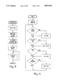
- FIG. 9 is a flow chart of the system's DoEnd procedure.
- FIG. 10 is a flow chart of the system's DoHistory procedure.
- FIG. 11 is a flow chart of the system's ExecKey procedure.
- FIG. 12 is a flow chart of the system's DoAids procedure.
- FIG. 13 is a flow chart of the system's PixIt procedure.
- FIG. 14 is a flow chart of the system's ColorIt procedure.
- FIG. 15 is a flow chart of the system's ColorPix procedure.
- FIG. 16 is a flow chart of the system's IRQ interrupt.
- FIG. 17 is a flow chart of the system's LineEqual procedure.
- FIG. 18 is a flow chart of the system's FIRQ interrupt.
- the invention is used for real time monitoring of weather information by non stationary users.
- the user's receiving and displaying equipment is installed on a vehicle, such as an airplane or boat.
- a vehicle such as an airplane or boat.
- this application includes features of the invention, such as a tunability of the receiver, that may not be necessary for other applications.
- the user may be stationary, such as at a facility that is weather sensitive, such as a computer processing site or an amusement park.
- an FM station is designated to participate in the system.
- Such stations are capable of broadcasting SCA signals, which are multiplexed on the main channel by frequency modulation of subcarriers.
- Detailed standards for such transmissions are in ⁇ 73.319 of the FCC Rules and Regulations.
- there are a network of FM stations each generally having 100,000 watts of power, giving the signal a reach of up to 200 miles at altitude.
- the FM station is capable of transmitting SCA transmissions at 92 kilocycles off the main carrier.
- FIG. 1 is an overview of the communications links of a data picture from its origin at a radar receiving site to an FM station and then to a remote receiving unit. NWS radars are used to gather precipitation data. There are then two transmission steps, which connect three locations remote from each other.
- the first transmission step is a telephonic transmission between the originating site and an FM station.
- the FM station the data is received, processed, and transmitted by FM site system 200.
- the second transmission step is an FM broadcast from the FM station to the user's remote receiving unit 300.
- the data begins as analog, radial scan, data.
- the data is then digitized for purposes of transmission to the FM site.
- FM site system 200 converts it to raster scan, rather than radial, format.
- a modem converts it to audio analog data, which then modulates the FM subcarrier signal.
- the data is transmitted by radio in a audio frequency shift keying format (AFSK).
- Audio frequency shift keying (AFSK) is a form of frequency modulation in which two states of a signal are transmitted as two separate audio frequencies. It is used for digital data because a predetermined audio frequency may be turned on and off by the transmitting modem as it sends a one or zero.
- the data is received by a tunable receiver, and then digitized by a microcomputer.
- the telephonic transmission step is via a continuous dataline, namely a 2400 bits per second (bps) telephone link using Synchronous Data Link Control ("SDLC").
- SDLC Synchronous Data Link Control
- This is a bit-oriented protocol, developed by the IBM Corporation, in which all information fields are 8 bits long. Information is sent by frames and within each frame are fields having specific functions. A message synchronization indicator, or flag, is generated by a hardware circuit. Other circuits prevent data from being transmitted from having the same pattern as the flag.
- This protocol and others functionally equivalent are well known in the art.
- the form of the data is digital in the sense that each pixel displayed at the radar site is transmitted as an 8-bit digital word. The digital words are transmitted in radial arcs, with a revolution of 360 degrees required to make up a complete map.
- FIG. 2 shows the equipment used at the FM station site.
- Digital graphics processor 210 receives the NWS data, which is in radial arc format. It converts this data to raster format and adds geophysical information, such as geographic boundaries and VOR references.
- the radial arc equipment used to transmit the data from the NWS site and the digital graphics processor 210 used to receive the data at the FM station is manufactured by Alden Electronics, Inc.
- digital graphics processor 210 An important function of digital graphics processor 210 is compaction of radar data. Radar data for a complete map has 320 pixels per line, with 240 lines. As received by digital graphics processor 210, the data requires a substantial amount of storage as well as transmission time. To reduce the amount of data required to be transmitted, digital graphics processor 210 executes a program using run line encoding to reduce the amount of data for each map. The program first counts the number of contiguous pixels of one color for each line. When a each new color begins on a line, the program begins a new count. For example, the first 20 pixels of a line might be: 5 blue, 11 yellow, 4 red. Rather than 20 bytes, only 3 bytes are required to be transmitted. In each of these 3 bytes, the first 3 bits contain the color.
- the fourth bit designates the type of map delivered from digital graphics processor 210.
- the next 4 bits permit up to 16 pixels of a single color to be designated.
- the last 4 bits of each of the 3 required bytes would be, in binary, 0101, 1011, and 0100, respectively.
- one byte is required for every 16 continuous pixels.
- 2 bytes are required for every 16 continuous pixels.
- Each of the 240 lines is compacted in this manner.
- Conversion interface 220 is a standard parallel-to-serial converter buffer box, which is commercially available. As shown in FIG. 2, the components are parallel input/output 222, buffer 226, and serial input/output 228, and depending on the type of buffer box, a CPU 224 may also be included.
- the data is converted from Centronics parallel format to serial format conforming to the RS-232 C standard.
- This is the standard of the Electronics Industries Association, and its proper name is "Interface Between Data Terminal Equipment and Data Communication Equipment Employing Serial Binary Data Interchange".
- the transmission rate from conversion interface 220 to format and schedule computer 230 is 1200 bps.
- the data out of digital graphics processor 210 has a specific format, in hexidecimal code, that is maintained for purposes of processing at the receiving unit 300.
- Each header begins with 00 FF.
- the next character is a control code, such as to indicate whether a map is beginning, ending, or in process.
- 05 indicates that a new map is beginning and 13 indicates that a map is complete.
- the code is 00 FF 05.
- Eight bytes follow, which may contain selected information, such as the time and date.
- there are 240 map lines each line having the code 00 FF 04 [ln], where ln is the line number. After 240 lines, the code is 00 FF 13 13, which signals the end of a map.
- control codes and others are maintained during radio transmission for purposes of processing the data at the receiving unit 300.
- Table 1 lists these control codes and gives a brief description of the data they identify:
- Format and schedule computer 230 is a standard microcomputer, and in the preferred embodiment is a compatible with or is an IBM PC, manufactured by the IBM Corporation.
- format and schedule computer 230 saves data comprising a complete map, or frame.
- a designated number of frames are saved in this manner. After the designated number of frames are saved, when a new period begins, a new frame is saved and the oldes frame is deleted. In the preferred embodiment, the period is 30 minutes and the designated number of frames to be saved is four. A time window is provided within each 30-minute period to ensure that a new historical map is saved. Thus, a two-hour history, comprised of four historical maps, is recorded. Table 1 shows the hex codes used to identify the start of the four radar history maps and the history data end.
- format and schedule computer 230 Another important part of format and schedule computer 230 is programming that schedules the sending of one real time map and four historical maps at periodic intervals. Thus, each transmission includes one "real time” map and 4 historical maps. The data referred to as "real time” is actually about 4 to 7 minutes behind because of transmission delays.
- Format and schedule computer 360 also is comprised of programming that further compacts the 4 historical maps. This is accomplished with a prioritization algorithm. Colors are prioritized into levels of intensity. In the preferred embodiment, there are 6 colors, or levels 1-6, and a level for geopolitical boundaries. The algorithm first selects an area of the map to be displayed, which, in the preferred embodiment, begins at row 24. Within this reduced frame, a small area is selected, which, in the preferred embodiment, is 3 rows down and 2 pixels across, making a square of 6 pixels. The algorithm then selects the highest color level in that 6-pixel square. Boundaries are a high level and are stripped. The 6 colors are prioritized to 4 colors. The selection routine is described below:
- the data passes to an SCA subcarrier modulator 240, where the data modulates a subcarrier signal, thereby converting the digital codes into signals that can be broadcast by radio.
- Modulator 240 delivers a signal at 92 kilohertz to FM transmitter 250.
- the data is transmitted one line at a time at a rate of 1200 bps. In the preferred embodiment, approximately 90 seconds are required to transmit one frame. This time period varies according to how much information is in each map. Each time a new map is transmitted, the four historical maps are also transmitted.
- receiving unit 300 can be illustrated as four basic blocks: antenna 310, receiver 320, computer 360, and display 390. These units can be portable, for example by being mounted in an instrument panel or carried as a hand portable unit.
- Antenna 310 picks up the subcarrier signal.
- antenna 310 is an FM antenna, although an existing antenna, such as a VOR antenna on an aircraft, may be used.
- receiving unit 300 is specially designed to be small in size, which facilitates its mobility.
- receiver 320, computer 360, and display 390 may be conveniently installed in an avionics instrumentation stack.
- Display 390 is a conventional CRT display. It displays varying degrees of green, yellow, tan, and red using the VIP standard, according to the intensity of the storm. There are six levels of intensity each represented by a different color.
- the screen size of display 390 is 192 by 256 pixels.
- FIGS. 4a and 4b show the control panels of receiver 320 and computer 360, respectively.
- Power is supplied from a standard DC source at 12 volts, and is controlled by means of switch 322 on control panel 321 of receiver 320 and by switch 362 on control panel 361 of computer 360.
- Power indicator lights 323 and 363 inform the user whether power is being delivered.
- Receiver control panel 321 also includes a carrier detect light 324 and a data light 325 to indicate whether a carrier signal is being detected and whether data is being transmitted. Receiver control panel 321 also includes a toggle switch that permits the user to vary the frequency to which receiver 320 is tuned. A conventional seven-segment, four-digit, LED display 327 displays the channel to which receiver 300 is tuned.
- Computer control panel 361 also includes four selection keys 364-367 and a cursor key 368.
- a first selection key 364 is a shift key, which permits the other three selection keys to have two functions, depending on the state of the shift key.
- a second selection key 365 permits the operator to view either historical weather data, or other types of data such as cloud cover that may be added as an improvement to the invention.
- a third selection key 366 permits the operator to zoom in or out of a screen or to call navigational programming procedures.
- a fourth selection key 367 permits the user to mark points on the map or to strip levels of color on display 390. By using these keys, the display may be zoomed in or out, scrolled, viewed in a time lapse historical sequence, or levels of precipitation may be wiped away.
- Cursor key 368 permits the user to move a cursor on the screen and to scroll the display. Scrolling is provided when a complete map is larger than what can be displayed on display 390. In the preferred embodiment, an entire map is 240 by 320 pixels, which is larger than the 192 by 256 pixel size of display 390. Thus, not all of a complete map can be viewed at once. If the user moves the cursor toward a boundary of the display 390, a new window will be displayed and the screen will refresh with a new map. This scrolling feature is provided for both color and monochrome map types, as explained below in connection with the appropriate system programming procedures.
- receiver 320 and computer 360 are made of a number of components. For purposes of describing the preferred embodiment, several commercially available components are identified below by manufacturer and number, but other components similar in function may be substituted.
- receiver 320 is a tunable SCA subcarrier receiver. It is designed to filter a 92 kilohertz subcarrier component contained in a main audio carrier signal.
- Intermediate frequency (“IF") filters 522 and 526 first obtain a signal at 10.7 megahertz.
- a subcarrier filter 534 then obtains a 92 kilohertz signal.
- Receiver 320 is designed to have a minimum of noise, as well as being small in size.
- the entire receiver circuit is mounted on a single printed circuit board (not shown).
- Receiver 320 is shielded by means of its container (not shown) and by making the printed circuit board (not shown) multi-layered.
- This printed circuit board has four planes, with circuitry on planes 2 and 3.
- a conductive ground mesh is laid on planes 1 and 4.
- tuner 510 receives signals from antenna 310, and is tunable from 87.9 to 107.9 megacycles.
- Tuner 510 operates in conjunction with the local oscillator, frequency divider 512 and frequency synthesizer 514.
- the local oscillator 512 is tuned by a control signal from the frequency synthesizer 514.
- Frequency selector 516 permits the operator to select a frequency, according to the radio station whose signal is sought to be received.
- Frequency synthesizer 514 receives this information from frequency selector 516 and sends control signals to frequency divider 512, which then modifies the local oscillator output. From these inputs, frequency divider 512 delivers a signal to frequency synthesizer 514. After analyzing the this signal, frequency synthesizer 514 then delivers a control voltage to the local oscillator.
- frequency synthesizer 514 is combined in a single integrated circuit with display controller 518.
- the signals generated by frequency synthesizer 514 are converted by display controller 518 to standard seven-segment LED display signals. These signals pass to display drivers 520, which amplify the signals to turn on the LED lights in LED display 327.
- the component used in the preferred embodiment is the uPD1701, manufactured by the NEC Corporation.
- the signal is filtered by a first IF filter 522.
- the signal then passes through a first buffer amplifier 524 and a second IF filter 526.
- a third IF filter and second buffer amplifier are added in the preferred embodiment, thereby passing the signal through three filter stages rather than two, prior to being delivered to IF amplifier 528.
- the IF filter and amplifier components of receiver 320 perform single conversion superheterodyne techniques.
- a 10.7 megacycle signal is selected, having a width of plus or minus 200 kilocycles.
- fm detector 530 is a quadrature detector 530.
- the significant features of detector 530, as opposed to some other forms of detectors are noise suppression, good signal quality, and a relatively wide bandwidth.
- a DC gain control signal proportional to the amplitude of the RF component is fed back to tuner 510.
- Feedback filter 532 is a tuned tank circuit, used to create a phase shift of 10.7 megahertz IF signal proportional to the frequency shift of the 10.7 megahertz signal. This signal shifted an additional 90 degrees is then multiplied with the original 10.7 megahertz signal to create a signal proportional to the frequency shift of the main carrier.
- the signal passes from detector 530 to SCA subcarrier filter 534, which extracts the 92 kilohertz signals, with a width of plus or minus 6 kilohertz.
- the signal then passes to subcarrier amplifier 535 and quadrature detector 536.
- the signal passes to FSK demodulator 538 and digital data generator 540. These components convert the signal from frequency shift keyed form to digital codes. Control signals from these components determine whether the carrier detect light 324 and data light 325 on front panel 321 will be "on".
- the digitized data is then transmitted to computer 360 by means of fiber optics light transmitter 542.
- This receiver-to-computer transmission means is desirable because it is immune to common mode interferences.
- a standard fiber optic cable 541 carries data from receiver 320 to computer 360.
- Computer 360 is shown in further detail in FIG. 6. It is microprocessor-based, microprocessor 610 having 64 kilobytes of linear addressing capability, with a memory management unit giving it 96 kilobytes of addressability.
- microprocessor 610 is a commercially available unit, such as the MC6809 8-bit microprocessor manufactured by Motorola, Inc.
- Computer 360 includes conventional data and address busses.
- An address decoder 612 interprets address codes and delivers the stored information.
- Computer 360 also includes a memory system comprised of various memory devices, whose use depends on whether the memory is to be read only or random access and whether it is to be dynamic or static. This is a multilevel memory structure, in which a virtual or cache memory holds portions of the programming and data as needed, with a secondary memory for storing the remainder of the programming and data.
- MMU 614 This memory system includes a memory management unit (“MMU”) 614, whose main function is to control address lines for the video display controller and microprocessor and permits both to have direct memory access.
- MMU 614 is a conventional unit, comprised of a number of well-known components (not shown).
- One such component is a synchronous address multiplexer (“SAM”) chip, which in the preferred embodiment is an MC6883 chip manufactured by Motorola, Inc.
- SAM synchronous address multiplexer
- Additional components are typical of conventional microcomputers, and include commercially available chips having the reference numbers 74LS156, 74HC00, 74HC541, and 74HC53, which create various control signals.
- the memory devices include dynamic and static memory and read only memory. Dynamic memory 616 stores bits in the form of electric charges.
- dynamic memory 616 is capable of storing 64 kilobytes of data.
- Static memory 618 stores bits in flip-flops, and has a capacity of 8 kilobytes.
- the preferred embodiment also includes erasable programmable read only memory (“EPROM”) in which the system programming is stored.
- EPROM erasable programmable read only memory
- an EPROM 620 has a capacity of 16 kilobytes
- an electrically erasable and programable read only memory (“EEPROM”) 622 has a capacity of 512 bytes.
- EEPROM 622 An advantage of EEPROM 622 is that it can be programmed and erased while still within the circuit of the system. This permits the system programming to be updated and modified in circuit and permits a remote receiver to be addressable by code so that record keeping can be maintained on a per user basis.
- Computer 360 receives incoming data from receiver 320 by means of fiber optics data detector 624. The data then passes to asynchronous serial interface (ASI) 626, which is in communication with microprocessor 610. ASI 626 provides data formatting and control to interface serial asynchronous data communications information to bus organized systems. ASI 626 is a commercially available component, commonly referred to as an asynchronous communications interface adapter.
- ASI asynchronous serial interface
- Parallel interface 628 is also in communication with microprocessor 610. It provides the means for interfacing peripheral equipment to microprocessor 610. It is a commercially available component such as the MC6821, manufactured by Motorola, Inc.
- VDC video display controller
- EEPROM 622 EEPROM 622
- VDC 630 reads data from the memory devices and generates a graphic display on display 390.
- VDC 630 is a commercially available device, such as the MC6847 manufactured by Motorola, Inc.
- the circuits of both receiver 320 and computer 360 include voltage regulators 544 and 632. Conventional devices may be used for this purpose to prevent changes in operating voltage from causing false signals, which may interfere with operation of component parts.
- the user simply turns power on to receiver 320 and computer 360 by switching the appropriate power switches on front panels 321 and 361.
- the user then tunes receiver 320 to an appropriate channel, using frequency selector 326. Maps are then displayed and automatically updated on display 390 as determined by the system programming.
- the user may also select various modifications to the display by executing various programming procedures. All user input is through the selection keys 364-367 and cursor key 368.
- FIGS. 7 through 18 The system programming is illustrated in FIGS. 7 through 18.
- the programming is written in the C language.
- Each C program is comprised of one or more procedures, which are illustrated in FIGS. 8 through 15 and FIG. 17.
- One procedure may call another, and procedures may be nested.
- the system programming is interrupt driven, meaning that the critical procedures that synchronize operation are selected by the interrupts.
- FIGS. 16 and 18 illustrate the two interrupts. As explained below, one interrupt is initiated by incoming data, and the other by a field sink from VDC 630.
- Map.type is a global parameter that determines the mode of map display that is being displayed on display 390, such as scroll, historical, or navigational.
- the map display is in color except when the user is in the navigational mode, which is in monochrome.
- the system programming is designed to ensure that a good map is continuously displayed and updated regularly, but also permitting the user to control the various modes of display.
- various flags are set to direct decisions in the procedures and interrupts.
- "Bad flags” are set to indicate maps having errors.
- An "Aids” flag is set when the user selects the navigational procedure DoAids, so that any procedure executed during that mode will return to the navigational procedure without repixeling display 390. This permits the user to maintain a map upon which navigation information has been drawn.
- a "Character Boundary" flag indicates the relationship between the count in the map data and the number of pixels available on display 390. Other flags are described below.
- FIG. 7 illustrates the power-on program.
- a memory stack is set.
- the peripheral interface adapter, the video display generator, and the synchronous address multiplexer are initialized.
- variables and structures, a type of C program variable are initialized. Map areas are set.
- the last step is to call and execute the main applications programming, or Main.
- Main is illustrated in FIG. 8, consistent with the C programming requirement that each program have a function named Main.
- the first action is to display a sign-on message, which communicates information about the system to the operator.
- the display sign-on is a legend on display 390 that informs the user that there is an incoming map.
- Main calls four procedures: DoEnd, DoHistory, DoAids, and ExecKey, depending on the decision steps shown in FIG. 8. If no procedure is called by the decision steps, Main continues to display the same map, but will update the map when new data is received.
- DoEnd is bypassed until a map end signal is received from computer 360.
- a map end signal is generated by computer 360 under two circumstances. First, a map end signal may be received by the control code 13 in incoming data. Second, a map end signal is "forced" if a predetermined amount of time passes and a complete map is not received. An example of this second situation might occur if an airplane carrying the receiver banked and did not receive a complete map. In the preferred embodiment, this time period is 8.5 seconds.
- DoEnd first computes the status of the incoming map. If the map status is not good, a bad flag is set and DoEnd returns to Main. If the map status is good, the map is moved to the dynamic memory 616 of computer 360. It may then be used to generate a display. At this point, DoEnd determines whether the user has selected navigation aids and is currently in that mode. This determination is made by reading the Aids flag. If the Aids flag is set, DoEnd exits and no new map is drawn. If the Aids flag is not set, DoEnd calls ExecKey. This permits the new map to be displayed in whatever mode is currently selected by the user.
- DoHistory is bypassed until a history end code is received. As shown in FIG. 10, if called by Main, DoHistory calculates the map location. It then moves the historical maps to dynamic memory 616. After these steps are performed, DoHistory returns to Main.
- DoAids is bypassed in Main until the user selects navigational aids by pressing shifted selector key 366.
- DoAids is illustrated in FIG. 10.
- DoAids permits non-stationary users to navigate a course.
- DoAids accepts input from front panel 361, in particular, from the cursor direction key 368 and shifted select keys 366 and 367. Shifted key 366 calls the DoAids procedure. Using shifted key 367, the user may mark any two points on display 390 and a line will automatically be drawn between them. DoAids also calculates the distance between these points.
- PixIt which as shown in FIG. 11, generates the display in monochrome on display 390.
- PixIt detects a Character Boundary flag, and if that flag is set, a nested loop decides what to do with extra bytes.
- PixIt executes one loop per line until a last line code is detected.
- ExecKey is bypassed in Main until a KeyPressed signal is received from front panel 361.
- ExecKey may also be called by DoEnd, as shown in FIG. 9.
- ExecKey permits the operator to alter the mode of display on display 390 by means of selector keys 364-367.
- ExecKey first detects whether the user has selected zoom mode, which will be the case if the user has pressed unshifted selector key 366. If the system is in zoom mode, map.type is modified according to whether a double or quadruple enlargement has been selected.
- the next step of ExecKey is to set the map type by assigning a value to map.type.
- the default is scroll mode, but navigational mode or history mode may be selected with appropriate selector keys 364-367.
- the history mode is displayed if the user has selected unshifted key 365 on front panel 361.
- display 390 displays four views of the map in 0.5 second intervals, representing four frames frozen at 30 minute intervals over the immediate past two hours. This permits the user to discern movement of weather within previous period of time.
- map.type is set ExecKey calls ColorIt.
- ColorIt is illustrated in FIG. 14. Generally, this procedure is used to display a color map on display 390.
- the first step is to find a start column. ColorIt then determines whether there is a Character Boundary flag. This occurs when the run line encoded data calls for fewer pixels to be colored than are in the encoded character.
- the Character Boundary flag decision controls whether a nested loop will be executed, in which case ColorIt decides what to do with the extra information. For a color display two pixels are required for each color. If there is an odd count in a color byte, ColorIt takes the maximum of two possible colors.
- the next step of ColorIt is to decide whether the incoming map has a Bad flag. If so, an appropriately colored flag is displayed on display 390, which indicates to the user the confidence level of the map currently being displayed. In the preferred embodiment, there are three confidence levels, each represented by a different color flag.
- ColorIt calls ColorPix, which draws a color picture on display 390. ColorPix is illustrated in FIG. 15. ColorPix detects input from unshifted selection key 367 on front panel 361 to determine whether the user has selected to strip levels of color. By manipulating unshifted selector key 367, the user can strip the first and the second levels of precipitation intensity.
- ColorIt determines whether the current line is the last line. The number of lines is determined by the type of map. After ColorIt is executed, the ExecKey ends and returns to the calling procedure.
- FIG. 16 illustrates IRQ, a first program interrupt.
- IRQ is a hardware forced jump to a procedure, CharInt.
- CharInt is shown in FIG. 16.
- CharInt generally reads control codes in incoming data.
- IRQ also determines if there is an overflow in the buffer. If so, all flags are reset before CharInt continues.
- the next step of CharInt is to determine whether the system is in search mode. If so, CharInt looks for either a start of map signal or a start of history signal. The start of map signal is indicated by the control code 05 in incoming data, as explained above.
- CharInt looks for other codes such as status, start of line, and end of map. For each start of line code, CharInt calls LineEqual, which is shown in FIG. 17.
- LineEqual first determines if receiver 320 is tracking the signal correctly. This is a decision made by computer 360, which keeps track of the line number of the last line received. If the next line number is correct, the tracking decision is "yes" and LineEqual returns to IRQ. If a line number error is detected, however, the Bad flag is set. LineEqual keeps track of how many lines are bad and if a predetermined number of lines in each map are erroneous, the Bad flag is set and the processing returns to IRQ. If there are not too many lines, Line Equal examines the line above the erroneous line and if it is error free, the erroneous line is replaced with the one above it.
- FIG. 18 illustrates FIRQ, a second program interrupt.
- FIRQ is a fast interrupt initiated by screen refresh timing, or field sink. This screen refresh timing is controlled by VDC 630.
- FIRQ calls a procedure, FieldSinkInterrupt, in which tick, a variable, increments a counter. The keyboard is then read to determine what mode of display 390 is currently being displayed. The current map structure is then read, which tells the interrupt what to do.
- FieldSinkInterrupt then deincrements the counter, which determines when the current map structure will point to a new map structure. This then determines the mode of display and the length of time for that display.
- each FM station has a range of up to 200 miles at altitude, thereby permitting the user to travel up to 400 miles between FM stations while continuously receiving NWS weather information.
- the invention may be received at a location with no preexisting receiving equipment.
- the invention is easily adapted, however, for use at locations already having equipment.
- an aircraft already having a CRT screen for receiving airborne radar could utilize the invention with the existing CRT screen.
- computer 360 permits the system to process data from other sources and incorporate such data with the data described above.
- One such application could be cloud cover data from satellites.
- the invention could be interconnected with a LORAN or similar unit that gives geographic co-ordinates of the location of the receiving unit. This information could be displayed on display 390 together with the previously described weather information.
- Another source of information useful in avionics is transponder information that communicates to ground stations where the receiving unit is in relation to other aircraft. This type of information could be used for collision avoidance applications.
Abstract
Description
______________________________________
if highest is "boundary"
                        strip
if highest is 1 or 2    select 2
if highest is 3 or 4    select 3
if highest is 5 or 6    select 6
______________________________________
Claims (23)
Priority Applications (1)
| Application Number | Priority Date | Filing Date | Title |
|---|---|---|---|
| US07/547,521 US5023934A (en) | 1988-03-02 | 1990-07-02 | Apparatus and method for communication of visual graphic data with radio subcarrier frequencies |
Applications Claiming Priority (2)
| Application Number | Priority Date | Filing Date | Title |
|---|---|---|---|
| US16336488A | 1988-03-02 | 1988-03-02 | |
| US07/547,521 US5023934A (en) | 1988-03-02 | 1990-07-02 | Apparatus and method for communication of visual graphic data with radio subcarrier frequencies |
Related Parent Applications (1)
| Application Number | Title | Priority Date | Filing Date |
|---|---|---|---|
| US16336488A Continuation | 1988-03-02 | 1988-03-02 |
Publications (1)
| Publication Number | Publication Date |
|---|---|
| US5023934A true US5023934A (en) | 1991-06-11 |
Family
ID=26859584
Family Applications (1)
| Application Number | Title | Priority Date | Filing Date |
|---|---|---|---|
| US07/547,521 Expired - Lifetime US5023934A (en) | 1988-03-02 | 1990-07-02 | Apparatus and method for communication of visual graphic data with radio subcarrier frequencies |
Country Status (1)
| Country | Link |
|---|---|
| US (1) | US5023934A (en) |
Cited By (51)
| Publication number | Priority date | Publication date | Assignee | Title |
|---|---|---|---|---|
| WO1993010626A1 (en) * | 1991-11-22 | 1993-05-27 | Tseng David L | Sca/vbi interface adapter |
| ES2048085A2 (en) * | 1992-01-15 | 1994-03-01 | Coca Rodriguez | System for displaying encoded signals sent by a radio station |
| WO1995008245A1 (en) * | 1993-09-17 | 1995-03-23 | Tseng, Ling-Yuan | Video communication controller |
| US5448768A (en) * | 1993-10-04 | 1995-09-05 | General Electric Company | Aircraft data communication employing existing voice channels |
| US5510798A (en) * | 1993-04-02 | 1996-04-23 | Bauer; William D. | Multiple-accuracy GPS system |
| US5568385A (en) * | 1994-06-01 | 1996-10-22 | Shelton; William A. | Software system for collecting and displaying weather information |
| US5572201A (en) * | 1994-08-05 | 1996-11-05 | Federal Signal Corporation | Alerting device and system for abnormal situations |
| US5630103A (en) * | 1995-03-20 | 1997-05-13 | Smith; Patrick C. | Radio transmission system for distribution of newspaper copy in computer format to personal computers for viewing |
| US5848378A (en) * | 1996-02-07 | 1998-12-08 | The International Weather Network | System for collecting and presenting real-time weather information on multiple media |
| US5907793A (en) * | 1992-05-01 | 1999-05-25 | Reams; David A. | Telephone-based interactive broadcast or cable radio or television methods and apparatus |
| US5920827A (en) * | 1997-06-27 | 1999-07-06 | Baer; John S. | Wireless weather station |
| US5936572A (en) * | 1994-02-04 | 1999-08-10 | Trimble Navigation Limited | Portable hybrid location determination system |
| US5940776A (en) * | 1996-04-12 | 1999-08-17 | Baron Services, Inc. | Automated real-time weather graphics generating systems and methods |
| US5943630A (en) * | 1997-02-05 | 1999-08-24 | Weather Computation Systems, L.C. | Display system for remote weather conditions |
| US5970199A (en) * | 1996-12-11 | 1999-10-19 | Act Communications, Inc. | Frame for supporting fiber optic cable splices |
| US5978738A (en) * | 1997-02-13 | 1999-11-02 | Anthony Brown | Severe weather detector and alarm |
| US5991801A (en) * | 1993-04-16 | 1999-11-23 | Trans Video Electronics, Ltd. | Global digital video news distribution system |
| US6018699A (en) * | 1996-06-04 | 2000-01-25 | Baron Services, Inc. | Systems and methods for distributing real-time site specific weather information |
| US6133853A (en) * | 1998-07-30 | 2000-10-17 | American Calcar, Inc. | Personal communication and positioning system |
| US6154143A (en) * | 1999-09-16 | 2000-11-28 | Belfort Instrument, Inc. | Portable meteorological information system |
| US6175717B1 (en) | 1993-04-16 | 2001-01-16 | Trans Video Electronics, Inc. | Global mobile video communications system |
| US6181253B1 (en) | 1993-12-21 | 2001-01-30 | Trimble Navigation Limited | Flexible monitoring of location and motion |
| US6249642B1 (en) * | 1997-05-28 | 2001-06-19 | Trw Inc. | Extended play radio vision cassette recorder system and method of operating same |
| US20020013815A1 (en) * | 2000-07-28 | 2002-01-31 | Obradovich Michael L. | Technique for effective organization and communication of information |
| US20020017988A1 (en) * | 1997-11-12 | 2002-02-14 | Irwin Michael Bruce Christopher | Multi-station RF thermometer and alarm system |
| WO2002036428A2 (en) * | 2000-10-30 | 2002-05-10 | Honeywell International Inc. | Weather information network including communication system |
| US6457177B1 (en) | 1992-05-01 | 2002-09-24 | Digitalconvergence.Com Inc. | Dual port interactive media system |
| US6493633B2 (en) | 1996-06-04 | 2002-12-10 | Robert O. Baron, Sr. | Systems and methods for distributing real-time site specific weather information |
| US6526268B1 (en) * | 1999-09-07 | 2003-02-25 | Delphi Technologies, Inc. | Mobile weather band radio and method |
| US6525768B2 (en) | 1998-10-21 | 2003-02-25 | American Calcar, Inc. | Positional camera and GPS data interchange device |
| US6529824B1 (en) | 1997-06-20 | 2003-03-04 | American Calcar, Inc. | Personal communication system for communicating voice data positioning information |
| US6542825B2 (en) | 2000-03-24 | 2003-04-01 | Baron Services, Inc. | Real-time site specific weather information distribution system and method |
| US20030070174A1 (en) * | 2001-10-09 | 2003-04-10 | Merrill Solomon | Wireless video-on-demand system |
| US20050234637A1 (en) * | 1999-10-19 | 2005-10-20 | Obradovich Michael L | Technique for effective navigation based on user preferences |
| KR100545685B1 (en) * | 1999-07-24 | 2006-01-24 | 에스케이 텔레콤주식회사 | Real time information service method in wireless communication system |
| US7027898B1 (en) | 2000-10-30 | 2006-04-11 | Honeywell International Inc. | Weather information network including graphical display |
| US20060116800A1 (en) * | 1998-12-23 | 2006-06-01 | American Calcar Inc. | Technique for effective communications with, and provision of global positioning system (GPS) based advertising information to, automobiles |
| US7171176B1 (en) * | 1998-12-30 | 2007-01-30 | Microtune (Texas), L.P. | Tuner system self adaptive to signal environment |
| US20070070419A1 (en) * | 1992-11-09 | 2007-03-29 | Toshiharu Enmei | Portable communicator |
| US7475057B1 (en) | 1999-10-27 | 2009-01-06 | American Calcar, Inc. | System and method for user navigation |
| US20100240339A1 (en) * | 2009-03-18 | 2010-09-23 | Delphi Technologies, Inc. | Communication system and device providing alert warnings and method therefor |
| US20130237156A1 (en) * | 2006-03-24 | 2013-09-12 | Searete Llc | Wireless Device with an Aggregate User Interface for Controlling Other Devices |
| CN106788676A (en) * | 2016-12-09 | 2017-05-31 | 清华大学 | Unmanned plane management method, unmanned plane, monitor terminal and administrative center based on frequency modulation data radio |
| US10339474B2 (en) | 2014-05-06 | 2019-07-02 | Modern Geographia, Llc | Real-time carpooling coordinating system and methods |
| US10445799B2 (en) | 2004-09-30 | 2019-10-15 | Uber Technologies, Inc. | Supply-chain side assistance |
| US10458801B2 (en) | 2014-05-06 | 2019-10-29 | Uber Technologies, Inc. | Systems and methods for travel planning that calls for at least one transportation vehicle unit |
| US10514816B2 (en) | 2004-12-01 | 2019-12-24 | Uber Technologies, Inc. | Enhanced user assistance |
| US10657468B2 (en) | 2014-05-06 | 2020-05-19 | Uber Technologies, Inc. | System and methods for verifying that one or more directives that direct transport of a second end user does not conflict with one or more obligations to transport a first end user |
| US10687166B2 (en) | 2004-09-30 | 2020-06-16 | Uber Technologies, Inc. | Obtaining user assistance |
| US10713859B1 (en) * | 2014-09-12 | 2020-07-14 | World Wide Walkie Talkie (Mbt) | Wireless flight data recorder with satellite network method for real time remote access and black box backup |
| US11100434B2 (en) | 2014-05-06 | 2021-08-24 | Uber Technologies, Inc. | Real-time carpooling coordinating system and methods |
Citations (10)
| Publication number | Priority date | Publication date | Assignee | Title |
|---|---|---|---|---|
| US3080556A (en) * | 1959-03-13 | 1963-03-05 | Collins Radio Co | Picture communication system |
| US3146442A (en) * | 1961-01-11 | 1964-08-25 | Decca Ltd | Apparatus for the transmission of radar data |
| US3713146A (en) * | 1971-01-29 | 1973-01-23 | Us Navy | Circuitry for remotely displaying radar imagery using a single data channel |
| US4078245A (en) * | 1973-06-13 | 1978-03-07 | Coastcom, Inc. | System for multiplexing information channels adjacent to a video spectrum |
| US4259746A (en) * | 1979-10-26 | 1981-03-31 | Sandstedt Gary O | Electrical communications system |
| US4347618A (en) * | 1980-06-30 | 1982-08-31 | Stephen P. Kavouras | Apparatus for processing weather radar information |
| US4348693A (en) * | 1979-04-30 | 1982-09-07 | Arvin Industries, Inc. | Television weather radar system |
| US4521857A (en) * | 1982-05-17 | 1985-06-04 | Avimage, Inc. | Aviation weather information dissemination system |
| US4623922A (en) * | 1982-09-08 | 1986-11-18 | Robert Bosch Gmbh | System for time compression and/or expansion of electrical signals |
| US4642775A (en) * | 1984-05-25 | 1987-02-10 | Sundstrand Data Control, Inc. | Airborne flight planning and information system |
-
1990
- 1990-07-02 US US07/547,521 patent/US5023934A/en not_active Expired - Lifetime
Patent Citations (10)
| Publication number | Priority date | Publication date | Assignee | Title |
|---|---|---|---|---|
| US3080556A (en) * | 1959-03-13 | 1963-03-05 | Collins Radio Co | Picture communication system |
| US3146442A (en) * | 1961-01-11 | 1964-08-25 | Decca Ltd | Apparatus for the transmission of radar data |
| US3713146A (en) * | 1971-01-29 | 1973-01-23 | Us Navy | Circuitry for remotely displaying radar imagery using a single data channel |
| US4078245A (en) * | 1973-06-13 | 1978-03-07 | Coastcom, Inc. | System for multiplexing information channels adjacent to a video spectrum |
| US4348693A (en) * | 1979-04-30 | 1982-09-07 | Arvin Industries, Inc. | Television weather radar system |
| US4259746A (en) * | 1979-10-26 | 1981-03-31 | Sandstedt Gary O | Electrical communications system |
| US4347618A (en) * | 1980-06-30 | 1982-08-31 | Stephen P. Kavouras | Apparatus for processing weather radar information |
| US4521857A (en) * | 1982-05-17 | 1985-06-04 | Avimage, Inc. | Aviation weather information dissemination system |
| US4623922A (en) * | 1982-09-08 | 1986-11-18 | Robert Bosch Gmbh | System for time compression and/or expansion of electrical signals |
| US4642775A (en) * | 1984-05-25 | 1987-02-10 | Sundstrand Data Control, Inc. | Airborne flight planning and information system |
Non-Patent Citations (2)
| Title |
|---|
| Richard H. McFarland, "An Experiment Investigation of the Efficacy of Automated Neather Data Transmission to Aircraft in Flight", 1982, National Technical Information Service. |
| Richard H. McFarland, An Experiment Investigation of the Efficacy of Automated Neather Data Transmission to Aircraft in Flight , 1982, National Technical Information Service. * |
Cited By (101)
| Publication number | Priority date | Publication date | Assignee | Title |
|---|---|---|---|---|
| WO1993010626A1 (en) * | 1991-11-22 | 1993-05-27 | Tseng David L | Sca/vbi interface adapter |
| ES2048085A2 (en) * | 1992-01-15 | 1994-03-01 | Coca Rodriguez | System for displaying encoded signals sent by a radio station |
| US5907793A (en) * | 1992-05-01 | 1999-05-25 | Reams; David A. | Telephone-based interactive broadcast or cable radio or television methods and apparatus |
| US6457177B1 (en) | 1992-05-01 | 2002-09-24 | Digitalconvergence.Com Inc. | Dual port interactive media system |
| US20070070419A1 (en) * | 1992-11-09 | 2007-03-29 | Toshiharu Enmei | Portable communicator |
| US20080125145A1 (en) * | 1992-11-09 | 2008-05-29 | Adc Technology Inc. | Portable communicator |
| US8103313B2 (en) | 1992-11-09 | 2012-01-24 | Adc Technology Inc. | Portable communicator |
| US20080287165A1 (en) * | 1992-11-09 | 2008-11-20 | Adc Technology Inc. | Portable communicator |
| US5510798A (en) * | 1993-04-02 | 1996-04-23 | Bauer; William D. | Multiple-accuracy GPS system |
| US5991801A (en) * | 1993-04-16 | 1999-11-23 | Trans Video Electronics, Ltd. | Global digital video news distribution system |
| US6175717B1 (en) | 1993-04-16 | 2001-01-16 | Trans Video Electronics, Inc. | Global mobile video communications system |
| US5602580A (en) * | 1993-09-17 | 1997-02-11 | Tseng; Ling-Yuan | Video communication controller using FM sideband transmission |
| US5625416A (en) * | 1993-09-17 | 1997-04-29 | Tseng; Ling-Yuan | Video communication controller utilizing multiple data channels to deliver separate program segments |
| WO1995008245A1 (en) * | 1993-09-17 | 1995-03-23 | Tseng, Ling-Yuan | Video communication controller |
| US5448768A (en) * | 1993-10-04 | 1995-09-05 | General Electric Company | Aircraft data communication employing existing voice channels |
| US6181253B1 (en) | 1993-12-21 | 2001-01-30 | Trimble Navigation Limited | Flexible monitoring of location and motion |
| US5936572A (en) * | 1994-02-04 | 1999-08-10 | Trimble Navigation Limited | Portable hybrid location determination system |
| US5568385A (en) * | 1994-06-01 | 1996-10-22 | Shelton; William A. | Software system for collecting and displaying weather information |
| US5572201A (en) * | 1994-08-05 | 1996-11-05 | Federal Signal Corporation | Alerting device and system for abnormal situations |
| US5630103A (en) * | 1995-03-20 | 1997-05-13 | Smith; Patrick C. | Radio transmission system for distribution of newspaper copy in computer format to personal computers for viewing |
| US5848378A (en) * | 1996-02-07 | 1998-12-08 | The International Weather Network | System for collecting and presenting real-time weather information on multiple media |
| US5940776A (en) * | 1996-04-12 | 1999-08-17 | Baron Services, Inc. | Automated real-time weather graphics generating systems and methods |
| US6018699A (en) * | 1996-06-04 | 2000-01-25 | Baron Services, Inc. | Systems and methods for distributing real-time site specific weather information |
| US20030120426A1 (en) * | 1996-06-04 | 2003-06-26 | Baron Services, Inc. | Systems and methods for distributing real-time site-specific weather information |
| US6493633B2 (en) | 1996-06-04 | 2002-12-10 | Robert O. Baron, Sr. | Systems and methods for distributing real-time site specific weather information |
| US6275774B1 (en) | 1996-06-04 | 2001-08-14 | Baron Services, Inc. | System and methods for distributing real-time site specific weather information |
| US6490525B2 (en) | 1996-06-04 | 2002-12-03 | Robert O. Baron, Sr. | Systems and methods for distributing real-time site-specific weather information |
| US5970199A (en) * | 1996-12-11 | 1999-10-19 | Act Communications, Inc. | Frame for supporting fiber optic cable splices |
| US5943630A (en) * | 1997-02-05 | 1999-08-24 | Weather Computation Systems, L.C. | Display system for remote weather conditions |
| USRE45514E1 (en) | 1997-02-13 | 2015-05-12 | La Crosse Technology Ip Holdings, Llc | Severe weather detector and alarm |
| USRE43903E1 (en) | 1997-02-13 | 2013-01-01 | Richmond Ip Holdings, Llc | Severe weather detector and alarm |
| US5978738A (en) * | 1997-02-13 | 1999-11-02 | Anthony Brown | Severe weather detector and alarm |
| US6597990B2 (en) | 1997-02-13 | 2003-07-22 | Anthony Brown | Severe weather detector and alarm |
| US6249642B1 (en) * | 1997-05-28 | 2001-06-19 | Trw Inc. | Extended play radio vision cassette recorder system and method of operating same |
| US20050128102A1 (en) * | 1997-06-20 | 2005-06-16 | American Calcar, Inc. | Personal communication and positioning system |
| US6868335B2 (en) | 1997-06-20 | 2005-03-15 | American Calcar, Inc. | Personal communication system for communicating voice data positioning information |
| US6529824B1 (en) | 1997-06-20 | 2003-03-04 | American Calcar, Inc. | Personal communication system for communicating voice data positioning information |
| US7236100B2 (en) | 1997-06-20 | 2007-06-26 | American Calcar, Inc. | Personal communication and positioning system |
| US6924748B2 (en) | 1997-06-20 | 2005-08-02 | American Calcar, Inc. | Personal communication and positioning system |
| US7702455B2 (en) | 1997-06-20 | 2010-04-20 | American Calcar, Inc. | Personal communication system to send and receive voice data positioning information |
| US6515595B1 (en) | 1997-06-20 | 2003-02-04 | American Calcar, Inc. | Personal communication and positioning system |
| US5920827A (en) * | 1997-06-27 | 1999-07-06 | Baer; John S. | Wireless weather station |
| US6937148B2 (en) | 1997-11-12 | 2005-08-30 | Headwater R & D Inc | Multi-station RF thermometer and alarm system |
| US20020017988A1 (en) * | 1997-11-12 | 2002-02-14 | Irwin Michael Bruce Christopher | Multi-station RF thermometer and alarm system |
| US6133853A (en) * | 1998-07-30 | 2000-10-17 | American Calcar, Inc. | Personal communication and positioning system |
| US8856848B2 (en) | 1998-10-21 | 2014-10-07 | Silver State Intellectual Technologies, Inc. | Positional camera and GPS data interchange device |
| US10237439B2 (en) | 1998-10-21 | 2019-03-19 | Silver State Intellectual Technologies, Inc. | Positional camera and GPS data interchange device |
| US20030151677A1 (en) * | 1998-10-21 | 2003-08-14 | American Calcar, Inc. | Positional camera and GPS data interchange device |
| US6525768B2 (en) | 1998-10-21 | 2003-02-25 | American Calcar, Inc. | Positional camera and GPS data interchange device |
| US7748021B2 (en) | 1998-10-21 | 2010-06-29 | American Calcar, Inc. | Positional camera and GPS data interchange device |
| US20100231751A1 (en) * | 1998-10-21 | 2010-09-16 | Obradovich Michael L | Positional camera and gps data interchange device |
| US20030156195A1 (en) * | 1998-10-21 | 2003-08-21 | American Calcar, Inc. | Positional camera and GPS data interchange device |
| US9591171B2 (en) | 1998-10-21 | 2017-03-07 | Silver State Intellectual Technologies, Inc. | Positional camera and GPS data interchange device |
| US9247524B2 (en) | 1998-10-21 | 2016-01-26 | Silver State Intellectual Technologies, Inc. | Positional camera and GPS data interchange device |
| US20030156208A1 (en) * | 1998-10-21 | 2003-08-21 | American Calcar, Inc. | Positional camera and GPS data interchange device |
| US20060116800A1 (en) * | 1998-12-23 | 2006-06-01 | American Calcar Inc. | Technique for effective communications with, and provision of global positioning system (GPS) based advertising information to, automobiles |
| US20060206577A1 (en) * | 1998-12-23 | 2006-09-14 | American Calcar Inc. | Technique for effective communications with, and provision of global positioning system (GPS) based advertising information to, automobiles |
| US7171176B1 (en) * | 1998-12-30 | 2007-01-30 | Microtune (Texas), L.P. | Tuner system self adaptive to signal environment |
| KR100545685B1 (en) * | 1999-07-24 | 2006-01-24 | 에스케이 텔레콤주식회사 | Real time information service method in wireless communication system |
| US6526268B1 (en) * | 1999-09-07 | 2003-02-25 | Delphi Technologies, Inc. | Mobile weather band radio and method |
| USRE38584E1 (en) * | 1999-09-16 | 2004-09-14 | Belfort Instrument, Inc. | Portable meteorological information system |
| US6154143A (en) * | 1999-09-16 | 2000-11-28 | Belfort Instrument, Inc. | Portable meteorological information system |
| US20050234637A1 (en) * | 1999-10-19 | 2005-10-20 | Obradovich Michael L | Technique for effective navigation based on user preferences |
| US8467961B2 (en) | 1999-10-19 | 2013-06-18 | Silver State Intellectual Technologies, Inc. | Technique for effective navigation based on user preferences |
| US7522992B2 (en) | 1999-10-19 | 2009-04-21 | American Calcar Inc. | Technique for effective navigation based on user preferences |
| US7593812B2 (en) | 1999-10-19 | 2009-09-22 | American Calcar Inc. | Technique for effective navigation based on user preferences |
| US7650234B2 (en) | 1999-10-19 | 2010-01-19 | American Calcar Inc. | Technique for effective navigation based on user preferences |
| US9983015B2 (en) | 1999-10-19 | 2018-05-29 | Silver State Intellectual Technologies, Inc. | Technique for effective navigation based on user preferences |
| US7739039B2 (en) | 1999-10-19 | 2010-06-15 | American Calcar, Inc. | Technique for effective navigation based on user preferences |
| US20080027633A1 (en) * | 1999-10-19 | 2008-01-31 | American Calcar Inc. | Technique for effective navigation based on user preferences |
| US20080027631A1 (en) * | 1999-10-19 | 2008-01-31 | American Calcar Inc. | Technique for effective navigation based on user preferences |
| US20080120024A1 (en) * | 1999-10-19 | 2008-05-22 | American Calcar Inc. | Technique for effective navigation based on user preferences |
| US20080027634A1 (en) * | 1999-10-19 | 2008-01-31 | American Calcar Inc. | Technique for effective navigation based on user preferences |
| US7475057B1 (en) | 1999-10-27 | 2009-01-06 | American Calcar, Inc. | System and method for user navigation |
| US6542825B2 (en) | 2000-03-24 | 2003-04-01 | Baron Services, Inc. | Real-time site specific weather information distribution system and method |
| US20080033635A1 (en) * | 2000-07-28 | 2008-02-07 | American Calcar Inc. | Technique for effective organization and communication of information |
| US8126960B2 (en) | 2000-07-28 | 2012-02-28 | Silver State Intellectual Technologies, Inc. | Technique for effective organization and communication of information |
| US9185068B2 (en) | 2000-07-28 | 2015-11-10 | Silver State Intellectual Technologies, Inc. | Technique for effective organization and communication of information |
| US20020013815A1 (en) * | 2000-07-28 | 2002-01-31 | Obradovich Michael L. | Technique for effective organization and communication of information |
| US7027898B1 (en) | 2000-10-30 | 2006-04-11 | Honeywell International Inc. | Weather information network including graphical display |
| WO2002036428A3 (en) * | 2000-10-30 | 2002-09-06 | Honeywell Int Inc | Weather information network including communication system |
| WO2002036428A2 (en) * | 2000-10-30 | 2002-05-10 | Honeywell International Inc. | Weather information network including communication system |
| US20030070174A1 (en) * | 2001-10-09 | 2003-04-10 | Merrill Solomon | Wireless video-on-demand system |
| US10687166B2 (en) | 2004-09-30 | 2020-06-16 | Uber Technologies, Inc. | Obtaining user assistance |
| US10872365B2 (en) | 2004-09-30 | 2020-12-22 | Uber Technologies, Inc. | Supply-chain side assistance |
| US10445799B2 (en) | 2004-09-30 | 2019-10-15 | Uber Technologies, Inc. | Supply-chain side assistance |
| US10514816B2 (en) | 2004-12-01 | 2019-12-24 | Uber Technologies, Inc. | Enhanced user assistance |
| US10681199B2 (en) | 2006-03-24 | 2020-06-09 | Uber Technologies, Inc. | Wireless device with an aggregate user interface for controlling other devices |
| US9621701B2 (en) * | 2006-03-24 | 2017-04-11 | Searete Llc | Wireless device with an aggregate user interface for controlling other devices |
| US11012552B2 (en) | 2006-03-24 | 2021-05-18 | Uber Technologies, Inc. | Wireless device with an aggregate user interface for controlling other devices |
| US20130237156A1 (en) * | 2006-03-24 | 2013-09-12 | Searete Llc | Wireless Device with an Aggregate User Interface for Controlling Other Devices |
| US20100240339A1 (en) * | 2009-03-18 | 2010-09-23 | Delphi Technologies, Inc. | Communication system and device providing alert warnings and method therefor |
| US11100434B2 (en) | 2014-05-06 | 2021-08-24 | Uber Technologies, Inc. | Real-time carpooling coordinating system and methods |
| US10458801B2 (en) | 2014-05-06 | 2019-10-29 | Uber Technologies, Inc. | Systems and methods for travel planning that calls for at least one transportation vehicle unit |
| US11669785B2 (en) | 2014-05-06 | 2023-06-06 | Uber Technologies, Inc. | System and methods for verifying that one or more directives that direct transport of a second end user does not conflict with one or more obligations to transport a first end user |
| US10657468B2 (en) | 2014-05-06 | 2020-05-19 | Uber Technologies, Inc. | System and methods for verifying that one or more directives that direct transport of a second end user does not conflict with one or more obligations to transport a first end user |
| US11466993B2 (en) | 2014-05-06 | 2022-10-11 | Uber Technologies, Inc. | Systems and methods for travel planning that calls for at least one transportation vehicle unit |
| US10339474B2 (en) | 2014-05-06 | 2019-07-02 | Modern Geographia, Llc | Real-time carpooling coordinating system and methods |
| US10713859B1 (en) * | 2014-09-12 | 2020-07-14 | World Wide Walkie Talkie (Mbt) | Wireless flight data recorder with satellite network method for real time remote access and black box backup |
| CN106788676A (en) * | 2016-12-09 | 2017-05-31 | 清华大学 | Unmanned plane management method, unmanned plane, monitor terminal and administrative center based on frequency modulation data radio |
| CN106788676B (en) * | 2016-12-09 | 2020-02-21 | 清华大学 | Unmanned aerial vehicle management method based on frequency modulation data broadcasting, unmanned aerial vehicle, monitoring terminal and management center |
Similar Documents
| Publication | Publication Date | Title |
|---|---|---|
| US5023934A (en) | Apparatus and method for communication of visual graphic data with radio subcarrier frequencies | |
| US8296807B2 (en) | Method and apparatus for transmitting and downloading setup information | |
| US6583825B1 (en) | Method and apparatus for transmitting and downloading setup information | |
| US6252634B1 (en) | Method and apparatus for transmitting and downloading setup information | |
| US6995686B2 (en) | Weather information dissemination system for mobile vehicles | |
| US4605968A (en) | Direct broadcasting satellite receiver | |
| EP0183625B1 (en) | Television signal receiving apparatus | |
| US5497186A (en) | CATV system in which message reception can be confirmed by a viewer | |
| US4926256A (en) | Billing data display system for a closed circuit television system | |
| JP2007181221A6 (en) | Method and apparatus for transmitting and downloading preparation information | |
| GB2232031A (en) | CATV display with superimposed character information | |
| US4317215A (en) | Tuning system for CATV terminal | |
| JPH0223709A (en) | Automatic frequency control mechanism for television signal | |
| US5608732A (en) | Television distribution system having virtual memory downloading | |
| US2517752A (en) | Radio navigation system for affording selective display of traffic information | |
| JP3480241B2 (en) | Video signal playback device | |
| KR100292499B1 (en) | Vcr channel set up for non standard tuning environments | |
| MXPA02000150A (en) | Television program guide. | |
| JP2014075815A (en) | Method and apparatus for transmitting and downloading setup information | |
| JP2011103684A (en) | Method and apparatus for transmitting and downloading setup information | |
| JPH05292415A (en) | Image signal reception limiting device | |
| JPH07105490A (en) | Navigation device | |
| HU196021B (en) | Apparatus for the reception of broadcasting of artificial celestial body | |
| KR19990078460A (en) | A method for receiving satellite broadcastings |
Legal Events
| Date | Code | Title | Description |
|---|---|---|---|
| AS | Assignment |
Owner name: RADAIR, INC., TEXAS Free format text: ASSIGNMENT OF ASSIGNORS INTEREST.;ASSIGNOR:WHEELESS, JESSE;REEL/FRAME:005415/0293 Effective date: 19900712 |
|
| STCF | Information on status: patent grant |
Free format text: PATENTED CASE |
|
| AS | Assignment |
Owner name: RADAIR ACQUISITION LIMITED PARTNERSHIP, OKLAHOMA Free format text: ASSIGNMENT OF ASSIGNORS INTEREST;ASSIGNOR:RADAIR OF NEVADA, INC., A NV CORP.;REEL/FRAME:006934/0793 Effective date: 19940331 |
|
| FPAY | Fee payment |
Year of fee payment: 4 |
|
| FPAY | Fee payment |
Year of fee payment: 8 |
|
| FPAY | Fee payment |
Year of fee payment: 12 |
|
| AS | Assignment |
Owner name: STARBOARD VALUE INTERMEDIATE FUND LP, AS COLLATERAL AGENT, NEW YORK Free format text: PATENT SECURITY AGREEMENT;ASSIGNORS:ACACIA RESEARCH GROUP LLC;AMERICAN VEHICULAR SCIENCES LLC;BONUTTI SKELETAL INNOVATIONS LLC;AND OTHERS;REEL/FRAME:052853/0153 Effective date: 20200604 |
|
| AS | Assignment |
Owner name: MOBILE ENHANCEMENT SOLUTIONS LLC, TEXAS Free format text: RELEASE OF SECURITY INTEREST IN PATENTS;ASSIGNOR:STARBOARD VALUE INTERMEDIATE FUND LP;REEL/FRAME:053654/0254 Effective date: 20200630 Owner name: CELLULAR COMMUNICATIONS EQUIPMENT LLC, TEXAS Free format text: RELEASE OF SECURITY INTEREST IN PATENTS;ASSIGNOR:STARBOARD VALUE INTERMEDIATE FUND LP;REEL/FRAME:053654/0254 Effective date: 20200630 Owner name: SAINT LAWRENCE COMMUNICATIONS LLC, TEXAS Free format text: RELEASE OF SECURITY INTEREST IN PATENTS;ASSIGNOR:STARBOARD VALUE INTERMEDIATE FUND LP;REEL/FRAME:053654/0254 Effective date: 20200630 Owner name: MONARCH NETWORKING SOLUTIONS LLC, CALIFORNIA Free format text: RELEASE OF SECURITY INTEREST IN PATENTS;ASSIGNOR:STARBOARD VALUE INTERMEDIATE FUND LP;REEL/FRAME:053654/0254 Effective date: 20200630 Owner name: LIMESTONE MEMORY SYSTEMS LLC, CALIFORNIA Free format text: RELEASE OF SECURITY INTEREST IN PATENTS;ASSIGNOR:STARBOARD VALUE INTERMEDIATE FUND LP;REEL/FRAME:053654/0254 Effective date: 20200630 Owner name: BONUTTI SKELETAL INNOVATIONS LLC, TEXAS Free format text: RELEASE OF SECURITY INTEREST IN PATENTS;ASSIGNOR:STARBOARD VALUE INTERMEDIATE FUND LP;REEL/FRAME:053654/0254 Effective date: 20200630 Owner name: SUPER INTERCONNECT TECHNOLOGIES LLC, TEXAS Free format text: RELEASE OF SECURITY INTEREST IN PATENTS;ASSIGNOR:STARBOARD VALUE INTERMEDIATE FUND LP;REEL/FRAME:053654/0254 Effective date: 20200630 Owner name: INNOVATIVE DISPLAY TECHNOLOGIES LLC, TEXAS Free format text: RELEASE OF SECURITY INTEREST IN PATENTS;ASSIGNOR:STARBOARD VALUE INTERMEDIATE FUND LP;REEL/FRAME:053654/0254 Effective date: 20200630 Owner name: AMERICAN VEHICULAR SCIENCES LLC, TEXAS Free format text: RELEASE OF SECURITY INTEREST IN PATENTS;ASSIGNOR:STARBOARD VALUE INTERMEDIATE FUND LP;REEL/FRAME:053654/0254 Effective date: 20200630 Owner name: NEXUS DISPLAY TECHNOLOGIES LLC, TEXAS Free format text: RELEASE OF SECURITY INTEREST IN PATENTS;ASSIGNOR:STARBOARD VALUE INTERMEDIATE FUND LP;REEL/FRAME:053654/0254 Effective date: 20200630 Owner name: ACACIA RESEARCH GROUP LLC, NEW YORK Free format text: RELEASE OF SECURITY INTEREST IN PATENTS;ASSIGNOR:STARBOARD VALUE INTERMEDIATE FUND LP;REEL/FRAME:053654/0254 Effective date: 20200630 Owner name: LIFEPORT SCIENCES LLC, TEXAS Free format text: RELEASE OF SECURITY INTEREST IN PATENTS;ASSIGNOR:STARBOARD VALUE INTERMEDIATE FUND LP;REEL/FRAME:053654/0254 Effective date: 20200630 Owner name: R2 SOLUTIONS LLC, TEXAS Free format text: RELEASE OF SECURITY INTEREST IN PATENTS;ASSIGNOR:STARBOARD VALUE INTERMEDIATE FUND LP;REEL/FRAME:053654/0254 Effective date: 20200630 Owner name: TELECONFERENCE SYSTEMS LLC, TEXAS Free format text: RELEASE OF SECURITY INTEREST IN PATENTS;ASSIGNOR:STARBOARD VALUE INTERMEDIATE FUND LP;REEL/FRAME:053654/0254 Effective date: 20200630 Owner name: STINGRAY IP SOLUTIONS LLC, TEXAS Free format text: RELEASE OF SECURITY INTEREST IN PATENTS;ASSIGNOR:STARBOARD VALUE INTERMEDIATE FUND LP;REEL/FRAME:053654/0254 Effective date: 20200630 Owner name: UNIFICATION TECHNOLOGIES LLC, TEXAS Free format text: RELEASE OF SECURITY INTEREST IN PATENTS;ASSIGNOR:STARBOARD VALUE INTERMEDIATE FUND LP;REEL/FRAME:053654/0254 Effective date: 20200630 Owner name: PARTHENON UNIFIED MEMORY ARCHITECTURE LLC, TEXAS Free format text: RELEASE OF SECURITY INTEREST IN PATENTS;ASSIGNOR:STARBOARD VALUE INTERMEDIATE FUND LP;REEL/FRAME:053654/0254 Effective date: 20200630 |
|
| AS | Assignment |
Owner name: STARBOARD VALUE INTERMEDIATE FUND LP, AS COLLATERAL AGENT, NEW YORK Free format text: CORRECTIVE ASSIGNMENT TO CORRECT THE ASSIGNOR NAME PREVIOUSLY RECORDED ON REEL 052853 FRAME 0153. ASSIGNOR(S) HEREBY CONFIRMS THE PATENT SECURITY AGREEMENT;ASSIGNOR:ACACIA RESEARCH GROUP LLC;REEL/FRAME:056775/0066 Effective date: 20200604 |
|
| AS | Assignment |
Owner name: ACACIA RESEARCH GROUP LLC, NEW YORK Free format text: CORRECTIVE ASSIGNMENT TO CORRECT THE ASSIGNEE NAME PREVIOUSLY RECORDED AT REEL: 053654 FRAME: 0254. ASSIGNOR(S) HEREBY CONFIRMS THE ASSIGNMENT;ASSIGNOR:STARBOARD VALUE INTERMEDIATE FUND LP;REEL/FRAME:057454/0045 Effective date: 20200630 |