US4975786A - Image processing method and apparatus with error diffusion capability - Google Patents
Image processing method and apparatus with error diffusion capability Download PDFInfo
- Publication number
- US4975786A US4975786A US07/289,017 US28901788A US4975786A US 4975786 A US4975786 A US 4975786A US 28901788 A US28901788 A US 28901788A US 4975786 A US4975786 A US 4975786A
- Authority
- US
- United States
- Prior art keywords
- data
- image
- concentration
- input
- image data
- Prior art date
- Legal status (The legal status is an assumption and is not a legal conclusion. Google has not performed a legal analysis and makes no representation as to the accuracy of the status listed.)
- Expired - Lifetime
Links
Images


Classifications
-
- H—ELECTRICITY
- H04—ELECTRIC COMMUNICATION TECHNIQUE
- H04N—PICTORIAL COMMUNICATION, e.g. TELEVISION
- H04N1/00—Scanning, transmission or reproduction of documents or the like, e.g. facsimile transmission; Details thereof
- H04N1/40—Picture signal circuits
- H04N1/405—Halftoning, i.e. converting the picture signal of a continuous-tone original into a corresponding signal showing only two levels
- H04N1/4051—Halftoning, i.e. converting the picture signal of a continuous-tone original into a corresponding signal showing only two levels producing a dispersed dots halftone pattern, the dots having substantially the same size
- H04N1/4052—Halftoning, i.e. converting the picture signal of a continuous-tone original into a corresponding signal showing only two levels producing a dispersed dots halftone pattern, the dots having substantially the same size by error diffusion, i.e. transferring the binarising error to neighbouring dot decisions
Definitions
- the present invention relates to an image processing apparatus such as a digital printer, digital facsimile apparatus, or the like which deals with an image as a digital signal and to an image processing method which is used in such image processing apparatus. More particularly, the invention relates to an image processing method and apparatus for half-tone processing image data.
- digital copying apparatus of a type in which an image is sampled by a CCD sensor or the like, the digitized data is output from a digital printer such as a laser beam printer or the like, and an image is reproduced are used widely in place of a conventional analog copying apparatus, as a result of the development of digital equipment.
- Such a digital copying apparatus generally uses a method of reproducing gradations by a dither method or a concentration pattern method in order to reproduce half-tones.
- a dither method or a concentration pattern method in order to reproduce half-tones.
- drawbacks such as the following:
- the phenomenon of (1) is called a moire phenomenon and occurs by the following causes.
- an error diffusion method has been known as a binarization method which has recently been highlighted.
- the error diffusion method the difference between an image concentration of an original and the output image concentration is calculated for every pixel and the error component as the result of the calculation is diffused by adding special weights to the peripheral pixels.
- Such a method has been published in the article by R. W. Floyd and L. Steinberg, "An Adaptive Algorithm for Spatial Grey Scale", SID 75 Digest.
- a method called a least mean error method has also been known. This method is considered to be substantially equivalent to the error diffusion method.
- the error diffusion method when used in a white portion of a low image concentration, the data of low concentrations are gradually accumulated as errors. When the total error amount exceeds a threshold value, the errors appear as a dot, so that the picture quality in the white portion is deteriorated.
- the above error diffusion method for instance, in the case where, for instance, luminance data read by a reading apparatus is digitized into six-bit concentration data 0 (white) to 63 (black) for every pixel and the digitized concentration data is binarized by the error diffusion method, for example, if the data of concentration level "1" is uniformly distributed, the difference between the output data 0 and the concentration data 1 in the case of binarizing the data of the concentration level 1 is sequentially added to the peripheral pixels, so that there is a drawback that when the added pixel value exceeds the threshold value for binarization, a black dot is output.
- Another object of the invention is to provide an image processing method and apparatus in which the generation of dots in the background of a character portion and in a white portion is prevented and a high quality reproduction image can be obtained.
- Still another object of the invention is to provide an image processing apparatus in which by half-tone processing by using an error diffusion method, an image of a high picture quality having excellent resolution and gradations can be transmitted.
- Still another object of the invention is to provide an image processing apparatus which can improve an encoding efficiency and can transmit a good image at a high speed.
- Still another object of the invention is to provide image processing method and apparatus which can eliminate particle-like noises in a highlight portion which are generated by the binarization process in an error diffusion method and can also improve an encoding efficiency.
- Still another object of the invention is to provide a facsimile apparatus which can transmit a good half-tone image by binarizing read image data by using an error diffusion method and transmitting.
- an image processing apparatus in which, when input image data is smaller than a predetermined value, a binarized output is set to a low level irrespective of the result of the binarization of the binarizing means.
- an image processing apparatus in which when image data is binarized by an error diffusion method, if the image data is determined to be white data, error data is not distributed to the peripheral image data.
- Still another object of the invention is provided image processing method and apparatus in which, when luminance data is converted into concentration data, it is converted so as to improve an encoding efficiency, and the converted concentration data is binarized by an error diffusion method and the resultant binary data is encoded.
- FIG. 1 is a block diagram showing an embodiment of the present invention
- FIGS. 2 and 4 are diagrams showing the details of a binarization circuit in FIG. 1;
- FIG. 3 is a diagram showing an example of weight coefficients
- FIG. 5 is a diagram showing an application of the embodiment of FIG. 1 to a color image processing apparatus
- FIG. 6 is a diagram showing another embodiment of the present invention.
- FIG. 7 is a diagram showing the details of the binarization circuit in FIG. 6;
- FIG. 8 is a block diagram of a facsimile apparatus to which the invention is applied.
- FIG. 9 is a diagram showing an example of a signal train of one scanning line
- FIGS. 10, 15, and 17 are diagrams showing the details of the read and binarization circuit in FIG. 8;
- FIG. 11 is a diagram showing a ROM in which data of a luminance-concentration data conversion table is written
- FIGS. 12 and 16 are diagrams showing luminance-concentration data conversion tables
- FIG. 13 is a diagram showing an example of an error diffusion matrix
- FIG. 14 is a circuit diagram for explaining processes which are executed in an error calculation circuit.
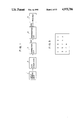
- FIG. 1 is a block diagram showing an embodiment of the resent invention.
- Image data is read by an input sensor unit 1 having a photoelectric converting device such as a CCD or the like and a drive system to scan it.
- the read image data is sequentially transferred to an A/D converter 2.
- the A/D converter 2 converts data of each pixel to digital data of eight bits.
- image data is digitized into the data having gradations of 256 levels.
- a correction circuit 3 a shading correction and the like are executed by digital arithmetic operating processes in order to correct a sensitivity variation of the sensor and an illuminance variation due to an irradiating light source.
- a corrected signal 100 is input to a binarization circuit 4 and is binarized by an error diffusion method.
- the binarized data is input as a signal 200 to a printer 5 and output as an image.
- FIG. 2 is a block diagram showing the details of the binarization circuit 4.
- the corrected data 100 (x ij ) is input to a comparator 6 and an adder 7.
- a weight coefficient ⁇ ij designated by a weighting circuit 9 is normalized and multiplexed to an error ⁇ ij (difference between correction data x ij ' which has previously been generated and output data y ij ) stored in an error buffer memory 10 and the resultant data is added to the data 100 by the adder 7.
- the added data is output as a signal 101 from the adder 7.
- Such processes can be expressed by the following equation, ##EQU1##
- FIG. 3 shows an example of weight coefficients ⁇ ij .
- * denotes the position of the pixel which is at present being processed.
- the signal 101 is input to a selector 8. When the signal 102 is at the "0" level, output data 103 is set to "0". If the signal 102 is at the "1" level, the output data 103 is set to the value of the signal 101.
- an image data in the portion of low concentration (the background in a character section or the like) is forcedly set to "0". In this portion, no dot appears. Thus, the appearance of dots in the background portion of characters or in the white portion can be prevented.
- the data y ij is the binarized data of D max or 0.
- the binarized data y ij is stored in an output buffer 13, and subsequently is output therefrom as signal 200.
- a calculator 12 calculates the difference ⁇ ij between the correction data 103 (x ij ') and the output data 104 (y ij ). The result is stored in a memory area in the error buffer memory 10 corresponding to a pixel position 14. By repeating the operations mentioned above, the binarization is executed on the basis of the error diffusion method.
- the image data 101 added with the error data is forcedly set to 0. Therefore, the output image does not preserve the concentration of the original.
- FIG. 4 is a block diagram showing the case where a part of the binarization circuit 4 in FIG. 2 has been modified.
- the corrected data 100 (x ij ) is input to a comparator 15 and an adder 16.
- the weight coefficient ⁇ ij designated by a weighting circuit 17 is normalized and multiplexed to the error ⁇ ij (difference between the correction data x ij ' which has previously been generated and the output data y ij ) stored in an error buffer memory 21 and the resultant data is added to the data 100 by the adder 16.
- the added data is output as a signal 112 from the adder 16.
- the above processes can be expressed by the following equation; ##EQU2##
- the binarized data is stored into an output buffer 20 and data 200 is output therefrom.
- a calculator 19 calculates the difference ⁇ ij between the correction data 112 (x ij ') and the output data 113 (y ij ). The result is stored into a memory area in the error buffer memory 21 corresponding to a pixel position 22. By repeating the foregoing operations, the binarization is executed on the basis of the error diffusion method.
- FIG. 5 is a block diagram showing a case where the invention is applied to a color image.
- Three color-separated red, green, and blue signals are output from a color image input unit 23 and converted into 8-bit digital signals by an A/D converter 24, one for every color.
- a correction circuit 25 a shading correction, a complementary color conversion from RGB signals to YMC signals, a masking process, and the like are executed, so that yellow (Y), magenta (M), and cyan (C) signals are output.
- the Y, M, and C signals are input to a binarization circuit 26, by which the background process of the character portion and the binarization are executed.
- the binarization circuit 26 can be realized by providing the binarization circuit 4 in FIG. 1 for three colors of Y, M, and C.
- the binarized data is output as a color image by a printer 27.
- FIG. 6 the parts and components which execute the same processes as those in FIG. 1 are designated by the same reference numerals and their descriptions are omitted
- the corrected signal 100 is input to a comparator 51 and a binarization circuit 52.
- T 1 10 in the example
- the binarization circuit 52 the binarization based on the error diffusion method or the like is executed for the input data 100.
- Binarized data 122 is input to an AND circuit 53 and the AND of the data 122 and signal 121 is calculated. The AND here denotes that "255” is output when both of the signals 121 and 122 are set to "255" (in the case of eight bits) and that "0" is output in the other cases.
- the data 123 output from the AND circuit 53 is transferred to the printer 5 and output as an image.
- the input data has been set to eight bits.
- the processes can be also similarly executed in the case where the input data is set to 5 to 6 bits as in the facsimile apparatus.
- the background (other than the character portion) of an image can be also erased.
- FIG. 7 is a diagram showing the binarization circuit 52 in FIG. 6.
- the description of the binarization circuit 52 is substantially the same as that in the case where the comparator 15 in FIG. 4 is omitted. Therefore, it is omitted here.
- concentration data 103 of an image by setting concentration data 103 of an image to "1" or "2" and outputting, a predetermined number of dots can be also allowed to appear.
- the dots appearing in the background portion of the character portion or white portion can be erased or reduced and a reproduction image of a high quality can be obtained.
- FIG. 8 is a block diagram of a facsimile apparatus to which the invention is applied.
- reference numeral 201 denotes a network control unit (NCU) for connecting a telephone line 201a, a telephone 202, and a hybrid circuit 203 on the side of a data communicating apparatus and for holding a control loop.
- Reference numeral 202 denotes the telephone and 203 indicates the hybrid circuit to separate a signal of the transmission system and a signal of the reception system.
- a transmission signal from a signal line 203b is transmitted to the telephone line 201a through a signal line 201c and NCU 201 and a signal sent from a partner side is output to a signal line 203a through the NCU 201 and signal line 201c.
- Reference numeral 206 denotes a read and binarization circuit for sequentially reading an image signal of one line in the main scanning direction from a transmission original and for producing a signal train indicative of binary values of white and black on the basis of the error diffusion method.
- the read and binarization circuit comprises: an image pickup device such as a CCD (charge coupled device) or the like; an optical system; and a binarization circuit for converting read luminance data into concentration data and for binarizing by the error diffusion method.
- the binarization circuit will be described in detail hereinlater.
- the binarized signal train of white and black is output to a signal line 206a.
- Reference numeral 205 denotes an encode circuit for receiving the binarization data which was output to the signal line 206a and binarized by the error diffusion method and for outputting to a signal line 205a the MH (Modified Huffman) encoded or MR (Modified READ) encoded data.
- MH Modified Huffman
- MR Modified READ
- Reference numeral 204 denotes a modulator to perform the modulation based on the well-known CCITT Recommendation V27 ter (differential phase modulation) or V29 (orthogonal modulation).
- the modulator 204 receives the signal from the signal line 205a and modulates and outputs the modulated data to the signal line 203b.
- Reference numeral 207 denotes a demodulator to perform the demodulation on the basis of the well-known CCITT recommendation V27 ter or V29.
- the demodulator 207 receives the signal from the signal line 203a and demodulates and outputs the demodulated data to a signal line 207a.
- Reference numeral 208 denotes a decode circuit for receiving the demodulated data from the signal line 207a and outputting the decoded (MH or MR decoded) data to a signal line 208b.
- Reference numeral 209 indicates a record circuit for receiving the signal output to the signal line 208b and sequentially recording every line.
- the signal train of one scanning line from the read and binarization circuit 206 can be alternately divided into the white portion and black portion as shown in FIG. 9.
- A, C, and E indicate the white portions and B and D represent the black portions.
- the number of pixels in each of the white and black portions is called a run length.
- the color (white or black) of A to E and the run length are encoded and the image data is compressed and, thereafter, the compressed data is sent to the modulator 204.
- each run is encoded by the Huffman code.
- the Huffman code consists of a terminating code and a make-up code.
- a compression ratio improves as the run of the same color is longer.
- FIG. 10 is a diagram showing the details of the read and binarization circuit 26 in FIG. 8. The binarizing process by the error diffusion method will now be described hereinbelow with reference to FIG. 10.
- An input sensor unit 231 comprises a photoelectric converting device such as a CCD or the like and a drive unit to scan it and reads and scans an original
- the image data read by the input sensor unit 231 is sent to an A/D converter 232.
- the A/D converter 232 converts the image data of each pixel into the digital data of six bits, that is, digitizes into the data having gradations of 64 levels.
- the shading distortion correction is executed to correct a sensitivity variation of the CCD and an illuminance variation of a light source.
- luminance data ⁇ (black) ⁇ 63 (white) respectively is used and the luminance data is input to a conversion table 234 and converted into the concentration data.
- FIG. 11 shows an example in which an ROM is used as the conversion table.
- the content in which the luminance data is used as input data and the concentration data is used as output data is written in the ROM in FIG. 11.
- FIG. 12 shows an input/output correspondence table of the conversion table.
- the luminance data from the correction circuit 233 is input to addresses A ⁇ to A5 in the ROM in FIG. 11.
- the concentration data based on the input/output correspondence table in FIG. 16 is output as output data to an error correction circuit 235 from O 0 to O 5 in FIG. 11.
- the input data values (luminance data) of 57 or more (white) are all set such that the output data values (concentration data) are set to ⁇ .
- the output data X i ,j is the concentration data ⁇ (white) ⁇ 63 (black).
- error data E i ,j calculated by an error calculation circuit 237 is added to the output data X i ,j of the conversion table. That is, assuming that the output data of the error correction circuit 235 is Z i ,j, it can be expressed by the following equation:
- the output data Z i ,j is sent to a binarization circuit 236 and compared with a threshold value TH and converted into a binary value. That is,
- the data Z i ,j is also sent to the error calculation circuit 237 and the error is calculated. Namely, when Z i ,j is larger than the threshold value TH,
- ⁇ i ,j is weighted by an error matrix shown in FIG. 13 and is output as the error value E i ,j and is returned to the error correction circuit 235.
- reference numeral 243 denotes an objective pixel
- i in 241 indicates a main scanning direction
- j in 242 represents a sub-scanning direction.
- the error values generated when the binarization was executed for the objective pixel 243 are diffused to (i+1, j), (i+2, j), (i, j+1), and (i+1, j+1).
- the binarization data P i ,j is sent to the encode circuit 205 and encoded by the MH or MR encoding system on the basis of the binarization data P i ,j.
- the encoding process in the encode circuit 205 can be efficiently executed in the highlight portion. That is, this is because by setting the concentration to 0 for the luminance data of a predetermined value or more, the occurrence of black dots in the highlight portion after completion of the binarization by the error diffusion method is prevented.
- the encode circuit 205 has line buffers of at least one line for encoding.
- Reference numerals 251, 252, 253, and 254 denote delay units which generally consist of latch circuits. Each of the delay sections 251 to 254 delays by a time corresponding to one pixel.
- Reference numerals 255, 256, and 257 indicate adders each for performing the addition or subtraction of the error data and error data to calculate the error in the error matrix in FIG. 13.
- Reference numeral 258 denotes an error line memory using, e.g., a FIFO (first-in first-out) memory.
- the error line memory 258 stores the result of the calculation of the errors of one line and delays by a time corresponding to one line.
- the error data ⁇ i ,j calculated by the error calculation circuit 237 in FIG. 10 is distributed to four peripheral pixels in accordance with the error matrix in FIG. 13.
- An output of the adder 255 is stored into the error line memory 258.
- After the error data stored is delayed by a time of one line, it is further delayed by a time of one pixel by the delay unit 252 and added to ⁇ i ,j by the adder 256.
- the error data generated by the other pixels are added through the delay units and adder (253, 257, and 254) and the error value E i ,j is output.
- the error value E i ,j generated in the pixel which has already been processed is added in accordance with the error matrix.
- the luminance-concentration conversion table is set before the binarizing process based on the error diffusion method and the luminance data of a predetermined value or more is set to the concentration data 0, so that the increase amount of the errors in the error diffusion method can be set to 0.
- the particle like noises in the highlight portion can be certainly eliminated at a high speed.
- the encoding process in the facsimile apparatus can be also efficiently executed.
- an image of a high picture quality having excellent resolution and gradations can be transmitted at a high speed without largely deteriorating the encoding efficiency.
- FIG. 15 is a hardware arrangement diagram showing another embodiment of the read and binarization circuit in FIG. 8.
- Reference numeral 260 denotes an input sensor unit to read an original; 261 indicates an A/D converter; 262 a correction circuit to perform the shading correction and the like; 263 a conversion table to convert the luminance data into the concentration data; 264 a comparator; 265 an error correction circuit to add an error value to the concentration of an original pixel; 266 a binarization circuit to convert the multi value data into the binary data; 267 an error calculation circuit to calculate errors; 268 an AND circuit; and 205 the same as the encode circuit 205 in FIG. 8.
- the input sensor unit 260 comprises a photoelectric converting device such as a CCD or the like and a drive unit to scan it and reads and scans an original.
- the image data read by the input sensor unit 260 is sent to the A/D converter 261.
- the A/D converter 261 converts the image data of each pixel into the digital data of, e.g., six bits, thereby digitizing into the data having the gradations of 64 levels.
- the shading distortion correction is executed to correct a sensitivity variation of the CCD and an illuminance variation of a light source.
- the data here is the luminance data 0 (black) to 63 (white), respectively.
- the luminance data is input to the conversion table 263 and converted into the concentration data.
- the ROM of the conversion table has the same constitution as that shown in FIG. 11 but the content of the conversion table differs That is, the content such that the luminance data is set to the input data and the concentration data is set to the output data is written in the ROM.
- FIG. 16 shows an input/output correspondence table of the conversion table. Namely, the luminance data from the correction circuit 262 is input to addresses A0 to A5 in the ROM. The concentration data based on the input/output correspondence table in FIG. 16 is output as the output data to the error correction circuit 265 from O 0 to O 5 .
- the error data E i ,j calculated by the error calculation circuit 267 is added to the output data X i ,j of the conversion table 263.
- Suffixes (i,j) denote the ith pixel data of the jth line. Assuming that the output data of the error correction circuit is set to Z i ,j, it can be expressed by the following equation;
- the output data Z i ,j is sent to the binarization circuit 266 and compared with the threshold value TH and converted into a binary value. That is,
- the Z i ,j is also sent to the error calculation circuit 267 and the errors are calculated.
- ⁇ i ,j is weighted by the error matrix shown in FIG. 13 as mentioned above and is returned as the error value E i ,j to the error correction circuit 265.
- the output Z i ,j from the error correction circuit 265 is compared with the threshold value TH by the binarization circuit 266 and the binary signal of 1 or 0 is sent to the AND circuit 268. Since the error calculation circuit 267 has the same constitution as that in FIG. 14, its detailed description is omitted here.
- X i ,j is compared with a preset value by the comparator 264.
- the encode circuit 205 performs the encoding process by the MH or MR system on the basis of the output from the AND circuit 268.
- the encoding process by the encode circuit 205 can be efficiently performed in the highlight portion. That is, by binarizing such that the concentration data of a predetermined concentration or less is converted into 0 irrespective of the binary output of the error diffusion method, even if the concentration of the pixel is actually low, it is possible to prevent that the concentration exceeds the threshold value due to the error data.
- the generation of the particle-like noises can be prevented in the highlight portion.
- the encode circuit 205 has line buffers which can store the binary data of at least one line from the AND circuit 268 for encoding.
- the pixel concentration to be processed by the error diffusion method is a predetermined value or less
- the particle-like noises in the high contrast portion can be eliminated and there is an effect such that the image quality can be improved.
- the particle-like noises are eliminated, the encoding efficiency can be also improved.
- Reference numeral 270 denotes an input sensor unit to read an original; 271 indicates an A/D converter; 272 a correction circuit to perform the shading distortion correction and the like; 273 a conversion table to convert the luminance data into the concentration data; 274 a comparator; 275 an error correction circuit to add an error value to the concentration of the original pixel; 276 a binarization circuit to convert the multi value data into the binary data on the basis of a threshold value; 205 the encode circuit; 277 a subtraction circuit to calculate error data; 278 a circuit to output 0 as an error; 279 a switch to select either one of outputs of the circuits 277 and 278; 280 a control circuit to control a memory 282 and the like; 281 a weighting circuit; 282 the memory; and 283 an adding circuit.
- the input sensor section 270 comprises a photoelectric converting device such as a CCD or the like and a drive unit to drive it and reads and scans an original.
- Image data read by the input sensor unit 270 is sent to the A/D converter 271.
- the A/D converter 271 converts the image data of each pixel into the digital data of, e.g., six bits, thereby digitizing into the data having the gradations of 64 levels.
- shading distortion correction is executed to correct a sensitivity variation of the CCD and an illuminance variation of a light source.
- the data in this case is the luminance data 0 (black) to 63 (white) respectively; and the luminance data is input to the conversion table 104 to convert the luminance data into the concentration data.
- the values in the conversion table are the same as those shown in FIG. 16.
- the ROM in FIG. 11 is used in the converting process. That is, the luminance data is input to addresses A0 to A5 in the ROM in FIG. 11 and the output data based on the conversion table in FIG. 16 is output from the outputs O 0 to O 5 of the ROM.
- the output data X i ,j is the concentration data 0 (white) to 63 (black) respectively.
- the output data E i ,j of the adding circuit 283 is added to the output data X i ,j of the conversion table 273 and the data Z i ,j is output.
- Suffixes (i,j) represent the ith pixel data of the jth line. That is, the output data Z i ,j of the error correction circuit can be expressed by the following equation;
- Z i ,j is sent to the binarization circuit 276 and compared with the threshold value TH and converted into the binary data P i ,j. That is,
- the output data P i ,j of the binarization circuit is subtracted from the output data Z i ,j of the error correction circuit by the subtraction circuit 277. That is, assuming that the output data of the subtraction circuit 277 is set to E i ,j,
- E i ,j is input to the switch 279.
- the output of the circuit 278 is also input to the switch 279.
- the circuit 278 always outputs the 0 data.
- the switch 279 selects one of the two input data by a control signal S i ,j and outputs.
- the control signal S i ,j is output from the comparator 274.
- S i ,j is set to the high (H) level.
- S i ,j is set to the low (L) level.
- S i ,j is at the H level, the switch 279 selects the output signal of the circuit 278 as output data.
- the switch 279 selects the output data of the circuit 277. This is because if the input data has a brightness of the threshold value BTH or less, it is determined that the human eyes feel the image as white. Therefore, in such a high contrast portion, the errors are forcedly set to 0, thereby preventing the generation of a black dot.
- the output data E i ,j (errors) of the switch 279 is weighted by the weighting circuit 281 and the errors are spatially diffused.
- the weighting circuit 281 adds weights in accordance with the error matrix shown in FIG. 13. According to the error matrix, since the errors are diffused to the jth line and (j+1)th line, the data B i ,j to be diffused to the (j+1)th line is stored into the memory 282.
- the output signal P i ,j of the binarization circuit 276 is sent to the encode circuit 205 and is encoded by the MH or MR encoding system in accordance with the value of the output signal P i ,j.
- the encoding process in the encode circuit 205 can be efficiently performed in the highlight portion. That is, since the diffusion errors in the error diffusion method are set to 0 for the concentration data of a predetermined concentration or less, even if the concentration of the pixel is actually low, it is possible to prevent that the concentration exceeds the threshold value due to the error data. The generation of the particle-like noises in the highlight portion can be prevented.
- the encode circuit 205 has line buffers which can store the binary data from the AND circuit 268 or binarization circuit 276 in FIG. 15 of at least one line in order to encode.
- the pixel concentration to be processed by the error diffusion method is a predetermined value or less
- the particle-like noises in the high contrast portion can be eliminated and there is an advantage such that the image quality is improved.
- the encoding efficiency can be also improved.
- the facsimile apparatus of the embodiment since the image is half-tone processed by using the error diffusion method, the image of a high picture quality having excellent resolution and gradations can be transmitted. Further, the encoding process in the highlight portion of an image can be efficiently performed and a good image can be transmitted at a high speed.
- the embodiment has been described with respect to the case where the image data is binarized by the error diffusion method (least mean error method) as a digitizing method, the invention can be also similarly applied to the case of converting the image data to multi-values by the error diffusion method.
- error diffusion method least mean error method
Abstract
Description
Z.sub.i,j =X.sub.i,j +E.sub.i,j
α.sub.i,j =(63-Z.sub.i,j)/10
α.sub.i,j =(Z.sub.i,j /10)
Z.sub.i,j =X.sub.i,j +E.sub.i,j
α.sub.i,j =(63-Z.sub.i,j)/10
α.sub.i,j =(Z.sub.i,j /10)
Z.sub.i,j =X.sub.i,j +E.sub.i,j
E.sub.i,j =Z.sub.i,j -P.sub.i,j
Claims (32)
Applications Claiming Priority (6)
| Application Number | Priority Date | Filing Date | Title |
|---|---|---|---|
| JP62-334975 | 1987-12-28 | ||
| JP62334975A JP2675792B2 (en) | 1987-12-28 | 1987-12-28 | Image processing device |
| JP63043115A JP2667860B2 (en) | 1988-02-25 | 1988-02-25 | Image processing method and apparatus |
| JP63-043115 | 1988-02-25 | ||
| JP63043114A JP2622141B2 (en) | 1988-02-25 | 1988-02-25 | Image processing method |
| JP63-043114 | 1988-02-25 |
Publications (1)
| Publication Number | Publication Date |
|---|---|
| US4975786A true US4975786A (en) | 1990-12-04 |
Family
ID=27291440
Family Applications (1)
| Application Number | Title | Priority Date | Filing Date |
|---|---|---|---|
| US07/289,017 Expired - Lifetime US4975786A (en) | 1987-12-28 | 1988-12-23 | Image processing method and apparatus with error diffusion capability |
Country Status (1)
| Country | Link |
|---|---|
| US (1) | US4975786A (en) |
Cited By (62)
| Publication number | Priority date | Publication date | Assignee | Title |
|---|---|---|---|---|
| US5077812A (en) * | 1989-08-30 | 1991-12-31 | Kabushiki Kaisha Toshiba | Image processing apparatus |
| US5109282A (en) * | 1990-06-20 | 1992-04-28 | Eye Research Institute Of Retina Foundation | Halftone imaging method and apparatus utilizing pyramidol error convergence |
| US5121446A (en) * | 1989-02-10 | 1992-06-09 | Canon Kabushiki Kaisha | Image processing apparatus capable of obtaining multi-level data |
| US5121447A (en) * | 1989-04-27 | 1992-06-09 | Canon Kabushiki Kaisha | Apparatus for performing gradation processing on image data |
| US5130823A (en) * | 1991-06-27 | 1992-07-14 | Cactus | Error diffusion system |
| US5134668A (en) * | 1990-02-08 | 1992-07-28 | International Business Machines Corporation | Masked combinations of video slices for computer display |
| US5162925A (en) * | 1988-11-17 | 1992-11-10 | Canon Kabushiki Kaisha | Color image processor capable of performing masking using a reduced number of bits |
| US5164717A (en) * | 1989-09-28 | 1992-11-17 | Sun Microsystems, Inc. | Method and apparatus for the dithering of antialiased vectors |
| US5201013A (en) * | 1989-04-24 | 1993-04-06 | Ezel, Inc. | Dither processing method |
| US5208871A (en) * | 1990-10-19 | 1993-05-04 | Xerox Corporation | Pixel quantization with adaptive error diffusion |
| US5235436A (en) * | 1990-03-02 | 1993-08-10 | Canon Kabushiki Kaisha | Image processing apparatus |
| US5245444A (en) * | 1990-03-26 | 1993-09-14 | Canon Kabushiki Kaisha | Image reproduction using error diffusion or dither matrix |
| US5253936A (en) * | 1989-11-16 | 1993-10-19 | Canon Kabushiki Kaisha | Data communication apparatus and data communication method |
| US5268774A (en) * | 1991-11-27 | 1993-12-07 | Xerox Corporation | Halftoning with enhanced dynamic range and edge enhanced error diffusion |
| US5307426A (en) * | 1990-09-11 | 1994-04-26 | Kabushiki Kaisha Toshiba | Image processing apparatus with improved dithering scheme |
| US5323247A (en) * | 1990-12-04 | 1994-06-21 | Research Corporation Technologies | Method and apparatus for halftoning and inverse halftoning and the transmission of such images |
| US5329380A (en) * | 1991-01-28 | 1994-07-12 | Canon Kabushiki Kaisha | Image processing machine |
| US5333260A (en) * | 1992-10-15 | 1994-07-26 | Digital Equipment Corporation | Imaging system with multilevel dithering using bit shifter |
| US5333262A (en) * | 1992-10-15 | 1994-07-26 | Ulichney Robert A | Imaging system with multilevel dithering using two memories |
| US5341228A (en) * | 1990-12-04 | 1994-08-23 | Research Corporation Technologies | Method and apparatus for halftone rendering of a gray scale image using a blue noise mask |
| US5359433A (en) * | 1990-02-01 | 1994-10-25 | Canon Kabushiki Kaisha | Image processing apparatus with reduced image deterioration in highlight portions |
| US5361147A (en) * | 1990-02-06 | 1994-11-01 | Canon Kabushiki Kaisha | Method and apparatus for encoding and decoding color images |
| US5363210A (en) * | 1991-09-30 | 1994-11-08 | Ricoh Company, Ltd. | Apparatus outputting quantized image data, selecting from filters with different error spreading effects |
| US5379130A (en) * | 1992-12-02 | 1995-01-03 | Industrial Technology Research Institute | Text/image separation method |
| US5388167A (en) * | 1991-03-12 | 1995-02-07 | Hitachi, Ltd. | Document image processing system and document image processing method |
| US5387983A (en) * | 1991-09-27 | 1995-02-07 | Minolta Camera Kabushiki Kaisha | Facsimile apparatus comprising converting means for converting binary image data into multi-value image data and image processing apparatus judging pseudo half-tone image |
| US5406392A (en) * | 1988-11-15 | 1995-04-11 | Canon Kabushiki Kaisha | Image recording apparatus using multiple recording of the same image information to obtain high resolution and tonality |
| US5422735A (en) * | 1993-09-16 | 1995-06-06 | Fujitsu Limited | Image processing method and image processing apparatus |
| US5436736A (en) * | 1991-03-15 | 1995-07-25 | Canon Kabushiki Kaisha | Image processing apparatus |
| US5448656A (en) * | 1989-10-23 | 1995-09-05 | Sharp Kabushiki Kaisha | Binary image processing apparatus |
| US5463472A (en) * | 1991-02-22 | 1995-10-31 | At&T Corp. | Model-based halftoning |
| US5463295A (en) * | 1991-06-07 | 1995-10-31 | Canon Kabushiki Kaisha | Facsimile apparatus with control of resolution to be compatible with receiving side |
| US5475497A (en) * | 1991-02-22 | 1995-12-12 | At&T Ipm Corp. | Two-dimensional display model-based halftoning |
| US5489991A (en) * | 1992-10-09 | 1996-02-06 | International Business Machines Corporation | Method for generating digital halftone images |
| US5495345A (en) * | 1992-10-15 | 1996-02-27 | Digital Equipment Corporation | Imaging system with two level dithering using comparator |
| US5502495A (en) * | 1991-01-25 | 1996-03-26 | Canon Kabushiki Kaisha | Image processing capable of providing higher resolution in low-density regions |
| US5508822A (en) * | 1992-10-15 | 1996-04-16 | Digital Equipment Corporation | Imaging system with multilevel dithering using single memory |
| US5539667A (en) * | 1992-09-15 | 1996-07-23 | Gcc Technologies | Method and apparatus for improved digital film recorder |
| US5543936A (en) * | 1992-10-15 | 1996-08-06 | Digital Equipment Corporation | Image adjustment system for translating raw input levels to adjusted input levels |
| US5577136A (en) * | 1989-09-27 | 1996-11-19 | Canon Kabushiki Kaisha | Image processing apparatus |
| US5590190A (en) * | 1989-10-31 | 1996-12-31 | Canon Kabushiki Kaisha | Data communication apparatus including volatile and non-volatile storage |
| US5638188A (en) * | 1993-07-19 | 1997-06-10 | Canon Kabushiki Kaisha | Image processing method and apparatus with storing and selecting of dot patterns |
| US5642204A (en) * | 1992-12-02 | 1997-06-24 | Industrial Technology Research Institute | Error diffusion method |
| US5661575A (en) * | 1990-10-09 | 1997-08-26 | Matsushita Electric Industrial Co., Ltd. | Gradation correction method and device |
| US5668646A (en) * | 1990-02-06 | 1997-09-16 | Canon Kabushiki Kaisha | Apparatus and method for decoding differently encoded multi-level and binary image data, the later corresponding to a color in the original image |
| US5699167A (en) * | 1993-09-30 | 1997-12-16 | Canon Kabushiki Kaisha | Image forming apparatus which outputs a color image by separating color image information into at least two color components |
| US5748772A (en) * | 1993-07-19 | 1998-05-05 | Canon Kabushiki Kaisha | Image processing method and apparatus including an error calculation for calculating a difference between the values of error correction data and stored representative values |
| US5812279A (en) * | 1990-11-10 | 1998-09-22 | Minolta Co., Ltd. | Facsimile machine capable of efficient transmission processing |
| US5825940A (en) * | 1995-01-23 | 1998-10-20 | Canon Kabushiki Kaisha | Image processing method and apparatus for binary-coding multivalue image data |
| US5926570A (en) * | 1997-04-18 | 1999-07-20 | Contex A/S | Optical scanner using dithering with adaptive threshold |
| US6091891A (en) * | 1997-05-09 | 2000-07-18 | Lexmark International, Inc. | Method and apparatus for calibrating delay lines to create gray levels in continuous tone printing |
| US6115504A (en) * | 1993-02-16 | 2000-09-05 | Minolta Co., Ltd. | Image processing apparatus employing error diffusion type binarizing system |
| US6134355A (en) * | 1989-02-10 | 2000-10-17 | Canon Kabushiki Kaisha | Binarization using a local average, and using error diffusion |
| US6249354B1 (en) * | 1997-02-14 | 2001-06-19 | Canon Kabushiki Kaisha | Image processing apparatus and method |
| US6262809B1 (en) * | 1991-12-27 | 2001-07-17 | Minolta Co., Ltd. | Image processing apparatus shifting image data between adjacent picture elements |
| US6278527B1 (en) | 1994-12-27 | 2001-08-21 | Canon Kabushiki Kaisha | Output apparatus and output method |
| US20010024522A1 (en) * | 2000-03-14 | 2001-09-27 | Takehisa Nakao | Image processing apparatus |
| US6501566B1 (en) * | 1977-04-03 | 2002-12-31 | Minolta Co., Ltd. | Image processing apparatus carrying out multi-value error diffusion process |
| US6545696B1 (en) * | 1999-04-27 | 2003-04-08 | Mitsubishi Denki Kabushiki Kaisha | Optical printing apparatus |
| US6693727B1 (en) | 1998-11-17 | 2004-02-17 | Kabushiki Kaisha Toshiba | Image processing apparatus for performing high-speed error diffusion |
| US6914700B2 (en) | 2003-04-17 | 2005-07-05 | Lexmark International, Inc. | Method for reducing migrating residual error in error diffusion halftoning |
| US20090141353A1 (en) * | 2005-03-14 | 2009-06-04 | Hiroshi Funada | Image display body and image formation method |
Citations (19)
| Publication number | Priority date | Publication date | Assignee | Title |
|---|---|---|---|---|
| DE2300515A1 (en) * | 1972-01-05 | 1973-07-19 | Crosfield Electronics Ltd | SCANNER FOR REPRODUCTION PURPOSES |
| US4258393A (en) * | 1978-11-06 | 1981-03-24 | Ricoh Company, Ltd. | Picture processing method |
| US4274111A (en) * | 1979-04-18 | 1981-06-16 | Ricoh Co., Ltd. | Color facsimile signal transmission system |
| US4298895A (en) * | 1978-08-31 | 1981-11-03 | Fuji Xerox Co., Ltd. | Visual image noise eliminating system |
| US4305093A (en) * | 1978-06-22 | 1981-12-08 | International Electronic Photo Process Laboratory Co., Ltd. | Method of producing multiple images in a scanning apparatus |
| DE3241365A1 (en) * | 1981-11-09 | 1983-05-26 | Ricoh Co., Ltd., Tokyo | METHOD AND DEVICE FOR COMPENSATING AN IMAGE IN AN IMAGE DISPLAY SYSTEM |
| US4386366A (en) * | 1980-03-26 | 1983-05-31 | Fuji Photo Film Co. Ltd. | Adaptive type quantizer |
| US4389677A (en) * | 1980-12-08 | 1983-06-21 | Ncr Canada Ltd - Ncr Canada Ltee | Method and apparatus for removing erroneous elements from digital images |
| DE3311911A1 (en) * | 1983-03-31 | 1984-10-04 | Siemens AG, 1000 Berlin und 8000 München | METHOD AND CIRCUIT ARRANGEMENT FOR IMAGE ERROR CORRECTION |
| US4495522A (en) * | 1981-07-07 | 1985-01-22 | Konishiroku Photo Industry Co., Ltd. | Recording apparatus and method of picture image |
| US4534059A (en) * | 1981-10-13 | 1985-08-06 | Dainippon Screen Seizo Kabushiki Kaisha | Method for correcting gradation of output data, for use in a picture digital processing system |
| US4562486A (en) * | 1982-05-21 | 1985-12-31 | Ricoh Company, Ltd. | Conversion of multilevel digital data to binary data |
| US4651287A (en) * | 1984-06-14 | 1987-03-17 | Tsao Sherman H | Digital image processing algorithm for output devices with discrete halftone gray scale capability |
| US4654721A (en) * | 1985-04-12 | 1987-03-31 | International Business Machines Corporation | System for reproducing multi-level digital images on a bi-level printer of fixed dot size |
| US4668995A (en) * | 1985-04-12 | 1987-05-26 | International Business Machines Corporation | System for reproducing mixed images |
| US4675704A (en) * | 1983-11-14 | 1987-06-23 | Kabushiki Kaisha Toshiba | Method and apparatus for reproducing color image |
| US4682215A (en) * | 1984-05-28 | 1987-07-21 | Ricoh Company, Ltd. | Coding system for image processing apparatus |
| US4686579A (en) * | 1984-10-11 | 1987-08-11 | Canon Kabushiki Kaisha | Image processing apparatus |
| US4821334A (en) * | 1984-12-28 | 1989-04-11 | Canon Kabushiki Kaisha | Image processing apparatus |
-
1988
- 1988-12-23 US US07/289,017 patent/US4975786A/en not_active Expired - Lifetime
Patent Citations (22)
| Publication number | Priority date | Publication date | Assignee | Title |
|---|---|---|---|---|
| GB1374521A (en) * | 1972-01-05 | 1974-11-20 | Crosfield Electronics Ltd | Image reproducing methods and apparatus |
| DE2300515A1 (en) * | 1972-01-05 | 1973-07-19 | Crosfield Electronics Ltd | SCANNER FOR REPRODUCTION PURPOSES |
| US4305093A (en) * | 1978-06-22 | 1981-12-08 | International Electronic Photo Process Laboratory Co., Ltd. | Method of producing multiple images in a scanning apparatus |
| US4298895A (en) * | 1978-08-31 | 1981-11-03 | Fuji Xerox Co., Ltd. | Visual image noise eliminating system |
| US4258393A (en) * | 1978-11-06 | 1981-03-24 | Ricoh Company, Ltd. | Picture processing method |
| US4274111A (en) * | 1979-04-18 | 1981-06-16 | Ricoh Co., Ltd. | Color facsimile signal transmission system |
| US4386366A (en) * | 1980-03-26 | 1983-05-31 | Fuji Photo Film Co. Ltd. | Adaptive type quantizer |
| US4389677A (en) * | 1980-12-08 | 1983-06-21 | Ncr Canada Ltd - Ncr Canada Ltee | Method and apparatus for removing erroneous elements from digital images |
| US4495522A (en) * | 1981-07-07 | 1985-01-22 | Konishiroku Photo Industry Co., Ltd. | Recording apparatus and method of picture image |
| US4534059A (en) * | 1981-10-13 | 1985-08-06 | Dainippon Screen Seizo Kabushiki Kaisha | Method for correcting gradation of output data, for use in a picture digital processing system |
| DE3241365A1 (en) * | 1981-11-09 | 1983-05-26 | Ricoh Co., Ltd., Tokyo | METHOD AND DEVICE FOR COMPENSATING AN IMAGE IN AN IMAGE DISPLAY SYSTEM |
| US4517607A (en) * | 1981-11-09 | 1985-05-14 | Ricoh Company, Ltd. | Method of and apparatus for compensating image in image reproduction system |
| US4562486A (en) * | 1982-05-21 | 1985-12-31 | Ricoh Company, Ltd. | Conversion of multilevel digital data to binary data |
| DE3311911A1 (en) * | 1983-03-31 | 1984-10-04 | Siemens AG, 1000 Berlin und 8000 München | METHOD AND CIRCUIT ARRANGEMENT FOR IMAGE ERROR CORRECTION |
| US4647972A (en) * | 1983-03-31 | 1987-03-03 | Siemens Aktiengesellschaft | Method and circuit arrangement for correction of image distortion |
| US4675704A (en) * | 1983-11-14 | 1987-06-23 | Kabushiki Kaisha Toshiba | Method and apparatus for reproducing color image |
| US4682215A (en) * | 1984-05-28 | 1987-07-21 | Ricoh Company, Ltd. | Coding system for image processing apparatus |
| US4651287A (en) * | 1984-06-14 | 1987-03-17 | Tsao Sherman H | Digital image processing algorithm for output devices with discrete halftone gray scale capability |
| US4686579A (en) * | 1984-10-11 | 1987-08-11 | Canon Kabushiki Kaisha | Image processing apparatus |
| US4821334A (en) * | 1984-12-28 | 1989-04-11 | Canon Kabushiki Kaisha | Image processing apparatus |
| US4654721A (en) * | 1985-04-12 | 1987-03-31 | International Business Machines Corporation | System for reproducing multi-level digital images on a bi-level printer of fixed dot size |
| US4668995A (en) * | 1985-04-12 | 1987-05-26 | International Business Machines Corporation | System for reproducing mixed images |
Non-Patent Citations (10)
| Title |
|---|
| "Damped Error Diffusion in Binary Display", in IBM Technical Disclosure Bulletin, vol. 28, No. 3, Aug. 1985, pp. 1290-1291. |
| "On the Error Diffusion Techniques for Electronic Halftoning", in Proc. of the SIC, vol. 24, No. 3, 1983, pp. 253-258. |
| "Snow Removal-A Noise-Stripping Process for Picture Signals", in IRE Transactions on Information Theory, Feb. 1962, pp. 129-144. |
| "Survey of Electronic Techniques for Pictorial Image Reproduction", in IEEE Transactions on Communications, vol. COM-29, Dec. 1981, pp. 1898-1925. |
| Damped Error Diffusion in Binary Display , in IBM Technical Disclosure Bulletin, vol. 28, No. 3, Aug. 1985, pp. 1290 1291. * |
| On the Error Diffusion Techniques for Electronic Halftoning , in Proc. of the SIC, vol. 24, No. 3, 1983, pp. 253 258. * |
| R. W. Floyd and L. Steinberg, "An Adaptive Algorithm For Spatial Grey Scale", SID '75 DIGEST, pp. 36-37. |
| R. W. Floyd and L. Steinberg, An Adaptive Algorithm For Spatial Grey Scale , SID 75 DIGEST, pp. 36 37. * |
| Snow Removal A Noise Stripping Process for Picture Signals , in IRE Transactions on Information Theory, Feb. 1962, pp. 129 144. * |
| Survey of Electronic Techniques for Pictorial Image Reproduction , in IEEE Transactions on Communications, vol. COM 29, Dec. 1981, pp. 1898 1925. * |
Cited By (76)
| Publication number | Priority date | Publication date | Assignee | Title |
|---|---|---|---|---|
| US6501566B1 (en) * | 1977-04-03 | 2002-12-31 | Minolta Co., Ltd. | Image processing apparatus carrying out multi-value error diffusion process |
| US5406392A (en) * | 1988-11-15 | 1995-04-11 | Canon Kabushiki Kaisha | Image recording apparatus using multiple recording of the same image information to obtain high resolution and tonality |
| US5162925A (en) * | 1988-11-17 | 1992-11-10 | Canon Kabushiki Kaisha | Color image processor capable of performing masking using a reduced number of bits |
| US5121446A (en) * | 1989-02-10 | 1992-06-09 | Canon Kabushiki Kaisha | Image processing apparatus capable of obtaining multi-level data |
| US6134355A (en) * | 1989-02-10 | 2000-10-17 | Canon Kabushiki Kaisha | Binarization using a local average, and using error diffusion |
| US5201013A (en) * | 1989-04-24 | 1993-04-06 | Ezel, Inc. | Dither processing method |
| US5315669A (en) * | 1989-04-24 | 1994-05-24 | Ezel Inc. | Dither processing method |
| US5438634A (en) * | 1989-04-24 | 1995-08-01 | Ezel Inc. | Dither processing method |
| US5121447A (en) * | 1989-04-27 | 1992-06-09 | Canon Kabushiki Kaisha | Apparatus for performing gradation processing on image data |
| US5077812A (en) * | 1989-08-30 | 1991-12-31 | Kabushiki Kaisha Toshiba | Image processing apparatus |
| US5577136A (en) * | 1989-09-27 | 1996-11-19 | Canon Kabushiki Kaisha | Image processing apparatus |
| US5164717A (en) * | 1989-09-28 | 1992-11-17 | Sun Microsystems, Inc. | Method and apparatus for the dithering of antialiased vectors |
| US5448656A (en) * | 1989-10-23 | 1995-09-05 | Sharp Kabushiki Kaisha | Binary image processing apparatus |
| US5668864A (en) * | 1989-10-31 | 1997-09-16 | Canon Kabushiki Kaisha | Data communication method and apparatus including volatile and non-volatile storage |
| US5590190A (en) * | 1989-10-31 | 1996-12-31 | Canon Kabushiki Kaisha | Data communication apparatus including volatile and non-volatile storage |
| US5253936A (en) * | 1989-11-16 | 1993-10-19 | Canon Kabushiki Kaisha | Data communication apparatus and data communication method |
| US5359433A (en) * | 1990-02-01 | 1994-10-25 | Canon Kabushiki Kaisha | Image processing apparatus with reduced image deterioration in highlight portions |
| US5909505A (en) * | 1990-02-06 | 1999-06-01 | Canon Kabushiki Kaisha | Color image encoding method and apparatus |
| US5668646A (en) * | 1990-02-06 | 1997-09-16 | Canon Kabushiki Kaisha | Apparatus and method for decoding differently encoded multi-level and binary image data, the later corresponding to a color in the original image |
| US5361147A (en) * | 1990-02-06 | 1994-11-01 | Canon Kabushiki Kaisha | Method and apparatus for encoding and decoding color images |
| US5134668A (en) * | 1990-02-08 | 1992-07-28 | International Business Machines Corporation | Masked combinations of video slices for computer display |
| US5235436A (en) * | 1990-03-02 | 1993-08-10 | Canon Kabushiki Kaisha | Image processing apparatus |
| US5245444A (en) * | 1990-03-26 | 1993-09-14 | Canon Kabushiki Kaisha | Image reproduction using error diffusion or dither matrix |
| US5109282A (en) * | 1990-06-20 | 1992-04-28 | Eye Research Institute Of Retina Foundation | Halftone imaging method and apparatus utilizing pyramidol error convergence |
| US5307426A (en) * | 1990-09-11 | 1994-04-26 | Kabushiki Kaisha Toshiba | Image processing apparatus with improved dithering scheme |
| US5661575A (en) * | 1990-10-09 | 1997-08-26 | Matsushita Electric Industrial Co., Ltd. | Gradation correction method and device |
| US6101271A (en) * | 1990-10-09 | 2000-08-08 | Matsushita Electrial Industrial Co., Ltd | Gradation correction method and device |
| US5208871A (en) * | 1990-10-19 | 1993-05-04 | Xerox Corporation | Pixel quantization with adaptive error diffusion |
| US5812279A (en) * | 1990-11-10 | 1998-09-22 | Minolta Co., Ltd. | Facsimile machine capable of efficient transmission processing |
| US5477305A (en) * | 1990-12-04 | 1995-12-19 | Research Corporation Technologies | Method and apparatus for halftone rendering of a gray scale image using a blue noise mask |
| US5323247A (en) * | 1990-12-04 | 1994-06-21 | Research Corporation Technologies | Method and apparatus for halftoning and inverse halftoning and the transmission of such images |
| US5543941A (en) * | 1990-12-04 | 1996-08-06 | Research Corporation Technologies, Inc. | Method and apparatus for halftone rendering of a gray image using a blue noise mask |
| US5708518A (en) * | 1990-12-04 | 1998-01-13 | Research Corporation Technologies, Inc. | Method and apparatus for halftone rendering of a gray scale image using a blue noise mask |
| US5726772A (en) * | 1990-12-04 | 1998-03-10 | Research Corporation Technologies | Method and apparatus for halftone rendering of a gray scale image using a blue noise mask |
| US5341228A (en) * | 1990-12-04 | 1994-08-23 | Research Corporation Technologies | Method and apparatus for halftone rendering of a gray scale image using a blue noise mask |
| US5502495A (en) * | 1991-01-25 | 1996-03-26 | Canon Kabushiki Kaisha | Image processing capable of providing higher resolution in low-density regions |
| US5329380A (en) * | 1991-01-28 | 1994-07-12 | Canon Kabushiki Kaisha | Image processing machine |
| US5475497A (en) * | 1991-02-22 | 1995-12-12 | At&T Ipm Corp. | Two-dimensional display model-based halftoning |
| US5463472A (en) * | 1991-02-22 | 1995-10-31 | At&T Corp. | Model-based halftoning |
| US5388167A (en) * | 1991-03-12 | 1995-02-07 | Hitachi, Ltd. | Document image processing system and document image processing method |
| US5436736A (en) * | 1991-03-15 | 1995-07-25 | Canon Kabushiki Kaisha | Image processing apparatus |
| US5463295A (en) * | 1991-06-07 | 1995-10-31 | Canon Kabushiki Kaisha | Facsimile apparatus with control of resolution to be compatible with receiving side |
| US5130823A (en) * | 1991-06-27 | 1992-07-14 | Cactus | Error diffusion system |
| US5387983A (en) * | 1991-09-27 | 1995-02-07 | Minolta Camera Kabushiki Kaisha | Facsimile apparatus comprising converting means for converting binary image data into multi-value image data and image processing apparatus judging pseudo half-tone image |
| US5363210A (en) * | 1991-09-30 | 1994-11-08 | Ricoh Company, Ltd. | Apparatus outputting quantized image data, selecting from filters with different error spreading effects |
| US5268774A (en) * | 1991-11-27 | 1993-12-07 | Xerox Corporation | Halftoning with enhanced dynamic range and edge enhanced error diffusion |
| US6262809B1 (en) * | 1991-12-27 | 2001-07-17 | Minolta Co., Ltd. | Image processing apparatus shifting image data between adjacent picture elements |
| US5539667A (en) * | 1992-09-15 | 1996-07-23 | Gcc Technologies | Method and apparatus for improved digital film recorder |
| US5489991A (en) * | 1992-10-09 | 1996-02-06 | International Business Machines Corporation | Method for generating digital halftone images |
| US5495345A (en) * | 1992-10-15 | 1996-02-27 | Digital Equipment Corporation | Imaging system with two level dithering using comparator |
| US5543936A (en) * | 1992-10-15 | 1996-08-06 | Digital Equipment Corporation | Image adjustment system for translating raw input levels to adjusted input levels |
| US5333260A (en) * | 1992-10-15 | 1994-07-26 | Digital Equipment Corporation | Imaging system with multilevel dithering using bit shifter |
| US5333262A (en) * | 1992-10-15 | 1994-07-26 | Ulichney Robert A | Imaging system with multilevel dithering using two memories |
| US5508822A (en) * | 1992-10-15 | 1996-04-16 | Digital Equipment Corporation | Imaging system with multilevel dithering using single memory |
| US5379130A (en) * | 1992-12-02 | 1995-01-03 | Industrial Technology Research Institute | Text/image separation method |
| US5642204A (en) * | 1992-12-02 | 1997-06-24 | Industrial Technology Research Institute | Error diffusion method |
| US6115504A (en) * | 1993-02-16 | 2000-09-05 | Minolta Co., Ltd. | Image processing apparatus employing error diffusion type binarizing system |
| US5638188A (en) * | 1993-07-19 | 1997-06-10 | Canon Kabushiki Kaisha | Image processing method and apparatus with storing and selecting of dot patterns |
| US5748772A (en) * | 1993-07-19 | 1998-05-05 | Canon Kabushiki Kaisha | Image processing method and apparatus including an error calculation for calculating a difference between the values of error correction data and stored representative values |
| US5422735A (en) * | 1993-09-16 | 1995-06-06 | Fujitsu Limited | Image processing method and image processing apparatus |
| US6134023A (en) * | 1993-09-30 | 2000-10-17 | Canon Kabushiki Kaisha | Image forming apparatus which outputs a color image by separating color image information into at least two color components |
| US5699167A (en) * | 1993-09-30 | 1997-12-16 | Canon Kabushiki Kaisha | Image forming apparatus which outputs a color image by separating color image information into at least two color components |
| US6665087B2 (en) | 1993-12-28 | 2003-12-16 | Canon Kabushiki Kaisha | Output apparatus and output method |
| US6278527B1 (en) | 1994-12-27 | 2001-08-21 | Canon Kabushiki Kaisha | Output apparatus and output method |
| US5825940A (en) * | 1995-01-23 | 1998-10-20 | Canon Kabushiki Kaisha | Image processing method and apparatus for binary-coding multivalue image data |
| US6249354B1 (en) * | 1997-02-14 | 2001-06-19 | Canon Kabushiki Kaisha | Image processing apparatus and method |
| US5926570A (en) * | 1997-04-18 | 1999-07-20 | Contex A/S | Optical scanner using dithering with adaptive threshold |
| US6091891A (en) * | 1997-05-09 | 2000-07-18 | Lexmark International, Inc. | Method and apparatus for calibrating delay lines to create gray levels in continuous tone printing |
| US6693727B1 (en) | 1998-11-17 | 2004-02-17 | Kabushiki Kaisha Toshiba | Image processing apparatus for performing high-speed error diffusion |
| US6545696B1 (en) * | 1999-04-27 | 2003-04-08 | Mitsubishi Denki Kabushiki Kaisha | Optical printing apparatus |
| US20010024522A1 (en) * | 2000-03-14 | 2001-09-27 | Takehisa Nakao | Image processing apparatus |
| US7133151B2 (en) * | 2000-03-14 | 2006-11-07 | Minolta Co., Ltd. | Adaptive processing for images of pages of a document |
| US6914700B2 (en) | 2003-04-17 | 2005-07-05 | Lexmark International, Inc. | Method for reducing migrating residual error in error diffusion halftoning |
| US20090141353A1 (en) * | 2005-03-14 | 2009-06-04 | Hiroshi Funada | Image display body and image formation method |
| US20100238553A1 (en) * | 2005-03-14 | 2010-09-23 | Dai Nippon Printing Co., Ltd. | Image display body and image formation method |
| US7884983B2 (en) * | 2005-03-14 | 2011-02-08 | Dai Nippon Printing Co., Ltd. | Image display body and image formation method |
Similar Documents
| Publication | Publication Date | Title |
|---|---|---|
| US4975786A (en) | Image processing method and apparatus with error diffusion capability | |
| US5121447A (en) | Apparatus for performing gradation processing on image data | |
| US6118547A (en) | Image processing method and apparatus | |
| US6342950B1 (en) | Method and apparatus for encoding image, image decoding apparatus and image forming apparatus | |
| JPS59223073A (en) | Picture processor | |
| US6034796A (en) | Data processor | |
| US5157741A (en) | Image processing method and apparatus for out-putting dot-processed data with suppression of false contours and other noise | |
| US5760918A (en) | Image processing apparatus with conversion and reconversion of the number of bits per pixel | |
| US5594555A (en) | Image processing method and apparatus empolying the same | |
| US5408336A (en) | Image processing apparatus with variable smoothing processing | |
| US6134355A (en) | Binarization using a local average, and using error diffusion | |
| EP0382581B1 (en) | Image processing apparatus | |
| US6147771A (en) | Method of image density adjustment and apparatus using the method | |
| EP0392781B1 (en) | Image processing apparatus | |
| US5329380A (en) | Image processing machine | |
| JP2667860B2 (en) | Image processing method and apparatus | |
| US5200839A (en) | Image processing apparatus | |
| JP2675792B2 (en) | Image processing device | |
| JP2622141B2 (en) | Image processing method | |
| JP2851662B2 (en) | Image processing device | |
| JP2662402B2 (en) | Image processing device | |
| JPS60116283A (en) | System for recording half tone | |
| KR930007980B1 (en) | Middle tone picture display method | |
| JP3259989B2 (en) | Binary and multi-valued mixed coded image data restoration method and apparatus | |
| JP3370748B2 (en) | Image processing method of facsimile machine |
Legal Events
| Date | Code | Title | Description |
|---|---|---|---|
| AS | Assignment |
Owner name: CANON KABUSHIKI KAISHA, 30-2, 3-CHOME, SHIMOMARUKO Free format text: ASSIGNMENT OF ASSIGNORS INTEREST.;ASSIGNORS:KATAYAMA, AKIHIRO;OHSAWA, HIDEFUMI;ISHIDA, SHINICHI;AND OTHERS;REEL/FRAME:004999/0415 Effective date: 19881220 Owner name: CANON KABUSHIKI KAISHA, JAPAN Free format text: ASSIGNMENT OF ASSIGNORS INTEREST;ASSIGNORS:KATAYAMA, AKIHIRO;OHSAWA, HIDEFUMI;ISHIDA, SHINICHI;AND OTHERS;REEL/FRAME:004999/0415 Effective date: 19881220 |
|
| STCF | Information on status: patent grant |
Free format text: PATENTED CASE |
|
| CC | Certificate of correction | ||
| FEPP | Fee payment procedure |
Free format text: PAYOR NUMBER ASSIGNED (ORIGINAL EVENT CODE: ASPN); ENTITY STATUS OF PATENT OWNER: LARGE ENTITY |
|
| FPAY | Fee payment |
Year of fee payment: 4 |
|
| FPAY | Fee payment |
Year of fee payment: 8 |
|
| FEPP | Fee payment procedure |
Free format text: PAYER NUMBER DE-ASSIGNED (ORIGINAL EVENT CODE: RMPN); ENTITY STATUS OF PATENT OWNER: LARGE ENTITY |
|
| FEPP | Fee payment procedure |
Free format text: PAYOR NUMBER ASSIGNED (ORIGINAL EVENT CODE: ASPN); ENTITY STATUS OF PATENT OWNER: LARGE ENTITY |
|
| FPAY | Fee payment |
Year of fee payment: 12 |