US4947009A - Conscious effort safety switch - Google Patents
Conscious effort safety switch Download PDFInfo
- Publication number
- US4947009A US4947009A US07/401,944 US40194489A US4947009A US 4947009 A US4947009 A US 4947009A US 40194489 A US40194489 A US 40194489A US 4947009 A US4947009 A US 4947009A
- Authority
- US
- United States
- Prior art keywords
- actuator
- switch
- latch
- actuated
- contacts
- Prior art date
- Legal status (The legal status is an assumption and is not a legal conclusion. Google has not performed a legal analysis and makes no representation as to the accuracy of the status listed.)
- Expired - Fee Related
Links
Images


Classifications
-
- H—ELECTRICITY
- H01—ELECTRIC ELEMENTS
- H01H—ELECTRIC SWITCHES; RELAYS; SELECTORS; EMERGENCY PROTECTIVE DEVICES
- H01H27/00—Switches operated by a removable member, e.g. key, plug or plate; Switches operated by setting members according to a single predetermined combination out of several possible settings
-
- H—ELECTRICITY
- H01—ELECTRIC ELEMENTS
- H01H—ELECTRIC SWITCHES; RELAYS; SELECTORS; EMERGENCY PROTECTIVE DEVICES
- H01H3/00—Mechanisms for operating contacts
- H01H3/02—Operating parts, i.e. for operating driving mechanism by a mechanical force external to the switch
- H01H3/20—Operating parts, i.e. for operating driving mechanism by a mechanical force external to the switch wherein an auxiliary movement thereof, or of an attachment thereto, is necessary before the main movement is possible or effective, e.g. for unlatching, for coupling
-
- H—ELECTRICITY
- H01—ELECTRIC ELEMENTS
- H01H—ELECTRIC SWITCHES; RELAYS; SELECTORS; EMERGENCY PROTECTIVE DEVICES
- H01H23/00—Tumbler or rocker switches, i.e. switches characterised by being operated by rocking an operating member in the form of a rocker button
Definitions
- This invention relates generally to an electrical switch of the type having a pivotally mounted rocker actuator.
- the invention relates to a three-position switch having an actuator which is supported to pivot in one direction from a centered or neutral position to a first actuated position and in the opposite direction from the neutral position to a second actuated position.
- a switch includes two sets of contacts which are in a first state (e.g., open) as long as the actuator is in its neutral position.
- the actuator changes the state of one set of contacts when it is pivoted to its first actuated position and changes the state of the other set of contacts when it is pivoted to its second actuated position.
- the general aim of the present invention is to provide a new and improved three-position rocker switch which is of comparatively simple and low cost construction, which effectively guards against accidental actuation and which is releasably maintained in each of its actuated states.
- a more detailed object of the invention is to achieve the foregoing by providing a three-position rocker switch which can be actuated only if two separate and distinct motions are applied to the switch actuator.
- a further object is to provide a three-position conscious effort rocker switch of the foregoing type which is placed and held in an actuated state when the actuator is pivoted to either of its actuated positions and then is manually released.
- Another object is to provide a three-position rocker switch in which the actuator, when being held in either of its actuated positions, can be manually returned to the neutral position with a simple single motion so as to simplify opening of the switch.
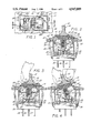
- FIG. 1 is a top plan view of one embodiment of a new and improved three-position safety switch incorporating the unique features of the present invention.
- FIG. 2 is a fragmentary cross-section taken substantially along the line 2--2 of FIG. 1.
- FIGS. 3 and 4 are views generally similar to FIG. 2 but show certain components of the switch being successively moved to place the switch in its first actuated state.
- FIGS. 5 and 6 also are views generally similar to FIG. 2 but show certain components of the switch being successively moved to place the switch in its second actuated state.
- FIG. 7 is an exploded perspective view of certain components of the switch.
- FIGS. 8, 9 and 10 are views corresponding generally to FIGS. 2, 3 and 4, respectively, but show a modified version of the switch.
- the present invention has been shown in the drawings as being incorporated in a three-position electrical switch 20 for making or breaking circuits to one or more electrical utilization devices (not shown).
- the utilization device may be an electrically powered radiant space heater.
- the switch may be used to turn the heater to a high setting, to turn the heater to a low setting or to turn the heater off.
- the switch 20 has been shown in conjunction with a mounting plate 21 which is formed with a rectangular hole 22 for receiving the switch.
- the switch includes a main body or housing which is defined by a molded plastic cup 24 (FIG. 2) of rectangular cross-section telescoped into the opening 22 and formed with a peripheral flange 25 which engages the upper side of the plate around the margins of the opening.
- Cantilevered fingers 26 are molded integrally with and are hinged to the cup 24 and are adapted to pass through the opening 22 during insertion of the cup into the opening. Just after such insertion, the fingers 26 spring outwardly and engage the lower portion of the edge of the opening 22 so as to hold the cup 24 in the opening.
- switch contacts 31, 32 and 33 Located in the bottom of the cup 24 are three spaced switch contacts 31, 32 and 33 (FIG. 2) connected to terminals 34, 35 and 36, respectively.
- an electrically conductive contactor arm 37 Positioned above the contacts is an electrically conductive contactor arm 37 whose opposite end portions define contacts 38 and 39 which are adapted to engage the contacts 31 and 32, respectively.
- the center portion of the contact arm 37 is defined by a dimple 37A which is cradled by the center contact 33.
- the contactor arm 37 When the contactor arm 37 is slid from left-to-right from the position shown in FIG. 2, it pivots clockwise about the center contact 33 to bring the contact 39 downwardly into engagement with the contact 32, the arm thereby bridging the contacts 32 and 33 as shown in FIG. 4 and completing, for example, the high heat circuit of the heater. Conversely, right-to-left sliding of the contactor arm 37 causes the arm to pivot counterclockwise about the center contact 33 in order to bring the contact 38 into engagement with the contact 31 (see FIG. 6) and energize the low heat circuit of the heater.
- rocker-type actuator 40 which is supported by the cup 24 to pivot counterclockwise from a neutral position (FIG. 2) to a first actuated position (FIG. 4) and to pivot clockwise from the neutral position to a second actuated position (FIG. 6).
- the rocker 40 is molded of plastic and is formed with two oppositely extending pins 41 (FIG. 7) which project through circular holes in the cup 24 to support the rocker for pivoting about a horizontal axis.
- the rocker is formed with a generally vertical sleeve 43 which houses a spring 44 and a plunger 45, the spring biasing the plunger downwardly against the contactor arm 37.
- the spring presses the plunger downwardly into the dimple 37A in the central portion of the arm 37 and holds the arm in a horizontal position on the contact 33 so as to keep the contacts 38 and 39 out of engagement with the contacts 31 and 32.
- the three-position switch 20 is provided with a relatively simple and inexpensive latch 50 which prevents the switch rocker 40 from being actuated to either of its switch-closed states unless two separate and distinct motions are applied to the switch.
- the latch releasably holds the rocker in each of its switch-closed states and enables the switch to be de-actuated or opened from either of its closed states with a simple single motion.
- the switch 20 is truly a safety switch in that a conscious effort involving separate motions is required for actuation so as to prevent accidental closing of the switch and yet, at the same time, the switch may be quickly opened under an emergency condition and may be opened easily under normal conditions.
- the latch 50 includes a plate 51 molded of plastic and formed with a central and upwardly projecting handle 52.
- the plate overlies the upper end of the rocker 40.
- Formed integrally with and depending from the plate are two laterally spaced ears 52A (FIGS. 2 and 7) which straddle the rocker 40.
- Each ear is formed with an elongated and generally horizontal slot 53 which receives the adjacent pin 41 with a sliding fit.
- the pins and slots mount the latch 50 for back and forth sliding on the rocker 40 from a centered latched position (FIG. 2) to a rightwardly located first unlatched position (FIG. 3) and from the centered position to a leftwardly located second unlatched position (FIG. 5).
- the latch 50 is biased to and is normally held in its centered latched position by a pair of coiled compression springs 55. As shown most clearly in FIG. 7, the springs are received in two side-by-side and upwardly opening pockets 58 formed in the upper side of the rocker 40. In addition, the springs are received in two aligned pockets 60 formed in and opening downwardly out of the lower side of the plate 51 of the latch 50. The ends of the springs normally engage the ends of the pockets 58 and normally engage left and right abutments 61 and 62 formed adjacent the left and right ends, respectively, of the pockets 60. As a result of such engagement, the springs 57 normally hold the latch 50 in its latched position and keep the latch centered with respect to the cup 24 and the rocker 40.
- left and right noses 70 and 71 defined at the left and right ends, respectively, of the latch plate 51 overlie the flange 25 of the cup 24.
- the nose 70 engages the flange 25 to prevent the rocker 40 from being pivoted counterclockwise to its first actuated position while the nose 71 engages the flange to prevent the rocker from being pivoted clockwise to its second actuated position. Accordingly, it is not possible to pivot the actuator in either direction by merely applying a simple pivoting force to the handle 52 of the latch 50.
- the handle 52 of the latch 50 is engaged by a forefinger or is gripped between a thumb and a forefinger and is slid to the right to its first unlatched position as permitted by the pins 41 and the slots 53 (see FIG. 3).
- the left abutments 61 in the pockets 60 engage the springs 57 and compress the springs against the right end walls of the pockets 58.
- the handle 52 may be swung counterclockwise as shown in FIG. 4 to enable the rocker 40 to pivot to a position closing the contacts 32 and 39.
- Movement of the rocker from its neutral position of FIG. 2 to its actuated position of FIG. 6 is accomplished in a similar but reverse manner.
- the latch 50 first is pushed to the left as shown in FIG. 5 to cause the abutments 62 to load the springs 57 and to shift the nose 71 clear of the flange 25.
- the rocker 40 is pivoted clockwise to the position shown in FIG. 6 and, when the handle 52 is released, the nose 71 snaps into frictional engagement with the inner wall of the cup 24 in order to hold the rocker releasably in its actuated position.
- the rocker 40 may be returned from either of its actuated positions simply by gripping the handle 52 and pivoting the handle in the appropriate direction. This overcomes the frictional resistance of the nose 70, 71 against the cup 24 and allows the rocker to return to its neutral position. Once the nose 70, 71 has moved out of the cup 24, the springs 57 automatically slide the latch 50 to its latched position. Thus, only a simple single motion is required to de-actuate the switch 20.
- FIGS. 8 to 10 A slightly modified switch 20' has been shown in FIGS. 8 to 10 and is a simple two-position on-off switch. The "off" position has been shown in FIG. 8 while FIG. 10 shows the "on” position.
- FIG. 9 shows the latch 50' being shifted to its unlatched position preparatory to the rocker 40' being pivoted to the actuated position of FIG. 10.
- the switch 20' and the switch 20 are identical except that the switch 20' does not include a contact and terminal similar to the contact 31 and the terminal 34 of the switch 20. Instead, the inside of the cup 24' of the switch 20' is formed with a raised ledge 80 which supports the contactor arm 37' when the rocker 40' is in its "off" position shown in FIG. 8.
Abstract
Description
Claims (3)
Priority Applications (1)
| Application Number | Priority Date | Filing Date | Title |
|---|---|---|---|
| US07/401,944 US4947009A (en) | 1987-10-28 | 1989-09-01 | Conscious effort safety switch |
Applications Claiming Priority (3)
| Application Number | Priority Date | Filing Date | Title |
|---|---|---|---|
| US07/114,129 US4870230A (en) | 1987-10-28 | 1987-10-28 | Safety rocker |
| US30873489A | 1989-02-09 | 1989-02-09 | |
| US07/401,944 US4947009A (en) | 1987-10-28 | 1989-09-01 | Conscious effort safety switch |
Related Parent Applications (1)
| Application Number | Title | Priority Date | Filing Date |
|---|---|---|---|
| US30873489A Continuation-In-Part | 1987-10-28 | 1989-02-09 |
Publications (1)
| Publication Number | Publication Date |
|---|---|
| US4947009A true US4947009A (en) | 1990-08-07 |
Family
ID=27381452
Family Applications (1)
| Application Number | Title | Priority Date | Filing Date |
|---|---|---|---|
| US07/401,944 Expired - Fee Related US4947009A (en) | 1987-10-28 | 1989-09-01 | Conscious effort safety switch |
Country Status (1)
| Country | Link |
|---|---|
| US (1) | US4947009A (en) |
Cited By (101)
| Publication number | Priority date | Publication date | Assignee | Title |
|---|---|---|---|---|
| US5041706A (en) * | 1990-04-26 | 1991-08-20 | Mcgill Manufacturing Company, Inc. | Safety switch with positive mounting retention and prolonged opening characteristics |
| US5045648A (en) * | 1990-03-23 | 1991-09-03 | Eaton Corporation | Locking rocker switch |
| US5095181A (en) * | 1987-10-28 | 1992-03-10 | Mcgill Manufacturing Company, Inc. | Three-position safety rocker |
| US5380964A (en) * | 1993-10-18 | 1995-01-10 | Deere & Company | Switch assembly |
| US6549113B1 (en) * | 2000-09-14 | 2003-04-15 | Eaton Corporation | Sealed electric switch |
| US6675733B2 (en) * | 2000-10-31 | 2004-01-13 | Nhk Morse Co., Ltd. | Remote control device for small vessel |
| US20050066765A1 (en) * | 2003-09-26 | 2005-03-31 | Toshiya Otani | Operation lever structure |
| FR2861213A1 (en) * | 2003-10-16 | 2005-04-22 | Legrand Sa | Electrical circuit switch has lockable toggle enabling it to be fixed in e.g. 'off' position for security |
| US20080053804A1 (en) * | 2006-09-05 | 2008-03-06 | Defond Components Limited | Electrical switch |
| EP1956619A1 (en) | 2007-02-08 | 2008-08-13 | Apem | Locking switch |
| US20080249527A1 (en) * | 2007-04-04 | 2008-10-09 | Tyco Healthcare Group Lp | Electrosurgical instrument reducing current densities at an insulator conductor junction |
| FR2927432A1 (en) * | 2008-02-07 | 2009-08-14 | Renault Sas | Opening frame's i.e. motorized boot opening frame, opening control device for motor vehicle, has activating element moving between rest position and control position according to complex movement with two degrees of freedom |
| US7708735B2 (en) | 2003-05-01 | 2010-05-04 | Covidien Ag | Incorporating rapid cooling in tissue fusion heating processes |
| US7722607B2 (en) | 2005-09-30 | 2010-05-25 | Covidien Ag | In-line vessel sealer and divider |
| US7771425B2 (en) | 2003-06-13 | 2010-08-10 | Covidien Ag | Vessel sealer and divider having a variable jaw clamping mechanism |
| US7776037B2 (en) | 2006-07-07 | 2010-08-17 | Covidien Ag | System and method for controlling electrode gap during tissue sealing |
| US7776036B2 (en) | 2003-03-13 | 2010-08-17 | Covidien Ag | Bipolar concentric electrode assembly for soft tissue fusion |
| US7789878B2 (en) | 2005-09-30 | 2010-09-07 | Covidien Ag | In-line vessel sealer and divider |
| US7799028B2 (en) | 2004-09-21 | 2010-09-21 | Covidien Ag | Articulating bipolar electrosurgical instrument |
| US7799026B2 (en) | 2002-11-14 | 2010-09-21 | Covidien Ag | Compressible jaw configuration with bipolar RF output electrodes for soft tissue fusion |
| US7811283B2 (en) | 2003-11-19 | 2010-10-12 | Covidien Ag | Open vessel sealing instrument with hourglass cutting mechanism and over-ratchet safety |
| US7828798B2 (en) | 1997-11-14 | 2010-11-09 | Covidien Ag | Laparoscopic bipolar electrosurgical instrument |
| US7846161B2 (en) | 2005-09-30 | 2010-12-07 | Covidien Ag | Insulating boot for electrosurgical forceps |
| US7857812B2 (en) | 2003-06-13 | 2010-12-28 | Covidien Ag | Vessel sealer and divider having elongated knife stroke and safety for cutting mechanism |
| US7879035B2 (en) | 2005-09-30 | 2011-02-01 | Covidien Ag | Insulating boot for electrosurgical forceps |
| US7887536B2 (en) | 1998-10-23 | 2011-02-15 | Covidien Ag | Vessel sealing instrument |
| US7909823B2 (en) | 2005-01-14 | 2011-03-22 | Covidien Ag | Open vessel sealing instrument |
| US7922718B2 (en) | 2003-11-19 | 2011-04-12 | Covidien Ag | Open vessel sealing instrument with cutting mechanism |
| US7922953B2 (en) | 2005-09-30 | 2011-04-12 | Covidien Ag | Method for manufacturing an end effector assembly |
| US7931649B2 (en) | 2002-10-04 | 2011-04-26 | Tyco Healthcare Group Lp | Vessel sealing instrument with electrical cutting mechanism |
| US7935052B2 (en) | 2004-09-09 | 2011-05-03 | Covidien Ag | Forceps with spring loaded end effector assembly |
| US7947041B2 (en) | 1998-10-23 | 2011-05-24 | Covidien Ag | Vessel sealing instrument |
| US7951150B2 (en) | 2005-01-14 | 2011-05-31 | Covidien Ag | Vessel sealer and divider with rotating sealer and cutter |
| US7955332B2 (en) | 2004-10-08 | 2011-06-07 | Covidien Ag | Mechanism for dividing tissue in a hemostat-style instrument |
| US7963965B2 (en) | 1997-11-12 | 2011-06-21 | Covidien Ag | Bipolar electrosurgical instrument for sealing vessels |
| US8016827B2 (en) | 2008-10-09 | 2011-09-13 | Tyco Healthcare Group Lp | Apparatus, system, and method for performing an electrosurgical procedure |
| USD649249S1 (en) | 2007-02-15 | 2011-11-22 | Tyco Healthcare Group Lp | End effectors of an elongated dissecting and dividing instrument |
| US8070746B2 (en) | 2006-10-03 | 2011-12-06 | Tyco Healthcare Group Lp | Radiofrequency fusion of cardiac tissue |
| US8142473B2 (en) | 2008-10-03 | 2012-03-27 | Tyco Healthcare Group Lp | Method of transferring rotational motion in an articulating surgical instrument |
| US8162973B2 (en) | 2008-08-15 | 2012-04-24 | Tyco Healthcare Group Lp | Method of transferring pressure in an articulating surgical instrument |
| US8162940B2 (en) | 2002-10-04 | 2012-04-24 | Covidien Ag | Vessel sealing instrument with electrical cutting mechanism |
| US8192433B2 (en) | 2002-10-04 | 2012-06-05 | Covidien Ag | Vessel sealing instrument with electrical cutting mechanism |
| US8197479B2 (en) | 2008-12-10 | 2012-06-12 | Tyco Healthcare Group Lp | Vessel sealer and divider |
| US8211105B2 (en) | 1997-11-12 | 2012-07-03 | Covidien Ag | Electrosurgical instrument which reduces collateral damage to adjacent tissue |
| US8221416B2 (en) | 2007-09-28 | 2012-07-17 | Tyco Healthcare Group Lp | Insulating boot for electrosurgical forceps with thermoplastic clevis |
| US8235992B2 (en) | 2007-09-28 | 2012-08-07 | Tyco Healthcare Group Lp | Insulating boot with mechanical reinforcement for electrosurgical forceps |
| US8235993B2 (en) | 2007-09-28 | 2012-08-07 | Tyco Healthcare Group Lp | Insulating boot for electrosurgical forceps with exohinged structure |
| US8236025B2 (en) | 2007-09-28 | 2012-08-07 | Tyco Healthcare Group Lp | Silicone insulated electrosurgical forceps |
| US8241284B2 (en) | 2001-04-06 | 2012-08-14 | Covidien Ag | Vessel sealer and divider with non-conductive stop members |
| US8241283B2 (en) | 2007-09-28 | 2012-08-14 | Tyco Healthcare Group Lp | Dual durometer insulating boot for electrosurgical forceps |
| US8241282B2 (en) | 2006-01-24 | 2012-08-14 | Tyco Healthcare Group Lp | Vessel sealing cutting assemblies |
| US8251996B2 (en) | 2007-09-28 | 2012-08-28 | Tyco Healthcare Group Lp | Insulating sheath for electrosurgical forceps |
| US8257352B2 (en) | 2003-11-17 | 2012-09-04 | Covidien Ag | Bipolar forceps having monopolar extension |
| US8257387B2 (en) | 2008-08-15 | 2012-09-04 | Tyco Healthcare Group Lp | Method of transferring pressure in an articulating surgical instrument |
| US8267936B2 (en) | 2007-09-28 | 2012-09-18 | Tyco Healthcare Group Lp | Insulating mechanically-interfaced adhesive for electrosurgical forceps |
| US8298232B2 (en) | 2006-01-24 | 2012-10-30 | Tyco Healthcare Group Lp | Endoscopic vessel sealer and divider for large tissue structures |
| US8298228B2 (en) | 1997-11-12 | 2012-10-30 | Coviden Ag | Electrosurgical instrument which reduces collateral damage to adjacent tissue |
| US8303586B2 (en) | 2003-11-19 | 2012-11-06 | Covidien Ag | Spring loaded reciprocating tissue cutting mechanism in a forceps-style electrosurgical instrument |
| US8303582B2 (en) | 2008-09-15 | 2012-11-06 | Tyco Healthcare Group Lp | Electrosurgical instrument having a coated electrode utilizing an atomic layer deposition technique |
| US8317787B2 (en) | 2008-08-28 | 2012-11-27 | Covidien Lp | Tissue fusion jaw angle improvement |
| US8348948B2 (en) | 2004-03-02 | 2013-01-08 | Covidien Ag | Vessel sealing system using capacitive RF dielectric heating |
| US8361071B2 (en) | 1999-10-22 | 2013-01-29 | Covidien Ag | Vessel sealing forceps with disposable electrodes |
| US8382754B2 (en) | 2005-03-31 | 2013-02-26 | Covidien Ag | Electrosurgical forceps with slow closure sealing plates and method of sealing tissue |
| USD680220S1 (en) | 2012-01-12 | 2013-04-16 | Coviden IP | Slider handle for laparoscopic device |
| US8454602B2 (en) | 2009-05-07 | 2013-06-04 | Covidien Lp | Apparatus, system, and method for performing an electrosurgical procedure |
| US8469957B2 (en) | 2008-10-07 | 2013-06-25 | Covidien Lp | Apparatus, system, and method for performing an electrosurgical procedure |
| US8469956B2 (en) | 2008-07-21 | 2013-06-25 | Covidien Lp | Variable resistor jaw |
| US8486107B2 (en) | 2008-10-20 | 2013-07-16 | Covidien Lp | Method of sealing tissue using radiofrequency energy |
| US8496656B2 (en) | 2003-05-15 | 2013-07-30 | Covidien Ag | Tissue sealer with non-conductive variable stop members and method of sealing tissue |
| US8523898B2 (en) | 2009-07-08 | 2013-09-03 | Covidien Lp | Endoscopic electrosurgical jaws with offset knife |
| US8535312B2 (en) | 2008-09-25 | 2013-09-17 | Covidien Lp | Apparatus, system and method for performing an electrosurgical procedure |
| US8591506B2 (en) | 1998-10-23 | 2013-11-26 | Covidien Ag | Vessel sealing system |
| US8597297B2 (en) | 2006-08-29 | 2013-12-03 | Covidien Ag | Vessel sealing instrument with multiple electrode configurations |
| US8623276B2 (en) | 2008-02-15 | 2014-01-07 | Covidien Lp | Method and system for sterilizing an electrosurgical instrument |
| US8636761B2 (en) | 2008-10-09 | 2014-01-28 | Covidien Lp | Apparatus, system, and method for performing an endoscopic electrosurgical procedure |
| US8641713B2 (en) | 2005-09-30 | 2014-02-04 | Covidien Ag | Flexible endoscopic catheter with ligasure |
| US8647341B2 (en) | 2003-06-13 | 2014-02-11 | Covidien Ag | Vessel sealer and divider for use with small trocars and cannulas |
| US8734443B2 (en) | 2006-01-24 | 2014-05-27 | Covidien Lp | Vessel sealer and divider for large tissue structures |
| US8764748B2 (en) | 2008-02-06 | 2014-07-01 | Covidien Lp | End effector assembly for electrosurgical device and method for making the same |
| US8784417B2 (en) | 2008-08-28 | 2014-07-22 | Covidien Lp | Tissue fusion jaw angle improvement |
| US8795274B2 (en) | 2008-08-28 | 2014-08-05 | Covidien Lp | Tissue fusion jaw angle improvement |
| US8852228B2 (en) | 2009-01-13 | 2014-10-07 | Covidien Lp | Apparatus, system, and method for performing an electrosurgical procedure |
| US8882766B2 (en) | 2006-01-24 | 2014-11-11 | Covidien Ag | Method and system for controlling delivery of energy to divide tissue |
| US8898888B2 (en) | 2009-09-28 | 2014-12-02 | Covidien Lp | System for manufacturing electrosurgical seal plates |
| US8968314B2 (en) | 2008-09-25 | 2015-03-03 | Covidien Lp | Apparatus, system and method for performing an electrosurgical procedure |
| US9023043B2 (en) | 2007-09-28 | 2015-05-05 | Covidien Lp | Insulating mechanically-interfaced boot and jaws for electrosurgical forceps |
| US9028493B2 (en) | 2009-09-18 | 2015-05-12 | Covidien Lp | In vivo attachable and detachable end effector assembly and laparoscopic surgical instrument and methods therefor |
| US9095347B2 (en) | 2003-11-20 | 2015-08-04 | Covidien Ag | Electrically conductive/insulative over shoe for tissue fusion |
| US9107672B2 (en) | 1998-10-23 | 2015-08-18 | Covidien Ag | Vessel sealing forceps with disposable electrodes |
| US9113940B2 (en) | 2011-01-14 | 2015-08-25 | Covidien Lp | Trigger lockout and kickback mechanism for surgical instruments |
| US9149323B2 (en) | 2003-05-01 | 2015-10-06 | Covidien Ag | Method of fusing biomaterials with radiofrequency energy |
| US9375254B2 (en) | 2008-09-25 | 2016-06-28 | Covidien Lp | Seal and separate algorithm |
| US20170040130A1 (en) * | 2014-03-28 | 2017-02-09 | Yaowu Hua | Time switch of controllable time adjustment |
| US9603652B2 (en) | 2008-08-21 | 2017-03-28 | Covidien Lp | Electrosurgical instrument including a sensor |
| US9848938B2 (en) | 2003-11-13 | 2017-12-26 | Covidien Ag | Compressible jaw configuration with bipolar RF output electrodes for soft tissue fusion |
| US10213250B2 (en) | 2015-11-05 | 2019-02-26 | Covidien Lp | Deployment and safety mechanisms for surgical instruments |
| US10646267B2 (en) | 2013-08-07 | 2020-05-12 | Covidien LLP | Surgical forceps |
| US10987159B2 (en) | 2015-08-26 | 2021-04-27 | Covidien Lp | Electrosurgical end effector assemblies and electrosurgical forceps configured to reduce thermal spread |
| US11166759B2 (en) | 2017-05-16 | 2021-11-09 | Covidien Lp | Surgical forceps |
| US11189447B2 (en) * | 2014-03-28 | 2021-11-30 | Yaowu Hua | Time switch of controllable time adjustment |
| USD956973S1 (en) | 2003-06-13 | 2022-07-05 | Covidien Ag | Movable handle for endoscopic vessel sealer and divider |
Citations (3)
| Publication number | Priority date | Publication date | Assignee | Title |
|---|---|---|---|---|
| US4002874A (en) * | 1975-03-19 | 1977-01-11 | Cutler-Hammer, Inc. | Double-throw rocker switch with selective lockout means |
| US4121065A (en) * | 1977-10-31 | 1978-10-17 | Cutler-Hammer, Inc. | Toggle switch lever lock |
| US4187420A (en) * | 1978-05-17 | 1980-02-05 | Eaton Corporation | Rocker switch with selective lockout means shiftable transversely of the pivotal axis |
-
1989
- 1989-09-01 US US07/401,944 patent/US4947009A/en not_active Expired - Fee Related
Patent Citations (3)
| Publication number | Priority date | Publication date | Assignee | Title |
|---|---|---|---|---|
| US4002874A (en) * | 1975-03-19 | 1977-01-11 | Cutler-Hammer, Inc. | Double-throw rocker switch with selective lockout means |
| US4121065A (en) * | 1977-10-31 | 1978-10-17 | Cutler-Hammer, Inc. | Toggle switch lever lock |
| US4187420A (en) * | 1978-05-17 | 1980-02-05 | Eaton Corporation | Rocker switch with selective lockout means shiftable transversely of the pivotal axis |
Cited By (161)
| Publication number | Priority date | Publication date | Assignee | Title |
|---|---|---|---|---|
| US5095181A (en) * | 1987-10-28 | 1992-03-10 | Mcgill Manufacturing Company, Inc. | Three-position safety rocker |
| US5045648A (en) * | 1990-03-23 | 1991-09-03 | Eaton Corporation | Locking rocker switch |
| US5041706A (en) * | 1990-04-26 | 1991-08-20 | Mcgill Manufacturing Company, Inc. | Safety switch with positive mounting retention and prolonged opening characteristics |
| US5380964A (en) * | 1993-10-18 | 1995-01-10 | Deere & Company | Switch assembly |
| US8211105B2 (en) | 1997-11-12 | 2012-07-03 | Covidien Ag | Electrosurgical instrument which reduces collateral damage to adjacent tissue |
| US7963965B2 (en) | 1997-11-12 | 2011-06-21 | Covidien Ag | Bipolar electrosurgical instrument for sealing vessels |
| US8298228B2 (en) | 1997-11-12 | 2012-10-30 | Coviden Ag | Electrosurgical instrument which reduces collateral damage to adjacent tissue |
| US7828798B2 (en) | 1997-11-14 | 2010-11-09 | Covidien Ag | Laparoscopic bipolar electrosurgical instrument |
| US9375271B2 (en) | 1998-10-23 | 2016-06-28 | Covidien Ag | Vessel sealing system |
| US8591506B2 (en) | 1998-10-23 | 2013-11-26 | Covidien Ag | Vessel sealing system |
| US9463067B2 (en) | 1998-10-23 | 2016-10-11 | Covidien Ag | Vessel sealing system |
| US7947041B2 (en) | 1998-10-23 | 2011-05-24 | Covidien Ag | Vessel sealing instrument |
| US7896878B2 (en) | 1998-10-23 | 2011-03-01 | Coviden Ag | Vessel sealing instrument |
| US9375270B2 (en) | 1998-10-23 | 2016-06-28 | Covidien Ag | Vessel sealing system |
| US9107672B2 (en) | 1998-10-23 | 2015-08-18 | Covidien Ag | Vessel sealing forceps with disposable electrodes |
| US7887536B2 (en) | 1998-10-23 | 2011-02-15 | Covidien Ag | Vessel sealing instrument |
| US8361071B2 (en) | 1999-10-22 | 2013-01-29 | Covidien Ag | Vessel sealing forceps with disposable electrodes |
| US6549113B1 (en) * | 2000-09-14 | 2003-04-15 | Eaton Corporation | Sealed electric switch |
| US6675733B2 (en) * | 2000-10-31 | 2004-01-13 | Nhk Morse Co., Ltd. | Remote control device for small vessel |
| US8241284B2 (en) | 2001-04-06 | 2012-08-14 | Covidien Ag | Vessel sealer and divider with non-conductive stop members |
| US10687887B2 (en) | 2001-04-06 | 2020-06-23 | Covidien Ag | Vessel sealer and divider |
| US10265121B2 (en) | 2001-04-06 | 2019-04-23 | Covidien Ag | Vessel sealer and divider |
| US10251696B2 (en) | 2001-04-06 | 2019-04-09 | Covidien Ag | Vessel sealer and divider with stop members |
| US9585716B2 (en) | 2002-10-04 | 2017-03-07 | Covidien Ag | Vessel sealing instrument with electrical cutting mechanism |
| US8740901B2 (en) | 2002-10-04 | 2014-06-03 | Covidien Ag | Vessel sealing instrument with electrical cutting mechanism |
| US10987160B2 (en) | 2002-10-04 | 2021-04-27 | Covidien Ag | Vessel sealing instrument with cutting mechanism |
| US8192433B2 (en) | 2002-10-04 | 2012-06-05 | Covidien Ag | Vessel sealing instrument with electrical cutting mechanism |
| US8551091B2 (en) | 2002-10-04 | 2013-10-08 | Covidien Ag | Vessel sealing instrument with electrical cutting mechanism |
| US10537384B2 (en) | 2002-10-04 | 2020-01-21 | Covidien Lp | Vessel sealing instrument with electrical cutting mechanism |
| US8162940B2 (en) | 2002-10-04 | 2012-04-24 | Covidien Ag | Vessel sealing instrument with electrical cutting mechanism |
| US8333765B2 (en) | 2002-10-04 | 2012-12-18 | Covidien Ag | Vessel sealing instrument with electrical cutting mechanism |
| US7931649B2 (en) | 2002-10-04 | 2011-04-26 | Tyco Healthcare Group Lp | Vessel sealing instrument with electrical cutting mechanism |
| US7799026B2 (en) | 2002-11-14 | 2010-09-21 | Covidien Ag | Compressible jaw configuration with bipolar RF output electrodes for soft tissue fusion |
| US8945125B2 (en) | 2002-11-14 | 2015-02-03 | Covidien Ag | Compressible jaw configuration with bipolar RF output electrodes for soft tissue fusion |
| US7776036B2 (en) | 2003-03-13 | 2010-08-17 | Covidien Ag | Bipolar concentric electrode assembly for soft tissue fusion |
| US7708735B2 (en) | 2003-05-01 | 2010-05-04 | Covidien Ag | Incorporating rapid cooling in tissue fusion heating processes |
| US9149323B2 (en) | 2003-05-01 | 2015-10-06 | Covidien Ag | Method of fusing biomaterials with radiofrequency energy |
| US8679114B2 (en) | 2003-05-01 | 2014-03-25 | Covidien Ag | Incorporating rapid cooling in tissue fusion heating processes |
| USRE47375E1 (en) | 2003-05-15 | 2019-05-07 | Coviden Ag | Tissue sealer with non-conductive variable stop members and method of sealing tissue |
| US8496656B2 (en) | 2003-05-15 | 2013-07-30 | Covidien Ag | Tissue sealer with non-conductive variable stop members and method of sealing tissue |
| US9492225B2 (en) | 2003-06-13 | 2016-11-15 | Covidien Ag | Vessel sealer and divider for use with small trocars and cannulas |
| US7857812B2 (en) | 2003-06-13 | 2010-12-28 | Covidien Ag | Vessel sealer and divider having elongated knife stroke and safety for cutting mechanism |
| US10278772B2 (en) | 2003-06-13 | 2019-05-07 | Covidien Ag | Vessel sealer and divider |
| US8647341B2 (en) | 2003-06-13 | 2014-02-11 | Covidien Ag | Vessel sealer and divider for use with small trocars and cannulas |
| USD956973S1 (en) | 2003-06-13 | 2022-07-05 | Covidien Ag | Movable handle for endoscopic vessel sealer and divider |
| US10918435B2 (en) | 2003-06-13 | 2021-02-16 | Covidien Ag | Vessel sealer and divider |
| US10842553B2 (en) | 2003-06-13 | 2020-11-24 | Covidien Ag | Vessel sealer and divider |
| US7771425B2 (en) | 2003-06-13 | 2010-08-10 | Covidien Ag | Vessel sealer and divider having a variable jaw clamping mechanism |
| US20050066765A1 (en) * | 2003-09-26 | 2005-03-31 | Toshiya Otani | Operation lever structure |
| FR2861213A1 (en) * | 2003-10-16 | 2005-04-22 | Legrand Sa | Electrical circuit switch has lockable toggle enabling it to be fixed in e.g. 'off' position for security |
| US9848938B2 (en) | 2003-11-13 | 2017-12-26 | Covidien Ag | Compressible jaw configuration with bipolar RF output electrodes for soft tissue fusion |
| US8597296B2 (en) | 2003-11-17 | 2013-12-03 | Covidien Ag | Bipolar forceps having monopolar extension |
| US10441350B2 (en) | 2003-11-17 | 2019-10-15 | Covidien Ag | Bipolar forceps having monopolar extension |
| US8257352B2 (en) | 2003-11-17 | 2012-09-04 | Covidien Ag | Bipolar forceps having monopolar extension |
| US7922718B2 (en) | 2003-11-19 | 2011-04-12 | Covidien Ag | Open vessel sealing instrument with cutting mechanism |
| US8394096B2 (en) | 2003-11-19 | 2013-03-12 | Covidien Ag | Open vessel sealing instrument with cutting mechanism |
| US7811283B2 (en) | 2003-11-19 | 2010-10-12 | Covidien Ag | Open vessel sealing instrument with hourglass cutting mechanism and over-ratchet safety |
| US8303586B2 (en) | 2003-11-19 | 2012-11-06 | Covidien Ag | Spring loaded reciprocating tissue cutting mechanism in a forceps-style electrosurgical instrument |
| US8623017B2 (en) | 2003-11-19 | 2014-01-07 | Covidien Ag | Open vessel sealing instrument with hourglass cutting mechanism and overratchet safety |
| US9980770B2 (en) | 2003-11-20 | 2018-05-29 | Covidien Ag | Electrically conductive/insulative over-shoe for tissue fusion |
| US9095347B2 (en) | 2003-11-20 | 2015-08-04 | Covidien Ag | Electrically conductive/insulative over shoe for tissue fusion |
| US8348948B2 (en) | 2004-03-02 | 2013-01-08 | Covidien Ag | Vessel sealing system using capacitive RF dielectric heating |
| US7935052B2 (en) | 2004-09-09 | 2011-05-03 | Covidien Ag | Forceps with spring loaded end effector assembly |
| US7799028B2 (en) | 2004-09-21 | 2010-09-21 | Covidien Ag | Articulating bipolar electrosurgical instrument |
| US8366709B2 (en) | 2004-09-21 | 2013-02-05 | Covidien Ag | Articulating bipolar electrosurgical instrument |
| US8123743B2 (en) | 2004-10-08 | 2012-02-28 | Covidien Ag | Mechanism for dividing tissue in a hemostat-style instrument |
| US7955332B2 (en) | 2004-10-08 | 2011-06-07 | Covidien Ag | Mechanism for dividing tissue in a hemostat-style instrument |
| US7909823B2 (en) | 2005-01-14 | 2011-03-22 | Covidien Ag | Open vessel sealing instrument |
| US8147489B2 (en) | 2005-01-14 | 2012-04-03 | Covidien Ag | Open vessel sealing instrument |
| US20110196368A1 (en) * | 2005-01-14 | 2011-08-11 | Covidien Ag | Open Vessel Sealing Instrument |
| US7951150B2 (en) | 2005-01-14 | 2011-05-31 | Covidien Ag | Vessel sealer and divider with rotating sealer and cutter |
| US8382754B2 (en) | 2005-03-31 | 2013-02-26 | Covidien Ag | Electrosurgical forceps with slow closure sealing plates and method of sealing tissue |
| USRE44834E1 (en) | 2005-09-30 | 2014-04-08 | Covidien Ag | Insulating boot for electrosurgical forceps |
| US7922953B2 (en) | 2005-09-30 | 2011-04-12 | Covidien Ag | Method for manufacturing an end effector assembly |
| US8361072B2 (en) | 2005-09-30 | 2013-01-29 | Covidien Ag | Insulating boot for electrosurgical forceps |
| US8668689B2 (en) | 2005-09-30 | 2014-03-11 | Covidien Ag | In-line vessel sealer and divider |
| US9549775B2 (en) | 2005-09-30 | 2017-01-24 | Covidien Ag | In-line vessel sealer and divider |
| US9579145B2 (en) | 2005-09-30 | 2017-02-28 | Covidien Ag | Flexible endoscopic catheter with ligasure |
| US8394095B2 (en) | 2005-09-30 | 2013-03-12 | Covidien Ag | Insulating boot for electrosurgical forceps |
| US7879035B2 (en) | 2005-09-30 | 2011-02-01 | Covidien Ag | Insulating boot for electrosurgical forceps |
| US8641713B2 (en) | 2005-09-30 | 2014-02-04 | Covidien Ag | Flexible endoscopic catheter with ligasure |
| US7846161B2 (en) | 2005-09-30 | 2010-12-07 | Covidien Ag | Insulating boot for electrosurgical forceps |
| US8197633B2 (en) | 2005-09-30 | 2012-06-12 | Covidien Ag | Method for manufacturing an end effector assembly |
| US7789878B2 (en) | 2005-09-30 | 2010-09-07 | Covidien Ag | In-line vessel sealer and divider |
| US7722607B2 (en) | 2005-09-30 | 2010-05-25 | Covidien Ag | In-line vessel sealer and divider |
| US9113903B2 (en) | 2006-01-24 | 2015-08-25 | Covidien Lp | Endoscopic vessel sealer and divider for large tissue structures |
| US9539053B2 (en) | 2006-01-24 | 2017-01-10 | Covidien Lp | Vessel sealer and divider for large tissue structures |
| US8241282B2 (en) | 2006-01-24 | 2012-08-14 | Tyco Healthcare Group Lp | Vessel sealing cutting assemblies |
| US8882766B2 (en) | 2006-01-24 | 2014-11-11 | Covidien Ag | Method and system for controlling delivery of energy to divide tissue |
| US9918782B2 (en) | 2006-01-24 | 2018-03-20 | Covidien Lp | Endoscopic vessel sealer and divider for large tissue structures |
| US8734443B2 (en) | 2006-01-24 | 2014-05-27 | Covidien Lp | Vessel sealer and divider for large tissue structures |
| US8298232B2 (en) | 2006-01-24 | 2012-10-30 | Tyco Healthcare Group Lp | Endoscopic vessel sealer and divider for large tissue structures |
| US7776037B2 (en) | 2006-07-07 | 2010-08-17 | Covidien Ag | System and method for controlling electrode gap during tissue sealing |
| US8597297B2 (en) | 2006-08-29 | 2013-12-03 | Covidien Ag | Vessel sealing instrument with multiple electrode configurations |
| US20080053804A1 (en) * | 2006-09-05 | 2008-03-06 | Defond Components Limited | Electrical switch |
| US7468492B2 (en) * | 2006-09-05 | 2008-12-23 | Defond Components Limited | Electrical switch |
| US8070746B2 (en) | 2006-10-03 | 2011-12-06 | Tyco Healthcare Group Lp | Radiofrequency fusion of cardiac tissue |
| US8425504B2 (en) | 2006-10-03 | 2013-04-23 | Covidien Lp | Radiofrequency fusion of cardiac tissue |
| US7868261B2 (en) | 2007-02-08 | 2011-01-11 | Apem | Locking rocker switch |
| US20080190746A1 (en) * | 2007-02-08 | 2008-08-14 | Joel Gauzin | Locking switch |
| CN101241805B (en) * | 2007-02-08 | 2011-06-01 | Apem公司 | Locking switch |
| FR2912543A1 (en) * | 2007-02-08 | 2008-08-15 | Apem Sa | LOCK SWITCH |
| EP1956619A1 (en) | 2007-02-08 | 2008-08-13 | Apem | Locking switch |
| USD649249S1 (en) | 2007-02-15 | 2011-11-22 | Tyco Healthcare Group Lp | End effectors of an elongated dissecting and dividing instrument |
| US20080249527A1 (en) * | 2007-04-04 | 2008-10-09 | Tyco Healthcare Group Lp | Electrosurgical instrument reducing current densities at an insulator conductor junction |
| US8267935B2 (en) | 2007-04-04 | 2012-09-18 | Tyco Healthcare Group Lp | Electrosurgical instrument reducing current densities at an insulator conductor junction |
| US8235992B2 (en) | 2007-09-28 | 2012-08-07 | Tyco Healthcare Group Lp | Insulating boot with mechanical reinforcement for electrosurgical forceps |
| US9554841B2 (en) | 2007-09-28 | 2017-01-31 | Covidien Lp | Dual durometer insulating boot for electrosurgical forceps |
| US8267936B2 (en) | 2007-09-28 | 2012-09-18 | Tyco Healthcare Group Lp | Insulating mechanically-interfaced adhesive for electrosurgical forceps |
| US8221416B2 (en) | 2007-09-28 | 2012-07-17 | Tyco Healthcare Group Lp | Insulating boot for electrosurgical forceps with thermoplastic clevis |
| US9023043B2 (en) | 2007-09-28 | 2015-05-05 | Covidien Lp | Insulating mechanically-interfaced boot and jaws for electrosurgical forceps |
| US8696667B2 (en) | 2007-09-28 | 2014-04-15 | Covidien Lp | Dual durometer insulating boot for electrosurgical forceps |
| US8235993B2 (en) | 2007-09-28 | 2012-08-07 | Tyco Healthcare Group Lp | Insulating boot for electrosurgical forceps with exohinged structure |
| US8251996B2 (en) | 2007-09-28 | 2012-08-28 | Tyco Healthcare Group Lp | Insulating sheath for electrosurgical forceps |
| US8236025B2 (en) | 2007-09-28 | 2012-08-07 | Tyco Healthcare Group Lp | Silicone insulated electrosurgical forceps |
| US8241283B2 (en) | 2007-09-28 | 2012-08-14 | Tyco Healthcare Group Lp | Dual durometer insulating boot for electrosurgical forceps |
| US8764748B2 (en) | 2008-02-06 | 2014-07-01 | Covidien Lp | End effector assembly for electrosurgical device and method for making the same |
| FR2927432A1 (en) * | 2008-02-07 | 2009-08-14 | Renault Sas | Opening frame's i.e. motorized boot opening frame, opening control device for motor vehicle, has activating element moving between rest position and control position according to complex movement with two degrees of freedom |
| US8623276B2 (en) | 2008-02-15 | 2014-01-07 | Covidien Lp | Method and system for sterilizing an electrosurgical instrument |
| US9247988B2 (en) | 2008-07-21 | 2016-02-02 | Covidien Lp | Variable resistor jaw |
| US9113905B2 (en) | 2008-07-21 | 2015-08-25 | Covidien Lp | Variable resistor jaw |
| US8469956B2 (en) | 2008-07-21 | 2013-06-25 | Covidien Lp | Variable resistor jaw |
| US8162973B2 (en) | 2008-08-15 | 2012-04-24 | Tyco Healthcare Group Lp | Method of transferring pressure in an articulating surgical instrument |
| US8257387B2 (en) | 2008-08-15 | 2012-09-04 | Tyco Healthcare Group Lp | Method of transferring pressure in an articulating surgical instrument |
| US9603652B2 (en) | 2008-08-21 | 2017-03-28 | Covidien Lp | Electrosurgical instrument including a sensor |
| US8795274B2 (en) | 2008-08-28 | 2014-08-05 | Covidien Lp | Tissue fusion jaw angle improvement |
| US8784417B2 (en) | 2008-08-28 | 2014-07-22 | Covidien Lp | Tissue fusion jaw angle improvement |
| US8317787B2 (en) | 2008-08-28 | 2012-11-27 | Covidien Lp | Tissue fusion jaw angle improvement |
| US8303582B2 (en) | 2008-09-15 | 2012-11-06 | Tyco Healthcare Group Lp | Electrosurgical instrument having a coated electrode utilizing an atomic layer deposition technique |
| US9375254B2 (en) | 2008-09-25 | 2016-06-28 | Covidien Lp | Seal and separate algorithm |
| US8968314B2 (en) | 2008-09-25 | 2015-03-03 | Covidien Lp | Apparatus, system and method for performing an electrosurgical procedure |
| US8535312B2 (en) | 2008-09-25 | 2013-09-17 | Covidien Lp | Apparatus, system and method for performing an electrosurgical procedure |
| US8568444B2 (en) | 2008-10-03 | 2013-10-29 | Covidien Lp | Method of transferring rotational motion in an articulating surgical instrument |
| US8142473B2 (en) | 2008-10-03 | 2012-03-27 | Tyco Healthcare Group Lp | Method of transferring rotational motion in an articulating surgical instrument |
| US8469957B2 (en) | 2008-10-07 | 2013-06-25 | Covidien Lp | Apparatus, system, and method for performing an electrosurgical procedure |
| US8636761B2 (en) | 2008-10-09 | 2014-01-28 | Covidien Lp | Apparatus, system, and method for performing an endoscopic electrosurgical procedure |
| US8016827B2 (en) | 2008-10-09 | 2011-09-13 | Tyco Healthcare Group Lp | Apparatus, system, and method for performing an electrosurgical procedure |
| US9113898B2 (en) | 2008-10-09 | 2015-08-25 | Covidien Lp | Apparatus, system, and method for performing an electrosurgical procedure |
| US8486107B2 (en) | 2008-10-20 | 2013-07-16 | Covidien Lp | Method of sealing tissue using radiofrequency energy |
| US8197479B2 (en) | 2008-12-10 | 2012-06-12 | Tyco Healthcare Group Lp | Vessel sealer and divider |
| US8852228B2 (en) | 2009-01-13 | 2014-10-07 | Covidien Lp | Apparatus, system, and method for performing an electrosurgical procedure |
| US9655674B2 (en) | 2009-01-13 | 2017-05-23 | Covidien Lp | Apparatus, system and method for performing an electrosurgical procedure |
| US8858554B2 (en) | 2009-05-07 | 2014-10-14 | Covidien Lp | Apparatus, system, and method for performing an electrosurgical procedure |
| US10085794B2 (en) | 2009-05-07 | 2018-10-02 | Covidien Lp | Apparatus, system and method for performing an electrosurgical procedure |
| US8454602B2 (en) | 2009-05-07 | 2013-06-04 | Covidien Lp | Apparatus, system, and method for performing an electrosurgical procedure |
| US9345535B2 (en) | 2009-05-07 | 2016-05-24 | Covidien Lp | Apparatus, system and method for performing an electrosurgical procedure |
| US8523898B2 (en) | 2009-07-08 | 2013-09-03 | Covidien Lp | Endoscopic electrosurgical jaws with offset knife |
| US9931131B2 (en) | 2009-09-18 | 2018-04-03 | Covidien Lp | In vivo attachable and detachable end effector assembly and laparoscopic surgical instrument and methods therefor |
| US9028493B2 (en) | 2009-09-18 | 2015-05-12 | Covidien Lp | In vivo attachable and detachable end effector assembly and laparoscopic surgical instrument and methods therefor |
| US8898888B2 (en) | 2009-09-28 | 2014-12-02 | Covidien Lp | System for manufacturing electrosurgical seal plates |
| US10383649B2 (en) | 2011-01-14 | 2019-08-20 | Covidien Lp | Trigger lockout and kickback mechanism for surgical instruments |
| US11660108B2 (en) | 2011-01-14 | 2023-05-30 | Covidien Lp | Trigger lockout and kickback mechanism for surgical instruments |
| US9113940B2 (en) | 2011-01-14 | 2015-08-25 | Covidien Lp | Trigger lockout and kickback mechanism for surgical instruments |
| USD680220S1 (en) | 2012-01-12 | 2013-04-16 | Coviden IP | Slider handle for laparoscopic device |
| US10646267B2 (en) | 2013-08-07 | 2020-05-12 | Covidien LLP | Surgical forceps |
| US20170040130A1 (en) * | 2014-03-28 | 2017-02-09 | Yaowu Hua | Time switch of controllable time adjustment |
| US11189447B2 (en) * | 2014-03-28 | 2021-11-30 | Yaowu Hua | Time switch of controllable time adjustment |
| US10515773B2 (en) * | 2014-03-28 | 2019-12-24 | Yaowu Hua | Time switch of controllable time adjustment |
| US10987159B2 (en) | 2015-08-26 | 2021-04-27 | Covidien Lp | Electrosurgical end effector assemblies and electrosurgical forceps configured to reduce thermal spread |
| US10213250B2 (en) | 2015-11-05 | 2019-02-26 | Covidien Lp | Deployment and safety mechanisms for surgical instruments |
| US11166759B2 (en) | 2017-05-16 | 2021-11-09 | Covidien Lp | Surgical forceps |
Similar Documents
| Publication | Publication Date | Title |
|---|---|---|
| US4947009A (en) | Conscious effort safety switch | |
| US5095181A (en) | Three-position safety rocker | |
| US4870230A (en) | Safety rocker | |
| US5041706A (en) | Safety switch with positive mounting retention and prolonged opening characteristics | |
| JPS5850802B2 (en) | lock control | |
| US3681556A (en) | Snap-on rocker cap for electric switch | |
| US4039991A (en) | Thermostatic switch with reset mechanism | |
| US5047598A (en) | Safety rocker with improved actuator mounting | |
| US4149053A (en) | Safety disconnect electric switch | |
| US4233482A (en) | Enclosed fused disconnect switch | |
| US4152563A (en) | Push-button reversing switch | |
| JPH01502788A (en) | Quick break type small switch | |
| US4837411A (en) | Spring switch | |
| US3800259A (en) | Fusing and switching means and circuit means controlled thereby | |
| EP0241257A1 (en) | Electrical switch with rocker actuator having removable locking key | |
| JP4149907B2 (en) | power outlet | |
| US4149052A (en) | Safety-disconnect power tool switch | |
| DE59609050D1 (en) | Switch with a switching mechanism that switches in the event of overtemperature | |
| CN213877914U (en) | Anti-false-opening rocker switch | |
| FR2431762A1 (en) | Circuit breaker with rocker switch retaining cartridge fuse - breaks live circuit and independent neutral circuit when fuse is exposed | |
| KR0152293B1 (en) | Push button switch | |
| US5270500A (en) | Bail actuation of auxiliary contacts | |
| US4992913A (en) | Light-bulb holder for household appliances | |
| US3194898A (en) | Selector switches of the trigger actuated type | |
| JPH0824018B2 (en) | switch |
Legal Events
| Date | Code | Title | Description |
|---|---|---|---|
| AS | Assignment |
Owner name: MCGILL MANUFACTURING COMPANY, INC., INDIANA Free format text: ASSIGNMENT OF ASSIGNORS INTEREST.;ASSIGNORS:OSIKA, THOMAS F.;STUHLMACHER, JOHN A.;REEL/FRAME:005219/0415 Effective date: 19890823 |
|
| FEPP | Fee payment procedure |
Free format text: PAYOR NUMBER ASSIGNED (ORIGINAL EVENT CODE: ASPN); ENTITY STATUS OF PATENT OWNER: LARGE ENTITY |
|
| FPAY | Fee payment |
Year of fee payment: 4 |
|
| FPAY | Fee payment |
Year of fee payment: 8 |
|
| REMI | Maintenance fee reminder mailed | ||
| LAPS | Lapse for failure to pay maintenance fees | ||
| STCH | Information on status: patent discontinuation |
Free format text: PATENT EXPIRED DUE TO NONPAYMENT OF MAINTENANCE FEES UNDER 37 CFR 1.362 |
|
| FP | Lapsed due to failure to pay maintenance fee |
Effective date: 20020807 |