US4940468A - Apparatus for microsurgery - Google Patents
Apparatus for microsurgery Download PDFInfo
- Publication number
- US4940468A US4940468A US07/143,652 US14365288A US4940468A US 4940468 A US4940468 A US 4940468A US 14365288 A US14365288 A US 14365288A US 4940468 A US4940468 A US 4940468A
- Authority
- US
- United States
- Prior art keywords
- tube
- magnetic
- disposed
- aperture
- chamber
- Prior art date
- Legal status (The legal status is an assumption and is not a legal conclusion. Google has not performed a legal analysis and makes no representation as to the accuracy of the status listed.)
- Expired - Fee Related
Links
Images


Classifications
-
- A—HUMAN NECESSITIES
- A61—MEDICAL OR VETERINARY SCIENCE; HYGIENE
- A61F—FILTERS IMPLANTABLE INTO BLOOD VESSELS; PROSTHESES; DEVICES PROVIDING PATENCY TO, OR PREVENTING COLLAPSING OF, TUBULAR STRUCTURES OF THE BODY, e.g. STENTS; ORTHOPAEDIC, NURSING OR CONTRACEPTIVE DEVICES; FOMENTATION; TREATMENT OR PROTECTION OF EYES OR EARS; BANDAGES, DRESSINGS OR ABSORBENT PADS; FIRST-AID KITS
- A61F9/00—Methods or devices for treatment of the eyes; Devices for putting-in contact lenses; Devices to correct squinting; Apparatus to guide the blind; Protective devices for the eyes, carried on the body or in the hand
- A61F9/007—Methods or devices for eye surgery
- A61F9/00736—Instruments for removal of intra-ocular material or intra-ocular injection, e.g. cataract instruments
- A61F9/00763—Instruments for removal of intra-ocular material or intra-ocular injection, e.g. cataract instruments with rotating or reciprocating cutting elements, e.g. concentric cutting needles
-
- A—HUMAN NECESSITIES
- A61—MEDICAL OR VETERINARY SCIENCE; HYGIENE
- A61B—DIAGNOSIS; SURGERY; IDENTIFICATION
- A61B17/00—Surgical instruments, devices or methods, e.g. tourniquets
- A61B2017/00367—Details of actuation of instruments, e.g. relations between pushing buttons, or the like, and activation of the tool, working tip, or the like
- A61B2017/00398—Details of actuation of instruments, e.g. relations between pushing buttons, or the like, and activation of the tool, working tip, or the like using powered actuators, e.g. stepper motors, solenoids
-
- A—HUMAN NECESSITIES
- A61—MEDICAL OR VETERINARY SCIENCE; HYGIENE
- A61B—DIAGNOSIS; SURGERY; IDENTIFICATION
- A61B17/00—Surgical instruments, devices or methods, e.g. tourniquets
- A61B2017/00535—Surgical instruments, devices or methods, e.g. tourniquets pneumatically or hydraulically operated
- A61B2017/00544—Surgical instruments, devices or methods, e.g. tourniquets pneumatically or hydraulically operated pneumatically
Definitions
- the present invention pertains to apparatus for microsurgery and, in particular, to apparatus which is useful for intraocular surgery which includes removing vitreous from the eye.
- the vitreous gel comprises seventy (70) percent of the eye weight and volume and is comprised of ninety-nine (99) percent water and one (1) percent of two main components, collagen fibers and hyaluronic acid, which are bound to large amounts of water.
- the vitreous owes its characteristic consistency to its sincicial structure in which long collage: chains form the frame for dispersion of hyaluronic acid molecules. This fact and the absence of blood vessels in the vitreous space guarantee the excellent light transmission properties and the inelasticity of the gel.
- the external surface of the vitreous is a form of densified vitreous gel which is in contact with the following eye structures: the posterior capsule of the crystalline the pars plana epithelium, the retina and the optic nerve.
- Alterations of the vitreous prevent light from being normally focused on the retina.
- Examples of such vitreous alterations are: vitreous bands causing traction and detachment of the retina; vitreous opacification due to the inflammatory or infectious process; the presence of foreign bodies in the vitreous space; eye perforations causing vitreous loss, vitreaous band formations; and many other circumstances.
- vitreous bands causing traction and detachment of the retina
- vitreous opacification due to the inflammatory or infectious process due to the inflammatory or infectious process
- the presence of foreign bodies in the vitreous space eye perforations causing vitreous loss, vitreaous band formations
- many other circumstances When a surgeon finds it necessary to remove diseased vitreous or other extraneous matter from within the eye, this removal must be accomplished without damage to the retina, to the optic nerva or to their associated blood vessels.
- vitreous cannot be cut by a scalpel or other similar instrumant because it is relatively tough and simply folds over the edge of the knife and refuses to be severed. It is known in the art that one can cut the vitreous gel mechanically using a method wherein two concentric needles, the inner one having a chopping, rotating or oscillating action against the outer tube, cut the vitreous gel and strands. After being cut, the severed vitreous is drawn inside the inner tube by way of suction and, in this way, is removed from the eye.
- the apparatus cuts vitreous as a result of a chopping action of a sharp end of the inner tube against a plain end of the outer tube.
- the vitreous and strands which are trapped in the tube mouth are chopped and removed through the inner tube by suction applied thereto.
- the chopping action is caused by oscillating the inner tube within the outer tube, the oscillation being achieved by the action of a solenoid which is affixed to the inner tube. Further, as disclosed, the rate of oscillation of the chopping action can be varied between five and fifty times per second.
- the push-cut apparatus comprises a cylinder having a pneumatically activated piston sliding therewithin.
- a cutting tube is rigidly fastened to the piston and passes therethrough to a debris-extracting tube.
- the cutting tube is positioned inside an outer tube and is free to slide therein between physical limits set by a cylinder head and a piston.
- a narrow slit in the inner tube extends for a considerable length along the tube from a sharp cutting edge.
- the slit permits the inner tube to be sprung out slightly so that the sharpened end of the inner tube is pressed tightly against the inner surface of the outer tube to ensure, thereby, a good shearing action when the sharp end of the inner tube passes a port opening in the outer tube.
- the apparatus further includes vent holes for the inside of the housing and means for preventing the piston from rotating with respect to a cap. Vitreous to be severed is drawn into the port opening of the outer tube by suction and is cut off when the piston moves the inner tube so that the sharp end thereof crosses the port of the outer tube.
- the frequency of traverse of the cutting end of the inner tube across the port of the outer tube is controlled by an electrical circuit which generates timed electrical pulses for controlling air pressure and suction pulses to the piston of the cutting device. This frequency of the pulses may be controlled by a foot-actuated device which is operated by a surgeon employing this apparatus.
- a further apparatus for surgically removing vitreous and the like from the eye is disclosed in U.S. Pat. No. 3,884,238 which issued on May 20, 1975.
- the body or handle of the apparatus comprises a cylinder having a bellows disposed therein.
- a cutting tube having a sharp end is rigidly fastened to the bellows and is disposed inside an outer tube.
- the cutting tube is free to slide between physical limits which are manually adjustable. Vitreous to be severed is drawn into a port in the outer tube by suction. This vitreous is cut off when the sharp end of the inner cutting tube is moved across the port of the outer tube.
- the frequency of traverse of the sharp end of the inner tube across the port of the outer tube is controlled by an electrical circuit which generates timed electrical pulses for controlling air pressure and suction pulses to the piston of the apparatus.
- This frequency may be controlled by a foot-actuated device which is operated by the surgeon employing this instrument. Air pressure and vacuum are applied to the bellows of the apparatus through a flexible tube and a debris tube is positioned inside of the tube supplying pressure and vacuum.
- a further ophthalmic instrument for surgically removing vitreous and the like from the eye is disclosed in U.S. Pat. No. 3,994,297 which issued on Nov. 30, 1976.
- the apparatus includes a cutting means formed from an inner tube which is slidably carried in an outer tube, i.e., the inner tube reciprocates inside the outer tube. Material to be excised enters a port in the outer tube and is sheared off by the inner tube. The excised material is then removed through the interior portion of the inner tube by a vacuum.
- the inner tube is rigidly carried by a piston which is driven, in turn, by a pneumatic driver.
- the pneumatic driver provides pulses of compressed air into a chamber to move the piston.
- the movement of the piston compresses a spring and the spring returns the piston to a neutral position when the air pulse is no longer present.
- the apparatus further includes an 0-ring which slidably engages the inner tube in order to prevent the compressed air from escaping therein.
- the cavity between the inner tube O-ring and the piston is vented to the atmosphere by a passageway to avoid compressing air trapped between the inner tube 0-ring and the piston. Further, vents are used to prevent compression of the air in the spring housing.
- a further apparatus for surgically removing vitreous and the like from the eye is disclosed in U.S. Pat. No. 4,011,869 which issued on March 15, 1977.
- a resilient, inner tubular member is slidably mounted coaxially within a tubular housing.
- the tubular housing is bent to displace a cutting orifice in the side thereof in a direction toward the resiliant, inner tubular member.
- the inner member is resiliently urged into shearing contact with the cutting orifice.
- Vitreous matter which is to be severed is drawn into the cutting orifice by a vacuum applied through the inner diameter of the resilient, inner, tubular member.
- This vitreous matter including tough fibrous matter approximately one micron thick, is severed by the end of the inner tube as it is driven by a piston across the cutting orifice.
- replacement saline solution is introduced into the eye through a further passageway and orifice to prevent collapse of the eyeball.
- the cutting surfaces of the cutting orifice and the end of the inner tube are inherently self-sharpening due to the resilient urging of one end of the inner tube against the orifice. Further, the self-sharpening effect is enhanced by fabricating the inner member from hard stainless steel and fabricating the tubular housing from fully annealed stainless steel.
- the apparatus includes a cylindrical body having: (1) a vent passageway disposed at one end thereof; (2) front and rear plugs disposed in opposite ends thereof to mount a probe and evacuating and supply tubes; and (3) a piston disposed in a centrally located chamber therein to drive the probe.
- the front plug disposed in the front end of the body, has an axial bore therethrough.
- the piston disposed in the central chamber, is movable in a reciprocating manner toward and away from the front end; carries sealing rings therearound; and has an axial bore therethrough with a widened portion adjacent to the rear end of the piston.
- a spring disposed in the body, engages the front end of the piston to bias the piston away from the front end of the body.
- the probe includes an elongate tubular outer member having a proximal end secured in the axial bore in the front plug, a closed distal end, and a port adjacent to the distal end.
- An elongate tubular inner member, slidably disposed in the outer member, has a portion fixed in the axial bore in the piston and a distal end movable across the port to provide a cutting action.
- the rear plug disposed in the rear end of the body, has an axial bore therethrough aligned with the probe inner member to permit passage of cut material through the apparatus and a second bore therethrough communicating with the chamber for receiving pressure to move the piston and the probe inner member against the bias of the spring.
- Evacuating tube means communicates with the probe inner member and a source of suction to draw cut material through the probe inner member.
- the apparatus can be utilized with any suitable source of suction communicating with the evacuating tube in any suitable pulsed source of pressurized fluid, preferably air, communicating with a supply tube.
- the apparatus is particularly well adapted for use with the Ocutome Model 8000 manufactured by CooperVision Incorporated which incorporates a source of suction and a source of pressure capable of supplying pressure pulses at an adjustable frequency of up to 400 pulses per minute or supplying a single pulse upon actuation of a switch to produce a single pulse which corresponds to a single cutting stroke.
- the suction supplied to the evacuating tube is controlled in conventional manner by a foot-hand operated device coupled with the source of suction.
- Embodiments of the present invention solve the above-described problems in the prior art.
- Surgical apparatus for removing tissue, including vitreous humer from an eye comprises an outer needle having an aperture in the sidewall thereof; an inner tube disposed partially within the outer needle, having a sharp end and another end to which a vacuum is applied; a drive system for reciprocating the inner tube within the outer needle so that the sharp end of the inner tube reciprocates across the aperture to cut tissue which extends through the aperture; indexing means so that the inner tube does not rotate with respect to the outer needle, and venting means for releasing trapped compressed air.
- the drive means comprises a piston which is driven by a source of compressed liquid or air and further: (1) the drive means comprises a multi-section piston wherein one of the sections has a smaller diameter than the barrel within which it reciprocates so that the piston: (a) does not have to be fabricated with tight tolerances and (b) does need further sealing apparatus such as, for example, an O-ring, to prevent leakage of compressed liquid or gas; (2) the indexing means comprises: (a) a groove disposed in the piston and an extension disposed in the barrel in which the piston reciprocates or (b) a piston having a shape which matches the shape of the inside of the barrel, both of which shapes are non-circular; and (3) the apparatus further comprises means for adjusting the position of the inner tube with respect to the aperture so that the size thereof may be adjusted.
- the drive means comprises an electromagnetic drive means and further: (1) the drive means comprises: (a) a solenoid having a plunger disposed partially therein which is drawn into the solenoid when a current is applied thereto or (b) a magnetically attractive plunger which is drawn towards the solenoid when a current is applied thereto; (2) impact neutralizers to absorb energy from the impact of plunger; (3) the indexing means comprises: (a) a groove disposed in the plunger which rides along an extension disposed in the solenoid in which the piston reciprocates or (b) a plunger having a shape which matches the shape of the inside of the solenoid, both of which shapes are non-circular; and (4) the apparatus further comprises means for adjusting the position of the inner tube with respect to the aperture so that the size thereof may be adjusted.
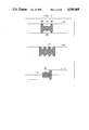
- FIG. 1 shows, in pictorial form, a cross-section of an embodiment of the present invention having a pneumatic drive mechanism
- FIG. 2 shows, in pictorial form, various embodiments of drive-mechanisms for use with embodiments of the present invention
- FIG. 3 shows, in pictorial form, two methods of impact neutralization for use in the embodiments of the present invention
- FIG. 4 shows, in pictorial form, a cross-section of a first embodiment of the present invention having an electromagnetic drive mechanism
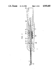
- FIG. 5 shows, in pictorial form, a cross-section of a second embodiment of the present invention having an electromagnetic drive mechanism
- FIG. 6 shows, in pictorial form, a cross-section of a third embodiment of the present invention having an electromagnetic drive mechanism
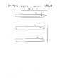
- FIG. 7 shows, in pictorial form, a cross-section of an inner cutting tube for use with embodiments of the present invention
- FIG. 8 shows, in pictorial form, various outer needles having apertures which cooperate with inner tubes of embodiments of the present invention to provide a means for cutting tissue which extends into the aperture in the outer needle;
- FIG. 9 shows, in pictorial form, an infusion sleeve for use with embodiments of the present invention.
- FIG. 10 shows, in pictorial form, an embodiment of a flat spring for use with embodiments of the present invention
- FIG. 11 shows, in pictorial form, an embodiment of an apparatus which provides compressed air pulses for use with embodiments of the present invention
- FIG. 12 shows, in pictorial form, an embodiment of an apparatus for providing compressed air pulses, a vacuum and/or electrical pulses for use with embodiments of the present invention.
- FIG. 13 shows, in pictorial, an embodiment of an apparatus for converting pulses of compressed air into electrical pulses for use with embodiments of the present invention.
- FIG. 1 shows a cross-section of an embodiment of the inventive apparatus, namely, a compressed liquid or gas-powered, intraocular, vitrectomy surgical needle 10.
- Barrel 100 of inventive apparatus 10 is a hollow tube having a substantially circular cross-section.
- the cross-section of the inside of barrel 100 need not be circular and, in fact, may have any one of a number of different shapes such as, for example, a substantially square cross-section.
- Barrel 100 may be fabricated from a sturdy plastic or a metal such as, for example, aluminum, and may have a knurled surface for ease of gripping.
- Plug 110 is press-fit into barrel 100 and comprises cylindrical inner-plug-part 115 and outer-plug-part 116.
- Outer-plug-part 116 may have any one of many shapes and is shown in FIG. 1 to have a hemispherical shaped cross-section.
- Inner-plug-part 115 and outer-plug-part 116 have a passageway axially disposed through the center thereof.
- the passageway through outer-plug-part 116 has two parts, the first, left-hand passageway, as shown in FIG. 1, has a smaller diameter than the second, right-hand passageway. Further, the diameter of the right-hand passageway is substantially the same as the diameter of the passageway in inner-plug-part 115.
- the outer diameter of inner-plug-part 115 is substantially the same as the inner diameter of barrel 100. This ensures that plug 110 will be fixed in position when inner-plug-part 115 is press-fit into barrel 100.
- Plug 120 is press-fit into the other end of barrel 100 from plug 110 and comprises cylindrical plug-part 123, recess-plug-part 127 and rear-portion 129.
- Cylindrical plug-part 123 and recess-plug-part 127 have a passageway axially disposed through the center thereof.
- the outer diameter of cylindrical plug-part 123 is substantially the same as the inner diameter of barrel 100. This ensures that plug 120 will be fixed in position when cylindrical plug-part 123 is press-fit into barrel 100.
- Rear-portion 129 has a relatively large passageway disposed therein and rear-portion 129 merely serves to provide support for a surgeon's hand.
- plugs 115 and 120 may be affixed to barrel 100 by any one of a number of methods other than by being press-fit, for example, plugs 115 and 120 may be glued, wedged, or threadably received into barrel 100.
- Outer needle 130 is inserted into the left-hand passageway in outer-plug-part 116 of plug 110 and is affixed therein by any one of a number of methods such as, for example, by glue inserted into outer-plug-part 116 at position 135 or by being press-fit and so forth.
- Outer needle 130 has a rounded end 145 which is disposed at the other end from its point of insertion into outer-plug-part 116. It should be clear to those of ordinary skill in the art that end 145 may have many different shapes, however, a rounded shape is preferred because it entails less damage to tissues when outer needle 130 is inserted into an eye.
- Aperture 140 is disposed in the sidewall of outer needle 130 near rounded end 145 thereof, but displaced a small distance therefrom towards outer-plug-part 116.
- Outer needle 130 is preferably a hypo-tube which is well-known in the art as a stainless steel tube but may also be fabricated from other materials such as, for example, plastic.
- Drive-mechanism 150 is disposed within barrel 100 and comprises several sections.
- Drive-section 155 of drive 150 comprises a substantially cylindrical body fabricated, for example, from metal or plastic and has a passageway axially disposed through the center thereof. Although drive-section 155 need not be cylindrical, it is preferable that the shape of the cross-section of its outer surface match the shape of the cross-section of the inner surface of barrel 100.
- Indexing-member 165 extends downwardly from the sidewall of barrel 100 and is inserted into groove 160 disposed in drive-section 155.
- Indexing-member 165 may be fabricated, for example, by fabricating a hole in the sidewall of barrel 100, fabricating threads in the hole, and threading a bolt therein which extends through the sidewall of barrel 100 and into indexing-groove 160 of drive-section 155.
- indexing-groove 160 does not extend along the full length of drive-section 155, then end 167 of indexing-groove 160 may act as a stop for drive-mechanism 150. As a result of the above indexing configuration, drive-mechanism 150 does not rotate when it reciprocates within barrel 100.
- Drive-mechanism 150 further comprises drive-section 170 which is disposed adjacent drive-section 155.
- Drive-section 170 has an axially disposed passageway extending therethrough which is substantially colinear with the passageway extending through drive-section 155.
- the cross-section of the outer surface of drive-section 170 may have many different shapes, for example, a circular cross-section.
- the cross-section of the outer surface of drive-section 170 is preferably smaller than the cross-section of the outer surface of drive-section 155.
- Drive-mechanism 150 further comprises drive-section 175 which is disposed adjacent drive-section 170.
- Drive-section 175 has an axially disposed passageway extending therethrough which is substantially colinear with the passageway extending through drive-sections 155 and 170.
- the cross-section of the outer surface of drive-section 175 should conform to the shape and size of the cross-section of the inner surface of barrel 100.
- drive-section 175 is cylindrical and has an outer diameter which is substantially the same as the inner diameter of barrel 100.
- a space is formed between drive-sections 155 and 175 of drive-mechanism 150.
- drive-mechanism 150 While it is not necessary to fabricate drive-mechanism 150 so that this space is formed, i.e., drive-mechanism 150 may be fabricated without utilizing drive-section 170, the embodiment shown in FIG. 1 is a preferred embodiment. This is because the space formed as a result of fabricating drive-section 170 between drive-sections 155 and 175 allows drive-section 175 to flex when drive-mechanism 150 is reciprocated inside barrel 100. Due to this flexing action, the outer surface of drive-section 175 is made to conform to the inner wall of barrel 100 and, as a result, drive-mechanism 150 may advantageously be fabricated without requiring critical tolerances.
- drive-mechanism 150 may advantageously be fabricated without utilizing a sealing apparatus such as an 0-ring for the purpose, as will be explained in detail below, of preventing compressed air from being forced around drive-mechanism 150, into any cf the tubes and, from there, into a patient's eye.
- a sealing apparatus such as an 0-ring for the purpose, as will be explained in detail below, of preventing compressed air from being forced around drive-mechanism 150, into any cf the tubes and, from there, into a patient's eye.
- inventive drive-mechanism 150 is useful for fabricating mechanisms which are powered by compressed liquids or gases such a air-powered cylinders. In such systems, drive-mechanism 150 will serve to be driven by a source of, for example, compressed air. Further embodiments of drive-mechanism 150 are shown in FIG. 2.
- Drive-mechanism 1200 is disposed in cylinder 1201; comprises sections 105, 1206 and 1207; and is adapted to be driven by compressed liquids or compressed gases toward the right and back toward the left. Further, the cross-section of the inside of cylinder 1200 and the outside of sections 1205 and 1207 need not be circular.
- drive-mechanism 1210 is another embodiment thereof.
- embodiment 1240 may serve as a drive-mechanism when it rides on shaft 1250 disposed through the center thereof.
- Shaft 1250 serves to center drive-mechanism 1240 within cylinder 1201. It should be clear to those of ordinary skill in the art that a cross-section of the outside surface of the largest section of drive-mechanism sections 1200, 1210, and 1240 need not be circular but need only conform to the shape of the inside of cylinder 1201. Note, however, if the cross-section of the inner surface of cylinder 1201 is not circular, then indexing will be provided automatically so that a drive-mechanism disposed therein will not rotate.
- Hollow, air-input-tube 180 is affixed to an aperture in the sidewall of barrel 100. Whenever a supply of pressurized fluid or gas, such as air, is affixed to one end of tube 180 (not shown), the liquid or gas is forced into barrel 100 and is forced against drive-section 175 of drive-mechanism 150. This drives drive-mechanism 150 toward the left, as shown in FIG. 1.
- Air-input-tube 180 is affixed to the side wall of barrel 100 by any one of a number of methods known in the art, for example, by gluing at points 190.
- Tube 200 is disposed within barrel 100.
- Tube 200 is cylindrical in shape and has an outer diameter which is smaller than: (1) the inner diameter of the passageway in inner-plug-part 115; (2) the inner diameter of the right-hand passageway in outer-plug-part 116; and (3) the inner diameter of the passageway in plug 120. Further, the outer diameter of tube 200 is substantially the same as the inner diameter of the axially disposed passageway passing through drive-mechanism 150.
- Tube 200 is affixed to drive-mechanism 150 by any one of a number of methods known in the art, for example, by gluing or by being press-fit and so forth.
- FIG. 3 shows two methods for affixing tube 200 to tube 250 and for providing an impact neutralizer for tube 200 within plug 110 as it reciprocates, as will be explained in detail below, within barrel 100.
- tube 250 extends into tube 200 and is affixed in that position by any one of a number of methods known in the art such as, for example, by being press-fit.
- the outer diameter of tube 250 is substantially the same as the inner diameter of tube 200.
- Impact neutralizer means 210 surrounds tube 250 and has an outer diameter which is: (1) substantially the same as or smaller than the inner diameter of the right-hand passageway of outer-plug-part 116; (2) larger than the inner diameter of the left-hand passageway of outer-plug-part 116; and (3) larger than the inner diameter of tube 200.
- impact neutralizer 210 absorbs energy from tube 200 whenever an end thereof impacts outer-plug-part 116.
- tube 250 extends into impact neutralizer 215 which, in turn, is affixed to tube 250.
- Impact neutralizer 215 is formed from any energy-absorbing material and comprises two sections having a passageway axially disposed through the center thereof, outer-impact-part 217 and inner-impact-part 219.
- outer-impact--part 217 and inner-impact-part 219 are cylindrical and inner-impact-part 219 is affixed to tube 200, by being press-fit thereinto.
- the outer diameter of inner-impact-part 219 is substantially the same as the inner diameter of tube 200 and the inner diameter of outer-impact-part 217 and inner-impact-part 219 are substantially the same as the outer diameter of tube 250.
- outer-impact-part 215 is: (1) substantially the same as or smaller than the inner diameter of the right-hand passageway of outer-plug-part 116; (2) larger than the inner diameter of the left-hand passageway of outer-plug-part 116; and (3) larger than the inner diameter of tube 200.
- Tube 200 is affixed to drive-mechanism 150 by, for example, gluing at point 220 at one end of drive-section 155 and at point 230 at one end of drive-section 175. Tube 200 may also be swaged to tube 250. Tube 200 extends through the end of barrel 100 and through the end of rear plug 120. The outer diameter of tube 200 is smaller than the inner diameter of the passageway disposed in rear plug 120. Thus, when drive mechanism 150 is forced to the left by pressurized air entering barrel 100 through air-input-tube 180, tube 200 is also driven to the left because it is affixed to drive-mechanism 150 in the manner described above. Further, tube 200 is driven within the passageways disposed in plugs 110 and 120 because the outer diameter of tube 200, as described above, is smaller than the inner diameter of the passageways disposed within these two plugs.
- the outer diameter of recess-plug-part 127 of plug 120 is substantially less than the inner diameter of barrel 100 to provide a chamber in barrel 100 into which pressurized air enters from air-intake-tube 180.
- the inner diameter of the passageway in recess-plug-part 127 is larger than the outer diameter of tube 200 which extends therethrough.
- Seal 239, disposed in the passageway in recess-plug-part 127, is formed from a relatively soft material such as, for example, urethane or silicone, to prevent pressurized air that enters barrel 100 from leaking out through plug 120.
- Spring return 240 is disposed along tube 200 between inner-plug-part 115 of plug 110 and drive-section 155 of drive-mechanism 150. As a result, spring 240 is compressed when drive-mechanism 150 is driven to the left when pressurized air enters barrel 100 from air-input-tube 180. When pressurized air ceases to flow through air-input-tube 180 and, thereby, against one side of drive-section 175 of drive-mechanism 150, spring 240 forces drive-mechanism 150 back toward the right, as shown in FIG. 1.
- Impact neutralizer means 210 absorbs energy if drive-mechanism 150 causes tube 200 to impact upon impact neutralizer 210 and outer-plug-part 116 and, thereby, reduces any noise and vibration that occurs therewith.
- Tube 250 for example, hypo-tube in stainless steel or plastic, is substantially cylindrical in shape, has an outer diameter which is smaller than the inner diameter of outer needle 130. Further, as has been described above, tube 250 is affixed to tube 200 by any one of a number of methods such as, for example, by being press-fit, by being push-fit thereinto, or by being swaged together. Because tube 250 is affixed to tube 200, as is evident from FIG. 1, as drive-mechanism 150 is driven to the left by pressurized air which enters barrel 100 from air-input-tube 180, so too is tube 250 driven to the left. Further, when drive-mechanism 150 is driven to the right when spring 240 expands, so too is tube 250 driven to the right. As a result, tube 250 undergoes reciprocating motion along the inside of outer needle 130.
- a means for creating a vacuum is affixed to tube 200 at rear end 260 thereof.
- the means for creating a vacuum is not shown but such means are well-known to those of ordinary skill in the art.
- one end of tube 250 includes cutting edge 270 which is disposed to slide along the surface of the inside wall of outer needle 130.
- tube 250 is disposed so that cutting edge 270 will be carried back and forth across aperture 140 in outer needle 130 when tube 250 is reciprocated therewithin.
- the inventive apparatus shown in FIG. 1 functions as follows.
- a vacuum is applied to rear end 260 of tube 200.
- the vacuum is transmitted through tube 200 to tube 250 and, finally, through tube 250 to aperture 140 in outer needle 130.
- Outer needle 130 is inserted into the vitreous portion of an eye through an incision made in the cornea thereof.
- the vacuum causes vitreous tissue to be drawn into outer needle 130 through aperture 140.
- An operator then causes a source of compressed air to be applied to air-input-tube 180.
- compressed air enters barrel 100 and drives drive-mechanism 150 to the left.
- cutting edge 270 of tube 250 is driven across aperture 140 and, thereby, slices off a bit of the tissue which extends through aperture 140 into outer needle 130.
- the movement of drive-mechanism 150 to the left should extend sufficiently far that cutting edge 270 of tube 250 is driven past the left-most extent of aperture 140. This will ensure proper scissoring action to slice the tissue cleanly off.
- the vacuum applied through rear end 260 of tube 200 then causes this tissue to be drawn through the tubes and into a collecting means, not shown.
- Barrel 100 contains exhaust ports 260 to 263 which vent air that is compressed by the reciprocating motion of drive-mechanism 150 within barrel 100. Exhaust ports 260 to 263 prevent compressed air from: (1) being forced into any of the tubes and, therefrom, into the eye and (2) resisting the motion of drive-mechanism 150 to the left. Still further, exhaust ports 260 to 263 help prevent any build up of heat in apparatus 10.
- FIG. 4 shows a cross-section of another embodiment of the present invention, namely an electromagnetically-powered, intraocular, vitectomy surgical needle 11, which is similar in many respects to apparatus 10 shown in FIG. 1.
- the drive system for the embodiment shown in FIG. 4 comprises an electromagnetic drive system whereas the drive system for the embodiment shown in FIG. 1 is a compressed liquid or gas drive system.
- drive-mechanism 300 comprises bobbin 310 having wires 320 wound therearound and a passageway axially disposed in the center thereof.
- tube 260 is comprised of a substantially non-magnetic material such as, for example, aluminum or plastic, to prevent tube 260 from sticking to bobbin 310 and to improve efficiency.
- Magnetic-structure 330 for example, a steel cylinder, is affixed to the outside of a portion of tube 260 and the outer diameter of magnetic-structure 330 is smaller than the diameter of the passageway disposed within bobbin 310 of drive-mechanism 300. Indexing means (not shown) for magnetic-structure 330 are discussed below.
- Spring 240 is disposed against one end of magnetic-structure 330 and has an outer diameter which is smaller than the outer diameter of magnetic-structure 330. When no current is applied to wires 320 and spring 240 is not compressed, magnetic-structure 330 is disposed so that a portion thereof extends outside of the passageway in bobbin 310 to the right towards rear plug 120.
- Wire 320 is wrapped around bobbin 310 and is extended through aperture 340 in plug 120 to a supply of electric current, which supply is well known in the art and not shown in FlG. 4.
- Impact neutralizer means 335 formed from an energy absorbing material such as, for example, a soft washer, is disposed adjacent rear plug 120 to absorb energy from magnetic-structure 330 if it strikes rear plug 120 when magnetic-structure 330 reciprocates within barrel 100 and impact neutralizer means 210 acts, as was discussed above with respect to the embodiment shown in FIG. 1, to absorb energy if tube 260 strikes front plug 110.
- the inner diameter of impact neutralizer means 335 is larger than the outer diameter of tube 260 but is smaller than the outer diameter of magnetic-structure 330.
- indexing to prevent tube 250 from rotating with respect to outer needle 140 is provided in any one of a number of ways.
- the cross-section of the outer surface of magnetic-structure 330 may be fabricated to have a non-circular shape such as, for example, a hexagon, a square and so forth, and the passageway disposed within bobbin 330 is then fabricated to have the same shape.
- a groove may be disposed within magnetic-structure 330 and a member may be fabricated on bobbin 310 which extends into the groove.
- FIG. 5 shows a cross-section of a further embodiment of the present invention which comprises an electromagnetic drive system.
- Barrel 600 of inventive apparatus 15 is a hollow tube having a substantially circular cross-section.
- the cross-section of the inside of barrel 600 need not be circulur and, in fact, may have any one of a number of different shapes such as, for example, a substantially square or hexagonal cross-section.
- Barrel 600 may be fabricated from a sturdy plastic or a metal such as, for example, aluminum, and may have a knurled surface for ease of gripping.
- barrel 610, a hollow tube, like barrel 600, is affixed to barrel 600 by, for example, being press-fit thereinto, and has a smaller outside diameter than barrel 600.
- barrel 610 is not necessary for operation of the apparatus, it provides a preferred embodiment because barrel 610 substantially improves a surgeon's ability to grip and use the inventive apparatus.
- Barrel 610 has vents 611 and 612 disposed in the sidewall thereof which prevent any compressed air from being forced into outer needle 700 and, from there, into a patient's eye. Further, vents 611 and 612 prevent any heat build-up in apparatus 15.
- Plug 620 is press-fit into barrel 610 and comprises cylindrical inner-plug-part 630 and outer-plug-part 640.
- Outer-plug-part 640 may have any one of man shapes and is shown in FIG. 5 to have a trapezoidally shaped cross-section.
- Inner-plug-part 630 and outer-plug-part 640 have a passageway axially disposed through the center thereof.
- the outer diameter of inner-plug-part 630 is substantially the same as the inner diameter of barrel 610. This ensures that plug 620 will be fixed in position when inner-plug-part 630 is press-fit into barrel 610. It should be clear to those of ordinary skill in the art that further embodiments of the present invention include embodiments wherein plug 620 and barrel 610 are fabricated as a single piece.
- Plug 650 is press-fit into the end of barrel 600 which is opposite from barrel 610 and comprises a cylindrical inner-plug-part 660 and outer-plug-part 670.
- Outer-plug-part 670 may have any one of many shapes and is shown in FIG. 5 to have a triangularly shaped cross-section.
- Inner-plug-part 660 and outer-plug-part 670 have a passageway axially disposed through the center thereof and have several, smaller apertures, for example, 680 and 690, disposed therethrough which serve, as will be explained in further detail below, as vents.
- the outer diameter of inner-plug-part 660 is substantially the same as the inner diameter of barrel 600.
- plug 650 will be fixed in position when plug 650 is press-fit into barrel 600.
- plug 620 may be affixed to barrel 610 and that plug 650 may be affixed to barrel 600 by any one of a number of methods other than by being press-fit, for example, plugs 620 and 650 may also be glued, wedged, or threadably received into barrels 610 and 600, respectively.
- plugs 620 and 650 may also be glued, wedged, or threadably received into barrels 610 and 600, respectively.
- further embodiments of the present invention include embodiments wherein plug 650 and barrel 600 are fabricated as a single piece.
- Outer needle 700 is inserted into plug 620 and is affixed therein by any one of a number of methods such as, for example, by gluing or by being press-fit and so forth. In fact, outer needle 700 may even extend through plug 620 and into the passageway disposed within barrel 610. Outer needle 700 has a rounded end 710 which is disposed at the other end from its point of insertion into plug 620. It should be clear to those of ordinary skill in the art that end 710 may have many different shapes, however, a rounded shape is preferred because it entails less damage to tissues when outer needle 700 is inserted into an eye.
- Aperture 720 is disposed in the sidewall of outer needle 700 near the rounded end thereof, but displaced a small distance therefrom towards plug 620.
- Outer needle 700 is preferably a hypo-tube which is well-known in the art as a stainless steel tube but may also be fabricated from other materials such as, for example, plastic.
- Inner tube 737 is disposed within outer needle 700 and has an outer diameter which is smaller than the inner diameter of outer needle 700.
- Tube 737 has sharp, cutting edge 725 disposed at one end and the other end extends through the passageway in plug 620 and is affixed to tube 800 by any one of a number of methods such as, for example, by being press-fit.
- the outer diameter of tube 737 is substantially the same as the inner diameter of tube 800.
- Drive-mechanism 730 is disposed within barrel 600 and comprises several sections. These sections include bobbin 740 which has a passageway axially disposed in the center thereof and wires 750 wound therearound. Wires 750 extend through aperture 617 in barrel 600 to a supply of electric current, which supply is well known in the art and not shown in FIG. 5.
- Tube 800 extends through the passageway in bobbin 740 and is comprised of a substantially non-magnetic material such as, for example, aluminum, to prevent tube 800 from sticking to bobbin 740.
- Magnetic-structure 760 for example, a steel cylinder or slug of steel, is affixed to the outside of a portion of tube 800.
- the outer diameter of magnetic-structure 760 is smaller than the diameter of the passageway disposed within bobbin 740 of drive-mechanism 730. It should be clear to those of ordinary skill in the art that drive-mechanism 730 typically has a ferrous slug (not shown for clarity) disposed in the front end of bobbin 740. This slug is so disposed that magnetic-structure 760 would be attracted thereto when current is applied to wires 750. Magnetic-structure 760 further comprises pin-member 765 which extends outward from the outer surface thereof.
- Pin-member 765 may be fabricated by any one of a number of methods such as, for example, by drilling and tapping a hole in magnetic-structure 760 and threading a bolt therein, by drilling a hole in magnetic-structure 760 and press-fitting a bolt therein and so forth.
- Magnetic-structure 760 is further affixed to spring-containment-means 799, which spring-containment-means 799 comprises a first cylindrical section 795 and a second cylindrical section 790.
- First and second cylindrical sections 790 and 795 have a passageway disposed axially through the center thereof and the diameter of the outer surface of a cross-section of cylindrical section 790 is larger than that of cylindrical section 795 so that a ledge is formed therebetween.
- Indexing means 770 comprises first and second cylindrical sections 780 and 785 and is affixed to bobbin 740.
- First and second cylindrical sections 780 and 785 have a passageway disposed axially through the center thereof whose diameter is greater than the diameter of a cross-section of the outer surface of magnetic-structure 760.
- the diameter of the outer surface of a cross-section of cylindrical section 785 is larger than that of cylindrical section 780 so that a ledge is formed therebetween.
- a groove is disposed along the inner surface of the passageway in cylindrical section 780.
- Pin-member 765 of magnetic-structure 760 is disposed to extend into the groove in the inner surface of the passageway in cylindrical section 780 to provide an indexing means which prevents the rotation of magnetic-structure 760 when it reciprocates within apparatus 15 and, thereby, the rotation of tube 737 relative to outer needle 700.
- indexing to prevent tube 737 from rotating with respect to outer needle 700 may also be provided in any one of a number of other ways.
- the cross-section of the outer surface of magnetic-structure 760 may be fabricated to have a non-circular shape such as, for example, a hexagon, a square and so forth, and the passageway disposed within bobbin 740 is then fabricated to have the same shape.
- Impact neutralizer means 783 is affixed to indexing means 770 and is fabricated from an energy absorbing material such as, for example, urethane, plastic, silicone, and so forth. Impact neutralizer means absorbs energy whenever spring-containment-means 799 impacts thereon.
- Adjusting means 810 is disposed against one side of spring-containment means 799.
- the distance between the end of bobbin 740 and the far end of magnetic-structure 760 is adjustable and is determined by the position of adjusting means 810.
- Adjusting means 810 has a passageway axially disposed through the center thereof and tube 800 extends therethrough.
- adjusting means 810 comprises threaded rod 813 which is threaded into rear plug 650.
- knob 820 affixed to the end of threaded rod 813, has a passageway axially disposed through the center thereof and tube 800 extends therethrough.
- Coiled spring 830 is disposed about magnetic-structure 760, cylindrical section 780 and cylindrical section 795, the outer diameters of cylindrical sections 780 and 795 being substantially the same as the inner diameter of coiled spring 830. In its relaxed position, coiled spring 830 holds spring-containment-means 799 substantially against rod 810.
- a means for creating a vacuum is affixed to tube 800 at the rear end 850 thereof.
- the means for creating a vacuum is not shown but such means are well-known to those of ordinary skill in the art.
- one end of tube 737 includes cutting edge 725 which is disposed to slide along the surface of the inside wall of outer needle 700.
- tube 737 is disposed so that cutting edge 725 will be carried back and forth across aperture 720 in outer needle 700 when tube 737 is reciprocated therewithin.
- inventive apparatus 15 shown in FIG. 5 functions as follows.
- a vacuum is applied to rear end 850 of tube 800.
- the vacuum is transmitted through tube 800 to tube 737 and, finally, through tube 737 to aperture 720 in outer needle 700.
- Outer needle 700 is inserted into the vitreous portion of an eye through an incision made in the cornea thereof.
- the vacuum causes vitreous tissue to be drawn into outer needle 700 through aperture 720.
- An operator then causes a current to be applied to wires 750 and a magnetic field arises in bobbin 740 in response thereto.
- Magnetic-structure 760 is attracted to the left by the magnetic field and moves toward bobbin 740. This movement drives tube 800 to the left and compresses coiled spring 830.
- cutting edge 725 of tube 737 is driven across aperture 720 and, thereby, slices off a bit of the tissue which extends through aperture 720 into outer needle 700.
- the movement of magnetic-structure 760 to the left should extend sufficiently far that cutting edge 725 of tube 737 is driven past the left-most extent of aperture 720. This will ensure proper scissoring action to slice the tissue cleanly off.
- the vacuum applied through rear end 850 of tube 800 then causes this tissue to be drawn through the tubes and into a collecting means, not shown.
- the maximum opening of aperture 720 is determined by adjusting means 810. As adjusting means 810 forces spring-containment-means 799 to the left, the right-most position of cutting edge 725 is forced further to the left. This reduces the maximum opening in aperture 720.
- I can increase the power of the action of the magnetic field emanating from solenoid 730 by wrapping it with more than one wire, for example, two separate wires, and by applying current to each of the wires.
- I have applied current to the wires in parallel by wrapping each end of the two wires together to form two connected ends and then by applying current simultaneously to the two ends.
- spring 830 has been shown to be a coiled spring, many other embodiments may be used such as, for example, a wave washer or a fIat spring and so forth.
- spring 837 is shown in FIG. 10. It should be clear to those of ordinary skill in the art that spring 837 is compressed as plunger 877 moves to the left. It should also be clear that spring 837 will force plunger 877 to the right when the force drawing it to the left is removed.
- coiled spring 830 may be affixed to spring-containment-means 799 but disposed between spring-containment-means 799 and plug 650.
- spring 830 when magnetic-structure 760 is drawn into bobbin 740 as current is applied to wires 750, spring 830 would be compressed. Then, when the current is removed, spring 830 would pull magnetic-structure 760 to the right. It should be clear to those of ordinary skill in the art that many other suitable arrangements may be fabricated utilizing a spring, all of which are within the spirit of the present invention.
- magnetic-structure 760 is affixed to tube 800.
- the cross section of magnetic-structure 760 is larger than the inner diameter of the passageway through bobbin 740.
- Soft bumper 763 is affixed to one end of magnetic-structure 760 and indexing-washer 767 having a larger cross-section than magnetic-structure 760 is affixed to the other end.
- Indexing-rod 769 is affixed to and extends outward from bobbin 740 through an aperture in indexing-washer 767.
- indexing-washer 767 When the current is removed from wires 750, the magnetic field fades and coiled spring 830 pushes indexing-washer 767 and, thereby, magnetic-structure 760 back towards the right. As magnetic structure 760 reciprocates, indexing-rod 769 prevents rotation and bumper 763 prevents vibration.
- a still further embodiment of the present invention which utilizes an electromagnetic drive system comprises the use of a linear motor.
- FIG. 7 shows a prior art tube 400 which corresponds to tube 250 of FIGs. 1 and 4 and tube 737 of FIG. 5.
- Tube 400 includes end 410 which is sharpened and which can cut material which extends through aperture 140 of outer needle 130 of FIGS. 1 and 4 and aperture 720 of outer needle 700 of FIG. 5.
- section 420 of tube 400 was bent upward along the direction of arrow 425 so that an edge of end 410 can scrape along an inside wall of an outer needle to provide a scissoring action and, thereby, a better cutting edge.
- cracks are created in tube 400 due to metal fatigue.
- Inventive tube 450 advantageously overcomes these deficiencies in the following manner: (1) section 460 is bent up slightly in the direction of arrow 485, for example, by 0.005", to again provide a scissoring effect along the inside of an outer needle; (2) section 460 is tapered so that a larger amount of metal exists at portion 470 of tube 450 than existed in prior art tube 400 in order to prevent fatigue; and (3) edge 480 is rounded to provide a means for releasing fatigue. Further, in order to provide an inexpensive means for fabricating the inventive apparatus, cutting edge 490 of inventive tube 450 is ground in one pass on a surface grinder using a grinding wheel having the shape of the cutting edge.
- FIG. 8 shows two embodiments for fabricating the aperture in the side wall of tube 500 which corresponds to outer needle 130 of FIGS. 1 and 4 and outer needle 700 of FIG. 5.
- first embodiment 500 shown in views 1 and 2
- an ellipse 520 is ground near rounded edge 510.
- a cross-section of ellipse 520 is shown in view 2.
- Top edge 521 is blunt whereas bottom edge 522, which extends to the inner wall of tube 500, is sharp.
- Tube 550 is a further embodiment of an outer needle which has round aperture 550 drilled in the sidewall thereof.
- the aperture in the outer needle used in embodiments of the present invention may be oval, rectangular, diamond-shaped and so forth.
- the aperture can be sharpened, as shown by sharp edge 522 of tube 500, or it can be blunt. Nevertheless, I have determined that a preferred embodiment comprises an ellipsoidally shaped aperture 520.
- FIG. 9 shows, in pictorial form, a cross-section of an infusion sleeve available in the prior art for us with embodiments of the present invention.
- Infusion sleeve 1100 is affixed at one end to outer needle 700 and at the other end to barrel 610.
- Infusion sleeve 1100 may be affixed by any one of a number of methods such as, for example, by gluing or by being slip-fit, so that no fluid leaks out.
- Infusion sleeve may be fabricated from any one of a number of materials such as, for example, metal or plastic, and may be molded, formed and so forth.
- Infusion tube 1110 is affixed at one end to infusion sleeve 1100 and at the other end to a source of liquid such as sterile water, not shown. Further, infusion sleeve contains apertures such as aperture 1120 disposed about infusion sleeve 1100.
- fluids enter the eye from aperture 1120 to equalize the pressure therein. Then the vacuum applied to aperture 720 of outer needle 700 draws tissue and liquid into outer needle 700. As a result, the liquids help equalize the pressure in the eye and help transport cut tissue through the inventive apparatus.
- FIG. 11 shows, in pictorial form, an embodiment of an apparatus which provides compressed air pulses for use with embodiments of the present invention.
- Compressor 2000 inputs air through air-input-port 2010 and outputs compressed air through air-output-port 2020.
- Compressor 2000 may be any one of a number of commercially available apparatus such as, for example, a diaphragm pump, a piston pump, a rotary vane pump and so forth, and is activated by electrical supply 2040 through switch 2030.
- Electrical supply 2040 may be a commonly available 110 volt AC supply.
- Cycle timer 2070 is connected to electrical supply 2040 through switch 2030 and outputs electrical pulses in responsa thereto, the rate of the electrical pulses output by cycle timer 2070 being adjusted by adjusting the setting of potentiometer 2060.
- the electrical pulses output by cycle timer 2070 are applied as input to 3-way air-solenoid valve 2110. Further, the output of electrical pulses from cycle timer 2070 is controlled by relay 2090 which is connected to cycle timer 2070 and to 3-way air-solenoid 2110.
- Relay 2090 is controlled, in turn, by foot pedal switch 2100, for example, a 5 volt DC switch. As a result, electrical pulses are applied to air-solenoid valve 2110 whenever foot pedal switch 2100 is depressed.
- 3-way air-solenoid valve 2110 In response to electrical pulses applied to 3-way air-solenoid valve 2110 from cycle timer 2070 and the compressed air applied thereto from compressor 2000, 3-way air-solenoid valve 2110 outputs pulses of compressed air through outlet 2140 and allows air to be vented through air-release vent 2130 between pulses.
- a surgeon connects air-intake-tube 180 from the embodiment shown in FIG. 1 to outlet 2140. Then, switch 2030 is turned on, potentiometer 2060 is set to the value which provides a desired pulse rate and foot pedal switch 2100 is depressed to provide pulses of compressed air for use with the inventive apparatus. It should be well known to those of ordinary skill in the art that many different models of appropriate cycle timers, 3-way air-solenoid valves, relays, and foot pedal switches are commercially available for use in fabricating the apparatus shown in FIG. 11.
- FIG. 12 shows, in pictorial form, an embodiment of an apparatus for providing compressed air pulses, a vacuum and/or electrical pulses for use with embodiments of the present invention.
- the embodiment shown in FIG. 12 includes the apparatus shown in FIG. 11 and contains several additional components.
- FIG. 12 includes vacuum pump 2150 which has vacuum outlet 2160 and vent 2170.
- Vacuum pump 2150 is supplied with electrical voltage and current from electrical supply 2040 which is connected to vacuum pump 2150 through switch 2030.
- a supply of electrical pulses for use with the embodiments shown in FIGS. 4-6 is provided by converting the 110 AC voltage available from electrical supply 2040 to a lower value, for example, 14 volts by transformer 2180.
- the output from transformer 2180 is converted to DC by rectifier 2190 and, in turn, is converted to DC pulses by pulse module 2200 at a rate which is determined by cycle timer 2070.
- the electrical pulses are output from pulse module 2200 at jack 2210.
- the particular arrangement of the components of the apparatus shown in FIG. 12 may advantageously be such as to take advantage of commercially available modules.
- I have modified a vacuum pump module available from Site Microsurgical Systems Inc. ("Site") and added compressor 2000 and 3-way air-solenoid valve 2110 thereto. Then I provided a connection between outlet 2140 of 3-way air-solenoid valve 2110 and an existing Site electrical power module which powers a Site vitrectomy apparatus. Lastly, I added all the remaining components shown in FIG. 12 thereto.
- the existing Site electrical power module can supply air power to my inventive air-powered apparatus and electrical power either to Site's module or to my inventive electromagnetically-powered apparatus.
- FIG. 13 shows, in pictorial, an embodiment of an apparatus for converting pulses of compressed air which may be used, for example, to power the inventive apparatus shown in FIG. 1, into electrical pulses to power the inventive apparatus shown in FIGS. 4-6.
- Jack 3000 is affixed to chamber 3050 and is connected to a source of pulses of compressed air.
- the pulses of compressed air input to jack 3000 are applied to pressure switch 3010 disposed in chamber 3050.
- Jack 3020 is connected to a standard source of electrical voltage, for example, 110 volts AC, and applies this voltage to 12 volt power supply 3030.
- the output from pressure switch 3010 is also applied to power supply 3030.
- power supply 3030 produces 12 volt DC pulses which are applied to output jack 3040 disposed in chamber 3050. These pulses are then used to drive the inventive apparatus shown in FIGS. 4-6.
- Power supply 3030 could be any input or output voltage.
Landscapes
- Health & Medical Sciences (AREA)
- Ophthalmology & Optometry (AREA)
- Heart & Thoracic Surgery (AREA)
- Surgery (AREA)
- Engineering & Computer Science (AREA)
- Biomedical Technology (AREA)
- Nuclear Medicine, Radiotherapy & Molecular Imaging (AREA)
- Vascular Medicine (AREA)
- Life Sciences & Earth Sciences (AREA)
- Animal Behavior & Ethology (AREA)
- General Health & Medical Sciences (AREA)
- Public Health (AREA)
- Veterinary Medicine (AREA)
- Surgical Instruments (AREA)
Abstract
Description
Claims (8)
Priority Applications (1)
| Application Number | Priority Date | Filing Date | Title |
|---|---|---|---|
| US07/143,652 US4940468A (en) | 1988-01-13 | 1988-01-13 | Apparatus for microsurgery |
Applications Claiming Priority (1)
| Application Number | Priority Date | Filing Date | Title |
|---|---|---|---|
| US07/143,652 US4940468A (en) | 1988-01-13 | 1988-01-13 | Apparatus for microsurgery |
Publications (1)
| Publication Number | Publication Date |
|---|---|
| US4940468A true US4940468A (en) | 1990-07-10 |
Family
ID=22504994
Family Applications (1)
| Application Number | Title | Priority Date | Filing Date |
|---|---|---|---|
| US07/143,652 Expired - Fee Related US4940468A (en) | 1988-01-13 | 1988-01-13 | Apparatus for microsurgery |
Country Status (1)
| Country | Link |
|---|---|
| US (1) | US4940468A (en) |
Cited By (160)
| Publication number | Priority date | Publication date | Assignee | Title |
|---|---|---|---|---|
| WO1991002499A1 (en) * | 1989-08-14 | 1991-03-07 | Central Institute For The Deaf | Surgical instrument and cell isolation and transplantation |
| US5047008A (en) * | 1989-10-27 | 1991-09-10 | Storz Instrument Company | Vitrectomy probe |
| US5162044A (en) * | 1990-12-10 | 1992-11-10 | Storz Instrument Company | Phacoemulsification transducer with rotatable handle |
| WO1992021301A1 (en) * | 1991-06-07 | 1992-12-10 | Hemostatix Corporation | Hemostatic bi-polar electrosurgical cutting apparatus and method |
| US5344395A (en) * | 1989-11-13 | 1994-09-06 | Scimed Life Systems, Inc. | Apparatus for intravascular cavitation or delivery of low frequency mechanical energy |
| US5348535A (en) * | 1990-12-14 | 1994-09-20 | Rocin Laboratories, Inc. | Power-assisted liposuction instrument and cannula assembly therefor |
| US5423838A (en) * | 1989-11-13 | 1995-06-13 | Scimed Life Systems, Inc. | Atherectomy catheter and related components |
| US5484436A (en) * | 1991-06-07 | 1996-01-16 | Hemostatic Surgery Corporation | Bi-polar electrosurgical instruments and methods of making |
| US5643198A (en) * | 1990-12-14 | 1997-07-01 | Rocin Laboratories, Inc. | Power-assisted liposuction instrument and cannula assembly therefor |
| US5766166A (en) * | 1995-03-07 | 1998-06-16 | Enable Medical Corporation | Bipolar Electrosurgical scissors |
| US5792165A (en) * | 1993-07-21 | 1998-08-11 | Charles H. Klieman | Endoscopic instrument with detachable end effector |
| US5817119A (en) * | 1993-07-21 | 1998-10-06 | Charles H. Klieman | Surgical instrument for endoscopic and general surgery |
| US5817075A (en) * | 1989-08-14 | 1998-10-06 | Photogenesis, Inc. | Method for preparation and transplantation of planar implants and surgical instrument therefor |
| US5827323A (en) * | 1993-07-21 | 1998-10-27 | Charles H. Klieman | Surgical instrument for endoscopic and general surgery |
| US5827216A (en) * | 1995-06-07 | 1998-10-27 | Cormedics Corp. | Method and apparatus for accessing the pericardial space |
| US5868728A (en) * | 1995-02-28 | 1999-02-09 | Photogenesis, Inc. | Medical linear actuator for surgical delivery, manipulation, and extraction |
| US5873844A (en) * | 1997-01-22 | 1999-02-23 | Campero; Manuel | Method and apparatus for numbing tissue before inserting a needle |
| US5962027A (en) * | 1989-08-14 | 1999-10-05 | Photogenesis, Inc. | Retinal cell transplant |
| US6013049A (en) * | 1998-10-29 | 2000-01-11 | Allergan Sales, Inc. | Controlled outflow sleeve |
| US6033376A (en) * | 1998-09-30 | 2000-03-07 | Allergan Sales, Inc. | Wound shaper sleeve |
| US6045791A (en) * | 1992-03-06 | 2000-04-04 | Photogenesis, Inc. | Retinal pigment epithelium transplantation |
| US6113569A (en) * | 1995-12-21 | 2000-09-05 | Very Inventive Physicians | Reciprocating liposuction device |
| US6132436A (en) * | 1998-07-17 | 2000-10-17 | Allergan | Self-regulating phaco sleeve to reduce tissue burn |
| US6165136A (en) * | 1998-12-23 | 2000-12-26 | Scimed Life Systems, Inc. | Semi-automatic biopsy device and related method of use |
| US6179837B1 (en) | 1995-03-07 | 2001-01-30 | Enable Medical Corporation | Bipolar electrosurgical scissors |
| WO2001015640A1 (en) * | 1999-08-30 | 2001-03-08 | Alcon Universal Ltd. | Method of operating microsurgical instruments |
| NL1013376C2 (en) * | 1999-10-22 | 2001-04-24 | Dutch Ophthalmic Res Ct B V | Surgical cutting tool. |
| US20020042594A1 (en) * | 1998-03-30 | 2002-04-11 | Paul Lum | Apparatus and method for penetration with shaft having a sensor for sensing penetration depth |
| US6391029B1 (en) | 1995-03-07 | 2002-05-21 | Enable Medical Corporation | Bipolar electrosurgical scissors |
| US6394973B1 (en) | 1990-12-14 | 2002-05-28 | Robert L. Cucin | Power-assisted liposuction instrument with cauterizing cannula assembly |
| US20020072757A1 (en) * | 2000-12-06 | 2002-06-13 | Wilson-Cook Medical Inc. | Ligating band delivery apparatus |
| US6464701B1 (en) | 1995-03-07 | 2002-10-15 | Enable Medical Corporation | Bipolar electrosurgical scissors |
| US20020169392A1 (en) * | 2001-05-01 | 2002-11-14 | Csaba Truckai | Electrosurgical working end and method for obtaining tissue samples for biopsy |
| US20030054023A1 (en) * | 1989-08-14 | 2003-03-20 | Photogenesis, Inc. | Volute subretinal implants |
| US20030069579A1 (en) * | 2001-09-13 | 2003-04-10 | Csaba Truckai | Electrosurgical working end with resistive gradient electrodes |
| US20030073980A1 (en) * | 2001-10-16 | 2003-04-17 | Finlay Russell L. | Simultaneous proportional control of surgical parameters in a microsurgical system |
| US20030144652A1 (en) * | 2001-11-09 | 2003-07-31 | Baker James A. | Electrosurgical instrument |
| US20030171748A1 (en) * | 2001-10-22 | 2003-09-11 | Sciogen Llc | Electrosurgical instrument and method of use |
| US20030199870A1 (en) * | 2001-10-22 | 2003-10-23 | Csaba Truckai | Jaw structure for electrosurgical instrument |
| US20030216747A1 (en) * | 2002-02-14 | 2003-11-20 | Kaplan Henry J. | Subretinal implantation device and surgical cannulas for use therewith |
| US20030216732A1 (en) * | 2002-05-20 | 2003-11-20 | Csaba Truckai | Medical instrument with thermochromic or piezochromic surface indicators |
| US6652522B2 (en) | 1990-12-14 | 2003-11-25 | Robert L. Cucin | Power-assisted tissue aspiration instrument with cauterizing cannula assembly |
| US20040059066A1 (en) * | 2001-01-19 | 2004-03-25 | Hironori Yamamoto | Injections for endoscopy |
| US20040073195A1 (en) * | 1990-12-14 | 2004-04-15 | Cucin Robert L. | Power-assisted tissue-aspiration instrument system employing an electronically-controlled air-flow valve assembly within an external instrument controller |
| US6730106B2 (en) * | 2000-10-20 | 2004-05-04 | Nidek Co., Ltd. | Vitreous surgical apparatus |
| US20040096301A1 (en) * | 2000-01-12 | 2004-05-20 | Storage Technology Corporation | Library service port |
| US6743245B2 (en) | 1999-12-20 | 2004-06-01 | Alcon Universal Ltd. | Asynchronous method of operating microsurgical instruments |
| US20040116979A1 (en) * | 2002-10-01 | 2004-06-17 | Surgrx | Electrosurgical instrument and method of use |
| US6773409B2 (en) | 2001-09-19 | 2004-08-10 | Surgrx Llc | Surgical system for applying ultrasonic energy to tissue |
| US20040199161A1 (en) * | 2003-02-14 | 2004-10-07 | Surgrx, Inc., A Delaware Corporation | Electrosurgical probe and method of use |
| US20040215185A1 (en) * | 2001-10-18 | 2004-10-28 | Csaba Truckai | Electrosurgical working end for cotrolled energy delivery |
| US20050159745A1 (en) * | 2004-01-16 | 2005-07-21 | Surgrx, Inc. | Electrosurgical instrument with replaceable cartridge |
| US20050171535A1 (en) * | 2001-10-22 | 2005-08-04 | Surgrx, Inc. | Electrosurgical instrument and method of use |
| US6929644B2 (en) | 2001-10-22 | 2005-08-16 | Surgrx Inc. | Electrosurgical jaw structure for controlled energy delivery |
| US20050267464A1 (en) * | 2001-10-18 | 2005-12-01 | Surgrx, Inc. | Electrosurgical instrument and method of use |
| US20060000823A1 (en) * | 2003-11-19 | 2006-01-05 | Surgrx, Inc. | Polymer compositions exhibiting a PTC property and methods of fabrication |
| US7011657B2 (en) | 2001-10-22 | 2006-03-14 | Surgrx, Inc. | Jaw structure for electrosurgical instrument and method of use |
| US7041102B2 (en) | 2001-10-22 | 2006-05-09 | Surgrx, Inc. | Electrosurgical working end with replaceable cartridges |
| US7083619B2 (en) | 2001-10-22 | 2006-08-01 | Surgrx, Inc. | Electrosurgical instrument and method of use |
| US20070016186A1 (en) * | 2001-03-15 | 2007-01-18 | Lorusso Frank J | Apparatuses and methods for transcleral cautery and subretinal drainage |
| US20070032808A1 (en) * | 2005-08-03 | 2007-02-08 | Azam Anwar | System and method for addressing total occlusion in a vascular environment |
| US7189233B2 (en) | 2001-10-22 | 2007-03-13 | Surgrx, Inc. | Electrosurgical instrument |
| US20070185514A1 (en) * | 2006-02-06 | 2007-08-09 | Kirchhevel G L | Microsurgical instrument |
| US20070185512A1 (en) * | 2006-02-06 | 2007-08-09 | Kirchhevel G L | Microsurgical instrument |
| US20080154292A1 (en) * | 2006-12-22 | 2008-06-26 | Huculak John C | Method of operating a microsurgical instrument |
| US20080172077A1 (en) * | 2006-10-31 | 2008-07-17 | Salomon Valencia | Modular design for ophthalmic surgical probe |
| US20080188881A1 (en) * | 2007-02-02 | 2008-08-07 | James Chon | Dual Coil Vitrectomy Probe |
| US20080208233A1 (en) * | 2006-12-21 | 2008-08-28 | Aaron Barnes | Disposable vitrectomy handpiece |
| US20090088784A1 (en) * | 2007-09-27 | 2009-04-02 | Doheny Eye Institute | Selectable stroke cutter |
| US7600405B2 (en) | 2005-10-11 | 2009-10-13 | Alcon, Inc. | Microsurgical probe |
| US20090312605A1 (en) * | 2004-02-12 | 2009-12-17 | Hallbeck M Susan | Ergonomic handle and articulating laparoscopic tool |
| WO2010118172A1 (en) * | 2009-04-07 | 2010-10-14 | Doheny Eye Institute | Disposable handheld phacomorcellation device |
| US20100312169A1 (en) * | 2009-06-03 | 2010-12-09 | Auld Jack R | Method of operating a vitrectomy probe |
| US7875047B2 (en) | 2002-04-19 | 2011-01-25 | Pelikan Technologies, Inc. | Method and apparatus for a multi-use body fluid sampling device with sterility barrier release |
| US7892183B2 (en) | 2002-04-19 | 2011-02-22 | Pelikan Technologies, Inc. | Method and apparatus for body fluid sampling and analyte sensing |
| US7901365B2 (en) | 2002-04-19 | 2011-03-08 | Pelikan Technologies, Inc. | Method and apparatus for penetrating tissue |
| US7905897B2 (en) | 2001-03-14 | 2011-03-15 | Tyco Healthcare Group Lp | Trocar device |
| US7909774B2 (en) | 2002-04-19 | 2011-03-22 | Pelikan Technologies, Inc. | Method and apparatus for penetrating tissue |
| US7909775B2 (en) | 2001-06-12 | 2011-03-22 | Pelikan Technologies, Inc. | Method and apparatus for lancet launching device integrated onto a blood-sampling cartridge |
| US7909777B2 (en) | 2002-04-19 | 2011-03-22 | Pelikan Technologies, Inc | Method and apparatus for penetrating tissue |
| US7909778B2 (en) | 2002-04-19 | 2011-03-22 | Pelikan Technologies, Inc. | Method and apparatus for penetrating tissue |
| US7914465B2 (en) | 2002-04-19 | 2011-03-29 | Pelikan Technologies, Inc. | Method and apparatus for penetrating tissue |
| US7955331B2 (en) | 2004-03-12 | 2011-06-07 | Ethicon Endo-Surgery, Inc. | Electrosurgical instrument and method of use |
| US20110144681A1 (en) * | 2001-03-14 | 2011-06-16 | Tyco Healthcare Group Lp | Trocar device |
| US7976476B2 (en) | 2002-04-19 | 2011-07-12 | Pelikan Technologies, Inc. | Device and method for variable speed lancet |
| US7981055B2 (en) | 2001-06-12 | 2011-07-19 | Pelikan Technologies, Inc. | Tissue penetration device |
| US7981056B2 (en) | 2002-04-19 | 2011-07-19 | Pelikan Technologies, Inc. | Methods and apparatus for lancet actuation |
| US7988645B2 (en) | 2001-06-12 | 2011-08-02 | Pelikan Technologies, Inc. | Self optimizing lancing device with adaptation means to temporal variations in cutaneous properties |
| US8007446B2 (en) | 2002-04-19 | 2011-08-30 | Pelikan Technologies, Inc. | Method and apparatus for penetrating tissue |
| US8025199B2 (en) | 2004-02-23 | 2011-09-27 | Tyco Healthcare Group Lp | Surgical cutting and stapling device |
| US8062231B2 (en) | 2002-04-19 | 2011-11-22 | Pelikan Technologies, Inc. | Method and apparatus for penetrating tissue |
| US8075558B2 (en) | 2002-04-30 | 2011-12-13 | Surgrx, Inc. | Electrosurgical instrument and method |
| US8079960B2 (en) | 2002-04-19 | 2011-12-20 | Pelikan Technologies, Inc. | Methods and apparatus for lancet actuation |
| US8197421B2 (en) | 2002-04-19 | 2012-06-12 | Pelikan Technologies, Inc. | Method and apparatus for penetrating tissue |
| US20120158006A1 (en) * | 2010-12-15 | 2012-06-21 | Mcdonell Brian William | Reduced Friction Vitrectomy Probe |
| US8221334B2 (en) | 2002-04-19 | 2012-07-17 | Sanofi-Aventis Deutschland Gmbh | Method and apparatus for penetrating tissue |
| US8251921B2 (en) | 2003-06-06 | 2012-08-28 | Sanofi-Aventis Deutschland Gmbh | Method and apparatus for body fluid sampling and analyte sensing |
| US8262614B2 (en) | 2003-05-30 | 2012-09-11 | Pelikan Technologies, Inc. | Method and apparatus for fluid injection |
| US8267870B2 (en) | 2002-04-19 | 2012-09-18 | Sanofi-Aventis Deutschland Gmbh | Method and apparatus for body fluid sampling with hybrid actuation |
| US8277418B2 (en) | 2009-12-23 | 2012-10-02 | Alcon Research, Ltd. | Ophthalmic valved trocar cannula |
| US8282576B2 (en) | 2003-09-29 | 2012-10-09 | Sanofi-Aventis Deutschland Gmbh | Method and apparatus for an improved sample capture device |
| US8298253B2 (en) | 2010-05-27 | 2012-10-30 | Alcon Research, Ltd. | Variable drive vitrectomy cutter |
| US8296918B2 (en) | 2003-12-31 | 2012-10-30 | Sanofi-Aventis Deutschland Gmbh | Method of manufacturing a fluid sampling device with improved analyte detecting member configuration |
| US8333710B2 (en) | 2002-04-19 | 2012-12-18 | Sanofi-Aventis Deutschland Gmbh | Tissue penetration device |
| US8343106B2 (en) | 2009-12-23 | 2013-01-01 | Alcon Research, Ltd. | Ophthalmic valved trocar vent |
| US8360992B2 (en) | 2002-04-19 | 2013-01-29 | Sanofi-Aventis Deutschland Gmbh | Method and apparatus for penetrating tissue |
| US8372016B2 (en) | 2002-04-19 | 2013-02-12 | Sanofi-Aventis Deutschland Gmbh | Method and apparatus for body fluid sampling and analyte sensing |
| US8382682B2 (en) | 2002-04-19 | 2013-02-26 | Sanofi-Aventis Deutschland Gmbh | Method and apparatus for penetrating tissue |
| US8435190B2 (en) | 2002-04-19 | 2013-05-07 | Sanofi-Aventis Deutschland Gmbh | Method and apparatus for penetrating tissue |
| US8465471B2 (en) | 2009-08-05 | 2013-06-18 | Rocin Laboratories, Inc. | Endoscopically-guided electro-cauterizing power-assisted fat aspiration system for aspirating visceral fat tissue within the abdomen of a patient |
| US20130158584A1 (en) * | 2011-12-20 | 2013-06-20 | John R. Underwood | Vitrectomy probe with adjustable cutter port size |
| US8556829B2 (en) | 2002-04-19 | 2013-10-15 | Sanofi-Aventis Deutschland Gmbh | Method and apparatus for penetrating tissue |
| US8574895B2 (en) | 2002-12-30 | 2013-11-05 | Sanofi-Aventis Deutschland Gmbh | Method and apparatus using optical techniques to measure analyte levels |
| US8641644B2 (en) | 2000-11-21 | 2014-02-04 | Sanofi-Aventis Deutschland Gmbh | Blood testing apparatus having a rotatable cartridge with multiple lancing elements and testing means |
| US8652831B2 (en) | 2004-12-30 | 2014-02-18 | Sanofi-Aventis Deutschland Gmbh | Method and apparatus for analyte measurement test time |
| US8668656B2 (en) | 2003-12-31 | 2014-03-11 | Sanofi-Aventis Deutschland Gmbh | Method and apparatus for improving fluidic flow and sample capture |
| US8702624B2 (en) | 2006-09-29 | 2014-04-22 | Sanofi-Aventis Deutschland Gmbh | Analyte measurement device with a single shot actuator |
| US8721671B2 (en) | 2001-06-12 | 2014-05-13 | Sanofi-Aventis Deutschland Gmbh | Electric lancet actuator |
| US8784335B2 (en) | 2002-04-19 | 2014-07-22 | Sanofi-Aventis Deutschland Gmbh | Body fluid sampling device with a capacitive sensor |
| US8828203B2 (en) | 2004-05-20 | 2014-09-09 | Sanofi-Aventis Deutschland Gmbh | Printable hydrogels for biosensors |
| US8845666B2 (en) | 2010-12-21 | 2014-09-30 | Alcon Research, Ltd. | Vitrectomy probe with adjustable cutter port size |
| US8965476B2 (en) | 2010-04-16 | 2015-02-24 | Sanofi-Aventis Deutschland Gmbh | Tissue penetration device |
| US9101441B2 (en) | 2010-12-21 | 2015-08-11 | Alcon Research, Ltd. | Vitrectomy probe with adjustable cutter port size |
| US20150223979A1 (en) * | 2012-08-28 | 2015-08-13 | Mani, Inc. | Vitreous body surgical probe and method of manufacturing same |
| US9144401B2 (en) | 2003-06-11 | 2015-09-29 | Sanofi-Aventis Deutschland Gmbh | Low pain penetrating member |
| US9226699B2 (en) | 2002-04-19 | 2016-01-05 | Sanofi-Aventis Deutschland Gmbh | Body fluid sampling module with a continuous compression tissue interface surface |
| US9248267B2 (en) | 2002-04-19 | 2016-02-02 | Sanofi-Aventis Deustchland Gmbh | Tissue penetration device |
| US9314194B2 (en) | 2002-04-19 | 2016-04-19 | Sanofi-Aventis Deutschland Gmbh | Tissue penetration device |
| US9351680B2 (en) | 2003-10-14 | 2016-05-31 | Sanofi-Aventis Deutschland Gmbh | Method and apparatus for a variable user interface |
| US9375169B2 (en) | 2009-01-30 | 2016-06-28 | Sanofi-Aventis Deutschland Gmbh | Cam drive for managing disposable penetrating member actions with a single motor and motor and control system |
| US9386944B2 (en) | 2008-04-11 | 2016-07-12 | Sanofi-Aventis Deutschland Gmbh | Method and apparatus for analyte detecting device |
| US9427532B2 (en) | 2001-06-12 | 2016-08-30 | Sanofi-Aventis Deutschland Gmbh | Tissue penetration device |
| US9486360B2 (en) | 2013-12-05 | 2016-11-08 | Novartis Ag | Dual electromagnetic coil vitrectomy probe |
| WO2016178178A1 (en) * | 2015-05-07 | 2016-11-10 | Novartis Ag | Ophthalmic surgical device handle and associated devices, systems, and methods |
| US9498378B2 (en) | 2014-04-04 | 2016-11-22 | Novartis Ag | Minimal pulsation ophthalmic probe |
| US9615969B2 (en) | 2012-12-18 | 2017-04-11 | Novartis Ag | Multi-port vitrectomy probe with dual cutting edges |
| US9693898B2 (en) | 2014-11-19 | 2017-07-04 | Novartis Ag | Double-acting vitreous probe with contoured port |
| US9775553B2 (en) | 2004-06-03 | 2017-10-03 | Sanofi-Aventis Deutschland Gmbh | Method and apparatus for a fluid sampling device |
| US9795747B2 (en) | 2010-06-02 | 2017-10-24 | Sanofi-Aventis Deutschland Gmbh | Methods and apparatus for lancet actuation |
| US9820684B2 (en) | 2004-06-03 | 2017-11-21 | Sanofi-Aventis Deutschland Gmbh | Method and apparatus for a fluid sampling device |
| US9925314B2 (en) | 2009-08-05 | 2018-03-27 | Rocin Laboratories, Inc. | Method of performing intra-abdominal tissue aspiration to ameliorate the metabolic syndrome, or abdominal obesity |
| US10070990B2 (en) | 2011-12-08 | 2018-09-11 | Alcon Research, Ltd. | Optimized pneumatic drive lines |
| US20190099292A1 (en) * | 2017-10-04 | 2019-04-04 | Abbott Medical Optics Inc. | Electronic guillotine vitrectomy cutter |
| US10251782B2 (en) | 2014-10-29 | 2019-04-09 | Novartis Ag | Vitrectomy probe with a counterbalanced electromagnetic drive |
| US10543122B2 (en) | 2016-12-19 | 2020-01-28 | New World Medical, Inc. | Ocular treatment devices and related methods of use |
| WO2020081419A1 (en) * | 2018-10-17 | 2020-04-23 | Gyrus Acmi, Inc. | Medical device |
| US10709431B2 (en) | 2017-06-14 | 2020-07-14 | Epic Medical Concepts & Innovations, Inc. | Laparoscopic devices and related methods |
| EP3698737A1 (en) * | 2019-02-22 | 2020-08-26 | Gyrus ACMI, Inc. D.B.A. Olympus Surgical Technologies America | Reciprocating surgical shaver |
| EP3714816A1 (en) * | 2019-03-27 | 2020-09-30 | Gyrus ACMI, Inc. D.B.A. Olympus Surgical Technologies America | Planar alignment for asymmetric cutting members |
| WO2020237049A1 (en) | 2019-05-21 | 2020-11-26 | The Regents Of The University Of Michigan | Devices, systems, and methods for biological sample collection |
| US10874552B2 (en) | 2011-07-08 | 2020-12-29 | Doheny Eye Institute | Ocular lens cutting device |
| WO2021021800A1 (en) | 2019-07-29 | 2021-02-04 | Bionaut Labs Ltd. | Devices for safe and reliable access to sub arachnoid and subdural space |
| US11141182B2 (en) | 2019-03-01 | 2021-10-12 | Gyrus Acmi, Inc. | Methods of reciprocation in a surgical shaver |
| US11147579B2 (en) | 2019-02-27 | 2021-10-19 | Gyrus Acmi. Inc. | Methods of reciprocation in a surgical shaver |
| US11213312B2 (en) | 2019-02-27 | 2022-01-04 | Gyrus Acmi, Inc. | Methods of reciprocation in a surgical shaver |
| US20220160544A1 (en) * | 2020-11-20 | 2022-05-26 | Alcon Inc. | Fluid driven vitrectomy probe |
| US20220175381A1 (en) * | 2009-02-05 | 2022-06-09 | Cilag Gmbh International | Surgical stapling instrument comprising a magnetic element driver |
| CN114949391A (en) * | 2022-05-24 | 2022-08-30 | 四川大学华西医院 | Device for removing retention in alimentary canal |
| US11517341B2 (en) | 2019-02-22 | 2022-12-06 | Gyrus ACMl, Inc. | Methods of reciprocation in a surgical shaver |
| US11564705B2 (en) * | 2018-01-26 | 2023-01-31 | Gyras ACMI, Inc. | Disposable debrider with cannulated solenoid |
Citations (15)
| Publication number | Priority date | Publication date | Assignee | Title |
|---|---|---|---|---|
| US1677209A (en) * | 1926-04-21 | 1928-07-17 | Joseph H Zumbalen | Surgical instrument |
| US2703557A (en) * | 1951-02-05 | 1955-03-08 | Polki Samuel | Pneumatic hand tool |
| US3173414A (en) * | 1961-10-23 | 1965-03-16 | Levallois Optique Et Prec | Biopsy probe, and combination thereof with an endoscope |
| US3180236A (en) * | 1962-12-20 | 1965-04-27 | Beckett Harcum Co | Fluid motor construction |
| US3614953A (en) * | 1968-01-30 | 1971-10-26 | Nat Res Dev | Drills for clearing obstructions in arteries |
| US3776238A (en) * | 1971-08-24 | 1973-12-04 | Univ California | Ophthalmic instrument |
| US3815604A (en) * | 1972-06-19 | 1974-06-11 | Malley C O | Apparatus for intraocular surgery |
| US3828791A (en) * | 1973-03-21 | 1974-08-13 | M Santos | Surgical instruments |
| US3884238A (en) * | 1972-06-19 | 1975-05-20 | Malley Conor C O | Apparatus for intraocular surgery |
| US3994297A (en) * | 1974-12-09 | 1976-11-30 | Kopf J David | Ophthalmic instrument |
| US4009654A (en) * | 1974-12-20 | 1977-03-01 | General Electric Company | Automatic modification of the print control in a printing device |
| US4011869A (en) * | 1975-08-01 | 1977-03-15 | David Kopf Instruments | Tubular cutting instrument |
| US4214507A (en) * | 1977-08-24 | 1980-07-29 | Vries Donald S Jr De | One-piece plastic piston |
| US4577629A (en) * | 1983-10-28 | 1986-03-25 | Coopervision, Inc. | Surgical cutting instrument for ophthalmic surgery |
| US4650460A (en) * | 1984-06-28 | 1987-03-17 | Jaime Roizenblatt | Pneumatic module for intraocular microsurgery |
-
1988
- 1988-01-13 US US07/143,652 patent/US4940468A/en not_active Expired - Fee Related
Patent Citations (15)
| Publication number | Priority date | Publication date | Assignee | Title |
|---|---|---|---|---|
| US1677209A (en) * | 1926-04-21 | 1928-07-17 | Joseph H Zumbalen | Surgical instrument |
| US2703557A (en) * | 1951-02-05 | 1955-03-08 | Polki Samuel | Pneumatic hand tool |
| US3173414A (en) * | 1961-10-23 | 1965-03-16 | Levallois Optique Et Prec | Biopsy probe, and combination thereof with an endoscope |
| US3180236A (en) * | 1962-12-20 | 1965-04-27 | Beckett Harcum Co | Fluid motor construction |
| US3614953A (en) * | 1968-01-30 | 1971-10-26 | Nat Res Dev | Drills for clearing obstructions in arteries |
| US3776238A (en) * | 1971-08-24 | 1973-12-04 | Univ California | Ophthalmic instrument |
| US3815604A (en) * | 1972-06-19 | 1974-06-11 | Malley C O | Apparatus for intraocular surgery |
| US3884238A (en) * | 1972-06-19 | 1975-05-20 | Malley Conor C O | Apparatus for intraocular surgery |
| US3828791A (en) * | 1973-03-21 | 1974-08-13 | M Santos | Surgical instruments |
| US3994297A (en) * | 1974-12-09 | 1976-11-30 | Kopf J David | Ophthalmic instrument |
| US4009654A (en) * | 1974-12-20 | 1977-03-01 | General Electric Company | Automatic modification of the print control in a printing device |
| US4011869A (en) * | 1975-08-01 | 1977-03-15 | David Kopf Instruments | Tubular cutting instrument |
| US4214507A (en) * | 1977-08-24 | 1980-07-29 | Vries Donald S Jr De | One-piece plastic piston |
| US4577629A (en) * | 1983-10-28 | 1986-03-25 | Coopervision, Inc. | Surgical cutting instrument for ophthalmic surgery |
| US4650460A (en) * | 1984-06-28 | 1987-03-17 | Jaime Roizenblatt | Pneumatic module for intraocular microsurgery |
Cited By (318)
| Publication number | Priority date | Publication date | Assignee | Title |
|---|---|---|---|---|
| US20030054023A1 (en) * | 1989-08-14 | 2003-03-20 | Photogenesis, Inc. | Volute subretinal implants |
| US6579256B2 (en) | 1989-08-14 | 2003-06-17 | Photogenesis, Inc. | Instrument for subretinal implantation |
| WO1991002499A1 (en) * | 1989-08-14 | 1991-03-07 | Central Institute For The Deaf | Surgical instrument and cell isolation and transplantation |
| US5962027A (en) * | 1989-08-14 | 1999-10-05 | Photogenesis, Inc. | Retinal cell transplant |
| US20060039993A1 (en) * | 1989-08-14 | 2006-02-23 | Hughes Stephen E | Retinal cell grafts and instrument for implanting |
| US5817075A (en) * | 1989-08-14 | 1998-10-06 | Photogenesis, Inc. | Method for preparation and transplantation of planar implants and surgical instrument therefor |
| US6955809B2 (en) | 1989-08-14 | 2005-10-18 | Photogenesis, Inc. | Retinal cell grafts |
| US5047008A (en) * | 1989-10-27 | 1991-09-10 | Storz Instrument Company | Vitrectomy probe |
| US5344395A (en) * | 1989-11-13 | 1994-09-06 | Scimed Life Systems, Inc. | Apparatus for intravascular cavitation or delivery of low frequency mechanical energy |
| US5423838A (en) * | 1989-11-13 | 1995-06-13 | Scimed Life Systems, Inc. | Atherectomy catheter and related components |
| US5162044A (en) * | 1990-12-10 | 1992-11-10 | Storz Instrument Company | Phacoemulsification transducer with rotatable handle |
| US5348535A (en) * | 1990-12-14 | 1994-09-20 | Rocin Laboratories, Inc. | Power-assisted liposuction instrument and cannula assembly therefor |
| US6761701B2 (en) | 1990-12-14 | 2004-07-13 | Robert L. Cucin | Power-assisted liposuction instrument with cauterizing cannula assembly |
| US20050197648A1 (en) * | 1990-12-14 | 2005-09-08 | Cucin Robert L. | Power-assisted liposuction instrument with cauterizing cannula assembly |
| US5643198A (en) * | 1990-12-14 | 1997-07-01 | Rocin Laboratories, Inc. | Power-assisted liposuction instrument and cannula assembly therefor |
| US20050256445A1 (en) * | 1990-12-14 | 2005-11-17 | Cucin Robert L | Controller for use with an air-powered tissue-aspiration instrument system |
| US6394973B1 (en) | 1990-12-14 | 2002-05-28 | Robert L. Cucin | Power-assisted liposuction instrument with cauterizing cannula assembly |
| US20040167516A1 (en) * | 1990-12-14 | 2004-08-26 | Cucin Robert L. | Electro-cauterizing cannula assembly for use with power-assisted liposuction instruments |
| US6652522B2 (en) | 1990-12-14 | 2003-11-25 | Robert L. Cucin | Power-assisted tissue aspiration instrument with cauterizing cannula assembly |
| US7112200B2 (en) | 1990-12-14 | 2006-09-26 | Cucin Robert L | Electro-cauterizing cannula assembly for use with power-assisted liposuction instruments |
| US20070123850A1 (en) * | 1990-12-14 | 2007-05-31 | Cucin Robert L | Power-assisted liposuction instrument with cauterizing cannula assembly |
| US7381206B2 (en) | 1990-12-14 | 2008-06-03 | Cucin Robert L | Power-assisted tissue-aspiration instrument system employing an electronically-controlled air-flow valve assembly within an external instrument controller |
| US20090076486A1 (en) * | 1990-12-14 | 2009-03-19 | Cucin Robert L | Multi-core connector system for interfacing first and second subsystems supporting air and electrical lines |
| US20040073195A1 (en) * | 1990-12-14 | 2004-04-15 | Cucin Robert L. | Power-assisted tissue-aspiration instrument system employing an electronically-controlled air-flow valve assembly within an external instrument controller |
| US7740605B2 (en) | 1990-12-14 | 2010-06-22 | Cucin Robert L | Power-assisted liposuction instrument with cauterizing cannula assembly |
| US7384417B2 (en) | 1990-12-14 | 2008-06-10 | Cucin Robert L | Air-powered tissue-aspiration instrument system employing curved bipolar-type electro-cauterizing dual cannula assembly |
| US5769849A (en) * | 1991-06-07 | 1998-06-23 | Hemostatic Surgery Corporation | Bi-polar electrosurgical endoscopic instruments |
| WO1992021301A1 (en) * | 1991-06-07 | 1992-12-10 | Hemostatix Corporation | Hemostatic bi-polar electrosurgical cutting apparatus and method |
| US5324289A (en) * | 1991-06-07 | 1994-06-28 | Hemostatic Surgery Corporation | Hemostatic bi-polar electrosurgical cutting apparatus and methods of use |
| US5484436A (en) * | 1991-06-07 | 1996-01-16 | Hemostatic Surgery Corporation | Bi-polar electrosurgical instruments and methods of making |
| AU672753B2 (en) * | 1991-06-07 | 1996-10-17 | Vital Medical Products Corporation | Hemostatic bi-polar electrosurgical cutting apparatus and method |
| US5776128A (en) * | 1991-06-07 | 1998-07-07 | Hemostatic Surgery Corporation | Hemostatic bi-polar electrosurgical cutting apparatus |
| US5810808A (en) * | 1991-06-07 | 1998-09-22 | Hemostatic Surgery Corporation | Hemostatic bi-polar electrosurgical cutting apparatus and methods of use |
| US6045791A (en) * | 1992-03-06 | 2000-04-04 | Photogenesis, Inc. | Retinal pigment epithelium transplantation |
| US5817119A (en) * | 1993-07-21 | 1998-10-06 | Charles H. Klieman | Surgical instrument for endoscopic and general surgery |
| US5792165A (en) * | 1993-07-21 | 1998-08-11 | Charles H. Klieman | Endoscopic instrument with detachable end effector |
| US5827323A (en) * | 1993-07-21 | 1998-10-27 | Charles H. Klieman | Surgical instrument for endoscopic and general surgery |
| US5868728A (en) * | 1995-02-28 | 1999-02-09 | Photogenesis, Inc. | Medical linear actuator for surgical delivery, manipulation, and extraction |
| US6036678A (en) * | 1995-02-28 | 2000-03-14 | Photogenesis, Inc. | Method for preparation and transplantation of planar implants and surgical instrument therefor |
| US6391029B1 (en) | 1995-03-07 | 2002-05-21 | Enable Medical Corporation | Bipolar electrosurgical scissors |
| US6464701B1 (en) | 1995-03-07 | 2002-10-15 | Enable Medical Corporation | Bipolar electrosurgical scissors |
| US6350264B1 (en) | 1995-03-07 | 2002-02-26 | Enable Medical Corporation | Bipolar electrosurgical scissors |
| US5766166A (en) * | 1995-03-07 | 1998-06-16 | Enable Medical Corporation | Bipolar Electrosurgical scissors |
| US6179837B1 (en) | 1995-03-07 | 2001-01-30 | Enable Medical Corporation | Bipolar electrosurgical scissors |
| US5827216A (en) * | 1995-06-07 | 1998-10-27 | Cormedics Corp. | Method and apparatus for accessing the pericardial space |
| US6666844B1 (en) | 1995-06-07 | 2003-12-23 | Stephen R. Igo | Method and apparatus for accessing the pericardial space |
| US6113569A (en) * | 1995-12-21 | 2000-09-05 | Very Inventive Physicians | Reciprocating liposuction device |
| US5873844A (en) * | 1997-01-22 | 1999-02-23 | Campero; Manuel | Method and apparatus for numbing tissue before inserting a needle |
| US20020042594A1 (en) * | 1998-03-30 | 2002-04-11 | Paul Lum | Apparatus and method for penetration with shaft having a sensor for sensing penetration depth |
| US8439872B2 (en) | 1998-03-30 | 2013-05-14 | Sanofi-Aventis Deutschland Gmbh | Apparatus and method for penetration with shaft having a sensor for sensing penetration depth |
| US7780631B2 (en) * | 1998-03-30 | 2010-08-24 | Pelikan Technologies, Inc. | Apparatus and method for penetration with shaft having a sensor for sensing penetration depth |
| US6132436A (en) * | 1998-07-17 | 2000-10-17 | Allergan | Self-regulating phaco sleeve to reduce tissue burn |
| US6033376A (en) * | 1998-09-30 | 2000-03-07 | Allergan Sales, Inc. | Wound shaper sleeve |
| US6013049A (en) * | 1998-10-29 | 2000-01-11 | Allergan Sales, Inc. | Controlled outflow sleeve |
| US6165136A (en) * | 1998-12-23 | 2000-12-26 | Scimed Life Systems, Inc. | Semi-automatic biopsy device and related method of use |
| US9247940B2 (en) | 1999-06-02 | 2016-02-02 | Covidien Lp | Surgical cutting and stapling device |
| US10335143B2 (en) | 1999-06-02 | 2019-07-02 | Covidien Lp | Surgical cutting and stapling device |
| US20030078609A1 (en) * | 1999-08-30 | 2003-04-24 | Finlay Russell L. | Method of operating microsurgical instruments |
| US6514268B2 (en) | 1999-08-30 | 2003-02-04 | Alcon Universal Ltd. | Method of operating microsurgical instruments |
| US6773445B2 (en) | 1999-08-30 | 2004-08-10 | Alcon, Inc. | Method of operating microsurgical instruments |
| WO2001015640A1 (en) * | 1999-08-30 | 2001-03-08 | Alcon Universal Ltd. | Method of operating microsurgical instruments |
| AU765431B2 (en) * | 1999-08-30 | 2003-09-18 | Alcon Inc. | Method of operating microsurgical instruments |
| WO2001030281A1 (en) | 1999-10-22 | 2001-05-03 | Dutch Ophthalmic Research Center B.V. | Surgical pneumatic cutter |
| NL1013376C2 (en) * | 1999-10-22 | 2001-04-24 | Dutch Ophthalmic Res Ct B V | Surgical cutting tool. |
| US6743245B2 (en) | 1999-12-20 | 2004-06-01 | Alcon Universal Ltd. | Asynchronous method of operating microsurgical instruments |
| US20040096301A1 (en) * | 2000-01-12 | 2004-05-20 | Storage Technology Corporation | Library service port |
| US6730106B2 (en) * | 2000-10-20 | 2004-05-04 | Nidek Co., Ltd. | Vitreous surgical apparatus |
| US8641644B2 (en) | 2000-11-21 | 2014-02-04 | Sanofi-Aventis Deutschland Gmbh | Blood testing apparatus having a rotatable cartridge with multiple lancing elements and testing means |
| US20020072757A1 (en) * | 2000-12-06 | 2002-06-13 | Wilson-Cook Medical Inc. | Ligating band delivery apparatus |
| US6974466B2 (en) * | 2000-12-06 | 2005-12-13 | Wilson-Cook Medical Inc. | Ligating band delivery apparatus |
| US7748388B2 (en) * | 2001-01-19 | 2010-07-06 | Hironori Yamamoto | Endoscopic injectable preparation |
| US20040059066A1 (en) * | 2001-01-19 | 2004-03-25 | Hironori Yamamoto | Injections for endoscopy |
| US9055971B2 (en) | 2001-03-14 | 2015-06-16 | Covidien Lp | Trocar device |
| US20110144681A1 (en) * | 2001-03-14 | 2011-06-16 | Tyco Healthcare Group Lp | Trocar device |
| US9186177B2 (en) | 2001-03-14 | 2015-11-17 | Covidien Lp | Trocar device |
| US9192410B2 (en) | 2001-03-14 | 2015-11-24 | Covidien Lp | Trocar device |
| US7905897B2 (en) | 2001-03-14 | 2011-03-15 | Tyco Healthcare Group Lp | Trocar device |
| US7842057B2 (en) * | 2001-03-15 | 2010-11-30 | Lorusso Frank J | Apparatuses and methods for transcleral cautery and subretinal drainage |
| US20070016186A1 (en) * | 2001-03-15 | 2007-01-18 | Lorusso Frank J | Apparatuses and methods for transcleral cautery and subretinal drainage |
| US20020169392A1 (en) * | 2001-05-01 | 2002-11-14 | Csaba Truckai | Electrosurgical working end and method for obtaining tissue samples for biopsy |
| US6913579B2 (en) | 2001-05-01 | 2005-07-05 | Surgrx, Inc. | Electrosurgical working end and method for obtaining tissue samples for biopsy |
| US7909775B2 (en) | 2001-06-12 | 2011-03-22 | Pelikan Technologies, Inc. | Method and apparatus for lancet launching device integrated onto a blood-sampling cartridge |
| US8679033B2 (en) | 2001-06-12 | 2014-03-25 | Sanofi-Aventis Deutschland Gmbh | Tissue penetration device |
| US8382683B2 (en) | 2001-06-12 | 2013-02-26 | Sanofi-Aventis Deutschland Gmbh | Tissue penetration device |
| US7981055B2 (en) | 2001-06-12 | 2011-07-19 | Pelikan Technologies, Inc. | Tissue penetration device |
| US8211037B2 (en) | 2001-06-12 | 2012-07-03 | Pelikan Technologies, Inc. | Tissue penetration device |
| US9427532B2 (en) | 2001-06-12 | 2016-08-30 | Sanofi-Aventis Deutschland Gmbh | Tissue penetration device |
| US8216154B2 (en) | 2001-06-12 | 2012-07-10 | Sanofi-Aventis Deutschland Gmbh | Tissue penetration device |
| US8206317B2 (en) | 2001-06-12 | 2012-06-26 | Sanofi-Aventis Deutschland Gmbh | Tissue penetration device |
| US8622930B2 (en) | 2001-06-12 | 2014-01-07 | Sanofi-Aventis Deutschland Gmbh | Tissue penetration device |
| US8162853B2 (en) | 2001-06-12 | 2012-04-24 | Pelikan Technologies, Inc. | Tissue penetration device |
| US8123700B2 (en) | 2001-06-12 | 2012-02-28 | Pelikan Technologies, Inc. | Method and apparatus for lancet launching device integrated onto a blood-sampling cartridge |
| US8282577B2 (en) | 2001-06-12 | 2012-10-09 | Sanofi-Aventis Deutschland Gmbh | Method and apparatus for lancet launching device integrated onto a blood-sampling cartridge |
| US8337421B2 (en) | 2001-06-12 | 2012-12-25 | Sanofi-Aventis Deutschland Gmbh | Tissue penetration device |
| US9694144B2 (en) | 2001-06-12 | 2017-07-04 | Sanofi-Aventis Deutschland Gmbh | Sampling module device and method |
| US8641643B2 (en) | 2001-06-12 | 2014-02-04 | Sanofi-Aventis Deutschland Gmbh | Sampling module device and method |
| US8343075B2 (en) | 2001-06-12 | 2013-01-01 | Sanofi-Aventis Deutschland Gmbh | Tissue penetration device |
| US7988645B2 (en) | 2001-06-12 | 2011-08-02 | Pelikan Technologies, Inc. | Self optimizing lancing device with adaptation means to temporal variations in cutaneous properties |
| US8016774B2 (en) | 2001-06-12 | 2011-09-13 | Pelikan Technologies, Inc. | Tissue penetration device |
| US9802007B2 (en) | 2001-06-12 | 2017-10-31 | Sanofi-Aventis Deutschland Gmbh | Methods and apparatus for lancet actuation |
| US8360991B2 (en) | 2001-06-12 | 2013-01-29 | Sanofi-Aventis Deutschland Gmbh | Tissue penetration device |
| US8206319B2 (en) | 2001-06-12 | 2012-06-26 | Sanofi-Aventis Deutschland Gmbh | Tissue penetration device |
| US8721671B2 (en) | 2001-06-12 | 2014-05-13 | Sanofi-Aventis Deutschland Gmbh | Electric lancet actuator |
| US9937298B2 (en) | 2001-06-12 | 2018-04-10 | Sanofi-Aventis Deutschland Gmbh | Tissue penetration device |
| US8845550B2 (en) | 2001-06-12 | 2014-09-30 | Sanofi-Aventis Deutschland Gmbh | Tissue penetration device |
| US20030069579A1 (en) * | 2001-09-13 | 2003-04-10 | Csaba Truckai | Electrosurgical working end with resistive gradient electrodes |
| US6802843B2 (en) | 2001-09-13 | 2004-10-12 | Csaba Truckai | Electrosurgical working end with resistive gradient electrodes |
| US6773409B2 (en) | 2001-09-19 | 2004-08-10 | Surgrx Llc | Surgical system for applying ultrasonic energy to tissue |
| US20030073980A1 (en) * | 2001-10-16 | 2003-04-17 | Finlay Russell L. | Simultaneous proportional control of surgical parameters in a microsurgical system |
| US7470277B2 (en) | 2001-10-16 | 2008-12-30 | Alcon, Inc. | Simultaneous proportional control of surgical parameters in a microsurgical system |
| US20090082794A1 (en) * | 2001-10-16 | 2009-03-26 | Finlay Russell L | Simultaneous Proportional Control of Surgical Parameters in a Microsurgical System |
| US8048094B2 (en) | 2001-10-16 | 2011-11-01 | Novartis Ag | Simultaneous proportional control of surgical parameters in a microsurgical system |
| US20040215185A1 (en) * | 2001-10-18 | 2004-10-28 | Csaba Truckai | Electrosurgical working end for cotrolled energy delivery |
| US20050267464A1 (en) * | 2001-10-18 | 2005-12-01 | Surgrx, Inc. | Electrosurgical instrument and method of use |
| US7070597B2 (en) | 2001-10-18 | 2006-07-04 | Surgrx, Inc. | Electrosurgical working end for controlled energy delivery |
| US20050171535A1 (en) * | 2001-10-22 | 2005-08-04 | Surgrx, Inc. | Electrosurgical instrument and method of use |
| US6929644B2 (en) | 2001-10-22 | 2005-08-16 | Surgrx Inc. | Electrosurgical jaw structure for controlled energy delivery |
| US7381209B2 (en) | 2001-10-22 | 2008-06-03 | Surgrx, Inc. | Electrosurgical instrument |
| US7354440B2 (en) | 2001-10-22 | 2008-04-08 | Surgrx, Inc. | Electrosurgical instrument and method of use |
| US9149326B2 (en) | 2001-10-22 | 2015-10-06 | Ethicon Endo-Surgery, Inc. | Electrosurgical instrument and method |
| US20070129728A1 (en) * | 2001-10-22 | 2007-06-07 | Surgrx, Inc. | Electrosurgical instrument |
| US20030199870A1 (en) * | 2001-10-22 | 2003-10-23 | Csaba Truckai | Jaw structure for electrosurgical instrument |
| US7189233B2 (en) | 2001-10-22 | 2007-03-13 | Surgrx, Inc. | Electrosurgical instrument |
| US7186253B2 (en) | 2001-10-22 | 2007-03-06 | Surgrx, Inc. | Electrosurgical jaw structure for controlled energy delivery |
| US7112201B2 (en) | 2001-10-22 | 2006-09-26 | Surgrx Inc. | Electrosurgical instrument and method of use |
| US7083619B2 (en) | 2001-10-22 | 2006-08-01 | Surgrx, Inc. | Electrosurgical instrument and method of use |
| US7041102B2 (en) | 2001-10-22 | 2006-05-09 | Surgrx, Inc. | Electrosurgical working end with replaceable cartridges |
| US7011657B2 (en) | 2001-10-22 | 2006-03-14 | Surgrx, Inc. | Jaw structure for electrosurgical instrument and method of use |
| US7981113B2 (en) | 2001-10-22 | 2011-07-19 | Surgrx, Inc. | Electrosurgical instrument |
| US20030171748A1 (en) * | 2001-10-22 | 2003-09-11 | Sciogen Llc | Electrosurgical instrument and method of use |
| US20050192568A1 (en) * | 2001-10-22 | 2005-09-01 | Surgrx, Inc. | Electrosurgical jaw structure for controlled energy delivery |
| US20080188851A1 (en) * | 2001-10-22 | 2008-08-07 | Surgrx, Inc. | Electrosurgical instrument |
| US6905497B2 (en) | 2001-10-22 | 2005-06-14 | Surgrx, Inc. | Jaw structure for electrosurgical instrument |
| US6926716B2 (en) | 2001-11-09 | 2005-08-09 | Surgrx Inc. | Electrosurgical instrument |
| US20030144652A1 (en) * | 2001-11-09 | 2003-07-31 | Baker James A. | Electrosurgical instrument |
| US9560993B2 (en) | 2001-11-21 | 2017-02-07 | Sanofi-Aventis Deutschland Gmbh | Blood testing apparatus having a rotatable cartridge with multiple lancing elements and testing means |
| US20030216747A1 (en) * | 2002-02-14 | 2003-11-20 | Kaplan Henry J. | Subretinal implantation device and surgical cannulas for use therewith |
| US7189245B2 (en) | 2002-02-14 | 2007-03-13 | Photogenesis, Inc. | Subretinal implantation device and surgical cannulas for use therewith |
| US8202231B2 (en) | 2002-04-19 | 2012-06-19 | Sanofi-Aventis Deutschland Gmbh | Method and apparatus for penetrating tissue |
| US9248267B2 (en) | 2002-04-19 | 2016-02-02 | Sanofi-Aventis Deustchland Gmbh | Tissue penetration device |
| US7976476B2 (en) | 2002-04-19 | 2011-07-12 | Pelikan Technologies, Inc. | Device and method for variable speed lancet |
| US7988644B2 (en) | 2002-04-19 | 2011-08-02 | Pelikan Technologies, Inc. | Method and apparatus for a multi-use body fluid sampling device with sterility barrier release |
| US8007446B2 (en) | 2002-04-19 | 2011-08-30 | Pelikan Technologies, Inc. | Method and apparatus for penetrating tissue |
| US7959582B2 (en) | 2002-04-19 | 2011-06-14 | Pelikan Technologies, Inc. | Method and apparatus for penetrating tissue |
| US9907502B2 (en) | 2002-04-19 | 2018-03-06 | Sanofi-Aventis Deutschland Gmbh | Method and apparatus for penetrating tissue |
| US8062231B2 (en) | 2002-04-19 | 2011-11-22 | Pelikan Technologies, Inc. | Method and apparatus for penetrating tissue |
| US8079960B2 (en) | 2002-04-19 | 2011-12-20 | Pelikan Technologies, Inc. | Methods and apparatus for lancet actuation |
| US7938787B2 (en) | 2002-04-19 | 2011-05-10 | Pelikan Technologies, Inc. | Method and apparatus for penetrating tissue |
| US8157748B2 (en) | 2002-04-19 | 2012-04-17 | Pelikan Technologies, Inc. | Methods and apparatus for lancet actuation |
| US7914465B2 (en) | 2002-04-19 | 2011-03-29 | Pelikan Technologies, Inc. | Method and apparatus for penetrating tissue |
| US9839386B2 (en) | 2002-04-19 | 2017-12-12 | Sanofi-Aventis Deustschland Gmbh | Body fluid sampling device with capacitive sensor |
| US9795334B2 (en) | 2002-04-19 | 2017-10-24 | Sanofi-Aventis Deutschland Gmbh | Method and apparatus for penetrating tissue |
| US8197423B2 (en) | 2002-04-19 | 2012-06-12 | Pelikan Technologies, Inc. | Method and apparatus for penetrating tissue |
| US8197421B2 (en) | 2002-04-19 | 2012-06-12 | Pelikan Technologies, Inc. | Method and apparatus for penetrating tissue |
| US7909778B2 (en) | 2002-04-19 | 2011-03-22 | Pelikan Technologies, Inc. | Method and apparatus for penetrating tissue |
| US9724021B2 (en) | 2002-04-19 | 2017-08-08 | Sanofi-Aventis Deutschland Gmbh | Method and apparatus for penetrating tissue |
| US7909777B2 (en) | 2002-04-19 | 2011-03-22 | Pelikan Technologies, Inc | Method and apparatus for penetrating tissue |
| US7909774B2 (en) | 2002-04-19 | 2011-03-22 | Pelikan Technologies, Inc. | Method and apparatus for penetrating tissue |
| US7901365B2 (en) | 2002-04-19 | 2011-03-08 | Pelikan Technologies, Inc. | Method and apparatus for penetrating tissue |
| US7892183B2 (en) | 2002-04-19 | 2011-02-22 | Pelikan Technologies, Inc. | Method and apparatus for body fluid sampling and analyte sensing |
| US8221334B2 (en) | 2002-04-19 | 2012-07-17 | Sanofi-Aventis Deutschland Gmbh | Method and apparatus for penetrating tissue |
| US8235915B2 (en) | 2002-04-19 | 2012-08-07 | Sanofi-Aventis Deutschland Gmbh | Method and apparatus for penetrating tissue |
| US9498160B2 (en) | 2002-04-19 | 2016-11-22 | Sanofi-Aventis Deutschland Gmbh | Method for penetrating tissue |
| US8267870B2 (en) | 2002-04-19 | 2012-09-18 | Sanofi-Aventis Deutschland Gmbh | Method and apparatus for body fluid sampling with hybrid actuation |
| US9339612B2 (en) | 2002-04-19 | 2016-05-17 | Sanofi-Aventis Deutschland Gmbh | Tissue penetration device |
| US8579831B2 (en) | 2002-04-19 | 2013-11-12 | Sanofi-Aventis Deutschland Gmbh | Method and apparatus for penetrating tissue |
| US8574168B2 (en) | 2002-04-19 | 2013-11-05 | Sanofi-Aventis Deutschland Gmbh | Method and apparatus for a multi-use body fluid sampling device with analyte sensing |
| US7875047B2 (en) | 2002-04-19 | 2011-01-25 | Pelikan Technologies, Inc. | Method and apparatus for a multi-use body fluid sampling device with sterility barrier release |
| US9314194B2 (en) | 2002-04-19 | 2016-04-19 | Sanofi-Aventis Deutschland Gmbh | Tissue penetration device |
| US8636673B2 (en) | 2002-04-19 | 2014-01-28 | Sanofi-Aventis Deutschland Gmbh | Tissue penetration device |
| US9226699B2 (en) | 2002-04-19 | 2016-01-05 | Sanofi-Aventis Deutschland Gmbh | Body fluid sampling module with a continuous compression tissue interface surface |
| US8333710B2 (en) | 2002-04-19 | 2012-12-18 | Sanofi-Aventis Deutschland Gmbh | Tissue penetration device |
| US8337419B2 (en) | 2002-04-19 | 2012-12-25 | Sanofi-Aventis Deutschland Gmbh | Tissue penetration device |
| US8337420B2 (en) | 2002-04-19 | 2012-12-25 | Sanofi-Aventis Deutschland Gmbh | Tissue penetration device |
| US9186468B2 (en) | 2002-04-19 | 2015-11-17 | Sanofi-Aventis Deutschland Gmbh | Method and apparatus for penetrating tissue |
| US9089678B2 (en) | 2002-04-19 | 2015-07-28 | Sanofi-Aventis Deutschland Gmbh | Method and apparatus for penetrating tissue |
| US9089294B2 (en) | 2002-04-19 | 2015-07-28 | Sanofi-Aventis Deutschland Gmbh | Analyte measurement device with a single shot actuator |
| US9072842B2 (en) | 2002-04-19 | 2015-07-07 | Sanofi-Aventis Deutschland Gmbh | Method and apparatus for penetrating tissue |
| US8360992B2 (en) | 2002-04-19 | 2013-01-29 | Sanofi-Aventis Deutschland Gmbh | Method and apparatus for penetrating tissue |
| US8366637B2 (en) | 2002-04-19 | 2013-02-05 | Sanofi-Aventis Deutschland Gmbh | Method and apparatus for penetrating tissue |
| US8372016B2 (en) | 2002-04-19 | 2013-02-12 | Sanofi-Aventis Deutschland Gmbh | Method and apparatus for body fluid sampling and analyte sensing |
| US8382682B2 (en) | 2002-04-19 | 2013-02-26 | Sanofi-Aventis Deutschland Gmbh | Method and apparatus for penetrating tissue |
| US7981056B2 (en) | 2002-04-19 | 2011-07-19 | Pelikan Technologies, Inc. | Methods and apparatus for lancet actuation |
| US8388551B2 (en) | 2002-04-19 | 2013-03-05 | Sanofi-Aventis Deutschland Gmbh | Method and apparatus for multi-use body fluid sampling device with sterility barrier release |
| US8403864B2 (en) | 2002-04-19 | 2013-03-26 | Sanofi-Aventis Deutschland Gmbh | Method and apparatus for penetrating tissue |
| US8414503B2 (en) | 2002-04-19 | 2013-04-09 | Sanofi-Aventis Deutschland Gmbh | Methods and apparatus for lancet actuation |
| US8430828B2 (en) | 2002-04-19 | 2013-04-30 | Sanofi-Aventis Deutschland Gmbh | Method and apparatus for a multi-use body fluid sampling device with sterility barrier release |
| US8435190B2 (en) | 2002-04-19 | 2013-05-07 | Sanofi-Aventis Deutschland Gmbh | Method and apparatus for penetrating tissue |
| US8905945B2 (en) | 2002-04-19 | 2014-12-09 | Dominique M. Freeman | Method and apparatus for penetrating tissue |
| US8845549B2 (en) | 2002-04-19 | 2014-09-30 | Sanofi-Aventis Deutschland Gmbh | Method for penetrating tissue |
| US8808201B2 (en) | 2002-04-19 | 2014-08-19 | Sanofi-Aventis Deutschland Gmbh | Methods and apparatus for penetrating tissue |
| US8784335B2 (en) | 2002-04-19 | 2014-07-22 | Sanofi-Aventis Deutschland Gmbh | Body fluid sampling device with a capacitive sensor |
| US8491500B2 (en) | 2002-04-19 | 2013-07-23 | Sanofi-Aventis Deutschland Gmbh | Methods and apparatus for lancet actuation |
| US8496601B2 (en) | 2002-04-19 | 2013-07-30 | Sanofi-Aventis Deutschland Gmbh | Methods and apparatus for lancet actuation |
| US8556829B2 (en) | 2002-04-19 | 2013-10-15 | Sanofi-Aventis Deutschland Gmbh | Method and apparatus for penetrating tissue |
| US8562545B2 (en) | 2002-04-19 | 2013-10-22 | Sanofi-Aventis Deutschland Gmbh | Tissue penetration device |
| US8690796B2 (en) | 2002-04-19 | 2014-04-08 | Sanofi-Aventis Deutschland Gmbh | Method and apparatus for penetrating tissue |
| US8075558B2 (en) | 2002-04-30 | 2011-12-13 | Surgrx, Inc. | Electrosurgical instrument and method |
| US20030216732A1 (en) * | 2002-05-20 | 2003-11-20 | Csaba Truckai | Medical instrument with thermochromic or piezochromic surface indicators |
| US20040116979A1 (en) * | 2002-10-01 | 2004-06-17 | Surgrx | Electrosurgical instrument and method of use |
| US7087054B2 (en) | 2002-10-01 | 2006-08-08 | Surgrx, Inc. | Electrosurgical instrument and method of use |
| US9034639B2 (en) | 2002-12-30 | 2015-05-19 | Sanofi-Aventis Deutschland Gmbh | Method and apparatus using optical techniques to measure analyte levels |
| US8574895B2 (en) | 2002-12-30 | 2013-11-05 | Sanofi-Aventis Deutschland Gmbh | Method and apparatus using optical techniques to measure analyte levels |
| US7169146B2 (en) | 2003-02-14 | 2007-01-30 | Surgrx, Inc. | Electrosurgical probe and method of use |
| US20040199161A1 (en) * | 2003-02-14 | 2004-10-07 | Surgrx, Inc., A Delaware Corporation | Electrosurgical probe and method of use |
| US8262614B2 (en) | 2003-05-30 | 2012-09-11 | Pelikan Technologies, Inc. | Method and apparatus for fluid injection |
| US8251921B2 (en) | 2003-06-06 | 2012-08-28 | Sanofi-Aventis Deutschland Gmbh | Method and apparatus for body fluid sampling and analyte sensing |
| US9144401B2 (en) | 2003-06-11 | 2015-09-29 | Sanofi-Aventis Deutschland Gmbh | Low pain penetrating member |
| US10034628B2 (en) | 2003-06-11 | 2018-07-31 | Sanofi-Aventis Deutschland Gmbh | Low pain penetrating member |
| US8282576B2 (en) | 2003-09-29 | 2012-10-09 | Sanofi-Aventis Deutschland Gmbh | Method and apparatus for an improved sample capture device |
| US8945910B2 (en) | 2003-09-29 | 2015-02-03 | Sanofi-Aventis Deutschland Gmbh | Method and apparatus for an improved sample capture device |
| US9351680B2 (en) | 2003-10-14 | 2016-05-31 | Sanofi-Aventis Deutschland Gmbh | Method and apparatus for a variable user interface |
| US20060000823A1 (en) * | 2003-11-19 | 2006-01-05 | Surgrx, Inc. | Polymer compositions exhibiting a PTC property and methods of fabrication |
| US7309849B2 (en) | 2003-11-19 | 2007-12-18 | Surgrx, Inc. | Polymer compositions exhibiting a PTC property and methods of fabrication |
| US9561000B2 (en) | 2003-12-31 | 2017-02-07 | Sanofi-Aventis Deutschland Gmbh | Method and apparatus for improving fluidic flow and sample capture |
| US8668656B2 (en) | 2003-12-31 | 2014-03-11 | Sanofi-Aventis Deutschland Gmbh | Method and apparatus for improving fluidic flow and sample capture |
| US8296918B2 (en) | 2003-12-31 | 2012-10-30 | Sanofi-Aventis Deutschland Gmbh | Method of manufacturing a fluid sampling device with improved analyte detecting member configuration |
| US7632269B2 (en) | 2004-01-16 | 2009-12-15 | Ethicon Endo-Surgery, Inc. | Electrosurgical instrument with replaceable cartridge |
| US20050159745A1 (en) * | 2004-01-16 | 2005-07-21 | Surgrx, Inc. | Electrosurgical instrument with replaceable cartridge |
| US8585734B2 (en) | 2004-02-12 | 2013-11-19 | Board Of Regents Of University Of Nebraska | Ergonomic handle and articulating laparoscopic tool |
| US20090312605A1 (en) * | 2004-02-12 | 2009-12-17 | Hallbeck M Susan | Ergonomic handle and articulating laparoscopic tool |
| US8025199B2 (en) | 2004-02-23 | 2011-09-27 | Tyco Healthcare Group Lp | Surgical cutting and stapling device |
| US11219452B2 (en) | 2004-02-23 | 2022-01-11 | Covidien Lp | Surgical cutting and stapling device |
| US7955331B2 (en) | 2004-03-12 | 2011-06-07 | Ethicon Endo-Surgery, Inc. | Electrosurgical instrument and method of use |
| US9261476B2 (en) | 2004-05-20 | 2016-02-16 | Sanofi Sa | Printable hydrogel for biosensors |
| US8828203B2 (en) | 2004-05-20 | 2014-09-09 | Sanofi-Aventis Deutschland Gmbh | Printable hydrogels for biosensors |
| US9820684B2 (en) | 2004-06-03 | 2017-11-21 | Sanofi-Aventis Deutschland Gmbh | Method and apparatus for a fluid sampling device |
| US9775553B2 (en) | 2004-06-03 | 2017-10-03 | Sanofi-Aventis Deutschland Gmbh | Method and apparatus for a fluid sampling device |
| US8652831B2 (en) | 2004-12-30 | 2014-02-18 | Sanofi-Aventis Deutschland Gmbh | Method and apparatus for analyte measurement test time |
| US20070032808A1 (en) * | 2005-08-03 | 2007-02-08 | Azam Anwar | System and method for addressing total occlusion in a vascular environment |
| US20100042125A1 (en) * | 2005-10-11 | 2010-02-18 | Maurer Jr Robert S | Microsurgical probe |
| US7600405B2 (en) | 2005-10-11 | 2009-10-13 | Alcon, Inc. | Microsurgical probe |
| US20070185512A1 (en) * | 2006-02-06 | 2007-08-09 | Kirchhevel G L | Microsurgical instrument |
| US8187293B2 (en) | 2006-02-06 | 2012-05-29 | Novartis Ag | Microsurgical instrument |
| US20070185514A1 (en) * | 2006-02-06 | 2007-08-09 | Kirchhevel G L | Microsurgical instrument |
| US8702624B2 (en) | 2006-09-29 | 2014-04-22 | Sanofi-Aventis Deutschland Gmbh | Analyte measurement device with a single shot actuator |
| US20080172077A1 (en) * | 2006-10-31 | 2008-07-17 | Salomon Valencia | Modular design for ophthalmic surgical probe |
| US8038692B2 (en) | 2006-10-31 | 2011-10-18 | Novartis Ag | Modular design for ophthalmic surgical probe |
| US20080208233A1 (en) * | 2006-12-21 | 2008-08-28 | Aaron Barnes | Disposable vitrectomy handpiece |
| US9750639B2 (en) | 2006-12-21 | 2017-09-05 | Doheny Eye Institute | Disposable vitrectomy handpiece |
| US20080154292A1 (en) * | 2006-12-22 | 2008-06-26 | Huculak John C | Method of operating a microsurgical instrument |
| US20080188881A1 (en) * | 2007-02-02 | 2008-08-07 | James Chon | Dual Coil Vitrectomy Probe |
| US20090088784A1 (en) * | 2007-09-27 | 2009-04-02 | Doheny Eye Institute | Selectable stroke cutter |
| US8172865B2 (en) | 2007-09-27 | 2012-05-08 | Doheny Eye Institute | Selectable stroke cutter |
| US9386944B2 (en) | 2008-04-11 | 2016-07-12 | Sanofi-Aventis Deutschland Gmbh | Method and apparatus for analyte detecting device |
| US9375169B2 (en) | 2009-01-30 | 2016-06-28 | Sanofi-Aventis Deutschland Gmbh | Cam drive for managing disposable penetrating member actions with a single motor and motor and control system |
| US20220175381A1 (en) * | 2009-02-05 | 2022-06-09 | Cilag Gmbh International | Surgical stapling instrument comprising a magnetic element driver |
| WO2010118172A1 (en) * | 2009-04-07 | 2010-10-14 | Doheny Eye Institute | Disposable handheld phacomorcellation device |
| US20100312169A1 (en) * | 2009-06-03 | 2010-12-09 | Auld Jack R | Method of operating a vitrectomy probe |
| US11259862B2 (en) | 2009-08-05 | 2022-03-01 | Rocin Laboratories, Inc. | Coaxial-driven tissue aspiration instrument system |
| US9833279B2 (en) | 2009-08-05 | 2017-12-05 | Rocin Laboratories, Inc. | Twin-cannula tissue aspiration instrument system |
| US9925314B2 (en) | 2009-08-05 | 2018-03-27 | Rocin Laboratories, Inc. | Method of performing intra-abdominal tissue aspiration to ameliorate the metabolic syndrome, or abdominal obesity |
| US8465471B2 (en) | 2009-08-05 | 2013-06-18 | Rocin Laboratories, Inc. | Endoscopically-guided electro-cauterizing power-assisted fat aspiration system for aspirating visceral fat tissue within the abdomen of a patient |
| US8277418B2 (en) | 2009-12-23 | 2012-10-02 | Alcon Research, Ltd. | Ophthalmic valved trocar cannula |
| US8343106B2 (en) | 2009-12-23 | 2013-01-01 | Alcon Research, Ltd. | Ophthalmic valved trocar vent |
| US8679064B2 (en) | 2009-12-23 | 2014-03-25 | Alcon Research, Ltd. | Ophthalmic valved trocar cannula |
| US8965476B2 (en) | 2010-04-16 | 2015-02-24 | Sanofi-Aventis Deutschland Gmbh | Tissue penetration device |
| US8298253B2 (en) | 2010-05-27 | 2012-10-30 | Alcon Research, Ltd. | Variable drive vitrectomy cutter |
| US9795747B2 (en) | 2010-06-02 | 2017-10-24 | Sanofi-Aventis Deutschland Gmbh | Methods and apparatus for lancet actuation |
| US9101442B2 (en) * | 2010-12-15 | 2015-08-11 | Alcon Research, Ltd. | Reduced friction vitrectomy probe |
| US20120158006A1 (en) * | 2010-12-15 | 2012-06-21 | Mcdonell Brian William | Reduced Friction Vitrectomy Probe |
| US9381114B2 (en) | 2010-12-21 | 2016-07-05 | Alcon Research, Ltd. | Vitrectomy probe with adjustable cutter port size |
| US9101441B2 (en) | 2010-12-21 | 2015-08-11 | Alcon Research, Ltd. | Vitrectomy probe with adjustable cutter port size |
| US9180049B2 (en) | 2010-12-21 | 2015-11-10 | Alcon Research, Ltd. | Vitrectomy probe with adjustable cutter port size |
| US8845666B2 (en) | 2010-12-21 | 2014-09-30 | Alcon Research, Ltd. | Vitrectomy probe with adjustable cutter port size |
| US9005228B2 (en) | 2010-12-21 | 2015-04-14 | Alcon Research, Ltd. | Vitrectomy probe with adjustable cutter port size |
| US8888802B2 (en) | 2010-12-21 | 2014-11-18 | Alcon Research, Ltd. | Vitrectomy probe with adjustable cutter port size |
| US8844566B2 (en) | 2010-12-21 | 2014-09-30 | Alcon Research, Ltd. | Vitrectomy probe with adjustable cutter port size |
| US10874552B2 (en) | 2011-07-08 | 2020-12-29 | Doheny Eye Institute | Ocular lens cutting device |
| US10070990B2 (en) | 2011-12-08 | 2018-09-11 | Alcon Research, Ltd. | Optimized pneumatic drive lines |
| US9095409B2 (en) | 2011-12-20 | 2015-08-04 | Alcon Research, Ltd. | Vitrectomy probe with adjustable cutter port size |
| US20130158582A1 (en) * | 2011-12-20 | 2013-06-20 | John R. Underwood | Vitrectomy probe with adjustable cutter port size |
| US8747426B2 (en) | 2011-12-20 | 2014-06-10 | Alcon Research, Ltd. | Vitrectomy probe with adjustable cutter port size |
| US9095410B2 (en) * | 2011-12-20 | 2015-08-04 | Alcon Research, Ltd. | Vitrectomy probe with adjustable cutter port size |
| US20130158584A1 (en) * | 2011-12-20 | 2013-06-20 | John R. Underwood | Vitrectomy probe with adjustable cutter port size |
| US9585788B2 (en) * | 2011-12-20 | 2017-03-07 | Novartis Ag | Vitrectomy probe with adjustable cutter port size |
| US9517161B2 (en) | 2011-12-20 | 2016-12-13 | Alcon Research, Ltd. | Vitrectomy probe with adjustable cutter port size |
| US9522083B2 (en) | 2011-12-20 | 2016-12-20 | Alcon Research, Ltd. | Vitrectomy probe with adjustable cutter port size |
| US20150223979A1 (en) * | 2012-08-28 | 2015-08-13 | Mani, Inc. | Vitreous body surgical probe and method of manufacturing same |
| US9615969B2 (en) | 2012-12-18 | 2017-04-11 | Novartis Ag | Multi-port vitrectomy probe with dual cutting edges |
| US9486360B2 (en) | 2013-12-05 | 2016-11-08 | Novartis Ag | Dual electromagnetic coil vitrectomy probe |
| EP3076909A4 (en) * | 2013-12-05 | 2017-07-19 | Novartis AG | Dual electromagnetic coil vitrectomy probe |
| JP2017509419A (en) * | 2014-04-04 | 2017-04-06 | ノバルティス アーゲー | Ophthalmic probe with minimal pulsation |
| US10369046B2 (en) | 2014-04-04 | 2019-08-06 | Novartis Ag | Minimal pulsation ophthalmic probe |
| US9498378B2 (en) | 2014-04-04 | 2016-11-22 | Novartis Ag | Minimal pulsation ophthalmic probe |
| US10251782B2 (en) | 2014-10-29 | 2019-04-09 | Novartis Ag | Vitrectomy probe with a counterbalanced electromagnetic drive |
| US9693898B2 (en) | 2014-11-19 | 2017-07-04 | Novartis Ag | Double-acting vitreous probe with contoured port |
| WO2016178178A1 (en) * | 2015-05-07 | 2016-11-10 | Novartis Ag | Ophthalmic surgical device handle and associated devices, systems, and methods |
| CN107530194A (en) * | 2015-05-07 | 2018-01-02 | 诺华股份有限公司 | Eye surgery device handle and associated device, system and method |
| US10045883B2 (en) | 2015-05-07 | 2018-08-14 | Novartis Ag | Ophthalmic surgical device handle and associated devices, systems, and methods |
| US11076989B2 (en) | 2016-12-19 | 2021-08-03 | New World Medical, Inc. | Ocular treatment devices and related methods of use |
| US10543122B2 (en) | 2016-12-19 | 2020-01-28 | New World Medical, Inc. | Ocular treatment devices and related methods of use |
| US11432962B2 (en) | 2016-12-19 | 2022-09-06 | New World Medical, Inc. | Ocular treatment devices and related methods of use |
| US10828196B2 (en) | 2016-12-19 | 2020-11-10 | New World Medical, Inc. | Ocular treatment devices and related methods of use |
| US10709431B2 (en) | 2017-06-14 | 2020-07-14 | Epic Medical Concepts & Innovations, Inc. | Laparoscopic devices and related methods |
| WO2019069198A1 (en) * | 2017-10-04 | 2019-04-11 | Johnson & Johnson Surgical Vision, Inc. | Electronic guillotine vitrectomy cutter |
| US11679029B2 (en) | 2017-10-04 | 2023-06-20 | Johnson & Johnson Surgical Vision, Inc. | Electronic guillotine vitrectomy cutter |
| US10874549B2 (en) * | 2017-10-04 | 2020-12-29 | Johnson & Johnson Surgical Vision, Inc. | Electronic guillotine vitrectomy cutter |
| US20190099292A1 (en) * | 2017-10-04 | 2019-04-04 | Abbott Medical Optics Inc. | Electronic guillotine vitrectomy cutter |
| US11564705B2 (en) * | 2018-01-26 | 2023-01-31 | Gyras ACMI, Inc. | Disposable debrider with cannulated solenoid |
| US20200121346A1 (en) * | 2018-10-17 | 2020-04-23 | Gyrus Acmi, Inc. D/B/A Olympus Surgical Technologies America | Medical device |
| WO2020081419A1 (en) * | 2018-10-17 | 2020-04-23 | Gyrus Acmi, Inc. | Medical device |
| JP2020131041A (en) * | 2019-02-22 | 2020-08-31 | ジャイラス・エーシーエムアイ・インコーポレーテッド | Methods of reciprocation in surgical shaver |
| EP3698737A1 (en) * | 2019-02-22 | 2020-08-26 | Gyrus ACMI, Inc. D.B.A. Olympus Surgical Technologies America | Reciprocating surgical shaver |
| US11517341B2 (en) | 2019-02-22 | 2022-12-06 | Gyrus ACMl, Inc. | Methods of reciprocation in a surgical shaver |
| US11213312B2 (en) | 2019-02-27 | 2022-01-04 | Gyrus Acmi, Inc. | Methods of reciprocation in a surgical shaver |
| US11147579B2 (en) | 2019-02-27 | 2021-10-19 | Gyrus Acmi. Inc. | Methods of reciprocation in a surgical shaver |
| US11141182B2 (en) | 2019-03-01 | 2021-10-12 | Gyrus Acmi, Inc. | Methods of reciprocation in a surgical shaver |
| US11622786B2 (en) * | 2019-03-27 | 2023-04-11 | Gyrus Acmi, Inc. | Planar alignment for asymmetric cutting members |
| JP2020157064A (en) * | 2019-03-27 | 2020-10-01 | ジャイラス・エーシーエムアイ・インコーポレーテッド | Planar alignment for asymmetric cutting members |
| EP3714816A1 (en) * | 2019-03-27 | 2020-09-30 | Gyrus ACMI, Inc. D.B.A. Olympus Surgical Technologies America | Planar alignment for asymmetric cutting members |
| WO2020237049A1 (en) | 2019-05-21 | 2020-11-26 | The Regents Of The University Of Michigan | Devices, systems, and methods for biological sample collection |
| EP3972544A4 (en) * | 2019-05-21 | 2023-04-26 | The Regents Of The University Of Michigan | Devices, systems, and methods for biological sample collection |
| WO2021021800A1 (en) | 2019-07-29 | 2021-02-04 | Bionaut Labs Ltd. | Devices for safe and reliable access to sub arachnoid and subdural space |
| EP4003194A4 (en) * | 2019-07-29 | 2023-08-30 | Bionaut Labs Ltd. | Devices for safe and reliable access to sub arachnoid and subdural space |
| US20220160544A1 (en) * | 2020-11-20 | 2022-05-26 | Alcon Inc. | Fluid driven vitrectomy probe |
| CN114949391A (en) * | 2022-05-24 | 2022-08-30 | 四川大学华西医院 | Device for removing retention in alimentary canal |
| CN114949391B (en) * | 2022-05-24 | 2024-01-26 | 四川大学华西医院 | Device for removing retention substances in alimentary canal |
Similar Documents
| Publication | Publication Date | Title |
|---|---|---|
| US4940468A (en) | Apparatus for microsurgery | |
| US4650460A (en) | Pneumatic module for intraocular microsurgery | |
| US4314560A (en) | Powered handpiece for endophthalmic surgery | |
| AU765431B2 (en) | Method of operating microsurgical instruments | |
| US4577629A (en) | Surgical cutting instrument for ophthalmic surgery | |
| US4986827A (en) | Surgical cutting instrument with reciprocating inner cutter | |
| US3809093A (en) | Surgical tool | |
| US4530356A (en) | Ophthalmic surgical instrument with beveled tip | |
| CA2745042C (en) | System for operating and controlling a pneumatically driven vitrectomy probe | |
| US3776238A (en) | Ophthalmic instrument | |
| US4909249A (en) | Surgical cutting instrument | |
| US5716363A (en) | Pars plana vitrectomy tool | |
| US20070185514A1 (en) | Microsurgical instrument | |
| US20070185512A1 (en) | Microsurgical instrument | |
| US6428508B1 (en) | Pulsed vacuum cataract removal system | |
| JPH07504105A (en) | Flexible steerable suction tip for microsurgery | |
| US6485499B1 (en) | Hard drive vitrectomy cutter | |
| US6004284A (en) | Surgical handpiece | |
| SU1360730A1 (en) | Arrangement for eye surgery |
Legal Events
| Date | Code | Title | Description |
|---|---|---|---|
| AS | Assignment |
Owner name: SITE MICROSURGICAL SYSTEMS, INC., 135 GIBRALTAR RO Free format text: ASSIGNMENT OF ASSIGNORS INTEREST.;ASSIGNOR:PETILLO, PHILLIP J.;REEL/FRAME:004822/0160 Effective date: 19880108 Owner name: SITE MICROSURGICAL SYSTEMS, INC., A CORP. OF PA.,P Free format text: ASSIGNMENT OF ASSIGNORS INTEREST;ASSIGNOR:PETILLO, PHILLIP J.;REEL/FRAME:004822/0160 Effective date: 19880108 |
|
| AS | Assignment |
Owner name: PETILLO, PHILLIP J., NEW JERSEY Free format text: ASSIGNMENT OF ASSIGNORS INTEREST.;ASSIGNOR:SITE MICROSURGICAL SYSTEMS, INC.;REEL/FRAME:005208/0871 Effective date: 19891016 |
|
| REMI | Maintenance fee reminder mailed | ||
| LAPS | Lapse for failure to pay maintenance fees | ||
| FP | Lapsed due to failure to pay maintenance fee |
Effective date: 19940713 |
|
| STCH | Information on status: patent discontinuation |
Free format text: PATENT EXPIRED DUE TO NONPAYMENT OF MAINTENANCE FEES UNDER 37 CFR 1.362 |