US4939442A - Bandgap voltage reference and method with further temperature correction - Google Patents

Bandgap voltage reference and method with further temperature correction Download PDF

Info

Publication number
US4939442A
US4939442A US07/330,660 US33066089A US4939442A US 4939442 A US4939442 A US 4939442A US 33066089 A US33066089 A US 33066089A US 4939442 A US4939442 A US 4939442A
Authority
US
United States
Prior art keywords
voltage
circuit
resistor
current
output voltage
Prior art date
Legal status (The legal status is an assumption and is not a legal conclusion. Google has not performed a legal analysis and makes no representation as to the accuracy of the status listed.)
Expired - Lifetime
Application number
US07/330,660
Inventor
Fernando D. Carvajal
Thomas A. Schmidt
Current Assignee (The listed assignees may be inaccurate. Google has not performed a legal analysis and makes no representation or warranty as to the accuracy of the list.)
Texas Instruments Inc
Original Assignee
Texas Instruments Inc
Priority date (The priority date is an assumption and is not a legal conclusion. Google has not performed a legal analysis and makes no representation as to the accuracy of the date listed.)
Filing date
Publication date
Application filed by Texas Instruments Inc filed Critical Texas Instruments Inc
Priority to US07/330,660 priority Critical patent/US4939442A/en
Assigned to TEXAS INSTRUMENTS INCORPORATED, 13500 NORTH CENTRAL EXPRESSWAY, DALLAS, TX 75265, A CORP. OF DE reassignment TEXAS INSTRUMENTS INCORPORATED, 13500 NORTH CENTRAL EXPRESSWAY, DALLAS, TX 75265, A CORP. OF DE ASSIGNMENT OF ASSIGNORS INTEREST. Assignors: CARVAJAL, FERNANDO D., SCHMIDT, THOMAS A.
Priority to JP2082902A priority patent/JP2854919B2/en
Application granted granted Critical
Publication of US4939442A publication Critical patent/US4939442A/en
Anticipated expiration legal-status Critical
Expired - Lifetime legal-status Critical Current

Links

Images

Classifications

    • GPHYSICS
    • G05CONTROLLING; REGULATING
    • G05FSYSTEMS FOR REGULATING ELECTRIC OR MAGNETIC VARIABLES
    • G05F3/00Non-retroactive systems for regulating electric variables by using an uncontrolled element, or an uncontrolled combination of elements, such element or such combination having self-regulating properties
    • G05F3/02Regulating voltage or current
    • G05F3/08Regulating voltage or current wherein the variable is dc
    • G05F3/10Regulating voltage or current wherein the variable is dc using uncontrolled devices with non-linear characteristics
    • G05F3/16Regulating voltage or current wherein the variable is dc using uncontrolled devices with non-linear characteristics being semiconductor devices
    • G05F3/20Regulating voltage or current wherein the variable is dc using uncontrolled devices with non-linear characteristics being semiconductor devices using diode- transistor combinations
    • G05F3/30Regulators using the difference between the base-emitter voltages of two bipolar transistors operating at different current densities
    • YGENERAL TAGGING OF NEW TECHNOLOGICAL DEVELOPMENTS; GENERAL TAGGING OF CROSS-SECTIONAL TECHNOLOGIES SPANNING OVER SEVERAL SECTIONS OF THE IPC; TECHNICAL SUBJECTS COVERED BY FORMER USPC CROSS-REFERENCE ART COLLECTIONS [XRACs] AND DIGESTS
    • Y10TECHNICAL SUBJECTS COVERED BY FORMER USPC
    • Y10STECHNICAL SUBJECTS COVERED BY FORMER USPC CROSS-REFERENCE ART COLLECTIONS [XRACs] AND DIGESTS
    • Y10S323/00Electricity: power supply or regulation systems
    • Y10S323/907Temperature compensation of semiconductor

Landscapes

  • Engineering & Computer Science (AREA)
  • Microelectronics & Electronic Packaging (AREA)
  • Physics & Mathematics (AREA)
  • Power Engineering (AREA)
  • Nonlinear Science (AREA)
  • Electromagnetism (AREA)
  • General Physics & Mathematics (AREA)
  • Radar, Positioning & Navigation (AREA)
  • Automation & Control Theory (AREA)
  • Control Of Electrical Variables (AREA)
  • Control Of Voltage And Current In General (AREA)

Abstract

A voltage reference circuit (26) provides a stable output reference voltage over a wide temperature range. A high temperature curvature correction circuit (36) is enabled at a first predetermined temperature to adjust the output voltage accordingly. A low temperature curvature correction circuit (38) is enabled at temperatures below a second predetermined temperature to similarly affect a output voltage. The preferred embodiment, the high and low curvature correction circuits (36, 38) are operable to vary the current through one or more resistors in a bandgap circuit (26) or other reference circuit.

Description

TECHNICAL FIELD OF THE INVENTION
This invention relates in general to integrated circuits, and more particularly to a method and apparatus for providing a stable reference voltage.
BACKGROUND OF THE INVENTION
Many integrated circuits require a stable reference voltage for their operation. For example, voltage references are used in data acquisition systems, voltage regulators and measurement equipment. Two types of voltage references are commonly used in such integrated circuits: bandgap-voltage references and buried-Zener references.
Bandgap-voltage references provide several advantages over buried-Zener references. Bandgap voltage references can operate with a lower supply voltage than buried-Zener references and also dissipate less power. Further, long-term stability of a bandgap voltage reference exceeds that of a buried-Zener reference.
Unfortunately, the output voltage of a bandgap voltage reference is more dependent upon temperature than is a buried-Zener reference. This factor becomes important if the integrated circuit is to be subjected to a wide range of temperatures, for example, if it is used outdoors. It should be noted that both bandgap-voltage references and buried-Zener references provide output voltages which are temperature-dependent to some degree.
Therefore, a need has arisen in the industry to provide a reference voltage source which provides a stable output voltage over a wide temperature range.
SUMMARY OF THE INVENTION
In accordance with the present invention, a circuit for generating a stable reference voltage is provided which substantially eliminates problems associated with prior reference voltage circuits.
The reference voltage circuit of the present invention comprises a voltage generator, such as a bandgap voltage reference or a Zener reference, which is known to provide a relatively stable voltage within a known temperature range, i.e., between T0 and T1. Adjusting circuitry corrects the voltage inaccuracies at temperature above T1 or below T0, or both extremes.
In a first embodiment of the present invention, a circuit generates a first voltage responsive to the ambient temperature. In response to the first voltage, a current is generated which affects the voltage at the output node in order to maintain a stable reference voltage.
In a second embodiment of the present invention, the reference output voltage is determined in part by a temperature dependent voltage across one or more load devices. The temperature dependent voltage is used to detect the ambient temperature, and when the temperature is determined to exceed the temperature range bounded by T0 and T1, the output voltage is adjusted accordingly.
The present invention provides several advantages over the prior art. First, a stable output reference voltage may be maintained over a wide temperature range. Second, the corrective circuitry requires relatively few components for reliable temperature correction.
BRIEF DESCRIPTION OF THE DRAWINGS
For a more complete understanding of the present invention and the advantages thereof, reference is now made to the following descriptions taken in conjunction with the accompanying drawings, in which:
FIG. 1 illustrates a schematic representation of a prior art bandgap voltage reference;
FIG. 2 illustrates the bandgap reference circuit of the present invention utilizing a circuit for compensating the nonlinearity over a wide temperature range;
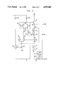
FIG. 3 illustrates a second embodiment of the present invention; and
FIG. 4 illustrates a graph depicting the output of the bandgap voltage reference of the present invention.
DETAILED DESCRIPTION OF THE INVENTION
The preferred embodiment of the present invention is best understood by referring to FIGS. 1-4 of the drawings, like numerals being used for like and corresponding parts of the various drawings.
FIG. 1 illustrates a schematic representation of a prior art bandgap voltage reference circuit. The circuit 10 comprises a reference current source 12 connected to the collector 14 and base 16 of the a NPN transistor 18. The emitter 20 of the NPN transistor to one end of a resistor R1. The other end of the resistor R1 is connected to ground. The voltage reference Vref is provided between the base 16 and ground.
The current source provides a current equal to Vptat /R0. Vptat is a voltage which is proportional to absolute temperature. The reference voltage Vref equals the base emitter voltage Vbe of the transistor 18 plus the voltage created by the current through R1. Hence, Vref =Vbe +Vptat *(R1 /R0). By selecting appropriate values for R1 and R0, the temperature dependence of the base emitter voltage Vbe can be compensated by the voltage drop across R1.
While the circuit of FIG. 1 provides a relatively stable voltage over a moderate temperature range, second order effects will cause voltage dropoffs at very low and very high temperatures. Consequently, the circuit of FIG. 1 is inappropriate where the integrated circuit will be subjected to a wide temperature range.
FIG. 2 illustrates a schematic representation of the present invention. The curvature corrected bandgap circuit 22 comprises a reference current source section 24, a bandgap circuit section 26, and a curvature correction circuit 28.
The reference circuit section 24 generates a current Iptat which is relatively constant over temperature. The reference circuit section 24 is designed such that Iptat =Vptat /R0 where R0 is a resistor included in the current source 30. Both Vptat and R0 are temperature dependent, and tend to cancel out one another, resulting in a relatively temperature independent Iptat.
Iptat is mirrored through transistors 32 and 34 to supply the current Iptat to the curvature correction circuit 28.
The curvature correction circuit 28 comprises a high-temp compensation circuit 36 and a low-temp compensation circuit 38. The high-temp compensation circuit 36 comprises an NPN transistor 40 having its base connected to a resistor R3 and to a collector of PNP transistor 34. The collector of transistor 40 is connected to a node 41 in the bandgap circuit 26. The emitter of transistor 40 is connected to a resistor R4. The opposite ends of resistors R3 and R4 are connected to the collector of an NPN transistor 42. The emitter of collector 42 is connected to circuit common. The base of transistor 42 is connected to its collector and to the bases of NPN transistors 44 and 46. The low-temp compensation circuit 38 comprises resistors R5 and R6, each having one end connected to the output node 48 of the bandgap circuit 26. The opposite end of resistor R5 is connected to the emitter of PNP transistor 50. The opposite end of resistor R6 is connected to the collector of transistor 46, the base of transistor 50, and the base of transistor 52. The emitters of transistors 44 and 46 are connected to the circuit common. The collector of transistor 44 is connected to the collector of transistor 50 and the emitter of transistor 52. The collector of transistor 52 is connected to a node 53 in the bandgap circuit 26.
Bandgap circuit 26 comprises a current mirror including PNP transistors 54a-b, both having emitters connected to a collector of transistor 34. The bases of transistors 54a-b are connected to the collector of transistor 54a. The collectors of transistors 54a-b are connected to the collectors of NPN transistors 55 and 56, respectively. The emitters of transistors 55 and 56 are connected to the collector of NPN transistor 58. The emitter of transistor 58 is connected to the circuit common through resistor R7. The base of transistor 58 is connected to the base and collector of transistor 60. The emitters of transistors 54a-b are also connected to the base of an NPN transistor 62. The collector of transistor 62 is connected to Vcc and the emitter of transistor 62 is connected to node 48. Between nodes 48 and 53, a resistor RLT is connected. Between nodes 53 and 41, a resistor RHT is connected. Also connected to node 41 are the collector and base of an NPN transistor 64. The emitter of transistor 64 is connected to the collector and base of an NPN transistor 66. The emitter of transistor 66 is connected to a resistor R8. The other end of resistor R8 is connected to a node 68 which is connected to the base of transistor 56. The base of transistor 55 is connected to a node 70. A resistor R9 is connected between nodes 68 and 70. Also connected to node 70 is the collector and base of an NPN transistor 72. The emitter of transistor 72 is connected to the collector and base of an NPN transistor 74. A resistor R10 connects the emitter of transistor 74 with circuit common. An intermediate gain stage circuit 76 comprises a PNP transistor 78, having a emitter connected to the base of transistor 62, a base connected to the collector of transistor 54b and an collector connected to the base of an NPN transistor 80. A capacitor 82 is connected between the base and collector of transistor 78. The collector of transistor 80 is connected to the emitter of transistor 78. A resistor 84 is connected between the base and emitter of transistor 80. The emitter of transistor 80 is connected to the circuit common.
Notably, resistors R0, R3, and R6 are made from the same material, such that these temperature coefficients will be substantially identical. Hence the voltages through R6 will be proportional Vptat, which is dependent upon temperature.
In operation, the circuit 26 operates similar to a typical bandgap circuit, such as one shown in FIG. 1, in a temperature range between T0 and T1, where the output voltage is relatively constant. In this temperature range, transistors 54a-b force equal currents through transistors 55 and 56. Transistors 55 and 56 have a specified emitter area ratio, shown in FIG. 2 as 5:1. Hence, a voltage ΔVbe develops between the bases of the transistors 55 and 56. Since the bases of transistors 55 and 56 are connected across resistor R9, a current develops through resistor R9 equal to ΔVbe /R9. Hence, the output voltage between node 48 and ground can be shown to be:
V.sub.out =4V.sub.be +(R.sub.tot /R.sub.9) ΔV.sub.be
where,
4Vbe =the combined base emitter voltages of transistors 64, 66, 72 and 74
Rtot =RLT +RHT +R8 +R9 +R10, and
ΔVbe =kT/q ln5.
Gain stage circuit 76 operates to maintain an equal current through transistors 54a-b by loading transistor 56 insignificantly.
At temperatures greater than T1, the high temperature compensation circuit 36 is enabled. As temperatures increase, the voltage drop over resistor R3 similarly increases. When the voltage across R3 reaches a predetermined voltage, the transistor 40 will begin to turn on, thereby drawing additional current through resistors RLT and RHT. Hence, the high temperature compensation circuit 36 acts to increase the output voltage at higher temperature. As temperature increases, transistor 40 will draw more current to further increase the output voltage. Resistor R4 is provided to implement a gradual change in current through transistor 40 as temperature increases.
Similarly, the low temperature compensation circuit 38 boosts the output voltage at temperatures below T0. Transistors 44 and 46 mirror the current through transistor 42. Hence, transistors 44 and 46 will draw current equal to Iptat. At low temperatures, the voltage across resistor R6 will be low. Resistor R6 has a value such that at temperatures below T0, the PNP transistor 50 will not turn on. Hence, the current drawn by transistor 44 must be drawn through transistor 52. Since the collector of transistor 52 is connected to node 53, an additional voltage is drawn through resistor RLT, thereby increasing the output voltage Vout. As temperature increases, the voltage across R6 will increase causing PNP transistor 50 to conduct. As transistor 50 conducts, the current through transistor 52 will decrease, reducing the voltage drop across RLT.
The temperatures at which the curvature correction circuit affects the output voltage may be varied by adjusting resistors R6 and R3, along with resistor R0. Hence, the curvature correction circuit 28 is operable to provide curvature correction at any two temperatures. Further, additional circuits similar to the high temperature compensation circuit 36 and low temperature compensation circuit 38 may be used to provide further curvature correction.
FIG. 3 illustrates a second embodiment of the present invention wherein the high temperature correction circuit is driven by the bandgap voltage circuit, without the need for a separate reference current section 24. The bandgap circuit 26 is essentially the same as shown in FIG. 3. However, the high temperature compensation circuit 36 comprises a transistor 86 having a base connected to the emitter of transistor 74. The collector of the transistor 86 is connected to node 53 and the emitter of transistor 86 is connected to circuit common through resistor R1l. It should be noted that RLT is not present in this embodiment of the invention since only the high temperature compensation circuit 36 is present. However, it would possible to provide a low temperature compensation circuit as shown in FIG. 2 in the embodiment of FIG. 3.
As previously discussed, at a certain temperature T1, the output voltage Vout will decrease due to diode drops of transistors 64, 66, 72 and 74 decreasing faster than the voltage across the resistors R8, R9, and R10 is increasing. The voltage across R10 will increase as temperature increases. R10 may be provided a value such that at temperature T1, the transistor 86 is enabled. When transistor 86 is enabled, additional current will be drawn through RHT, thereby increasing the output voltage. Resistor R10 may be adjusted to enable the transistor 86 at a desired temperature. Resistor R1l is provided to gradually increase the current through transistor 86 with temperature.
FIG. 4 illustrates a graph depicting the output voltage of the bandgap circuit 22 of FIG. 3 having high temperature curvature correction. As can be seen, the output voltage is relatively stable within ten millivolts over a temperature range from -40° F. to 120° F.
The present invention provides the technical advantage that additional compensation may be enabled at high and low temperatures in order to provide a more constant reference voltage over a wide temperature range. The temperature at which the additional compensation is provided may be varied by adjusting the values of one or more resistors. The circuit of the present invention requires minimal additional hardware to accomplish the compensation.
Although the present invention has been described in detail, it should be understood that various changes, substitutions and alterations can be made herein without departing from the spirit and scope of the invention as defined by the appended claims.

Claims (13)

What is claimed is:
1. A circuit for generating a stable reference voltage over a wide temperature range, comprising:
a voltage generator for providing a relatively stable output voltage within a known temperature range, said generator including (i) first and second mismatched bipolar transistors, the emitters of said first and second bipolar transistors tied together, (ii) a first resistor connected between the bases of said first and second bipolar transistors, and (iii) a second resistor in series with said first resistor and passing said first current, said generator providing said relatively stable output voltage from current determined by said first resistor; and
circuitry for adjusting said output voltage responsive to a predetermined temperature to maintain a stable output voltage, said circuitry providing current at through said second resistor and parallel said first resistor for temperatures outside of said known temperature range.
2. The circuit of claim 1 wherein said voltage generator comprises a bandgap voltage reference.
3. The circuit of claim 1 wherein said adjusting circuitry comprises:
a circuit for generating a temperature dependent voltage; and
a circuit for generating a current responsive to said temperature dependent voltage.
4. The circuit of claim 3 wherein said circuit for generating a voltage comprises a resistor.
5. The circuit of claim 3 wherein said circuit for generating a current comprises a transistor.
6. The circuit of claim 1 wherein said voltage generator includes one or more resistors through which a current is driven.
7. The circuit of claim 6 wherein said adjusting circuitry comprises circuitry to adjust the current through one or more of said resistors such that the voltage across the resistors is varied.
8. The circuit of claim 1 wherein said adjusting circuitry comprises first adjusting circuitry to adjust the output voltage in response to a first temperature and second adjusting circuitry to adjust the output voltage in response to a second temperature.
9. The method of generating a stable output voltage reference comprising the steps of:
generating a relatively stable output voltage over a known temperature range by the use of emitter tied mismatched bipolar transistors with bases connected by a first resistor and with said relatively stable output voltage determined by a first current through said first resistor;
detecting a predetermined temperature; and
adjusting said output voltage in response to said temperature detection in order to provide a stable voltage reference by drawing a second current through a second resistor, said second resistor in series with said first resistor and said second resistor passing said first current.
10. The method of claim 9 wherein said detection step comprises:
generating a temperature dependent voltage; and
detecting a predetermined voltage level.
11. The method of claim 10 wherein said adjusting step comprises the step of enabling a transistor responsive to detecting said predetermined voltage level.
12. The method of claim 11 wherein said step of generating a relatively stable output voltage comprises the step of drawing current through one or more resistors.
13. The method of claim 12 wherein said adjusting step further comprises the step of adjusting the amount of current through one or more of said resistors.
US07/330,660 1989-03-30 1989-03-30 Bandgap voltage reference and method with further temperature correction Expired - Lifetime US4939442A (en)

Priority Applications (2)

Application Number Priority Date Filing Date Title
US07/330,660 US4939442A (en) 1989-03-30 1989-03-30 Bandgap voltage reference and method with further temperature correction
JP2082902A JP2854919B2 (en) 1989-03-30 1990-03-29 Circuit that generates reference voltage

Applications Claiming Priority (1)

Application Number Priority Date Filing Date Title
US07/330,660 US4939442A (en) 1989-03-30 1989-03-30 Bandgap voltage reference and method with further temperature correction

Publications (1)

Publication Number Publication Date
US4939442A true US4939442A (en) 1990-07-03

Family

ID=23290743

Family Applications (1)

Application Number Title Priority Date Filing Date
US07/330,660 Expired - Lifetime US4939442A (en) 1989-03-30 1989-03-30 Bandgap voltage reference and method with further temperature correction

Country Status (2)

Country Link
US (1) US4939442A (en)
JP (1) JP2854919B2 (en)

Cited By (60)

* Cited by examiner, † Cited by third party
Publication number Priority date Publication date Assignee Title
US5001414A (en) * 1988-11-23 1991-03-19 Thomson Microelectronics Voltage reference circuit with linearized temperature behavior
WO1993009599A2 (en) * 1991-10-30 1993-05-13 Harris Corporation Analog-to-digital converter and method of fabrication
EP0557739A1 (en) * 1992-02-26 1993-09-01 Motorola, Inc. A thermally dependent self-modifying voltage source
US5258702A (en) * 1989-04-01 1993-11-02 Robert Bosch Gmbh Precision reference voltage source
US5289111A (en) * 1991-05-17 1994-02-22 Rohm Co., Ltd. Bandgap constant voltage circuit
US5339018A (en) * 1989-06-30 1994-08-16 Analog Devices, Inc. Integrated circuit monitor for storage battery voltage and temperature
US5349286A (en) * 1993-06-18 1994-09-20 Texas Instruments Incorporated Compensation for low gain bipolar transistors in voltage and current reference circuits
US5352973A (en) * 1993-01-13 1994-10-04 Analog Devices, Inc. Temperature compensation bandgap voltage reference and method
US5391980A (en) * 1993-06-16 1995-02-21 Texas Instruments Incorporated Second order low temperature coefficient bandgap voltage supply
EP0640904A2 (en) * 1993-08-30 1995-03-01 Motorola, Inc. Curvature correction circuit for a voltage reference
US5471131A (en) * 1991-10-30 1995-11-28 Harris Corporation Analog-to-digital converter and reference voltage circuitry
US5523660A (en) * 1993-07-06 1996-06-04 Rohm Co., Ltd. Motor control circuit and motor drive system using the same
US5530395A (en) * 1995-04-03 1996-06-25 Etron Technology Inc. Supply voltage level control using reference voltage generator and comparator circuits
WO1997034212A1 (en) * 1996-03-12 1997-09-18 Maxim Integrated Products, Inc. Methods and apparatus for improving temperature drift of references
US5684394A (en) * 1994-06-28 1997-11-04 Texas Instruments Incorporated Beta helper for voltage and current reference circuits
US5686823A (en) * 1996-08-07 1997-11-11 National Semiconductor Corporation Bandgap voltage reference circuit
US5760639A (en) * 1996-03-04 1998-06-02 Motorola, Inc. Voltage and current reference circuit with a low temperature coefficient
US5834926A (en) * 1997-08-11 1998-11-10 Motorola, Inc. Bandgap reference circuit
US5856742A (en) * 1995-06-30 1999-01-05 Harris Corporation Temperature insensitive bandgap voltage generator tracking power supply variations
US6002243A (en) * 1998-09-02 1999-12-14 Texas Instruments Incorporated MOS circuit stabilization of bipolar current mirror collector voltages
US6018265A (en) * 1997-12-10 2000-01-25 Lexar Media, Inc. Internal CMOS reference generator and voltage regulator
US6060874A (en) * 1999-07-22 2000-05-09 Burr-Brown Corporation Method of curvature compensation, offset compensation, and capacitance trimming of a switched capacitor band gap reference
EP1041480A1 (en) * 1999-03-29 2000-10-04 Texas Instruments Incorporated Bandgap circuits with curvature-correction
FR2801116A1 (en) * 1999-11-15 2001-05-18 St Microelectronics Sa CORRECTED VOLTAGE GENERATOR DEVICE AT LOW TEMPERATURE
US6255807B1 (en) 2000-10-18 2001-07-03 Texas Instruments Tucson Corporation Bandgap reference curvature compensation circuit
US6404246B1 (en) 2000-12-20 2002-06-11 Lexa Media, Inc. Precision clock synthesizer using RC oscillator and calibration circuit
US6465997B2 (en) * 2000-09-15 2002-10-15 Stmicroelectronics S.A. Regulated voltage generator for integrated circuit
KR20030012753A (en) * 2001-08-04 2003-02-12 허일 Self-Start-Up Voltage Stabilization Circuit
US6642699B1 (en) 2002-04-29 2003-11-04 Ami Semiconductor, Inc. Bandgap voltage reference using differential pairs to perform temperature curvature compensation
US6657480B2 (en) * 2000-07-21 2003-12-02 Ixys Corporation CMOS compatible band gap reference
US20040066180A1 (en) * 2002-10-04 2004-04-08 Intersil Americas Inc. Non-linear current generator for high-order temperature-compensated references
US20040239411A1 (en) * 2003-05-29 2004-12-02 Somerville Thomas A. Delta Vgs curvature correction for bandgap reference voltage generation
US6828847B1 (en) 2003-02-27 2004-12-07 Analog Devices, Inc. Bandgap voltage reference circuit and method for producing a temperature curvature corrected voltage reference
US20050073290A1 (en) * 2003-10-07 2005-04-07 Stefan Marinca Method and apparatus for compensating for temperature drift in semiconductor processes and circuitry
US20050122091A1 (en) * 2003-12-09 2005-06-09 Analog Devices, Inc. Bandgap voltage reference
US20050151528A1 (en) * 2004-01-13 2005-07-14 Analog Devices, Inc. Low offset bandgap voltage reference
US20050218967A1 (en) * 2003-10-09 2005-10-06 Stmicroelectronics Limited Reference circuitry and method of operating the same
US20060132201A1 (en) * 2004-12-17 2006-06-22 Barnett Raymond E Low power, power on reset circuit with accurate supply voltage detection
US7193454B1 (en) 2004-07-08 2007-03-20 Analog Devices, Inc. Method and a circuit for producing a PTAT voltage, and a method and a circuit for producing a bandgap voltage reference
US7248098B1 (en) * 2004-03-24 2007-07-24 National Semiconductor Corporation Curvature corrected bandgap circuit
US20080074172A1 (en) * 2006-09-25 2008-03-27 Analog Devices, Inc. Bandgap voltage reference and method for providing same
US7420359B1 (en) * 2006-03-17 2008-09-02 Linear Technology Corporation Bandgap curvature correction and post-package trim implemented therewith
US20080224759A1 (en) * 2007-03-13 2008-09-18 Analog Devices, Inc. Low noise voltage reference circuit
US20080265860A1 (en) * 2007-04-30 2008-10-30 Analog Devices, Inc. Low voltage bandgap reference source
US7453252B1 (en) * 2004-08-24 2008-11-18 National Semiconductor Corporation Circuit and method for reducing reference voltage drift in bandgap circuits
US20090160538A1 (en) * 2007-12-21 2009-06-25 Analog Devices, Inc. Low voltage current and voltage generator
US20090160537A1 (en) * 2007-12-21 2009-06-25 Analog Devices, Inc. Bandgap voltage reference circuit
US20090243713A1 (en) * 2008-03-25 2009-10-01 Analog Devices, Inc. Reference voltage circuit
US20090243711A1 (en) * 2008-03-25 2009-10-01 Analog Devices, Inc. Bias current generator
US20090243708A1 (en) * 2008-03-25 2009-10-01 Analog Devices, Inc. Bandgap voltage reference circuit
US7605578B2 (en) 2007-07-23 2009-10-20 Analog Devices, Inc. Low noise bandgap voltage reference
US8102201B2 (en) 2006-09-25 2012-01-24 Analog Devices, Inc. Reference circuit and method for providing a reference
US20120094613A1 (en) * 2010-10-15 2012-04-19 Fujitsu Semiconductor Limited Temperature dependent voltage regulator
US20130234692A1 (en) * 2012-03-07 2013-09-12 Medtronic, Inc. Voltage supply and method with two references having differing accuracy and power consumption
US20130249527A1 (en) * 2010-02-12 2013-09-26 Texas Instruments Incorporated Electronic Device and Method for Generating a Curvature Compensated Bandgap Reference Voltage
CN103558896A (en) * 2013-11-05 2014-02-05 苏州贝克微电子有限公司 Fixed voltage reference circuit
US8791683B1 (en) * 2011-02-28 2014-07-29 Linear Technology Corporation Voltage-mode band-gap reference circuit with temperature drift and output voltage trims
US20150123643A1 (en) * 2006-06-02 2015-05-07 Dolpan Audio, Llc Bandgap circuit with temperature correction
CN107272818A (en) * 2017-06-27 2017-10-20 福建省福芯电子科技有限公司 A kind of high voltage band-gap reference circuit structure
US9864389B1 (en) 2016-11-10 2018-01-09 Analog Devices Global Temperature compensated reference voltage circuit

Families Citing this family (3)

* Cited by examiner, † Cited by third party
Publication number Priority date Publication date Assignee Title
JP4513209B2 (en) * 2000-12-28 2010-07-28 富士電機システムズ株式会社 Semiconductor integrated circuit
JP6972705B2 (en) * 2017-06-28 2021-11-24 株式会社デンソー Electronic device
JP6927070B2 (en) * 2018-02-02 2021-08-25 株式会社デンソー Corrected current output circuit and reference voltage circuit with correction function

Citations (10)

* Cited by examiner, † Cited by third party
Publication number Priority date Publication date Assignee Title
US4325018A (en) * 1980-08-14 1982-04-13 Rca Corporation Temperature-correction network with multiple corrections as for extrapolated band-gap voltage reference circuits
US4525663A (en) * 1982-08-03 1985-06-25 Burr-Brown Corporation Precision band-gap voltage reference circuit
JPS6134617A (en) * 1984-07-27 1986-02-18 Fujitsu Ltd Reference voltage generating circuit
US4603291A (en) * 1984-06-26 1986-07-29 Linear Technology Corporation Nonlinearity correction circuit for bandgap reference
US4633165A (en) * 1984-08-15 1986-12-30 Precision Monolithics, Inc. Temperature compensated voltage reference
SU1283729A1 (en) * 1985-07-10 1987-01-15 Ленинградский электротехнический институт им.В.И.Ульянова (Ленина) D.c.voltage stabilezer
US4668903A (en) * 1985-08-15 1987-05-26 Thaler Corporation Apparatus and method for a temperature compensated reference voltage supply
GB2199677A (en) * 1986-12-29 1988-07-13 Motorola Inc Bandgap voltage reference circuit
US4789819A (en) * 1986-11-18 1988-12-06 Linear Technology Corporation Breakpoint compensation and thermal limit circuit
US4808908A (en) * 1988-02-16 1989-02-28 Analog Devices, Inc. Curvature correction of bipolar bandgap references

Family Cites Families (3)

* Cited by examiner, † Cited by third party
Publication number Priority date Publication date Assignee Title
US4059793A (en) * 1976-08-16 1977-11-22 Rca Corporation Semiconductor circuits for generating reference potentials with predictable temperature coefficients
JP2745553B2 (en) * 1988-08-22 1998-04-28 ミツミ電機株式会社 Low voltage reference power supply circuit
JP2745610B2 (en) * 1988-12-29 1998-04-28 ミツミ電機株式会社 Low voltage reference power supply circuit

Patent Citations (10)

* Cited by examiner, † Cited by third party
Publication number Priority date Publication date Assignee Title
US4325018A (en) * 1980-08-14 1982-04-13 Rca Corporation Temperature-correction network with multiple corrections as for extrapolated band-gap voltage reference circuits
US4525663A (en) * 1982-08-03 1985-06-25 Burr-Brown Corporation Precision band-gap voltage reference circuit
US4603291A (en) * 1984-06-26 1986-07-29 Linear Technology Corporation Nonlinearity correction circuit for bandgap reference
JPS6134617A (en) * 1984-07-27 1986-02-18 Fujitsu Ltd Reference voltage generating circuit
US4633165A (en) * 1984-08-15 1986-12-30 Precision Monolithics, Inc. Temperature compensated voltage reference
SU1283729A1 (en) * 1985-07-10 1987-01-15 Ленинградский электротехнический институт им.В.И.Ульянова (Ленина) D.c.voltage stabilezer
US4668903A (en) * 1985-08-15 1987-05-26 Thaler Corporation Apparatus and method for a temperature compensated reference voltage supply
US4789819A (en) * 1986-11-18 1988-12-06 Linear Technology Corporation Breakpoint compensation and thermal limit circuit
GB2199677A (en) * 1986-12-29 1988-07-13 Motorola Inc Bandgap voltage reference circuit
US4808908A (en) * 1988-02-16 1989-02-28 Analog Devices, Inc. Curvature correction of bipolar bandgap references

Non-Patent Citations (6)

* Cited by examiner, † Cited by third party
Title
"A New Curvature-Corrected Bandgap Reference", Gerard Meijer, Peter C. Schmale and Klaas Van Zalinge, 1982 IEEE Journal of Solid-State Circuits, vol. SC-17 No. 6 Dec., 1982, pp. 1139-1143.
"Session VI: Data Acquisition Circuits, A Curvature Corrected Micropower Voltage Reference", Carl R. Palmer and Robert C. Dobkin, 1981 IEEE International Solid-State Circuits Conf., pp. 58-59.
A New Curvature Corrected Bandgap Reference , Gerard Meijer, Peter C. Schmale and Klaas Van Zalinge, 1982 IEEE Journal of Solid State Circuits, vol. SC 17 No. 6 Dec., 1982, pp. 1139 1143. *
Martin, "Temperature Sensing and Compensating Reference Voltage Supplies," IBM Tech. Discl. Bul., vol. 7, No. 5, pp. 357-358, (10-1964).
Martin, Temperature Sensing and Compensating Reference Voltage Supplies, IBM Tech. Discl. Bul., vol. 7, No. 5, pp. 357 358, (10 1964). *
Session VI: Data Acquisition Circuits, A Curvature Corrected Micropower Voltage Reference , Carl R. Palmer and Robert C. Dobkin, 1981 IEEE International Solid State Circuits Conf., pp. 58 59. *

Cited By (87)

* Cited by examiner, † Cited by third party
Publication number Priority date Publication date Assignee Title
US5001414A (en) * 1988-11-23 1991-03-19 Thomson Microelectronics Voltage reference circuit with linearized temperature behavior
US5258702A (en) * 1989-04-01 1993-11-02 Robert Bosch Gmbh Precision reference voltage source
US5339018A (en) * 1989-06-30 1994-08-16 Analog Devices, Inc. Integrated circuit monitor for storage battery voltage and temperature
US5289111A (en) * 1991-05-17 1994-02-22 Rohm Co., Ltd. Bandgap constant voltage circuit
US5471131A (en) * 1991-10-30 1995-11-28 Harris Corporation Analog-to-digital converter and reference voltage circuitry
WO1993009599A3 (en) * 1991-10-30 1993-08-05 Harris Corp Analog-to-digital converter and method of fabrication
WO1993009599A2 (en) * 1991-10-30 1993-05-13 Harris Corporation Analog-to-digital converter and method of fabrication
EP0557739A1 (en) * 1992-02-26 1993-09-01 Motorola, Inc. A thermally dependent self-modifying voltage source
US5352973A (en) * 1993-01-13 1994-10-04 Analog Devices, Inc. Temperature compensation bandgap voltage reference and method
US5391980A (en) * 1993-06-16 1995-02-21 Texas Instruments Incorporated Second order low temperature coefficient bandgap voltage supply
EP0629938A3 (en) * 1993-06-18 1997-08-20 Texas Instruments Inc Compensation for low gain bipolar transistors in voltage and current reference circuits.
US5349286A (en) * 1993-06-18 1994-09-20 Texas Instruments Incorporated Compensation for low gain bipolar transistors in voltage and current reference circuits
EP0629938A2 (en) * 1993-06-18 1994-12-21 Texas Instruments Incorporated Compensation for low gain bipolar transistors in voltage and current reference circuits
US5523660A (en) * 1993-07-06 1996-06-04 Rohm Co., Ltd. Motor control circuit and motor drive system using the same
EP0640904A2 (en) * 1993-08-30 1995-03-01 Motorola, Inc. Curvature correction circuit for a voltage reference
EP0640904A3 (en) * 1993-08-30 1997-06-04 Motorola Inc Curvature correction circuit for a voltage reference.
US5684394A (en) * 1994-06-28 1997-11-04 Texas Instruments Incorporated Beta helper for voltage and current reference circuits
US5530395A (en) * 1995-04-03 1996-06-25 Etron Technology Inc. Supply voltage level control using reference voltage generator and comparator circuits
US5856742A (en) * 1995-06-30 1999-01-05 Harris Corporation Temperature insensitive bandgap voltage generator tracking power supply variations
US5760639A (en) * 1996-03-04 1998-06-02 Motorola, Inc. Voltage and current reference circuit with a low temperature coefficient
WO1997034212A1 (en) * 1996-03-12 1997-09-18 Maxim Integrated Products, Inc. Methods and apparatus for improving temperature drift of references
US5686823A (en) * 1996-08-07 1997-11-11 National Semiconductor Corporation Bandgap voltage reference circuit
US5834926A (en) * 1997-08-11 1998-11-10 Motorola, Inc. Bandgap reference circuit
US6018265A (en) * 1997-12-10 2000-01-25 Lexar Media, Inc. Internal CMOS reference generator and voltage regulator
US6002243A (en) * 1998-09-02 1999-12-14 Texas Instruments Incorporated MOS circuit stabilization of bipolar current mirror collector voltages
EP1041480A1 (en) * 1999-03-29 2000-10-04 Texas Instruments Incorporated Bandgap circuits with curvature-correction
US6060874A (en) * 1999-07-22 2000-05-09 Burr-Brown Corporation Method of curvature compensation, offset compensation, and capacitance trimming of a switched capacitor band gap reference
US6407638B1 (en) 1999-11-15 2002-06-18 Stmicroelectronics S.A. Low temperature-corrected voltage generator device
EP1102148A1 (en) * 1999-11-15 2001-05-23 STMicroelectronics SA Low temperature corrected voltage generating device
FR2801116A1 (en) * 1999-11-15 2001-05-18 St Microelectronics Sa CORRECTED VOLTAGE GENERATOR DEVICE AT LOW TEMPERATURE
US6657480B2 (en) * 2000-07-21 2003-12-02 Ixys Corporation CMOS compatible band gap reference
US6465997B2 (en) * 2000-09-15 2002-10-15 Stmicroelectronics S.A. Regulated voltage generator for integrated circuit
US6255807B1 (en) 2000-10-18 2001-07-03 Texas Instruments Tucson Corporation Bandgap reference curvature compensation circuit
US6404246B1 (en) 2000-12-20 2002-06-11 Lexa Media, Inc. Precision clock synthesizer using RC oscillator and calibration circuit
KR20030012753A (en) * 2001-08-04 2003-02-12 허일 Self-Start-Up Voltage Stabilization Circuit
US6642699B1 (en) 2002-04-29 2003-11-04 Ami Semiconductor, Inc. Bandgap voltage reference using differential pairs to perform temperature curvature compensation
US20040066180A1 (en) * 2002-10-04 2004-04-08 Intersil Americas Inc. Non-linear current generator for high-order temperature-compensated references
US6791307B2 (en) * 2002-10-04 2004-09-14 Intersil Americas Inc. Non-linear current generator for high-order temperature-compensated references
US6828847B1 (en) 2003-02-27 2004-12-07 Analog Devices, Inc. Bandgap voltage reference circuit and method for producing a temperature curvature corrected voltage reference
US20040239411A1 (en) * 2003-05-29 2004-12-02 Somerville Thomas A. Delta Vgs curvature correction for bandgap reference voltage generation
US6856189B2 (en) 2003-05-29 2005-02-15 Standard Microsystems Corporation Delta Vgs curvature correction for bandgap reference voltage generation
US20050073290A1 (en) * 2003-10-07 2005-04-07 Stefan Marinca Method and apparatus for compensating for temperature drift in semiconductor processes and circuitry
US7543253B2 (en) 2003-10-07 2009-06-02 Analog Devices, Inc. Method and apparatus for compensating for temperature drift in semiconductor processes and circuitry
US20050218967A1 (en) * 2003-10-09 2005-10-06 Stmicroelectronics Limited Reference circuitry and method of operating the same
US20050122091A1 (en) * 2003-12-09 2005-06-09 Analog Devices, Inc. Bandgap voltage reference
US7012416B2 (en) 2003-12-09 2006-03-14 Analog Devices, Inc. Bandgap voltage reference
US7211993B2 (en) 2004-01-13 2007-05-01 Analog Devices, Inc. Low offset bandgap voltage reference
US20070170906A1 (en) * 2004-01-13 2007-07-26 Analog Devices, Inc. Temperature reference circuit
US7372244B2 (en) 2004-01-13 2008-05-13 Analog Devices, Inc. Temperature reference circuit
US20050151528A1 (en) * 2004-01-13 2005-07-14 Analog Devices, Inc. Low offset bandgap voltage reference
US7248098B1 (en) * 2004-03-24 2007-07-24 National Semiconductor Corporation Curvature corrected bandgap circuit
US7193454B1 (en) 2004-07-08 2007-03-20 Analog Devices, Inc. Method and a circuit for producing a PTAT voltage, and a method and a circuit for producing a bandgap voltage reference
US7453252B1 (en) * 2004-08-24 2008-11-18 National Semiconductor Corporation Circuit and method for reducing reference voltage drift in bandgap circuits
US7812649B2 (en) * 2004-12-17 2010-10-12 Texas Instruments Incorporated Low power, power on reset circuit with accurate supply voltage detection
US20060132201A1 (en) * 2004-12-17 2006-06-22 Barnett Raymond E Low power, power on reset circuit with accurate supply voltage detection
US7420359B1 (en) * 2006-03-17 2008-09-02 Linear Technology Corporation Bandgap curvature correction and post-package trim implemented therewith
US9671800B2 (en) * 2006-06-02 2017-06-06 Ol Security Limited Liability Company Bandgap circuit with temperature correction
US20150123643A1 (en) * 2006-06-02 2015-05-07 Dolpan Audio, Llc Bandgap circuit with temperature correction
US8102201B2 (en) 2006-09-25 2012-01-24 Analog Devices, Inc. Reference circuit and method for providing a reference
US7576598B2 (en) 2006-09-25 2009-08-18 Analog Devices, Inc. Bandgap voltage reference and method for providing same
US20080074172A1 (en) * 2006-09-25 2008-03-27 Analog Devices, Inc. Bandgap voltage reference and method for providing same
US20080224759A1 (en) * 2007-03-13 2008-09-18 Analog Devices, Inc. Low noise voltage reference circuit
US7714563B2 (en) 2007-03-13 2010-05-11 Analog Devices, Inc. Low noise voltage reference circuit
US20080265860A1 (en) * 2007-04-30 2008-10-30 Analog Devices, Inc. Low voltage bandgap reference source
US7605578B2 (en) 2007-07-23 2009-10-20 Analog Devices, Inc. Low noise bandgap voltage reference
US7598799B2 (en) 2007-12-21 2009-10-06 Analog Devices, Inc. Bandgap voltage reference circuit
US7612606B2 (en) 2007-12-21 2009-11-03 Analog Devices, Inc. Low voltage current and voltage generator
WO2009080558A1 (en) * 2007-12-21 2009-07-02 Analog Devices, Inc. A bandgap voltage reference circuit
US20090160538A1 (en) * 2007-12-21 2009-06-25 Analog Devices, Inc. Low voltage current and voltage generator
US20090160537A1 (en) * 2007-12-21 2009-06-25 Analog Devices, Inc. Bandgap voltage reference circuit
US20090243708A1 (en) * 2008-03-25 2009-10-01 Analog Devices, Inc. Bandgap voltage reference circuit
US20090243711A1 (en) * 2008-03-25 2009-10-01 Analog Devices, Inc. Bias current generator
US7750728B2 (en) 2008-03-25 2010-07-06 Analog Devices, Inc. Reference voltage circuit
US20090243713A1 (en) * 2008-03-25 2009-10-01 Analog Devices, Inc. Reference voltage circuit
US7880533B2 (en) 2008-03-25 2011-02-01 Analog Devices, Inc. Bandgap voltage reference circuit
US7902912B2 (en) 2008-03-25 2011-03-08 Analog Devices, Inc. Bias current generator
US20130249527A1 (en) * 2010-02-12 2013-09-26 Texas Instruments Incorporated Electronic Device and Method for Generating a Curvature Compensated Bandgap Reference Voltage
US9104217B2 (en) * 2010-02-12 2015-08-11 Texas Instruments Incorporated Electronic device and method for generating a curvature compensated bandgap reference voltage
US20150331439A1 (en) * 2010-02-12 2015-11-19 Texas Instruments Incorporated Electronic Device and Method for Generating a Curvature Compensated Bandgap Reference Voltage
US9372496B2 (en) * 2010-02-12 2016-06-21 Texas Instruments Incorporated Electronic device and method for generating a curvature compensated bandgap reference voltage
US8922178B2 (en) * 2010-10-15 2014-12-30 Intel IP Corporation Temperature dependent voltage regulator
US20120094613A1 (en) * 2010-10-15 2012-04-19 Fujitsu Semiconductor Limited Temperature dependent voltage regulator
US8791683B1 (en) * 2011-02-28 2014-07-29 Linear Technology Corporation Voltage-mode band-gap reference circuit with temperature drift and output voltage trims
US20130234692A1 (en) * 2012-03-07 2013-09-12 Medtronic, Inc. Voltage supply and method with two references having differing accuracy and power consumption
CN103558896A (en) * 2013-11-05 2014-02-05 苏州贝克微电子有限公司 Fixed voltage reference circuit
US9864389B1 (en) 2016-11-10 2018-01-09 Analog Devices Global Temperature compensated reference voltage circuit
CN107272818A (en) * 2017-06-27 2017-10-20 福建省福芯电子科技有限公司 A kind of high voltage band-gap reference circuit structure

Also Published As

Publication number Publication date
JP2854919B2 (en) 1999-02-10
JPH02285408A (en) 1990-11-22

Similar Documents

Publication Publication Date Title
US4939442A (en) Bandgap voltage reference and method with further temperature correction
US4352056A (en) Solid-state voltage reference providing a regulated voltage having a high magnitude
US4789819A (en) Breakpoint compensation and thermal limit circuit
US4808908A (en) Curvature correction of bipolar bandgap references
US6016051A (en) Bandgap reference voltage circuit with PTAT current source
US5424628A (en) Bandgap reference with compensation via current squaring
US5900772A (en) Bandgap reference circuit and method
US5596265A (en) Band gap voltage compensation circuit
US3887863A (en) Solid-state regulated voltage supply
US6956727B1 (en) High side current monitor with extended voltage range
US20030198114A1 (en) Proportional to temperature voltage generator
US4727337A (en) Protection circuit for RF power amplifiers
EP0656575B1 (en) Band-gap reference current source with compensation for saturating current spread of bipolar transistor
US7208930B1 (en) Bandgap voltage regulator
US4633165A (en) Temperature compensated voltage reference
US6294902B1 (en) Bandgap reference having power supply ripple rejection
USRE30586E (en) Solid-state regulated voltage supply
US4446419A (en) Current stabilizing arrangement
EP0288939B1 (en) Bandgap voltage reference circuit with an npn current bypass circuit
EP0640904B1 (en) Curvature correction circuit for a voltage reference
US6137341A (en) Temperature sensor to run from power supply, 0.9 to 12 volts
US5631551A (en) Voltage reference with linear negative temperature variation
US4851953A (en) Low voltage current limit loop
US4030023A (en) Temperature compensated constant voltage apparatus
US5621307A (en) Fast recovery temperature compensated reference source

Legal Events

Date Code Title Description
AS Assignment

Owner name: TEXAS INSTRUMENTS INCORPORATED, 13500 NORTH CENTRA

Free format text: ASSIGNMENT OF ASSIGNORS INTEREST.;ASSIGNORS:CARVAJAL, FERNANDO D.;SCHMIDT, THOMAS A.;REEL/FRAME:005058/0591

Effective date: 19890329

STCF Information on status: patent grant

Free format text: PATENTED CASE

FEPP Fee payment procedure

Free format text: PAYOR NUMBER ASSIGNED (ORIGINAL EVENT CODE: ASPN); ENTITY STATUS OF PATENT OWNER: LARGE ENTITY

FPAY Fee payment

Year of fee payment: 4

FPAY Fee payment

Year of fee payment: 8

FPAY Fee payment

Year of fee payment: 12

CC Certificate of correction