US4934372A - Method and apparatus for detecting optical pulses - Google Patents
Method and apparatus for detecting optical pulses Download PDFInfo
- Publication number
- US4934372A US4934372A US07/334,694 US33469489A US4934372A US 4934372 A US4934372 A US 4934372A US 33469489 A US33469489 A US 33469489A US 4934372 A US4934372 A US 4934372A
- Authority
- US
- United States
- Prior art keywords
- time
- measure
- predetermined number
- heartbeats
- heartbeat
- Prior art date
- Legal status (The legal status is an assumption and is not a legal conclusion. Google has not performed a legal analysis and makes no representation as to the accuracy of the status listed.)
- Expired - Lifetime
Links
- 238000000034 method Methods 0.000 title claims abstract description 68
- 230000003287 optical effect Effects 0.000 title abstract description 172
- 230000000737 periodic effect Effects 0.000 claims abstract description 102
- 238000012545 processing Methods 0.000 claims abstract description 66
- 239000002131 composite material Substances 0.000 claims abstract description 62
- 239000008280 blood Substances 0.000 claims abstract description 36
- 210000004369 blood Anatomy 0.000 claims abstract description 36
- 230000003595 spectral effect Effects 0.000 claims abstract description 29
- 239000000470 constituent Substances 0.000 claims abstract description 20
- 230000017531 blood circulation Effects 0.000 claims abstract description 12
- 238000010521 absorption reaction Methods 0.000 claims abstract 31
- 230000006870 function Effects 0.000 claims description 43
- 230000001360 synchronised effect Effects 0.000 claims description 19
- 230000031700 light absorption Effects 0.000 claims description 6
- 230000002238 attenuated effect Effects 0.000 claims description 5
- 238000005070 sampling Methods 0.000 claims description 4
- 230000001131 transforming effect Effects 0.000 claims 4
- QVGXLLKOCUKJST-UHFFFAOYSA-N atomic oxygen Chemical compound [O] QVGXLLKOCUKJST-UHFFFAOYSA-N 0.000 abstract description 31
- 229910052760 oxygen Inorganic materials 0.000 abstract description 31
- 239000001301 oxygen Substances 0.000 abstract description 31
- 230000000541 pulsatile effect Effects 0.000 abstract description 12
- 238000004364 calculation method Methods 0.000 abstract description 11
- 239000000872 buffer Substances 0.000 description 43
- 239000004065 semiconductor Substances 0.000 description 36
- 230000000875 corresponding effect Effects 0.000 description 35
- 238000001514 detection method Methods 0.000 description 15
- 230000000694 effects Effects 0.000 description 13
- 230000008569 process Effects 0.000 description 13
- 238000004458 analytical method Methods 0.000 description 11
- 102000001554 Hemoglobins Human genes 0.000 description 10
- 108010054147 Hemoglobins Proteins 0.000 description 10
- 230000033001 locomotion Effects 0.000 description 10
- 210000001519 tissue Anatomy 0.000 description 9
- 238000001228 spectrum Methods 0.000 description 7
- 239000000654 additive Substances 0.000 description 6
- 230000000996 additive effect Effects 0.000 description 6
- 230000008033 biological extinction Effects 0.000 description 5
- 230000008859 change Effects 0.000 description 4
- 230000001276 controlling effect Effects 0.000 description 4
- 230000008321 arterial blood flow Effects 0.000 description 3
- 239000003990 capacitor Substances 0.000 description 3
- 238000006243 chemical reaction Methods 0.000 description 3
- 210000003754 fetus Anatomy 0.000 description 3
- 238000010009 beating Methods 0.000 description 2
- 230000005792 cardiovascular activity Effects 0.000 description 2
- 230000002596 correlated effect Effects 0.000 description 2
- 230000003247 decreasing effect Effects 0.000 description 2
- 230000009977 dual effect Effects 0.000 description 2
- 230000010247 heart contraction Effects 0.000 description 2
- 230000002093 peripheral effect Effects 0.000 description 2
- 230000010349 pulsation Effects 0.000 description 2
- 238000002106 pulse oximetry Methods 0.000 description 2
- 230000004044 response Effects 0.000 description 2
- 210000004761 scalp Anatomy 0.000 description 2
- 230000001052 transient effect Effects 0.000 description 2
- INGWEZCOABYORO-UHFFFAOYSA-N 2-(furan-2-yl)-7-methyl-1h-1,8-naphthyridin-4-one Chemical compound N=1C2=NC(C)=CC=C2C(O)=CC=1C1=CC=CO1 INGWEZCOABYORO-UHFFFAOYSA-N 0.000 description 1
- 241001174990 Boros Species 0.000 description 1
- 101001022148 Homo sapiens Furin Proteins 0.000 description 1
- 101000701936 Homo sapiens Signal peptidase complex subunit 1 Proteins 0.000 description 1
- 241001465754 Metazoa Species 0.000 description 1
- 102100030313 Signal peptidase complex subunit 1 Human genes 0.000 description 1
- 206010000210 abortion Diseases 0.000 description 1
- 230000005540 biological transmission Effects 0.000 description 1
- 238000004891 communication Methods 0.000 description 1
- 238000007796 conventional method Methods 0.000 description 1
- 238000013480 data collection Methods 0.000 description 1
- 230000001934 delay Effects 0.000 description 1
- 238000013461 design Methods 0.000 description 1
- 238000010586 diagram Methods 0.000 description 1
- 230000003292 diminished effect Effects 0.000 description 1
- 238000005516 engineering process Methods 0.000 description 1
- 230000007613 environmental effect Effects 0.000 description 1
- 238000011156 evaluation Methods 0.000 description 1
- -1 for example Substances 0.000 description 1
- 230000009474 immediate action Effects 0.000 description 1
- 230000006872 improvement Effects 0.000 description 1
- 230000001788 irregular Effects 0.000 description 1
- 238000012423 maintenance Methods 0.000 description 1
- 238000005259 measurement Methods 0.000 description 1
- 230000007246 mechanism Effects 0.000 description 1
- 238000012544 monitoring process Methods 0.000 description 1
- 210000003205 muscle Anatomy 0.000 description 1
- 210000000492 nasalseptum Anatomy 0.000 description 1
- 238000003672 processing method Methods 0.000 description 1
- 238000000718 qrs complex Methods 0.000 description 1
- 230000001105 regulatory effect Effects 0.000 description 1
- 238000009666 routine test Methods 0.000 description 1
- 238000010183 spectrum analysis Methods 0.000 description 1
- 238000012546 transfer Methods 0.000 description 1
- 238000002834 transmittance Methods 0.000 description 1
- 238000002604 ultrasonography Methods 0.000 description 1
- 230000002861 ventricular Effects 0.000 description 1
Images


Classifications
-
- A—HUMAN NECESSITIES
- A61—MEDICAL OR VETERINARY SCIENCE; HYGIENE
- A61B—DIAGNOSIS; SURGERY; IDENTIFICATION
- A61B5/00—Measuring for diagnostic purposes; Identification of persons
- A61B5/02—Detecting, measuring or recording pulse, heart rate, blood pressure or blood flow; Combined pulse/heart-rate/blood pressure determination; Evaluating a cardiovascular condition not otherwise provided for, e.g. using combinations of techniques provided for in this group with electrocardiography or electroauscultation; Heart catheters for measuring blood pressure
- A61B5/024—Detecting, measuring or recording pulse rate or heart rate
- A61B5/02416—Detecting, measuring or recording pulse rate or heart rate using photoplethysmograph signals, e.g. generated by infrared radiation
-
- A—HUMAN NECESSITIES
- A61—MEDICAL OR VETERINARY SCIENCE; HYGIENE
- A61B—DIAGNOSIS; SURGERY; IDENTIFICATION
- A61B5/00—Measuring for diagnostic purposes; Identification of persons
- A61B5/02—Detecting, measuring or recording pulse, heart rate, blood pressure or blood flow; Combined pulse/heart-rate/blood pressure determination; Evaluating a cardiovascular condition not otherwise provided for, e.g. using combinations of techniques provided for in this group with electrocardiography or electroauscultation; Heart catheters for measuring blood pressure
- A61B5/024—Detecting, measuring or recording pulse rate or heart rate
- A61B5/0245—Detecting, measuring or recording pulse rate or heart rate by using sensing means generating electric signals, i.e. ECG signals
-
- A—HUMAN NECESSITIES
- A61—MEDICAL OR VETERINARY SCIENCE; HYGIENE
- A61B—DIAGNOSIS; SURGERY; IDENTIFICATION
- A61B5/00—Measuring for diagnostic purposes; Identification of persons
- A61B5/145—Measuring characteristics of blood in vivo, e.g. gas concentration, pH value; Measuring characteristics of body fluids or tissues, e.g. interstitial fluid, cerebral tissue
- A61B5/1455—Measuring characteristics of blood in vivo, e.g. gas concentration, pH value; Measuring characteristics of body fluids or tissues, e.g. interstitial fluid, cerebral tissue using optical sensors, e.g. spectral photometrical oximeters
-
- A—HUMAN NECESSITIES
- A61—MEDICAL OR VETERINARY SCIENCE; HYGIENE
- A61B—DIAGNOSIS; SURGERY; IDENTIFICATION
- A61B5/00—Measuring for diagnostic purposes; Identification of persons
- A61B5/24—Detecting, measuring or recording bioelectric or biomagnetic signals of the body or parts thereof
- A61B5/30—Input circuits therefor
- A61B5/301—Input circuits therefor providing electrical separation, e.g. by using isolating transformers or optocouplers
-
- A—HUMAN NECESSITIES
- A61—MEDICAL OR VETERINARY SCIENCE; HYGIENE
- A61B—DIAGNOSIS; SURGERY; IDENTIFICATION
- A61B5/00—Measuring for diagnostic purposes; Identification of persons
- A61B5/24—Detecting, measuring or recording bioelectric or biomagnetic signals of the body or parts thereof
- A61B5/30—Input circuits therefor
- A61B5/307—Input circuits therefor specially adapted for particular uses
- A61B5/308—Input circuits therefor specially adapted for particular uses for electrocardiography [ECG]
-
- A—HUMAN NECESSITIES
- A61—MEDICAL OR VETERINARY SCIENCE; HYGIENE
- A61B—DIAGNOSIS; SURGERY; IDENTIFICATION
- A61B5/00—Measuring for diagnostic purposes; Identification of persons
- A61B5/72—Signal processing specially adapted for physiological signals or for diagnostic purposes
- A61B5/7203—Signal processing specially adapted for physiological signals or for diagnostic purposes for noise prevention, reduction or removal
- A61B5/7207—Signal processing specially adapted for physiological signals or for diagnostic purposes for noise prevention, reduction or removal of noise induced by motion artifacts
-
- A—HUMAN NECESSITIES
- A61—MEDICAL OR VETERINARY SCIENCE; HYGIENE
- A61B—DIAGNOSIS; SURGERY; IDENTIFICATION
- A61B5/00—Measuring for diagnostic purposes; Identification of persons
- A61B5/72—Signal processing specially adapted for physiological signals or for diagnostic purposes
- A61B5/7225—Details of analog processing, e.g. isolation amplifier, gain or sensitivity adjustment, filtering, baseline or drift compensation
-
- A—HUMAN NECESSITIES
- A61—MEDICAL OR VETERINARY SCIENCE; HYGIENE
- A61B—DIAGNOSIS; SURGERY; IDENTIFICATION
- A61B5/00—Measuring for diagnostic purposes; Identification of persons
- A61B5/72—Signal processing specially adapted for physiological signals or for diagnostic purposes
- A61B5/7235—Details of waveform analysis
- A61B5/7253—Details of waveform analysis characterised by using transforms
- A61B5/7257—Details of waveform analysis characterised by using transforms using Fourier transforms
Definitions
- This invention relates to non-invasive pulse oximetry and specifically to an improvement on the method and apparatus for photoelectric determination of blood constituents disclosed in U.S. application Ser. Nos. 742,720 and 718,525. This specification is accompanied by software appendices A and B.
- Non-invasive photoelectric pulse oximetry has been previously described in U.S. Pat. No. 4,407,290, U.S. Pat. No. 4,266,554, U.S. Pat. No. 4,086,915, U.S. Pat. No. 3,998,550, U.S. Pat. No. 3,704,706, European Patent Application No. 102,816 published Mar. 13, 1984, European Patent Application No. 104,772 published Apr. 4, 1984, and European Patent Application No. 104,771 published Apr. 4, 1984.
- Pulse oximeters are commercially available from Nellcor Incorporated, Hayward, Calif., U.S.A., and are known as, for example, Pulse Oximeter Model N-100 (herein "N-100 oximeter").
- Pulse oximeters typically measure and display various blood flow characteristics including but not limited to blood oxygen saturation of hemoglobin in arterial blood, volume of individual blood pulsations supplying the flesh, and the rate of blood pulsations corresponding to each heartbeat of the patient.
- the oximeters pass light through human or animal body tissue where blood perfuses the tissue such as a finger, an ear, the nasal septum or the scalp, and photoelectrically sense the absorption of light in the tissue. The amount of light absorbed is then used to calculate the amount of blood constituent being measured.
- the light passed through the tissue is selected to be of one or more wavelengths that is absorbed by the blood in an amount representative of the amount of the blood constituent present in the blood.
- the amount of transmitted light passed through the tissue will vary in accordance with the changing amount of blood constituent in the tissue and the related light absorption.
- the N-100 oximeter is a microprocessor controlled device that measures oxygen saturation of hemoglobin using light from two light emitting diodes ("LED's"), one having a discrete frequency of about 660 nanometers in the red light range and the other having a discrete frequency of about 925 nanometers in the infrared range.
- the N-100 oximeter microprocessor uses a four-state clock to provide a bipolar drive current for the two LED's so that a positive current pulse drives the infrared LED and a negative current pulse drives the red LED to illuminate alternately the two LED's so that the incident light will pass through, e.g., a fingertip, and the detected or transmitted light will be detected by a single photodetector.
- the clock uses a high strobing rate, e.g., one thousand five hundred cycles per second, to be easily distinguished from other light sources.
- the photodetector current changes in response to the red and infrared light transmitted in sequence and is converted to a voltage signal, amplified, and separated by a two-channel synchronous detector--one channel for processing the red light waveform and the other channel for processing the infrared light waveform.
- the separated signals are filtered to remove the strobing frequency, electrical noise, and ambient noise and then digitized by an analog to digital converter ("ADC").
- incident light and transmitted light refers to light generated by the LED or other light source, as distinguished from ambient or environmental light.
- the light source intensity may be adjusted to accomodate variations among patient's skin color, flesh thickness, hair, blood, and other variants.
- the light transmitted is thus modulated by the absorption of light in the variants, particularly the arterial blood pulse or pulsatile component, and is referred to as the plethysmograph waveform, or the optical signal.
- the digital representation of the optical signal is referred to as the digital optical signal.
- the portion of the digital optical signal that refers to the pulsatile component is labeled the optical pulse.
- the detected digital optical signal is processed by the microprocessor of the N-100 oximeter to analyze and identify arterial pulses and to develop a history as to pulse periodicity, pulse shape, and determined oxygen saturation.
- the N-100 oximeter microprocessor decides whether or not to accept a detected pulse as corresponding to an arterial pulse by comparing the detected pulse against the pulse history.
- a detected pulse must meet certain predetermined criteria, for example, the expected size of the pulse, when the pulse is expected to occur, and the expected ratio of the red light to infrared light of the detected optical pulse in accordance with a desired degree of confidence.
- Identified individual optical pulses accepted for processing are used to compute the oxygen saturation from the ratio of maximum and minimum pulse levels as seen by the red wavelength compared to the maximum and minimum pulse levels as seen by the infrared wavelength.
- a problem with non-invasive pulse oximeters is that the plethysmograph signal and the optically derived pulse rate may be subject to irregular variants in the blood flow, including but not limited to motion artifact, that interfere with the detection of the blood flow characteristics.
- Motion artifact is caused by the patient's muscle movement proximate to the oximeter sensor, for example, the patient's finger, ear or other body part to which the oximeter sensor is attached, and may cause spurious pulses that are similar to pulses caused by arterial blood flow. These spurious pulses, in turn, may cause the oximeter to process the artifact waveform and provide erroneous data. This problem is particularly significant with infants, fetuses, or patients that do not remain still during monitoring.
- Inability to reliably detect the pulsatile component in the optical signal may result in a lack of the information needed to calculate blood constituents.
- ECG waveform comprises a complex waveform having several components that correspond to electrical heart activity.
- the QRS component relates to ventricular heart contraction.
- the R wave portion of the QRS component is typically the steepest wave therein, having the largest amplitude and slope, and may be used for indicating the onset of cardiovascular activity.
- the arterial blood pulse flows mechanically and its appearance in any part of the body typically follows the R wave of the electrical heart activity by a determinable period of time that remains essentially constant for a given patient.
- Correlating the occurrence of cardiovascular activity with the detection of arterial pulses occurs by measuring an ECG signal, detecting the occurrence of the R-wave portion of the ECG signal, determining the time delay by which an optical pulse in the detected optical signal follows the R-wave, and using the determined time delay between an R-wave and the following optical pulse so as to evaluate arterial blood flow only when it is likely to present a true blood pulse for waveform analysis.
- the measured time delay is used to determine a time window when, following the occurrence of an R-wave, the probability of finding an optical pulse corresponding to a true arterial pulse is high.
- the time window provides an additional criterion to be used in accepting or rejecting a detected pulse as an optical pulse. Any spurious pulses caused by motion artifact or noise occurring outside of that time window are typically rejected and are not used to calculate the amount of blood constituent. Correlating the ECG with the detected optical pulses thereby provided for more reliable measurement of oxygen saturation.
- That application and publication refers to a modified N-100 oximeter (the "enhanced N-100 oximeter") whereby the device is provided with an additional heart activity parameter in the form of a detected R-wave from the patient's ECG waveform, in addition to the N-100 pulse oximeter functions, and the microprocessor is modified to include software and memory for controlling and processing the optical signal and heart activity information.
- the device is provided with an additional heart activity parameter in the form of a detected R-wave from the patient's ECG waveform, in addition to the N-100 pulse oximeter functions
- the microprocessor is modified to include software and memory for controlling and processing the optical signal and heart activity information.
- the additional heart activity parameter is independent of the detection of peripheral arterial pulses, e.g., ECG signals, ultrasound, ballistocardiogram, and maybe, accelerometers, nuclear magnetic resonators, electrical impedance techniques, and the like, and provides an identifiable and detectable signal in response to each heartbeat for use by the signal processing of the oximeter.
- peripheral arterial pulses e.g., ECG signals, ultrasound, ballistocardiogram, and maybe, accelerometers, nuclear magnetic resonators, electrical impedance techniques, and the like.
- This invention provides enhanced periodic information with improved rejection of noise, spurious pulses, motion artifact, and other undesired aperiodic waveforms and thereby improves the ability of oximeters to accurately determine amounts of blood constituents.
- the present invention provides methods and apparatus for collecting a time-measure of the detected optical signal waveform containing a plurality of periodic information corresponding to arterial pulses caused by the patient's heartbeat and aperiodic information unrelated to pulsatile flow, and processing the collected time-measure of information to obtain enhanced periodic information that is closely related to the most recent arterial pulsatile blood flow.
- the time-measure may comprise a continuous portion of detected optical signals including a plurality of periodic information from successive heartbeats, or a plurality of discrete portions of detected optical signals including a corresponding plurality of periodic information.
- an updated enhanced periodic information is obtained (including the new and historical data) from which aperiodic information (including any new aperiodic information) is attenuated.
- the updating process includes substracting detected signals older than a certain relative time from the collected time-measure.
- the amount of a blood constituent for example, oxygen saturation, can be then determined from this enhanced periodic information (also referred to as composite signal information) by determining the relative maxima and minima in the enhanced periodic information for the respective wavelengths for use in determining the modulation ratios of the known Lambert-Beers equations.
- this enhanced periodic information also referred to as composite signal information
- the detected optical signals are conventionally obtained by passing red (660 namometers) and infrared (910 namometers) light through a patient's blood perfused tissue, detecting the transmitted light which is modulated by the blood flow, and providing red and infrared detected optical signals that are preferably separately processed and optionally converted from analog to digital signals, for example, as described above for the Nellcor N-100 oximeter. Portions of the corresponding red and infrared digital signals are then collectively processed in accordance with the present invention and the light modulation ratios are determined based on the resulting enhanced periodic information and used to calculate oxygen saturation.
- the invention provides a method and apparatus for adding together a plurality of successive portions of the detected optical signal waveform whereby one portion of the detected optical signal waveform is added to the following selected portion so that their respective periodic information is added in synchrony, i.e., in phase.
- the synchronized sum thus forms a composite portion of detected optical signal information having enhanced periodic information.
- the following portion is then added to the composite portion so that the new periodic information is added to the prior composite periodic information in synchrony, forming an updated composite portion with updated enhanced periodic information.
- subsequent successive portions of detected optical signal are added to the prior updated composite portion, one at a time, so that the composite and enhanced periodic information are updated with each new portion and corresponding heartbeat event.
- Weighting functions are applied to the two portions before they are added each other. This provides a scaled or weighted sum that can be adjusted, by selection of the respective weighting functions, to more closely reflect the patient's current condition, rather than the historical condition.
- the weighting functions are fractional multipliers which sum to one to provide a stable filter, and are discussed in greater detail below.
- the periodic information generally has the same pulse shape, height, and duration from heartbeat to heartbeat and, as is described in U.S. Ser. No. 742,720, follows heart activity by a determinable period of time.
- the weighted magnitude of the new periodic information is reinforced by the existence of the weighted enhanced periodic information at the same time location in accordance with the degree of synchrony. If the new optical pulse is identical to the composite pulse, then the updated result is a composite optical pulse having the same magnitude. If the magnitudes differ, the additive result will differ according to the relative weights.
- any aperiodic information that may be present in the portions of the detected optical signals also are weighted and added to the weighted composite portion waveform.
- aperiodic signals differ in pulse shape, duration, height, and relative time of occurrence within each portion, and are not synchronous with heart activity, they do not add in phase. Rather, they add in a cancelling manner whereby their weighted sum is spread across the relative time frame of the composite portion.
- aperiodic information is attenuated by the absence of any corresponding historical aperiodic signal in the prior composite portion or any subsequent aperiodic at that relative time following heart activity. Further, because the new information can be given a small weight when compared to the absolute weight given the prior composite (as distinguished from the effective lesser weight given to any single prior portion of optical signals as explained below) new aperiodic information is quickly and effectively attenuated, and thus filtered out of the resultant additive portions.
- any aperiodic information would overlap and thereby obscure some periodic information in a portion, then that aperiodic information would be reinforced by the existing periodic information in the prior composite portion; but only to the extent there was overlap.
- the collective processing does not lose optical pulse information hidden by an artifact.
- Subsequent periodic information lacking "identical" aperiodic information would attentuate any overlapping aperiodic pulse over time.
- the collective additive sum having synchronized periodic information waveforms thus presents enhanced periodic information that is a composite data set that corresponds to a composite optical pulse from which noise, spurious signals, and motion artifact, have been filtered out.
- enhanced periodic information is a composite data set that corresponds to a composite optical pulse from which noise, spurious signals, and motion artifact, have been filtered out.
- the determinable time period between the R-wave and the optical pulse makes it possible to determine a time window whose time length is long enough to include any likely periodic information, and short enough to exclude detected optical signals that are not of any significant or clinical use in making the determination of the selected blood constituent.
- a time window can be used in the present invention, following the occurrence of heart activity, to select a portion of detected optical signals for processing in accordance with this invention to reduce the amount of detected optical signal information that must be processed, to improve the rejection of aperiodic signals not proximate to the optical pulse, and to improve the resolution of the oximeter.
- the timing of the portion can be selected empirically, by considering the time length of the heartbeat pulse and how long it takes for the pulse to travel to the optical detection site so that the window is opened before the optical pulse maximum occurs at the optical detection site.
- the portion of signal is a portion that begins 40 ms after the detection of an R-wave event, based on experimentation, and ends after the relative minimum of the optical pulse is detected, which ending time can vary from portion to portion, and may be, for example, about 230 ms after the R-wave event.
- the time domain processing of collective weighted portions of the detected optical signal waveforms synchronized by the R-wave of the ECG waveform provides the equivalent of an optimal filter in the frequency domain, whose band-pass elements are those of an ideal heartbeat for the patient under examination. All frequencies which are found in a normal heartbeat are passed with weights of one, and all nonsynchronous frequencies are rejected with attenuation depending on the degree of asynchrony, and the time length of the filter (the effective number of portions processed collectively). As the weight of the periodic information corresponding to the current heartbeat is decreased, greater rejection of low-frequency aperiodic artifacts occurs, but the delay in reporting the most accurate arterial pulsatile flow increases.
- the weighting functions also assure that the new periodic information is not absorbed into the time and amplitude average of the old data.
- Using fractional weights provides scaling of the new and old composite information sum, and when the fractional weights add to one, stable performance of the filter is assured. Repeated multiplication of the old data by weights less than one accomplish the effective removal of older data, thus limiting in effect the number of periods processed collectively.
- the detected optical signal information is processed in digitized form. Because the successive digitized information is weighted and added, the amount of digital computer memory required to contain the historical and updated composite periodic information only need be as long as the time period for a relative typical heartbeat, so that it can contain the entire time for a selected portion including an optical pulse. This simplifies oximeter operation.
- the resultant enhanced periodic information is a weighted composite optical pulse that is evaluated in the same manner that prior oximeters evaluated individual pulses they determined were appropriate optical pulses for determining blood constituents, whether or not the criteria included use of a time window.
- the relative maxima and minima for each of the red and infrared composite optical pulses are separately determined and used in the modulation ratios for determining amounts of blood constitutent, e.g., in the modulation ratio R of the Lambert-Beers equations that are commonly used to determine oxygen saturation of arterial hemoglobins as described below.
- the collective set of periodic information is updated. Consequently, the most recent waveform data representing the actual amount of blood constituent is included in the updated composite optical pulse from which the updated oxygen saturation can be determined and displayed.
- the time-measure of the detected optical signal is collected in a different manner.
- the digitized portions of information that are to be weighted, synchronously added together, and processed collectively are accumulated in a memory device having sufficient memory locations for storing separately the raw data for a predetermined number of portions of the detected optical signal.
- the time of occurrence of the R-wave also may be stored in memory as a pointer for the raw data.
- This filter embodiment permits assigning a different weighting function to each raw data set corresponding to a different heartbeat in the memory, to improve the attenuation of artifacts and reduce the time needed to estimate the actual arterial pulsatile flow in the detected optical signal.
- the average value of the detected optical signal for those N heartbeats is computed by assigning a weight to each data set and adding the weighted data for each heartbeat synchronously into a buffer with a weight of 1, then dividing by N. After each computation, the data set from the oldest stored heartbeat is subtracted from the buffer. As a new R-wave is detected, the incoming data is added to the buffer, and the result is divided by N for computation of relative amplitudes of the two wavelength (red and infrared) periodic information.
- the equivalent delay in determining the arterial oxygen saturation is N/2 times the heartbeat interval.
- the stored R-wave pointer may be used to correlate the weighting function with the raw data so that the oldest data is given the smallest weight and the most recent data is given the greatest weight, and after each composite heartbeat computation, the oldest data set can be subtracted from the buffer before the following newest data is added.
- the ECG and periodic information can be correlated by using a waveform product of the ECG signal and the detected optical signal to determine the location of the optical pulse from which oxygen saturation and heart rate values may be computed.
- the R-wave of the ECG has the largest slope component within the ECG waveform. In the optical pulse waveform in the portion of detected optical signal, the largest slope is created when the heart contracts to expell blood and thereby produce the arterial pulse.
- the detected optical signal can be moved backwards in time, relative to the ECG waveform, an amount equal to the determined time interval so that the portions of maximum slope in the two signals will be aligned, and their product will be at a maximum.
- Aperiodic signals, such as motion artifact, having high slopes will not occur synchronously on the ECG and the detected optical signals. Therefore, once the two periodic waveforms are aligned, the largest slope product of the two will occur at the heart rate interval. Detection of the maximum slope product can be used to pinpoint the occurrence of a heartbeat, and the portion of the detected optical signal that is associated with that maximum slope product can be used for calculating oxygen saturation.
- the time interval between the R-wave and the optical pulse can be determined by collecting a predetermined time measure history of optical and ECG waveform data comprising n seconds.
- the time interval must be long enough for the samples to include at least one R-wave and one pulse respectively, given that the heartbeat may vary from 20-30 beats per minute at the slowest rates. A measure of six seconds is acceptable.
- the samples are conventionally digitized and stored in memory. An array of sample-to-sample slopes is obtained for each n second sample of the ECG waveform and for the second half of each optical pulse waveform sample.
- the first half of the optical pulse sample is discarded so that when the first optical pulse in the second half is slid backwards, the first R-wave peak it will come upon will be its corresponding R-wave, and also so that the most recent heartbeat data is detected. An optical pulse in the first half of the sample could miss its R-wave.
- the number of slope values in the second half of the optical waveform i.e. the number of data points minus 1 at the given sampling rate of 57 samples per second (every 17.5 msec), is taken as m, which corresponds to n/2 seconds of data.
- a slope product is obtained by multiplying each element of the optical slope array by its corresponding three and one-half points in the ECG slope array (the ECG signal is sampled every 5 msec) and summing the products. This process is repeated for each of the m optical sample points as the optical waveform slope array is moved backwards relative to the ECG slope array, one optical waveform sample at a time. The backwards slide terminates when the first sample of the ECG waveform is aligned with the first sample of the second half of the optical waveform.
- the maximum slope product is found to occur after the optical waveform slope array has been slid x optical sample points backwards. This establishes the time interval t between the detection of the ECG R-wave and the detection of the optical pulse produced by the same heart contraction. This time interval t is expressed in terms of a number of waveform samples, and is used in the determination of heartbeat occurrence.
- Computation of the aligned waveform slope product will yield a slope product value for each optical waveform sample.
- a percentage of the maximum slope product produced during the establishment of the time interval component can be used to compute a maximum product threshold. For example, a percentage of 75% of the maximum slope product may be used.
- the "true" pulse as it appears in the detected optical signal, can then be validated and processed using known techniques for calculating oxygen saturation from detected optical signals.
- the slope product could be used to synchronize the R-wave events so that the corresponding periodic information can be added in phase in accordance with the preferred embodiment of this invention, or the slope product could be used as an additional criterion for accepting the corresponding optical pulse as valid, and the oxygen saturation determination could be based only on the corresponding optical pulse.
- the waveform product for the maximum and minimum values for the red and infrared waveforms could be used as the maximum and minimum values in calculating saturation.
- Qualified "true” pulses are then used to update the slope product threshold value so that it will change as the patient's condition changes or as the quality of the received signals changes.
- Applicants also have discovered that a time-measure of detected optical signals containing a plurality of periodic information corresponding to successive heartbeats can be collectively processed and analyzed using frequency domain techniques. These frequency domain techniques utilize the synchronous nature of the heartbeat and the asynchronous characteristics of noise, spurious signals, and motion artifacts.
- the optical signals for a given wavelength corresponding to the pulsatile arterial blood flow have spectral components including a zero frequency at the background intensity level, a fundamental frequency at the frequency of the beating heart, and additional harmonic frequencies at multiples of the fundamental frequency.
- Noise, spurious signals, and motion artifact that appear in the detected optical signal have frequencies that spread across the spectrum.
- Transient changes in the average background intensity level have frequencies that appear spread out between the zero frequency and the fundamental frequency.
- the frequency domain embodiment of the present invention provides a method and apparatus for collecting a time-measure of detected optical signals including a predetermined number of optical pulses, converting the collected detected optical signals into the frequency domain, and analyzing the spectral components of the frequency spectrum thereby to determine the red and infrared relative maxima intensity at the fundamental frequency, and relative minima at the background intensity zero frequency, for use as maxima and minima in the percentage modulation ratio for calculating oxygen saturation.
- the amplitude of the fundamental heartrate is summed for the N heartbeats and appears in the frequency spectrum at a location of N cycles.
- the amplitude of asynchronous signals is 1/m, where m is the number of data points in the digitized stored data set, and appear spread across the frequency domain spectrum.
- the average intensity of the detected optical signal background intensity appears at the spectral line corresponding to zero cycles and corresponds to the average background intensity for that wavelength.
- the detected optical signal for the red and infrared signals is considered as a single complex data set, i.e., having real and imaginary components, only a single Fourier transform is required to analyze the spectral contents of the collective time-measure of the two signals.
- the Fourier Transform of the real component of f(t) is found by
- F*(-s) is the complex conjugate of F(s) with the index s reversed.
- the relative amplitudes of the red and infrared fundamentals at the heartrate has been found to be equivalent to the foregoing time domain techniques for computation of arterial oxygen saturation.
- the amplitude data may be found by searching the frequency spectrum in the region of expected heart rates for a relative maximum and insuring that this is the fundamental by determining the existence of another relative maximum at twice this rate. This provides a technique for obtaining relative modulation data to calculate arterial oxygen saturation without the need to identify the heart rate independently, e.g., by detecting the ECG.
- the amplitude data at the fundamental may be found by the use of independent heart rate determining mechanism such as ECG or phonoplethysmography or the like to determine a heart rate.
- the precise time of occurrence of each heartbeat need not be determined and the optical signal and a heart rate parameter need not be correlated to obtain accurate saturation values. Rather, it is sufficient to obtain an approximate indicator of heart rate, which will facilitate identification of the fundamental frequency and improve saturation reliability.
- the number of spectral lines computed is preferably optimized to include the expected range of clinically applicable heartbeats (from 20-250 beats per minute), while the length of the data set is selected by the allowable equivalent delay in displaying measured arterial oxygen saturaton.
- a time-measure of data of, for example, 9-10 seconds represent delays of only 4-5 seconds in the display of computed saturations, and, depending upon the computational speed of the oximeter microprocessor, the time-measure can be updated in a timely fashion every 1 to 2 seconds.
- the optical signal is digitized at 57 samples per second for each red and infrared signal.
- the data is Fourier transformed, and the red and infrared fundamental maxima are located.
- the percentage modulation ratio (red/infrared) is computed by dividing the energy at each maxima by the zero cycle background intensity for that wavelength, then dividing the red modulation by the infrared modulation.
- the resultant ratio, R is then used in the manner set forth in the Lambert-Beers equations for calculating arterial saturation of hemoglobin.
- the collective data can be updated so that new data points replace the oldest data points by using a push down stack memory or equivalent so that the transform, evaluation and saturation calculation could be made after each new data set was obtained.
- An alternative embodiment of the frequency domain analysis technique includes sampling the real time ECG waveform and the real time detected optical signal at high rates, e.g., 1000 samples per second. By examining the ECG wave, the time of occurrence of each heartbeat and the appropriate sample rate to obtain m samples during that heartbeat could be determined.
- the data set for each heartbeat can be selected to contain the same number of m samples, where each sample is a fraction of the heartbeat period, and N heartbeats contains mxN samples. Taking the Fourier transform of this mxN data set and processing the spectral components of the transform in the same manner as described previously, results in a spectral analysis having several additional advantages. First, the fundamental maximum would always occur at the spectral line for N cycles in "heartbeat" space.
- any signal present in the data set which did not remain synchronous with the heart would be spread over the heartbeat spectrum.
- the enhancement in signal-to-noise would be the same for all heart rates.
- the Fourier Transform need only be made at the two frequency components and not of the entire spectrum, and the computation efforts required by the microprocessor are significantly diminished.
- the apparatus of the present invention can be used for either time domain or frequency domain analyses, and includes inputs for the plethysmographic detected optical signals and ECG signals of a patient, an analog to digital converter for converting the analog plethysmographic signal to the digital optical signals and for converting the analog ECG signals into digital ECG signals (unless the plethysmographic or ECG signals are provided in digital form), and a digital signal processing section for receiving the digital signals and processing the digital detected optical signal in accordance with one of the foregoing analysis techniques of the present invention, including a microprocessor, memory devices, buffers, software for controlling the microprocessor, and display devices.
- the apparatus of the present invention is a part of an oximeter device which has the capability to detect the red and infrared light absorption, and receive an ECG signal from the patient.
- the apparatus of this invention is a part of the Nellcor N-200 Pulse Oximeter (herein the "N-200 oximeter"), a commercially available noninvasive pulse oximeter device manufactured and sold by Nellcor, Incorporated, Hayward, Calif. U.S.A.
- the N-200 oximeter is an improved version of the enhanced N-100 oximeter described above and in the prior application serial number 742,720.
- the N-200 includes circuits that perform many of the same functions as in the N-100 device, but includes some changes, for example, to expand the dynamic range of the device over the N-100 device and to include a 16 bit microprocessor manufactured by Intel Corporation, Model No. 8088.
- the N-100 oximeter uses an 8 bit microprocessor manufactured by Intel Corporation, Model 8085.
- the N-200 oximeter includes software for controlling the microprocessor to perform the operations of the preferred embodiment of the time domain analysis techniques of present invention in addition to the conventional oximeter functions, and has some structure and processing methods that are unrelated to the present invention, and therefore are not discussed herein.
- the software could be modified to perform any of the other time domain or frequency domain analysis techniques of the present invention.
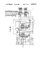
- FIGS. 1A and 1B are block diagrams of the apparatus of this invention and the apparatus associated with the present invention.
- FIG. 2a is a detailed circuit schematic of the saturation preamplifier in the patient module of FIG. 1.
- FIG. 2b is a detailed circuit schematic of the ECG preamplifier and input protection circuit in the patient module of FIG. 1.
- FIGS. 3A and 3B are detailed circuit schematics of the saturation analog front end circuit of FIG. 1.
- FIG. 4 is a detailed circuit schematic of the LED drive circuit of FIG. 1.
- FIG. 5 is a detailed circuit schematic of the ECG analog front end circuit of FIG. 1.
- FIGS. 6A and 6B are detailed circuit schematics of the analog to digital converter section of FIG. 1.
- FIGS. 7A, 7B, and 7C are detailed circuit schematics of the digital signal processing section of FIG. 1.
- FIG. 8 is a detailed circuit schematic of the external ECG circuitry of FIG. 1.
- FIGS. 9a, 9b, 9c, 9d, 9e and 9f are flow charts for the time domain ECG and optical signal processing of this invention.
- FIG. 10 is a flow chart for the frequency domain optical pulse processing of this invention.
- FIGS. 10a, 10b, 10c, 10d, and 10e are graphical representations of of the processing of the optical signals.
- the preferred embodiment of the present invention relates to the apparatus for processing the detected analog optical signal and the analog ECG signal and comprises portions of analog to digital conversion section ("ADC converter") 1000 and digital signal processing section ("DSP") 2000, including the software for driving microprocessor 2040, which processes the digitized optical signals and ECG signals to determine the oxygen saturation of hemoglobin in arterial blood.
- ADC converter analog to digital conversion section
- DSP digital signal processing section
- the apparatus for obtaining the detected analog optical signals and the analog ECG signals from the patient that is part of or is associated with the commercially available Nellcor N-200 Pulse Oximeter.
- Such apparatus include plethysmograph sensor 100 for detecting optical signals including periodic optical pulses, patient module 200 for interfacing plethysmograph sensor 100 and the conventional ECG electrodes with saturation analog front end circuit 300 and ECG analog front end circuit 400 respectively, saturation analog circuit 300 for processing the detected optical signals into separate red and infrared channels that can be digitized, and ECG anlog front end circuit 400 for processing the ECG signal so that it can be digitized.
- the N-200 oximeter also includes external ECG input circuit 500 for receiving an external ECG signal and processing the signal so that it is compatible with the N-200 processing techniques (as explained below), LED drive circuit 600 for strobing the red and infrared LEDs in plethysmograph sensor 100 at the proper intensity to obtain a detected optical signal that is acceptable for processing, and various regulated power supplies (not shown) for driving or biasing the associated circuits, as well as ADC 1000 and DSP 2000, from line current or storage batteries.
- external ECG input circuit 500 for receiving an external ECG signal and processing the signal so that it is compatible with the N-200 processing techniques (as explained below)
- LED drive circuit 600 for strobing the red and infrared LEDs in plethysmograph sensor 100 at the proper intensity to obtain a detected optical signal that is acceptable for processing
- various regulated power supplies (not shown) for driving or biasing the associated circuits, as well as ADC 1000 and DSP 2000, from line current or storage batteries.
- the invention requires three input signals, the two plethysmograph or detected optical signals (e.g., red and infrared) and the ECG signal of the patient. If analog signals are provided, they must be within or be adjusted by, for example, offset amplifiers, to be within the voltage input range for the ADC. In circumstances where the signals have been digitized already, they must be bit compatible with the digital signal processing devices, DSP.
- the plethysmograph signal is obtained in a conventional manner for a non-invasive oximeter, typically by illuminating the patients tissue with red and infrared light in an alternating fashion, in the manner described above for the N-100 oximeter.
- sensor circuit 100 has red LED 110 and infrared LED 120 connected in parallel, anode to cathode, so that the LED drive current alternately illuminates one LED and then the other LED.
- Circuit 100 also includes photodetector 130, preferably a photodiode, which detects the level of light transmitted through the patient's tissue, e.g., finger 140, as a single, analog optical signal containing both the red and infrared light plethysmographic, detected optical signal waveforms.
- photodetector 130 preferably a photodiode, which detects the level of light transmitted through the patient's tissue, e.g., finger 140, as a single, analog optical signal containing both the red and infrared light plethysmographic, detected optical signal waveforms.
- patient module 200 includes preamplifier 210 for preamplifying the analog detected optical signal of photodetector 130, ECG preamplifier 220 for preamplifying the analog ECG signal detected from the ECG electrodes that would be attached to the patient in a conventional manner, and protection circuitry 250 interposed between instrumentation amplifier 220 and inverter 230 and the three ECG signal leads, to prevent high voltage transients from damaging the ECG preamplifier electronics.
- Preamplifier 210 may be an operational amplifier configured as a current to voltage converter, biased by a positive voltage to extend the dynamic range of the system, thereby converting the photocurrent of photodiode 130 into a usable voltage signal.
- ECG preamplifier 220 is preferably a high quality instrumentation amplifier which amplifies the differential signal present on the two ECG signal electrodes.
- the common-mode signal present on the two signal electrodes is inverted by inverter 230 and returned to the patient by the third ECG lead, effectively nulling the common-mode signals.
- a biasing network on the two ECG signal leads is provided to aid in the detection of when an ECG electrode lead becomes disconnected from patient module 200 or the patient.
- Patient module 200 also includes leads for passing the LED drive voltages to LEDs 110 and 120.
- saturation analog front end circuit 300 receives the analog optical signal from patient module 200 and filters and processes the detected signal to provide separate red and infrared analog voltage signals corresponding to the detected red and infrared optical pulses.
- the voltage signal is passed through low pass filter 310 to remove unwanted high frequency components above, for example, 100 khz, AC coupled through capacitor 325 to remove the DC component, passed through high pass filter 320 to remove any unwanted low frequencies below, for example, 20 hertz, and passed through programmable gain stage 330 to amplify and optimize the signal level presented to synchronous detector 340.
- Synchronous detector 340 removes any common mode signals present and splits the time multiplexed optical signal into two channels, one representing the red voltage signals and the other representing the infrared voltage signals. Each signal is then passed through respective filter chains having two 2-pole 20 hertz low pass filters 350 and 360, and offset amplifier 370 and 380. The filtered voltage signals now contain the signal information corresponding to the red and infrared detected optical signals. Additionally, circuits for use in preventing overdriving the amplifiers in saturation circuit 300 may be applied, for example, level-sensing circuits 312 and 314 (located after low pass filter 310) for indicating unacceptable LED drive current, and level sensing circuit 315 (located after programmable gain amplifier 330) for indicating unacceptable input amplifier gain setting.
- ECG analog front end circuit 400 receives the preamplified ECG signal from patient module 200 and processes it for use with the present invention.
- the analog ECG signal is passed through 2-pole 40 hertz low pass filter 410 for removing unwanted frequencies above 40 hertz, and programmable notch filter 420 for removing unwanted line frequency components.
- circuitry may be provided to measure the line frequency and to select an appropriate clock frequency for the notch filter.
- the ECG signal is then passed through low pass filter 430, preferably configured to remove further unwanted components above about 40 hertz, and in particular any frequency components that may have been generated by notch filter 420.
- the ECG signal is passed through 2-pole 0.5 hertz high pass filter 440 to remove any low-frequency baseline shifts present in the original ECG signal, and then passed through offset amplifier 450 to add an offset voltage that the voltage is within the input signal specifications of the analog to digital converter device and the complete waveform will be properly digitized.
- the signal voltage is passed through absolute value circuit 480 to take the absolute value of the low pass filter output voltage and sends the value to comparator 490.
- Comparator 490 compares the absolute value voltage to a reference threshold or range and, when the absolute value voltage is not within the acceptable range, comparator 490 changes state which change is input to latch 495, to indicate this condition to, for example, the microprocessor.
- the Nellcor N-200 device also is equipped with external ECG circuit 500 for receiving the ECG signal of a stand alone ECG detector device and processing the ECG signal so that it can be used with the N-200 oximeter and the present invention.
- Circuit 500 receives the external analog ECG signal, passes it across capacitor 510 to remove any DC offset voltage and then passes the signal through peak detection circuit 530. A portion of the AC coupled signal also is passed through buffer amplifier 520 and input to comparator 570.
- the held peak voltage is used as the reference threshold voltage that is fed to the other input of comparator 570 so that subsequent QRS complexes in the ECG signal that rise above the threshhold generate a trigger signal that is transferred to DPS 2000 by an electrically isolated optical serial communication link comprising serial driving opto-isolator 580, electrically isolated optical link 590, and corresponding serial driving opto-isolator 2590 in DSP 2000.
- ADC 1000 provides the analog to digital conversions required by the N-200 oximeter.
- the aforementioned three voltage signals, the red detected optical signal, the infrared detected optical signal, and the ECG signal (preferably the ECG signal from patient module 200), are input to ADC 1000. These three signals are conventionally multiplexed and digitized by an expanded range 12-bit analog to digital conversion technique, yielding 16-bit resolution.
- the input signals are passed through multiplexor 1010 and buffer amplifier 1020.
- the converter stage includes offset amplifier 1030, programmable gain circuitry 1040 which allows a portion of the signal to be removed and the remainder to be further amplified for greater resolution, sample and hold circuit 1050, comparator 1060, and 12-bit digital to analog converter 1080.
- the buffered signal is passed through offset amplifier 1030 to add a DC bias to the signal wherein a portion of the signal is removed and the balance is amplified by being passed through programmable gain circuitry 1040 to improve the resolution.
- the amplified signal is then passed through sample and hold circuit 1050, the output of which is fed to one input of comparator 1060.
- the other input of comparator 1060 is the output of digital to analog (“DAC") converter 1080 so that when the inputs to comparator 1060 are the same, the analog voltage at the sample and hold circuit is given the corresponding digital word in DAC converter 1080 which is then stored in an appropriate memory device as the digitized data for the sample, and the next sample is sent to sample and hold circuit 1050 to be digitized.
- DAC digital to analog
- DAC 1080 also generates the sensor LED drive voltages, under the control of microprocessor 2040, using analog multiplexor 610, which separates the incoming analog signal into one of two channels for respectively driving the red and infrared LEDs, having respective sample and hold circuits 620 and 630, and LED driver circuit 640 for converting the respective analog voltage signals into the respective positive and negative bipolar current signals for driving LEDs 110 and 120.
- DSP 2000 controls all aspects of the signal processing operation including the signal input and output and intermediate processing.
- the apparatus includes 16-bit microprocessor 2040 and its associated support circuitry including data bus 10, random access memory (RAM) 2020, read only memory (ROM) 2030, a conventional LED display device 2010 (not shown in detail), system timing circuit 2050 for providing the necessary clock synchronizing and notch filter frequency signals.
- microprocessor 2040 is a model 8088 microprocessor, manufactured by Intel Corporation, Santa Clara, Calif. Alternate microprocessors may be used, such as any of model nos. 8086, 80186, and 80286, also made by Intel Corporation.
- FIGS. 9a, 9b, 9c, 9d, 9e, and 9f and software Appendix A the flowcharts for the software operation of the preferred embodiment are shown and described.
- Software appendix A is written in the standard programming language for Intel Model 8088 microprocessor devices.
- the N-200 oximeter incorporating the present invention is designed to determine the oxygen saturation in one or two modes, an unintegrated mode wherein the oxygen saturation determination is made on the basis of pulses detected in the optical pulse signal that are determined to be optical pulses in accordance with conventional pulse detection techniques, and in an ECG synchronization mode wherein the determination is based on the synchronized additive, composite optical signal information in accordance with the preferred embodiment of the present invention.
- the determination of saturation in the unintegrated mode may be based on the frequency domain analysis techniques in accordance with this invention with or without the ECG synchronization feature of the time domain analysis techniques.
- interrupt programs control the collection and digitization of incoming optical and ECG data.
- various software flags are raised which transfer operation to various routines that are called from the Main Loop Processing routine.
- Main Loop Processing calls the ECG routine at 3600, calls a routine that checks the LED levels at 3610 to make sure that there is enough and not too much light being transmitted, looks for the presence of new data at 3615, and if there is new data, calls the MUNCH routine at 3620, looks for processed pulse data at 3635 and passes such data to the Level3 routine that calculates saturation at 3640, and also runs various maintenance routines related to the oximeter functions which are not pertinant to the present invention, e.g., at 3625, 3630, 3645, 3650, 3655, and 3660 and are not discussed herein.
- the routines pertinent to the present invention are discussed here. Examples of similar and peripheral other routines may be found in the software appendix to application Ser. No. 742,720.
- the detected optical signal waveform is sampled at a rate of 57 samples per second.
- a software flag indicating the presence of data is set at 3615.
- This set flag calls a routine referred to as MUNCH at 3620, which processes each new digitized optical signal waveform sample.
- the MUNCH routine is called once per data point and determines pairs of maximum and minimum amplitudes in the detected signal data and presents the pairs to the Level3 routine.
- the Level3 routine evaluates the pair of maximum and minimum amplitudes determined by MUNCH, preferably utilizing conventional techniques for evaluating whether a detected pulse is acceptable for processing as an arterial pulse and performs the saturation calculation based on accepted pulses.
- the MUNCH routine first queries whether or not there is ECG synchronization. If there is ECG synchronization, then the MUNCH routine obtains from the SLIDER routine the enhanced pulse data on which the ECG synchronized saturation calculation will be made. If there is not synchronization, MUNCH obtains the sample stored in DATBUF on which the unintegrated saturation calculation will be made.
- the SLIDER routine processes each new digitized sample portion of detected optical signal containing the optical pulse to create and maintain the enhanced composite red and infrared optical pulse waveforms, synchronized with the occurrence of successive ECG R-wave events.
- the SLIDER routine first inquires whether there is an ECG signal at 3100. If there is not, then the routine aborts to exit at 3160 to main line operation. If there is an ECG signal, then the SLIDER routine continues and checks the validity of the optical signal at 3110. If the digitized sample in the buffer DATBUF for either of the red or infrared channels contains an invalid datapoint, the full content of the slider buffer (SLIDEBUF) is erased and the routine exited. The validity of the data is checked by looking for zeros placed in the buffer. Zeros are placed in the buffer when the signal level of the LEDs changes to permit the 20 Hz filters to settle, or if the signal exceeds the voltage limits of the processing electronics. This prevents processing of data known to be bad.
- the SLIDER routine queries whether or not the data should be skipped at 3120.
- the optical signal sampling and data collection and processing of the sampled data are asynchronous processes.
- the data buffer will have several unprocessed samples of data by the time the ECG R-wave event trigger occurs (described below).
- the R-wave event resets the slider buffer pointer to the begining of the slider buffer and marks the R-wave data sample in DATBUF.
- SLIDER will not process a data point if the slider buffer pointer is reset already to the beginning of the slider buffer and if the incoming data point was digitized in DATBUF before the data point marked by the R-wave event. Data in the DATBUF buffer prior to the R-wave event are to be skipped. If the data are to be skipped, SLIDER is exited.
- SLIDER calculates the updated value for the composite portion waveform sample as "slider -- data” using the following formula: ##EQU1## where "WEIGHT” is the aforementioned fractional weighting fraction; “new -- data” is the data point taken from the incoming sample in DATBUF, and “slider -- data” is the pre-existing data point in the composite waveform in the slider buffer (SLIDEBUF) before the new data point is added and becomes the updated data point after the computation.
- the computation is performed for each data point in DATBUF and any corresponding pre-existing data in the slider buffer.
- the occurrence of an R-wave event indicates the beginning of the heartbeat sample.
- SLIDER checks the slider buffer to see if there is any existing data at 3130. If there are data, then at 3150 SLIDER calculates the new value for the composite optical signal. If, however, the slider buffer is empty, then the WEIGHT value is assigned a numerial value of 1 at 3140, and subsequent new data points will be weighted 100% and the routine continues to calculate a new value for the composite optical signal at 3150 until the occurrence of the next R-wave event corresponding to the following heartbeat and portion of detected optical signal.
- the SLIDER routine also performs other housekeeping chores for the processing associated with the slider buffer.
- the slider buffer is given a specific length and is able to store about three seconds worth of data. If, for whatever reason, the microprocessor does not receive or recognize an R-wave for more than three seconds, the pointer of the slider buffer is set to point to the last location and does not get incremented beyond that location. Subsequently processed samples are each placed in the last location of the buffer until the next accepted R-wave occurs or a time-out condition occurs. Time-out occurs when no further R-wave events are accepted for a predetermined time of, e.g., five seconds. After time out has occurred, MUNCH is notified the ECG synchronization is lost so that saturation calculations will be based only on the optical signals in DATBUF in the unintegrated mode.
- SLIDER continuously compares the updated composite waveform in the slider buffer to the previous composite waveform. If there is a large discrepancy, for example, during electromechanical disassociation, SLIDER takes immediate action to disregard the slider buffer data.
- the content of the slider buffer is erased.
- the ECG -- BOX routine processes the ECG signal obtained through patient module 200 and analog ECG front end circuit to detect ECG R-wave events.
- the ECG signal is digitized every 5 msec and the digitized values are maintained in a circular buffer.
- the R-wave event is detected by observing the derivative of the ECG signal.
- the derivative is obtained at 3200 by application of the following algorithm: ##EQU2## where "ecg -- data[n]" is the digitized value for the ECG signal at sample location n and "abs[]" is the absolute value of the bracketed quantity.
- the largest magnitude spike in the derivative buffer marks the R-wave. Because the algorithm generates the absolute value of the derivative, the derivative buffer contains two spikes very close to each other, one for the positive-going portion and the other for the negative-going portion of the R-wave. After the first spike is recognized, a timer ecg -- block is set at 3250 to cause ECG -- BOX to ignore the second spike.
- ECG threshold is a value that is set at about 75% of the previous maximum derivative value. If the derivative is greater than the threshold, ECG -- BOX starts the ecg -- block timer by setting ecg -- block equal to true at 3250, and it replaces the maximum derivative value with the current derivative value at 3260, and calls the R-WAVE CHECKING routine at 3270. After the R-WAVE CHECKING routine is completed (as discussed below), ECG -- BOX is exited at 3280.
- ECG -- BOX is exited at 3280. Once the ecg -- block timer is activated, ECG -- BOX will continue to calculate the derivative and compare the derivative to the prior maximum derivative value at 3220. If the calculated derivative is greater, then the maximum derivative value is set equal to the current derivative -- ecg -- data[n] at 3230 and the routine is exited. Otherwise the routine is exited.
- the R-WAVE CHECKING routine receives the detected R-wave event at 3500 and checks the elapsed time since the last R-wave at 3510. If the elapsed time is less than the minimum internal time limit, preferably set at about 200 msec, the R-wave event is marked as a false R-wave event at 3520. If the elapsed time is greater than the minimum limit, then the routine starts a phase-delay timer/counter at 3530.
- the purpose of the phase-delay counter is to ensure that the optical data is placed into the beginning of the slider buffer after the optical signal minimum from the preceding pulse, but before the signal maximum of the next pulse.
- the preferred phase-delay period is 40 msec, based on the results of experimentation, and corresponds to the opening of the time window. It may be desirable to have a phase delay period that can be adjusted to accommodate varying optical signal detection conditions for different patients.
- the Nellcor N-200 device is equipped with an external ECG input circuit as described above.
- the main line operating system controlling the operation of the N-200 device receives an interrupt when the external circuit 500 detects an R-wave.
- a message is sent across isolated optical data transmission path 580-590-2590 (FIG. 1) to microprocessor 2040.
- the microprocessor indicates to the ECG processing routines that an externally detected R-wave event has occurred, and the R-wave event is passed to the R-WAVE CHECKING routine.
- the external ECG analog circuit 500 thus performs the same function as the ECG -- BOX routine, i.e., determination of an R-wave event followed by the R-WAVE CHECKING routine.
- the ECG -- BOX routine is given priority over external ECG circuit 500 in passing signals to R-WAVE CHECKING.
- the ECG routine provides for ECG synchronization, the initialization for slider buffer use, and various other tasks associated with ECG enhancement of the detected optical signal.
- the ECG routine is entered from the Main Loop Processing system (FIG. 9f, at 3600). Its first task is to maintain the ECG related counters/timers, such as ecg -- block and phase-delay, at 3300. Next, at 3310, it checks whether or not the ECG leads from patient module 200 are present, and if not, it checks at 3320 for the presence of an external R-wave event trigger from external ECG circuit 500. If no R-wave event is detected, then the ECG routine is exited at 3370.
- the ECG routine is exited at 3370.
- the main line processing system is receiving R-wave events, either from external circuit 500 or from patient module 200 and ECG -- BOX. Regardless of the source of the R-wave event, the subsequent processing of the R-wave event is the same.
- ECG -- LV3 runs through a similar patient module 200 lead checking at 3410 or external circuit 500 trigger at 3420 as the ECG routine and if no R-wave event has occurred the routine is exited at 3480. If an R-wave event is detected, it is first checked at 3425 to determine whether or not it is a new R-wave event, and if it is not, the ECG -- LV3 routine is exited. If it is a new R-wave event, 3430 uses the false R-wave flag (set by the R-WAVE CHECKING routine) to determine whether or not it was a true or false R-wave event. False R-waves will cause the routine to be exited at this point.
- the ECG-LV3 routine builds up a history of R-wave events based on the R-wave to R-wave interval at 3435.
- the criteria for accepting an R-wave includes the R--R period and the amplitude of the R-wave.
- the R-wave event is a uniform pulse resulting from a comparison of the R-wave amplitude to a determined threshold signal.
- the ECG -- LV3 routine After computing the R--R interval (or R--delta) and history, the ECG -- LV3 routine checks to see if the ECG is synchronized at 3440.
- the ECG is synchronized after receiving the predetermined number, preferably five, acceptable R-wave triggers. For example, the ECG -- synch counter is initialized at five.
- the routine tests the ECG -- synch counter 3440 so that if it is greater than zero, the ECG is determined to be not synched, and then the ECG -- synch counter is decreased by one at 3455.
- ECG -- synch counter is at zero at 3440, indicating that the required prior five acceptable R-wave events have successively occurred, then it is determined that there is ECG synchronization and the device will proceed through MUNCH to calculate oxygen saturation based on the enhanced composite slider buffer calculations.
- any R-wave event is checked again at 3450 against the history and R--R interval, if any, to determine whether there is an error in synchronization. If there is an error, the ECG -- LV3 routine is exited. If there is no synchronization error, a routine is called at 3460 to compute the maximum length of time after which data in the slider buffer (SLIDEBUF) is disregarded.
- the ECG -- LV3 routine also calculates the maximum length of the slider buffer based on the heart rate, which length is preferably 3 seconds or 2.5 times the determined R--R interval, whichever is the smaller.
- the ECG -- LV3 routine also maintains the slider pointers and counters, resetting them or clearing them as necessary, resets the ecg timeout and bad R-wave counter, computes the displays heart rate based on the R--R interval at 3465, updates the history buffers and sets the trigger for the MUNCH routine to calculate pulse data for determining oxygen saturation based on the updated slider buffer data at 3470, sets and computes windows for selecting the portion of detected optical signal to be processed for each heartbeat, based on the history and the most recent data at 3475.
- the windows are set to open by the R-WAVE CHECKING routine phase-delay counter/timer 40 ms after the R-wave occurs and before the maximum optical pulse wave has occurred at the detection site, and set to close by the MUNCH routine after a maximum and minimum pair has been found.
- the program Upon exiting ECG -- LV3, the program returns to the ECG routine and checks the threshold of the derivative buffer of ECG -- BOX. If the maximum derivative value is changed substantially, which indicates that the R-wave slope is changing, then the threshold is adjusted.
- the routine begins at 4000 with the acquisition of 512 data points for each of the digitized red and infrared optical signals, which are shown graphically at FIG. 10a.
- the "D.C.” component is formed by summing all of the data points, and the "D.C.” component is then removed from the complex data set by subtraction at 4030, which is graphically shown at FIG. 10b.
- the resulting data is then decimated in time to 64 samples at 4040, which is illustrated in FIG. 10c, and the time decimated data is then processed by the Hamming Window function at 4050, which result is illustrated in FIG. 10d.
- the Fourier Transform is taken at 4060.
- the spectral components of the transform are shown in FIG. 10e.
- the Fourier Transforms of the red and infrared components are then calculated at 4070 in accordance with the aforementioned equations, and at 4080 the maximum value at the fundamental heart rate and the minimum value at the zero frequency are determined for each of the red and infrared transforms.
- the saturation ratio R is calculated as: ##EQU3##
- the minimum values for the red and infrared waveforms are taken from the respective real and imaginary components of the "D.C.” component.
- the pulse data is declared ready and saturation is calculated in accordance with the foregoing saturation formula. With each occurrence of the heartbeat, new data is acquired, the 512 data point set is updated and the routine operates to determine the saturation ratio R.
- the blood constituent measured is the oxygen saturation of the blood of a patient.
- the calculation of the oxygen saturation is made based on the ratio of the pulse seen by the red light compared to the pulse seen by the infrared light in accordance with the following equation: ##EQU4## wherein BO1 is the extinction coefficient for oxygenated hemoglobin at light wavelength 1 (Infrared)
- BO2 is the extinction coefficient for oxygenated hemoglobin at light wavelength 2 (red)
- BR1 is the extinction coefficient for reduced hemoglobin at light wavelength 1
- BR2 is the extinction coefficient for reduced hemoglobin at light wavelength 2
- light wavelength 1 is infrared light
- light wavelength 2 is red light
- I min2 is the minimum light transmitted at light wavelength 2
- I max1 is the maximum light transmitted at light wavelength 1
- I min1 is the minimum light transmitted at light wavelength 1
- the various extinction coefficients are determinable by empirical study as is well known to those of skill in the art.
- the natural log of the ratios may be calculated by use of the Taylor expansion series for the natural log.
Abstract
Description
F{Re[f(t)]}=1/2{F(s)+F*(-s)}.
F{Im[f(t)]}=1/2{F(s)-F*(-s)}.
__________________________________________________________________________
Circuit Tables
REF #
    CHIP
        MFR PART #
                  Manufacturer
                             DESCRIPTION OF CHIP
__________________________________________________________________________
FIG. 2
210 U2  LF442     NATIONAL   DUAL LOW POWER OP AMP
                  SEMICONDUCTOR
220 U1  INA101HP  BURR BROWN INSTRUMENTATION AMP
230 U2  LF442     NATIONAL   DUAL LOW POWER OP AMP
                  SEMICONDUCTOR
FIG. 3
312 U27 LF444     NATIONAL   QUAD JFET OP AMP
                  SEMICONDUCTOR
312 U28 LP365N    NATIONAL   QUAD VOLTAGE COMPARATOR
                  SEMICONDUCTOR
310 U27 LF444     NATIONAL   QUAD JFET OP AMP
                  SEMICONDUCTOR
320 U27 LF444     NATIONAL   QUAD JFET OP AMP
                  SEMICONDUCTOR
330 U44 MP7524LN  MICROPOWER 8-BIT DAC
330 U32 LF444     NATIONAL   QUAD JFET OP AMP
                  SEMICONDUCTOR
330 U32 LF444     NATIONAL   QUAD JFET OP AMP
                  SEMICONDUCTOR
315 U20 LP365N    NATIONAL   QUAD VOLTAGE COMPARATOR
                  SEMICONDUCTOR
340 U32 LF444     NATIONAL   QUAD JFET OP AMP
                  SEMICONDUCTOR
340 U14 DG243CJ   SILICONIX  ANALOG SWlTCH
                  INCORPORATED
340 U7  LF444     NATIONAL   QUAD JFET OP AMP
                  SEMICONDUCTOR
340 U13 LF444     NATIONAL   QUAD JFET OP AMP
                  SEMICONDUCTOR
350 U7  LF444     NATIONAL   QUAD JFET OP AMP
                  SEMICONDUCTOR
360 U13 LF444     NATIONAL   QUAD JFET OP AMP
                  SEMICONDUCTOR
370 U7  LF444     NATIONAL   QUAD JFET OP AMP
                  SEMICONDUCTOR
380 U13 LF444     NATIONAL   QUAD JFET OP AMP
                  SEMICONDUCTOR
340 U19 DG211CJ   SILICONIX  CMOS ANALOG SWITCH
                  INCORPORATED
FIG. 4
640 U19 DG211CJ   SILICONIX  CMOS ANALOG SWITCH
                  INCORPORATED
640 U32 LF444     NATIONAL   QUAD JFET OP AMP
                  SEMICONDUCTOR
FIG. 5
410 U12 LF444     NATIONAL   QUAD JFET OP AMP
                  SEMICONDUCTOR
420 U6  LTC1059CN LINEAR     SWITCHED CAPACITOR FILTER
                  TECHNOLOGY
430 U12 LF444     NATIONAL   QUAD JFET OP AMP
                  SEMICONDUCTOR
440 U12 LF444     NATIONAL   QUAD JFET OP AMP
                  SEMICONDUCTOR
440 U19 DG211CJ   SILICONIX  CMOS ANALOG SWlTCH
                  INCORPORATED
450 U12 LF444     NATIONAL   QUAD JFET OP AMP
                  SEMICONDUCTOR
480 U5  LF444     NATIONAL   QUAD JFET OP AMP
                  SEMICONDUCTOR
490 U4  LM393N    NATIONAL   VOLTAGE COMPARATOR
                  SEMICONDUCTOR
495 U10 74HC00    TEXAS      HIGH SPEED CMOS
                  INSTRUMENTS
495 U3  74HC74    TEXAS      HIGH SPEED CMOS
                  INSTRUMENTS
FIG. 6
1010
    U24 DG528CK   SILICONIX  OCTAL ANALOG SWITCH
                  INCORPORATED
1020
    U25 LF444     NATIONAL   QUAD JFET OP AMP
                  SEMICONDUCTOR
1030
    U25 LF444     NATIONAL   QUAD JFET OP AMP
                  SEMICONDUCTOR
1040
    U38 AD7524LN  ANALOG DEVICES
                             DAC
1040
    U42 74HC374   TEXAS      HIGH SPEED CMOS
                  INSTRUMENTS
1040
    U37 LF442N    NATIONAL   LOW POWER OP AMP
                  SEMICONDUCTOR
1050
    U36 LF398N    NATIONAL   SAMPLE & H0LD OP AMP
                  SEMICONDUCTOR
1060
    U29 LM211P    TEXAS      LOW OFFSET VOLTAGE COMPARATOR
                  INSTRUMENTS
1080
    U43 AD7548KN  ANALOG DEVICES
                             CMOS 12-BIT DAC
1080
    U31 LF411ACN  NATIONAL   LOW OFFSET OP AMP
                  SEMICONDUCTOR
1080
    U25 LF444     NATIONAL   QUAD JFET OP AMP
                  SEMICONDUCTOR
610 U18 DG528CK   SILICONIX  OCTAL ANALOG SWITCH
                  INCORPORATED
620 U11 LF444     NATIONAL   QUAD JFET OP AMP
                  SEMICONDUCTOR
630 U11 LF444     NATIONAL   QUAD JFET OP AMP
                  SEMICONDUCTOR
FIG. 7
    U2  82C84A-2  NEC        CMOS 8 MHZ CLOCK GENERATOR
    U1  74HC74    TEXAS      HIGH SPEED CMOS
                  INSTRUMENTS
    U1  7HC74     TEXAS      HIGH SPEED CMOS
                  INSTRUMENTS
2040
    U8  MSM80C88RS-2
                  OKI ELECTRIC
                             CPU 8MHZ, 125ns
    U3  74HC74    TEXAS      HIGH SPEED CMOS
                  INSTRUMENTS
    U33 74HC374   TEXAS      HIGH SPEED CMOS
                  INSTRUMENTS
    U9  74HC04    TEXAS      HIGH SPEED CMOS
                  INSTRUMENTS
    U3  74HC74    TEXAS      HIGH SPEED CMOS
                  INSTRUMENTS
    U9  74HC04    TEXAS      HIGH SPEED CMOS
                  INSTRUMENTS
    U19 74HC00    TEXAS      HIGH SPEED CMOS
                  INSTRUMENTS
    U9  74HC04    TEXAS      HIGH SPEED CMOS
                  INSTRUMENTS
2030
    U21 MBM27C512-25
                  FUJITSU LIMITED
                             CMOS 64K × 8 ROM
2020
    U15 DS1242    DALLAS     CMOS 32K × 8 RAM
                  SEMICONDUCTOR
    U23 74HC138   TEXAS      HIGH SPEED CMOS
                  INSTRUMENTS
    U17 74HC138   TEXAS      HIGH SPEED CMOS
                  INSTRUMENTS
    U19 74HC00    TEXAS      HIGH SPEED CMOS
                  INSTRUMENTS
    U19 74HC00    TEXAS      HIGH SPEED CMOS
                  INSTRUMENTS
    U16 82C51A    OKI ELECTRIC
                             CMOS UART
    U22 MSM82C59A-2RS
                  OKI ELECTRlC
                             CMOS INTERRUPT CONTROLLER
2050
    U34 MSM82C53-2
                  OKI ELECTRIC
                             CMOS TRIPLE TIMER
2050
    U38 MSM82C53-2
                  OKI ELECTRIC
                             CMOS TRIPE TIMER
2050
    U9  74HC04    TEXAS      HIGH SPEED CMOS
                  INSTRUMENTS
2050
    U39 74HC393   TEXAS      HIGH SPEED CMOS
                  INSTRUMENTS
2050
    U35 D273A     INTEL      4096 × 8 ROM
                  CORPORATION
2050
    U40 74HC374   TEXAS      HIGH SPEED CMOS
                  INSTRUMENTS
2050
    U28 74HC374   TEXAS      HIGH SPED CMOS
                  INSTRUMENTS
FIG. 8
520 U3  LF444     NATIONAL   QUAD JFET OP AMP
                  SEMICONDUCTOR
530 U2  LF444     NATIONAL   QUAD JFET OP AMP
                  SEMICONDUCTOR
530 U3  LF444     NATIONAL   QUAD JFET OP AMP
                  SEMICONDUCTOR
570 U7  LM311N    NATIONAL   VOLTAGE COMPARATOR W/STROBE
                  SEMICONDUCTOR
__________________________________________________________________________
 ##SPC1##
Claims (37)
Priority Applications (1)
| Application Number | Priority Date | Filing Date | Title |
|---|---|---|---|
| US07/334,694 US4934372A (en) | 1985-04-01 | 1989-04-05 | Method and apparatus for detecting optical pulses |
Applications Claiming Priority (3)
| Application Number | Priority Date | Filing Date | Title |
|---|---|---|---|
| US71852585A | 1985-04-01 | 1985-04-01 | |
| US07/175,152 US4911167A (en) | 1985-06-07 | 1988-03-30 | Method and apparatus for detecting optical pulses |
| US07/334,694 US4934372A (en) | 1985-04-01 | 1989-04-05 | Method and apparatus for detecting optical pulses |
Related Parent Applications (1)
| Application Number | Title | Priority Date | Filing Date |
|---|---|---|---|
| US07/175,152 Division US4911167A (en) | 1985-04-01 | 1988-03-30 | Method and apparatus for detecting optical pulses |
Publications (1)
| Publication Number | Publication Date |
|---|---|
| US4934372A true US4934372A (en) | 1990-06-19 |
Family
ID=27390500
Family Applications (1)
| Application Number | Title | Priority Date | Filing Date |
|---|---|---|---|
| US07/334,694 Expired - Lifetime US4934372A (en) | 1985-04-01 | 1989-04-05 | Method and apparatus for detecting optical pulses |
Country Status (1)
| Country | Link |
|---|---|
| US (1) | US4934372A (en) |
Cited By (188)
| Publication number | Priority date | Publication date | Assignee | Title |
|---|---|---|---|---|
| US5094239A (en) * | 1989-10-05 | 1992-03-10 | Colin Electronics Co., Ltd. | Composite signal implementation for acquiring oximetry signals |
| US5099841A (en) * | 1989-02-06 | 1992-03-31 | Instrumentarium Corporation | Measurement of the composition of blood |
| US5170796A (en) * | 1990-03-01 | 1992-12-15 | Colin Electronics Co., Ltd. | Pulse wave detecting apparatus |
| US5213099A (en) * | 1991-09-30 | 1993-05-25 | The United States Of America As Represented By The Secretary Of The Air Force | Ear canal pulse/oxygen saturation measuring device |
| US5246002A (en) * | 1992-02-11 | 1993-09-21 | Physio-Control Corporation | Noise insensitive pulse transmittance oximeter |
| US5291886A (en) * | 1990-11-27 | 1994-03-08 | Kowa Company Ltd. | Apparatus for measuring blood flow |
| US5313941A (en) * | 1993-01-28 | 1994-05-24 | Braig James R | Noninvasive pulsed infrared spectrophotometer |
| US5396893A (en) * | 1990-02-16 | 1995-03-14 | Oberg; Ake P. | Method and apparatus for analyzing heart and respiratory frequencies photoplethysmographically |
| US5499190A (en) * | 1992-01-16 | 1996-03-12 | Hamamatsu Photonics K.K. | System for measuring timing relationship between two signals |
| US5505199A (en) * | 1994-12-01 | 1996-04-09 | Kim; Bill H. | Sudden infant death syndrome monitor |
| US5515847A (en) * | 1993-01-28 | 1996-05-14 | Optiscan, Inc. | Self-emission noninvasive infrared spectrophotometer |
| US5575284A (en) * | 1994-04-01 | 1996-11-19 | University Of South Florida | Portable pulse oximeter |
| US5830137A (en) * | 1996-11-18 | 1998-11-03 | University Of South Florida | Green light pulse oximeter |
| US5921921A (en) * | 1996-12-18 | 1999-07-13 | Nellcor Puritan-Bennett | Pulse oximeter with sigma-delta converter |
| US5961450A (en) * | 1993-12-17 | 1999-10-05 | Nellcor Puritan Bennett Incorporated | Medical sensor with amplitude independent output |
| US5978691A (en) * | 1996-07-19 | 1999-11-02 | Mills; Alexander Knight | Device and method for noninvasive continuous determination of blood gases, pH, hemoglobin level, and oxygen content |
| US6002952A (en) * | 1997-04-14 | 1999-12-14 | Masimo Corporation | Signal processing apparatus and method |
| US6022321A (en) * | 1993-09-28 | 2000-02-08 | Seiko Epson Corporation | Blood pulse wave detecting apparatus and motion intensity measuring apparatus |
| US6025597A (en) * | 1995-10-17 | 2000-02-15 | Optiscan Biomedical Corporation | Non-invasive infrared absorption spectrometer for measuring glucose or other constituents in a human or other body |
| US6036642A (en) * | 1991-03-07 | 2000-03-14 | Masimo Corporation | Signal processing apparatus and method |
| US6064898A (en) * | 1998-09-21 | 2000-05-16 | Essential Medical Devices | Non-invasive blood component analyzer |
| US6072180A (en) * | 1995-10-17 | 2000-06-06 | Optiscan Biomedical Corporation | Non-invasive infrared absorption spectrometer for the generation and capture of thermal gradient spectra from living tissue |
| US6094592A (en) * | 1998-05-26 | 2000-07-25 | Nellcor Puritan Bennett, Inc. | Methods and apparatus for estimating a physiological parameter using transforms |
| US6104938A (en) * | 1996-06-12 | 2000-08-15 | Instrumentarium Oy | Procedure, apparatus and detector for the determination of fractional oxygen saturation |
| WO2001082786A2 (en) * | 2000-05-03 | 2001-11-08 | Flock Stephen T | Optical imaging of subsurface anatomical structures and biomolecules |
| US20020128544A1 (en) * | 1991-03-07 | 2002-09-12 | Diab Mohamed K. | Signal processing apparatus |
| US20020137994A1 (en) * | 1995-08-07 | 2002-09-26 | Nellcor Incorporated, A Delaware Corporation | Method and apparatus for estimating physiological parameters using model-based adaptive filtering |
| US6480729B2 (en) | 2000-04-28 | 2002-11-12 | Alexander K. Mills | Method for determining blood constituents |
| US6594511B2 (en) | 2000-03-29 | 2003-07-15 | Robert T. Stone | Method and apparatus for determining physiological characteristics |
| US6658277B2 (en) | 2001-09-13 | 2003-12-02 | Imagyn Medical Technologies, Inc. | Signal processing method and device for signal-to-noise improvement |
| US6694157B1 (en) | 1998-02-10 | 2004-02-17 | Daedalus I , L.L.C. | Method and apparatus for determination of pH pCO2, hemoglobin, and hemoglobin oxygen saturation |
| USRE38476E1 (en) | 1991-03-07 | 2004-03-30 | Masimo Corporation | Signal processing apparatus |
| US6801799B2 (en) | 2000-10-05 | 2004-10-05 | Cybro Medical, Ltd. | Pulse oximeter and method of operation |
| US20040236196A1 (en) * | 1991-03-07 | 2004-11-25 | Diab Mohamed K. | Signal processing apparatus |
| US20050049471A1 (en) * | 2003-08-25 | 2005-03-03 | Aceti John Gregory | Pulse oximetry methods and apparatus for use within an auditory canal |
| US20050059870A1 (en) * | 2003-08-25 | 2005-03-17 | Aceti John Gregory | Processing methods and apparatus for monitoring physiological parameters using physiological characteristics present within an auditory canal |
| US20050187452A1 (en) * | 2004-02-25 | 2005-08-25 | Nellcor Puritan Bennett Inc. | Oximeter cross-talk reduction |
| US20050187447A1 (en) * | 2004-02-25 | 2005-08-25 | Nellcor Puritan Bennett Inc. | Switch-mode oximeter LED drive with a single inductor |
| US20050187453A1 (en) * | 2004-02-25 | 2005-08-25 | Nellcor Puritan Bennett Inc. | Delta-sigma modulator for outputting analog representation of physiological signal |
| US20050187448A1 (en) * | 2004-02-25 | 2005-08-25 | Nellcor Puritan Bennett Inc. | Oximeter ambient light cancellation |
| US20050187450A1 (en) * | 2004-02-25 | 2005-08-25 | Nellcor Puritan Bennett Inc. | LED forward voltage estimation in pulse oximeter |
| US20050184895A1 (en) * | 2004-02-25 | 2005-08-25 | Nellcor Puritan Bennett Inc. | Multi-bit ADC with sigma-delta modulation |
| US20050187446A1 (en) * | 2004-02-25 | 2005-08-25 | Nellcor Puritan Bennett | Techniques for detecting heart pulses and reducing power consumption in sensors |
| US20050240087A1 (en) * | 2003-11-18 | 2005-10-27 | Vivometrics Inc. | Method and system for processing data from ambulatory physiological monitoring |
| US20060036183A1 (en) * | 2002-03-26 | 2006-02-16 | Vivometrics Inc. | Method and system for extracting cardiac parameters from plethysmographic signals |
| US20060200015A1 (en) * | 2005-03-03 | 2006-09-07 | Nellcor Puritan Bennett Incorporated | Method for enhancing pulse oximetry calculations in the presence of correlated artifacts |
| WO2006099988A1 (en) * | 2005-03-21 | 2006-09-28 | Flore, Ingo | Mobile diagnosis device |
| US7184809B1 (en) | 2005-11-08 | 2007-02-27 | Woolsthorpe Technologies, Llc | Pulse amplitude indexing method and apparatus |
| US20070049811A1 (en) * | 2005-08-24 | 2007-03-01 | Nihon Kohden Corporation | Apparatus and method for measuring oxygen saturation in blood |
| US7194293B2 (en) | 2004-03-08 | 2007-03-20 | Nellcor Puritan Bennett Incorporated | Selection of ensemble averaging weights for a pulse oximeter based on signal quality metrics |
| US7215987B1 (en) | 2005-11-08 | 2007-05-08 | Woolsthorpe Technologies | Method and apparatus for processing signals reflecting physiological characteristics |
| US20070179734A1 (en) * | 2005-09-28 | 2007-08-02 | Chmiel Alan J | Transfer function control for biometric monitoring system and related method |
| US20070270671A1 (en) * | 2006-04-10 | 2007-11-22 | Vivometrics, Inc. | Physiological signal processing devices and associated processing methods |
| US20080027341A1 (en) * | 2002-03-26 | 2008-01-31 | Marvin Sackner | Method and system for extracting cardiac parameters from plethysmographic signals |
| US20080045815A1 (en) * | 2006-06-20 | 2008-02-21 | Derchak P A | Automatic and ambulatory monitoring of congestive heart failure patients |
| US7373192B2 (en) | 2004-02-25 | 2008-05-13 | Nellcor Puritan Bennett Inc. | Oximeter red and IR zero calibration control |
| US7376453B1 (en) | 1993-10-06 | 2008-05-20 | Masimo Corporation | Signal processing apparatus |
| US7377794B2 (en) | 2005-03-01 | 2008-05-27 | Masimo Corporation | Multiple wavelength sensor interconnect |
| US20080167541A1 (en) * | 2007-01-09 | 2008-07-10 | Panu Takala | Interference Suppression in Spectral Plethysmography |
| US20080183096A1 (en) * | 2007-01-25 | 2008-07-31 | David Snyder | Systems and Methods for Identifying a Contra-ictal Condition in a Subject |
| US20080221401A1 (en) * | 2006-10-27 | 2008-09-11 | Derchak P Alexander | Identification of emotional states using physiological responses |
| US7477924B2 (en) | 2006-05-02 | 2009-01-13 | Nellcor Puritan Bennett Llc | Medical sensor and technique for using the same |
| US7483731B2 (en) | 2005-09-30 | 2009-01-27 | Nellcor Puritan Bennett Llc | Medical sensor and technique for using the same |
| US7486979B2 (en) | 2005-09-30 | 2009-02-03 | Nellcor Puritan Bennett Llc | Optically aligned pulse oximetry sensor and technique for using the same |
| US20090062682A1 (en) * | 2007-07-27 | 2009-03-05 | Michael Bland | Patient Advisory Device |
| US20090069685A1 (en) * | 2007-09-12 | 2009-03-12 | Canon Kabushiki Kaisha | Measurement apparatus |
| US7522948B2 (en) | 2006-05-02 | 2009-04-21 | Nellcor Puritan Bennett Llc | Medical sensor and technique for using the same |
| US20090163775A1 (en) * | 2007-12-21 | 2009-06-25 | Barrett Bruce J | Physiological sensor |
| US7555327B2 (en) | 2005-09-30 | 2009-06-30 | Nellcor Puritan Bennett Llc | Folding medical sensor and technique for using the same |
| US20090171176A1 (en) * | 2007-12-28 | 2009-07-02 | Nellcor Puritan Bennett Llc | Snapshot Sensor |
| US7574244B2 (en) | 2005-08-08 | 2009-08-11 | Nellcor Puritan Bennett Llc | Compliant diaphragm medical sensor and technique for using the same |
| US7574245B2 (en) | 2006-09-27 | 2009-08-11 | Nellcor Puritan Bennett Llc | Flexible medical sensor enclosure |
| US7590439B2 (en) | 2005-08-08 | 2009-09-15 | Nellcor Puritan Bennett Llc | Bi-stable medical sensor and technique for using the same |
| US20090326356A1 (en) * | 2008-06-30 | 2009-12-31 | Medtronic, Inc. | Cardiac signal sensor control |
| US20090326346A1 (en) * | 2008-06-30 | 2009-12-31 | Medtronic, Inc. | Optical perfusion sensor detector |
| US20090326350A1 (en) * | 2008-06-30 | 2009-12-31 | Medtronic, Inc. | Tissue perfusion sensor control |
| US7650177B2 (en) | 2005-09-29 | 2010-01-19 | Nellcor Puritan Bennett Llc | Medical sensor for reducing motion artifacts and technique for using the same |
| US20100016693A1 (en) * | 2008-07-15 | 2010-01-21 | Nellcor Puritan Bennett Ireland | Systems And Methods For Identifying Pulse Rates |
| US7657295B2 (en) | 2005-08-08 | 2010-02-02 | Nellcor Puritan Bennett Llc | Medical sensor and technique for using the same |
| US20100030088A1 (en) * | 2008-07-30 | 2010-02-04 | Medtronic, Inc. | Physiological parameter monitoring with minimization of motion artifacts |
| US7658652B2 (en) | 2006-09-29 | 2010-02-09 | Nellcor Puritan Bennett Llc | Device and method for reducing crosstalk |
| US7676253B2 (en) | 2005-09-29 | 2010-03-09 | Nellcor Puritan Bennett Llc | Medical sensor and technique for using the same |
| US7680522B2 (en) | 2006-09-29 | 2010-03-16 | Nellcor Puritan Bennett Llc | Method and apparatus for detecting misapplied sensors |
| US7684842B2 (en) | 2006-09-29 | 2010-03-23 | Nellcor Puritan Bennett Llc | System and method for preventing sensor misuse |
| US7689259B2 (en) | 2000-04-17 | 2010-03-30 | Nellcor Puritan Bennett Llc | Pulse oximeter sensor with piece-wise function |
| US20100081902A1 (en) * | 2008-09-30 | 2010-04-01 | Nellcor Puritan Bennett Llc | Medical Sensor and Technique for Using the Same |
| US20100087720A1 (en) * | 2008-10-02 | 2010-04-08 | Nellcor Puritan Bennett Ireland, Mervue | Extraction Of Physiological Measurements From A Photoplethysmograph (PPG) Signal |
| US7720516B2 (en) | 1996-10-10 | 2010-05-18 | Nellcor Puritan Bennett Llc | Motion compatible sensor for non-invasive optical blood analysis |
| US20100168604A1 (en) * | 2008-12-29 | 2010-07-01 | Javier Ramon Echauz | Processing for Multi-Channel Signals |
| US7796403B2 (en) | 2006-09-28 | 2010-09-14 | Nellcor Puritan Bennett Llc | Means for mechanical registration and mechanical-electrical coupling of a faraday shield to a photodetector and an electrical circuit |
| USD626561S1 (en) | 2008-06-30 | 2010-11-02 | Nellcor Puritan Bennett Llc | Circular satseconds indicator and triangular saturation pattern detection indicator for a patient monitor display panel |
| USD626562S1 (en) | 2008-06-30 | 2010-11-02 | Nellcor Puritan Bennett Llc | Triangular saturation pattern detection indicator for a patient monitor display panel |
| US20100331640A1 (en) * | 2009-06-26 | 2010-12-30 | Nellcor Puritan Bennett Llc | Use of photodetector array to improve efficiency and accuracy of an optical medical sensor |
| US20110004069A1 (en) * | 2009-07-06 | 2011-01-06 | Nellcor Puritan Bennett Ireland | Systems And Methods For Processing Physiological Signals In Wavelet Space |
| US7869849B2 (en) | 2006-09-26 | 2011-01-11 | Nellcor Puritan Bennett Llc | Opaque, electrically nonconductive region on a medical sensor |
| US7880884B2 (en) | 2008-06-30 | 2011-02-01 | Nellcor Puritan Bennett Llc | System and method for coating and shielding electronic sensor components |
| US7881762B2 (en) | 2005-09-30 | 2011-02-01 | Nellcor Puritan Bennett Llc | Clip-style medical sensor and technique for using the same |
| US7884933B1 (en) | 2010-05-05 | 2011-02-08 | Revolutionary Business Concepts, Inc. | Apparatus and method for determining analyte concentrations |
| US7890153B2 (en) | 2006-09-28 | 2011-02-15 | Nellcor Puritan Bennett Llc | System and method for mitigating interference in pulse oximetry |
| US7887345B2 (en) | 2008-06-30 | 2011-02-15 | Nellcor Puritan Bennett Llc | Single use connector for pulse oximetry sensors |
| US7894869B2 (en) | 2007-03-09 | 2011-02-22 | Nellcor Puritan Bennett Llc | Multiple configuration medical sensor and technique for using the same |
| US7899510B2 (en) | 2005-09-29 | 2011-03-01 | Nellcor Puritan Bennett Llc | Medical sensor and technique for using the same |
| US20110071378A1 (en) * | 2009-09-24 | 2011-03-24 | Nellcor Puritan Bennett Llc | Signal Processing Warping Technique |
| EP2319398A1 (en) * | 1998-06-03 | 2011-05-11 | Masimo Corporation | Stereo pulse oximeter |
| US20110213222A1 (en) * | 2007-01-25 | 2011-09-01 | Leyde Kent W | Communication Error Alerting in an Epilepsy Monitoring System |
| US8019400B2 (en) | 1994-10-07 | 2011-09-13 | Masimo Corporation | Signal processing apparatus |
| US8033996B2 (en) | 2005-07-26 | 2011-10-11 | Adidas Ag | Computer interfaces including physiologically guided avatars |
| US8062221B2 (en) | 2005-09-30 | 2011-11-22 | Nellcor Puritan Bennett Llc | Sensor for tissue gas detection and technique for using the same |
| US8068891B2 (en) | 2006-09-29 | 2011-11-29 | Nellcor Puritan Bennett Llc | Symmetric LED array for pulse oximetry |
| US8071935B2 (en) | 2008-06-30 | 2011-12-06 | Nellcor Puritan Bennett Llc | Optical detector with an overmolded faraday shield |
| US8070508B2 (en) | 2007-12-31 | 2011-12-06 | Nellcor Puritan Bennett Llc | Method and apparatus for aligning and securing a cable strain relief |
| US8073518B2 (en) | 2006-05-02 | 2011-12-06 | Nellcor Puritan Bennett Llc | Clip-style medical sensor and technique for using the same |
| US20110319780A1 (en) * | 2010-06-24 | 2011-12-29 | Michael Frank | Method for identifying a characteristic profile of an R-wave in an EKG signal and a computer program product as well as an electronically readable data medium for performing the method |
| US8092379B2 (en) | 2005-09-29 | 2012-01-10 | Nellcor Puritan Bennett Llc | Method and system for determining when to reposition a physiological sensor |
| US8092993B2 (en) | 2007-12-31 | 2012-01-10 | Nellcor Puritan Bennett Llc | Hydrogel thin film for use as a biosensor |
| US8112375B2 (en) | 2008-03-31 | 2012-02-07 | Nellcor Puritan Bennett Llc | Wavelength selection and outlier detection in reduced rank linear models |
| US8133176B2 (en) | 1999-04-14 | 2012-03-13 | Tyco Healthcare Group Lp | Method and circuit for indicating quality and accuracy of physiological measurements |
| US8145288B2 (en) | 2006-08-22 | 2012-03-27 | Nellcor Puritan Bennett Llc | Medical sensor for reducing signal artifacts and technique for using the same |
| US8175667B2 (en) | 2006-09-29 | 2012-05-08 | Nellcor Puritan Bennett Llc | Symmetric LED array for pulse oximetry |
| US8175671B2 (en) | 2006-09-22 | 2012-05-08 | Nellcor Puritan Bennett Llc | Medical sensor for reducing signal artifacts and technique for using the same |
| US8190224B2 (en) | 2006-09-22 | 2012-05-29 | Nellcor Puritan Bennett Llc | Medical sensor for reducing signal artifacts and technique for using the same |
| US8199007B2 (en) | 2007-12-31 | 2012-06-12 | Nellcor Puritan Bennett Llc | Flex circuit snap track for a biometric sensor |
| US8219170B2 (en) | 2006-09-20 | 2012-07-10 | Nellcor Puritan Bennett Llc | System and method for practicing spectrophotometry using light emitting nanostructure devices |
| US8216136B2 (en) | 2009-03-05 | 2012-07-10 | Nellcor Puritan Bennett Llc | Systems and methods for monitoring heart rate and blood pressure correlation |
| US8224412B2 (en) | 2000-04-17 | 2012-07-17 | Nellcor Puritan Bennett Llc | Pulse oximeter sensor with piece-wise function |
| US8221319B2 (en) | 2009-03-25 | 2012-07-17 | Nellcor Puritan Bennett Llc | Medical device for assessing intravascular blood volume and technique for using the same |
| US8233954B2 (en) | 2005-09-30 | 2012-07-31 | Nellcor Puritan Bennett Llc | Mucosal sensor for the assessment of tissue and blood constituents and technique for using the same |
| US8260391B2 (en) | 2005-09-12 | 2012-09-04 | Nellcor Puritan Bennett Llc | Medical sensor for reducing motion artifacts and technique for using the same |
| US8265724B2 (en) | 2007-03-09 | 2012-09-11 | Nellcor Puritan Bennett Llc | Cancellation of light shunting |
| US8280469B2 (en) | 2007-03-09 | 2012-10-02 | Nellcor Puritan Bennett Llc | Method for detection of aberrant tissue spectra |
| US8311601B2 (en) | 2009-06-30 | 2012-11-13 | Nellcor Puritan Bennett Llc | Reflectance and/or transmissive pulse oximeter |
| US8346328B2 (en) | 2007-12-21 | 2013-01-01 | Covidien Lp | Medical sensor and technique for using the same |
| US8352004B2 (en) | 2007-12-21 | 2013-01-08 | Covidien Lp | Medical sensor and technique for using the same |
| US8364220B2 (en) | 2008-09-25 | 2013-01-29 | Covidien Lp | Medical sensor and technique for using the same |
| US8366613B2 (en) | 2007-12-26 | 2013-02-05 | Covidien Lp | LED drive circuit for pulse oximetry and method for using same |
| US8391941B2 (en) | 2009-07-17 | 2013-03-05 | Covidien Lp | System and method for memory switching for multiple configuration medical sensor |
| US8396527B2 (en) | 2006-09-22 | 2013-03-12 | Covidien Lp | Medical sensor for reducing signal artifacts and technique for using the same |
| US8417310B2 (en) | 2009-08-10 | 2013-04-09 | Covidien Lp | Digital switching in multi-site sensor |
| US8417309B2 (en) | 2008-09-30 | 2013-04-09 | Covidien Lp | Medical sensor |
| US8428675B2 (en) | 2009-08-19 | 2013-04-23 | Covidien Lp | Nanofiber adhesives used in medical devices |
| US8433383B2 (en) | 2001-10-12 | 2013-04-30 | Covidien Lp | Stacked adhesive optical sensor |
| US8437822B2 (en) | 2008-03-28 | 2013-05-07 | Covidien Lp | System and method for estimating blood analyte concentration |
| US8442608B2 (en) | 2007-12-28 | 2013-05-14 | Covidien Lp | System and method for estimating physiological parameters by deconvolving artifacts |
| US8452366B2 (en) | 2009-03-16 | 2013-05-28 | Covidien Lp | Medical monitoring device with flexible circuitry |
| US8452364B2 (en) | 2007-12-28 | 2013-05-28 | Covidien LLP | System and method for attaching a sensor to a patient's skin |
| US8483790B2 (en) | 2002-10-18 | 2013-07-09 | Covidien Lp | Non-adhesive oximeter sensor for sensitive skin |
| US8489364B2 (en) | 2000-06-05 | 2013-07-16 | Masimo Corporation | Variable indication estimator |
| US8509869B2 (en) | 2009-05-15 | 2013-08-13 | Covidien Lp | Method and apparatus for detecting and analyzing variations in a physiologic parameter |
| US8505821B2 (en) | 2009-06-30 | 2013-08-13 | Covidien Lp | System and method for providing sensor quality assurance |
| US8543199B2 (en) | 2007-03-21 | 2013-09-24 | Cyberonics, Inc. | Implantable systems and methods for identifying a contra-ictal condition in a subject |
| US8560034B1 (en) | 1993-10-06 | 2013-10-15 | Masimo Corporation | Signal processing apparatus |
| US8577434B2 (en) | 2007-12-27 | 2013-11-05 | Covidien Lp | Coaxial LED light sources |
| US8628480B2 (en) | 2005-05-20 | 2014-01-14 | Adidas Ag | Methods and systems for monitoring respiratory data |
| US8634891B2 (en) | 2009-05-20 | 2014-01-21 | Covidien Lp | Method and system for self regulation of sensor component contact pressure |
| US8762733B2 (en) | 2006-01-30 | 2014-06-24 | Adidas Ag | System and method for identity confirmation using physiologic biometrics to determine a physiologic fingerprint |
| US8781544B2 (en) | 2007-03-27 | 2014-07-15 | Cercacor Laboratories, Inc. | Multiple wavelength optical sensor |
| US8801613B2 (en) | 2009-12-04 | 2014-08-12 | Masimo Corporation | Calibration for multi-stage physiological monitors |
| US8897850B2 (en) | 2007-12-31 | 2014-11-25 | Covidien Lp | Sensor with integrated living hinge and spring |
| US8914088B2 (en) | 2008-09-30 | 2014-12-16 | Covidien Lp | Medical sensor and technique for using the same |
| US8965471B2 (en) | 2007-04-21 | 2015-02-24 | Cercacor Laboratories, Inc. | Tissue profile wellness monitor |
| US9010634B2 (en) | 2009-06-30 | 2015-04-21 | Covidien Lp | System and method for linking patient data to a patient and providing sensor quality assurance |
| US9131883B2 (en) | 2002-01-24 | 2015-09-15 | Masimo Corporation | Physiological trend monitor |
| US9161713B2 (en) | 2004-03-04 | 2015-10-20 | Masimo Corporation | Multi-mode patient monitor configured to self-configure for a selected or determined mode of operation |
| US9204844B2 (en) | 2005-09-29 | 2015-12-08 | Covidien Lp | System and method for removing artifacts from waveforms |
| US9289595B2 (en) | 2009-01-09 | 2016-03-22 | Cyberonics, Inc. | Medical lead termination sleeve for implantable medical devices |
| US9462975B2 (en) | 1997-03-17 | 2016-10-11 | Adidas Ag | Systems and methods for ambulatory monitoring of physiological signs |
| US9492084B2 (en) | 2004-06-18 | 2016-11-15 | Adidas Ag | Systems and methods for monitoring subjects in potential physiological distress |
| US9504410B2 (en) | 2005-09-21 | 2016-11-29 | Adidas Ag | Band-like garment for physiological monitoring |
| WO2016210334A1 (en) * | 2015-06-26 | 2016-12-29 | Rhythm Diagnostic Systems, Inc. | Health monitoring systems and methods |
| US9542531B2 (en) | 2005-09-28 | 2017-01-10 | Ztech, Inc. | Modular biometric monitoring system |
| US9622693B2 (en) | 2002-12-04 | 2017-04-18 | Masimo Corporation | Systems and methods for determining blood oxygen saturation values using complex number encoding |
| US9675286B2 (en) | 1998-12-30 | 2017-06-13 | Masimo Corporation | Plethysmograph pulse recognition processor |
| US20170181633A1 (en) * | 2014-05-22 | 2017-06-29 | Nirlus Engineering Ag | Method of noninvasive optical measurement of properties of free-flowing blood |
| US9782132B2 (en) | 2012-10-07 | 2017-10-10 | Rhythm Diagnostic Systems, Inc. | Health monitoring systems and methods |
| US9839381B1 (en) | 2009-11-24 | 2017-12-12 | Cercacor Laboratories, Inc. | Physiological measurement system with automatic wavelength adjustment |
| US10092193B2 (en) | 2012-02-24 | 2018-10-09 | Covidien Lp | Hypovolemia diagnosis technique |
| US10244949B2 (en) | 2012-10-07 | 2019-04-02 | Rhythm Diagnostic Systems, Inc. | Health monitoring systems and methods |
| USD850626S1 (en) | 2013-03-15 | 2019-06-04 | Rhythm Diagnostic Systems, Inc. | Health monitoring apparatuses |
| US10542961B2 (en) | 2015-06-15 | 2020-01-28 | The Research Foundation For The State University Of New York | System and method for infrasonic cardiac monitoring |
| US10610159B2 (en) | 2012-10-07 | 2020-04-07 | Rhythm Diagnostic Systems, Inc. | Health monitoring systems and methods |
| US11241530B1 (en) | 2020-11-23 | 2022-02-08 | Amf Medical Sa | Insulin patch pump having photoplethysmography module |
| US11406317B2 (en) | 2007-12-28 | 2022-08-09 | Livanova Usa, Inc. | Method for detecting neurological and clinical manifestations of a seizure |
| US11529461B1 (en) | 2021-06-01 | 2022-12-20 | Amf Medical Sa | Initialization for systems and methods for delivering microdoses of medication |
| US11529458B2 (en) | 2017-12-08 | 2022-12-20 | Amf Medical Sa | Drug delivery device |
| US11679199B2 (en) | 2021-06-01 | 2023-06-20 | Amf Medical Sa | Systems and methods for delivering microdoses of medication |
| US11806502B2 (en) | 2015-11-20 | 2023-11-07 | Tandem Diabetes Care Switzerland Sarl | Micropump |
| US11857757B2 (en) | 2021-06-01 | 2024-01-02 | Tandem Diabetes Care Switzerland Sàrl | Systems and methods for delivering microdoses of medication |
| US11903700B2 (en) | 2019-08-28 | 2024-02-20 | Rds | Vital signs monitoring systems and methods |
Citations (57)
| Publication number | Priority date | Publication date | Assignee | Title |
|---|---|---|---|---|
| US27042A (en) * | 1860-02-07 | peterj | ||
| US2827040A (en) * | 1954-09-30 | 1958-03-18 | Saul R Gilford | Automatic sphygmomanometer |
| US2933081A (en) * | 1955-05-04 | 1960-04-19 | F R Machine Works Inc | Apparatus for making heart condition surveys |
| US3315303A (en) * | 1962-11-08 | 1967-04-25 | Goodrich Co B F | Plastic strip shrinking apparatus |
| US3412729A (en) * | 1965-08-30 | 1968-11-26 | Nasa Usa | Method and apparatus for continuously monitoring blood oxygenation, blood pressure, pulse rate and the pressure pulse curve utilizing an ear oximeter as transducer |
| US3520295A (en) * | 1968-03-06 | 1970-07-14 | Gen Electric | Cardiac r-wave detector with automatic gain control |
| USRE27042E (en) | 1968-10-24 | 1971-01-26 | Method and apparatus for automatic screening op cardiac signals | |
| US3590811A (en) * | 1968-12-06 | 1971-07-06 | American Optical Corp | Electrocardiographic r-wave detector |
| US3608545A (en) * | 1968-11-25 | 1971-09-28 | Medical Engineering Research C | Heart rate monitor |
| US3618592A (en) * | 1968-08-09 | 1971-11-09 | John Stewart Simpson Stewart | Diagnostic patient monitor |
| US3651806A (en) * | 1969-10-24 | 1972-03-28 | Philip I Hirshberg | Method and apparatus for administering digitalizing medications |
| US3658060A (en) * | 1969-08-19 | 1972-04-25 | Bendix Corp | Audible blood pressure monitor |
| US3704706A (en) * | 1969-10-23 | 1972-12-05 | Univ Drexel | Heart rate and respiratory monitor |
| US3734086A (en) * | 1971-03-24 | 1973-05-22 | J Phelps | Equipment for measuring and displaying the time lapse between a given heartbeat and the corresponding arterial pulse |
| US3742938A (en) * | 1971-01-04 | 1973-07-03 | T Stern | Cardiac pacer and heart pulse monitor |
| US3773033A (en) * | 1971-11-15 | 1973-11-20 | Hope City | Method and apparatus for obtaining and displaying cardiovascular data |
| US3948248A (en) * | 1974-09-05 | 1976-04-06 | Zuckerman Joel L | Method of measuring ocular pulse |
| US3994284A (en) * | 1975-12-31 | 1976-11-30 | Systron Donner Corporation | Flow rate computer adjunct for use with an impedance plethysmograph and method |
| US3994285A (en) * | 1974-12-17 | 1976-11-30 | Doll Research, Inc. | Revolving symmetrical magnet assembly and improved method of blood flow detection |
| US3998550A (en) * | 1974-10-14 | 1976-12-21 | Minolta Camera Corporation | Photoelectric oximeter |
| US4000461A (en) * | 1973-10-04 | 1976-12-28 | Textronix, Inc. | R-wave detector |
| US4023564A (en) * | 1976-01-26 | 1977-05-17 | Spacelabs, Inc. | Arrhythmia detector |
| US4023563A (en) * | 1975-09-22 | 1977-05-17 | American Home Products Corporation | Apparatus and method for determining onset times of pulses and use thereof in computing interarterial blood pressure electromechanical interval |
| US4030485A (en) * | 1974-11-12 | 1977-06-21 | Glenfield Warner | Method and apparatus for continuously monitoring systolic blood pressure |
| US4036211A (en) * | 1975-04-08 | 1977-07-19 | United States Surgical Corporation | Temperature, pulse and respiration detection apparatus |
| US4053911A (en) * | 1974-12-27 | 1977-10-11 | Nippon Kogaku K.K. | Light-receiving device for use with the exposure meter in single lens reflex camera |
| US4063551A (en) * | 1976-04-06 | 1977-12-20 | Unisen, Inc. | Blood pulse sensor and readout |
| US4086915A (en) * | 1975-04-30 | 1978-05-02 | Harvey I. Kofsky | Ear oximetry process and apparatus |
| US4154230A (en) * | 1977-01-17 | 1979-05-15 | The United States Of America As Represented By The Administrator Of The National Aeronautics And Space Administration | EKG and ultrasonoscope display |
| US4181134A (en) * | 1977-09-21 | 1980-01-01 | Mason Richard C | Cardiotachometer |
| US4216779A (en) * | 1977-05-16 | 1980-08-12 | Del Mar Avionics | Blood pressure monitoring system |
| US4266554A (en) * | 1978-06-22 | 1981-05-12 | Minolta Camera Kabushiki Kaisha | Digital oximeter |
| US4325384A (en) * | 1978-12-09 | 1982-04-20 | BIOTRONIK.Mess-und Therapiegerate GmbH & Co. Ingenieurburo Berlin | Digitally controlled amplitude regulating device for electrocardiographic signals |
| GB2089999A (en) * | 1980-12-22 | 1982-06-30 | Medtronic Inc | Non-invasive haemodynamic performance assessment |
| US4353998A (en) * | 1980-09-12 | 1982-10-12 | International Harvester Company | Structural materials and components |
| US4402325A (en) * | 1979-09-29 | 1983-09-06 | Minolta Camera Kabushiki Kaisha | Ophthalmic device to diagnose the eye fundus |
| US4406658A (en) * | 1981-03-06 | 1983-09-27 | Medtronic, Inc. | Iontophoretic device with reversible polarity |
| US4407290A (en) * | 1981-04-01 | 1983-10-04 | Biox Technology, Inc. | Blood constituent measuring device and method |
| US4422458A (en) * | 1980-04-28 | 1983-12-27 | Montefiore Hospital And Medical Center, Inc. | Method and apparatus for detecting respiratory distress |
| US4425922A (en) * | 1981-04-07 | 1984-01-17 | Bioresearch Inc. | Electrical method and apparatus for non-invasively detecting abnormal flow in conduits |
| US4425921A (en) * | 1981-01-19 | 1984-01-17 | Senoh Kabushiki Kaisha | Apparatus for checking pulse and heart rates |
| EP0102816A2 (en) * | 1982-09-02 | 1984-03-14 | Nellcor Incorporated | Pulse oximeter |
| US4440176A (en) * | 1981-02-10 | 1984-04-03 | Memorial Hospital For Cancer And Allied Diseases | Digitally programmable cardiac synchronized high frequency jet ventilator control system |
| EP0104771A2 (en) * | 1982-09-02 | 1984-04-04 | Nellcor Incorporated | Pulse oximeter monitor |
| EP0104772A2 (en) * | 1982-09-02 | 1984-04-04 | Nellcor Incorporated | Calibrated optical oximeter probe |
| US4446871A (en) * | 1980-01-25 | 1984-05-08 | Minolta Kabushiki Kaisha | Optical analyzer for measuring a construction ratio between components in the living tissue |
| US4446868A (en) * | 1982-05-24 | 1984-05-08 | Aronson Alfred L | Cardiac arrhythmia analysis system |
| US4450838A (en) * | 1981-02-10 | 1984-05-29 | Memorial Hospital For Cancer And Allied Diseases | Jet ventilator control system |
| US4545387A (en) * | 1979-07-24 | 1985-10-08 | Balique Georges A | Apparatus for recording, control and early detection of cardiovascular diseases |
| US4573478A (en) * | 1983-07-22 | 1986-03-04 | Datascope Corporation | Automatic pulse rate trigger-source select circuit |
| US4577639A (en) * | 1984-11-08 | 1986-03-25 | Spacelabs, Inc. | Apparatus and method for automatic lead selection in electrocardiography |
| US4586513A (en) * | 1982-02-19 | 1986-05-06 | Minolta Camera Kabushiki Kaisha | Noninvasive device for photoelectrically measuring the property of arterial blood |
| US4589420A (en) * | 1984-07-13 | 1986-05-20 | Spacelabs Inc. | Method and apparatus for ECG rhythm analysis |
| US4617937A (en) * | 1985-02-21 | 1986-10-21 | Nippon Colin | Blood pressure monitoring system |
| US4653498A (en) * | 1982-09-13 | 1987-03-31 | Nellcor Incorporated | Pulse oximeter monitor |
| US4802486A (en) * | 1985-04-01 | 1989-02-07 | Nellcor Incorporated | Method and apparatus for detecting optical pulses |
| US4824242A (en) * | 1986-09-26 | 1989-04-25 | Sensormedics Corporation | Non-invasive oximeter and method |
-
1989
- 1989-04-05 US US07/334,694 patent/US4934372A/en not_active Expired - Lifetime
Patent Citations (59)
| Publication number | Priority date | Publication date | Assignee | Title |
|---|---|---|---|---|
| US27042A (en) * | 1860-02-07 | peterj | ||
| US2827040A (en) * | 1954-09-30 | 1958-03-18 | Saul R Gilford | Automatic sphygmomanometer |
| US2933081A (en) * | 1955-05-04 | 1960-04-19 | F R Machine Works Inc | Apparatus for making heart condition surveys |
| US3315303A (en) * | 1962-11-08 | 1967-04-25 | Goodrich Co B F | Plastic strip shrinking apparatus |
| US3412729A (en) * | 1965-08-30 | 1968-11-26 | Nasa Usa | Method and apparatus for continuously monitoring blood oxygenation, blood pressure, pulse rate and the pressure pulse curve utilizing an ear oximeter as transducer |
| US3520295A (en) * | 1968-03-06 | 1970-07-14 | Gen Electric | Cardiac r-wave detector with automatic gain control |
| US3618592A (en) * | 1968-08-09 | 1971-11-09 | John Stewart Simpson Stewart | Diagnostic patient monitor |
| USRE27042E (en) | 1968-10-24 | 1971-01-26 | Method and apparatus for automatic screening op cardiac signals | |
| US3608545A (en) * | 1968-11-25 | 1971-09-28 | Medical Engineering Research C | Heart rate monitor |
| US3590811A (en) * | 1968-12-06 | 1971-07-06 | American Optical Corp | Electrocardiographic r-wave detector |
| US3658060A (en) * | 1969-08-19 | 1972-04-25 | Bendix Corp | Audible blood pressure monitor |
| US3704706A (en) * | 1969-10-23 | 1972-12-05 | Univ Drexel | Heart rate and respiratory monitor |
| US3651806A (en) * | 1969-10-24 | 1972-03-28 | Philip I Hirshberg | Method and apparatus for administering digitalizing medications |
| US3742938A (en) * | 1971-01-04 | 1973-07-03 | T Stern | Cardiac pacer and heart pulse monitor |
| US3734086A (en) * | 1971-03-24 | 1973-05-22 | J Phelps | Equipment for measuring and displaying the time lapse between a given heartbeat and the corresponding arterial pulse |
| US3773033A (en) * | 1971-11-15 | 1973-11-20 | Hope City | Method and apparatus for obtaining and displaying cardiovascular data |
| US4000461A (en) * | 1973-10-04 | 1976-12-28 | Textronix, Inc. | R-wave detector |
| US3948248A (en) * | 1974-09-05 | 1976-04-06 | Zuckerman Joel L | Method of measuring ocular pulse |
| US3998550A (en) * | 1974-10-14 | 1976-12-21 | Minolta Camera Corporation | Photoelectric oximeter |
| US4030485A (en) * | 1974-11-12 | 1977-06-21 | Glenfield Warner | Method and apparatus for continuously monitoring systolic blood pressure |
| US3994285A (en) * | 1974-12-17 | 1976-11-30 | Doll Research, Inc. | Revolving symmetrical magnet assembly and improved method of blood flow detection |
| US4053911A (en) * | 1974-12-27 | 1977-10-11 | Nippon Kogaku K.K. | Light-receiving device for use with the exposure meter in single lens reflex camera |
| US4036211A (en) * | 1975-04-08 | 1977-07-19 | United States Surgical Corporation | Temperature, pulse and respiration detection apparatus |
| US4086915A (en) * | 1975-04-30 | 1978-05-02 | Harvey I. Kofsky | Ear oximetry process and apparatus |
| US4023563A (en) * | 1975-09-22 | 1977-05-17 | American Home Products Corporation | Apparatus and method for determining onset times of pulses and use thereof in computing interarterial blood pressure electromechanical interval |
| US3994284A (en) * | 1975-12-31 | 1976-11-30 | Systron Donner Corporation | Flow rate computer adjunct for use with an impedance plethysmograph and method |
| US4023564A (en) * | 1976-01-26 | 1977-05-17 | Spacelabs, Inc. | Arrhythmia detector |
| US4063551A (en) * | 1976-04-06 | 1977-12-20 | Unisen, Inc. | Blood pulse sensor and readout |
| US4154230A (en) * | 1977-01-17 | 1979-05-15 | The United States Of America As Represented By The Administrator Of The National Aeronautics And Space Administration | EKG and ultrasonoscope display |
| US4216779A (en) * | 1977-05-16 | 1980-08-12 | Del Mar Avionics | Blood pressure monitoring system |
| US4181134A (en) * | 1977-09-21 | 1980-01-01 | Mason Richard C | Cardiotachometer |
| US4266554A (en) * | 1978-06-22 | 1981-05-12 | Minolta Camera Kabushiki Kaisha | Digital oximeter |
| US4325384A (en) * | 1978-12-09 | 1982-04-20 | BIOTRONIK.Mess-und Therapiegerate GmbH & Co. Ingenieurburo Berlin | Digitally controlled amplitude regulating device for electrocardiographic signals |
| US4545387A (en) * | 1979-07-24 | 1985-10-08 | Balique Georges A | Apparatus for recording, control and early detection of cardiovascular diseases |
| US4402325A (en) * | 1979-09-29 | 1983-09-06 | Minolta Camera Kabushiki Kaisha | Ophthalmic device to diagnose the eye fundus |
| US4446871A (en) * | 1980-01-25 | 1984-05-08 | Minolta Kabushiki Kaisha | Optical analyzer for measuring a construction ratio between components in the living tissue |
| US4422458A (en) * | 1980-04-28 | 1983-12-27 | Montefiore Hospital And Medical Center, Inc. | Method and apparatus for detecting respiratory distress |
| US4353998A (en) * | 1980-09-12 | 1982-10-12 | International Harvester Company | Structural materials and components |
| GB2089999A (en) * | 1980-12-22 | 1982-06-30 | Medtronic Inc | Non-invasive haemodynamic performance assessment |
| US4425921A (en) * | 1981-01-19 | 1984-01-17 | Senoh Kabushiki Kaisha | Apparatus for checking pulse and heart rates |
| US4450838A (en) * | 1981-02-10 | 1984-05-29 | Memorial Hospital For Cancer And Allied Diseases | Jet ventilator control system |
| US4440176A (en) * | 1981-02-10 | 1984-04-03 | Memorial Hospital For Cancer And Allied Diseases | Digitally programmable cardiac synchronized high frequency jet ventilator control system |
| US4406658A (en) * | 1981-03-06 | 1983-09-27 | Medtronic, Inc. | Iontophoretic device with reversible polarity |
| US4407290A (en) * | 1981-04-01 | 1983-10-04 | Biox Technology, Inc. | Blood constituent measuring device and method |
| US4407290B1 (en) * | 1981-04-01 | 1986-10-14 | ||
| US4425922A (en) * | 1981-04-07 | 1984-01-17 | Bioresearch Inc. | Electrical method and apparatus for non-invasively detecting abnormal flow in conduits |
| US4586513A (en) * | 1982-02-19 | 1986-05-06 | Minolta Camera Kabushiki Kaisha | Noninvasive device for photoelectrically measuring the property of arterial blood |
| US4446868A (en) * | 1982-05-24 | 1984-05-08 | Aronson Alfred L | Cardiac arrhythmia analysis system |
| EP0104771A2 (en) * | 1982-09-02 | 1984-04-04 | Nellcor Incorporated | Pulse oximeter monitor |
| EP0104772A2 (en) * | 1982-09-02 | 1984-04-04 | Nellcor Incorporated | Calibrated optical oximeter probe |
| EP0102816A2 (en) * | 1982-09-02 | 1984-03-14 | Nellcor Incorporated | Pulse oximeter |
| US4653498A (en) * | 1982-09-13 | 1987-03-31 | Nellcor Incorporated | Pulse oximeter monitor |
| US4653498B1 (en) * | 1982-09-13 | 1989-04-18 | ||
| US4573478A (en) * | 1983-07-22 | 1986-03-04 | Datascope Corporation | Automatic pulse rate trigger-source select circuit |
| US4589420A (en) * | 1984-07-13 | 1986-05-20 | Spacelabs Inc. | Method and apparatus for ECG rhythm analysis |
| US4577639A (en) * | 1984-11-08 | 1986-03-25 | Spacelabs, Inc. | Apparatus and method for automatic lead selection in electrocardiography |
| US4617937A (en) * | 1985-02-21 | 1986-10-21 | Nippon Colin | Blood pressure monitoring system |
| US4802486A (en) * | 1985-04-01 | 1989-02-07 | Nellcor Incorporated | Method and apparatus for detecting optical pulses |
| US4824242A (en) * | 1986-09-26 | 1989-04-25 | Sensormedics Corporation | Non-invasive oximeter and method |
Non-Patent Citations (7)
| Title |
|---|
| Cohen et al., "Self-Balancing System for Medical and Physiological Instrumentation," IEEE Trans. Bio-Med. Eng., vol. BME-18, p. 66, (1971). |
| Cohen et al., Self Balancing System for Medical and Physiological Instrumentation, IEEE Trans. Bio Med. Eng., vol. BME 18, p. 66, (1971). * |
| Goodlin et al., Systolic Time Intervals in the Fetus and Neonate Obstetrics and Gynecology, vol. 34, p. 295, (Feb. 1972). * |
| Goodlin, "Interpartum Fetal Heart Rate Responses and Plethysmographic Pulse", Amer. J. Obstet. Gynec., vol. 110, p. 210, (1971). |
| Goodlin, Care for the Fetus, p. 101, (Masson 1979). * |
| Goodlin, Interpartum Fetal Heart Rate Responses and Plethysmographic Pulse , Amer. J. Obstet. Gynec., vol. 110, p. 210, (1971). * |
| Schotz et al., The Ear Oximeter as a Circulating Monitor, Anesthesiology, vol. 19, p. 386, (1958). * |
Cited By (420)
| Publication number | Priority date | Publication date | Assignee | Title |
|---|---|---|---|---|
| US5099841A (en) * | 1989-02-06 | 1992-03-31 | Instrumentarium Corporation | Measurement of the composition of blood |
| US5094239A (en) * | 1989-10-05 | 1992-03-10 | Colin Electronics Co., Ltd. | Composite signal implementation for acquiring oximetry signals |
| US5396893A (en) * | 1990-02-16 | 1995-03-14 | Oberg; Ake P. | Method and apparatus for analyzing heart and respiratory frequencies photoplethysmographically |
| US5170796A (en) * | 1990-03-01 | 1992-12-15 | Colin Electronics Co., Ltd. | Pulse wave detecting apparatus |
| US5291886A (en) * | 1990-11-27 | 1994-03-08 | Kowa Company Ltd. | Apparatus for measuring blood flow |
| US7937130B2 (en) | 1991-03-07 | 2011-05-03 | Masimo Corporation | Signal processing apparatus |
| US7530955B2 (en) | 1991-03-07 | 2009-05-12 | Masimo Corporation | Signal processing apparatus |
| US8942777B2 (en) | 1991-03-07 | 2015-01-27 | Masimo Corporation | Signal processing apparatus |
| US20040210146A1 (en) * | 1991-03-07 | 2004-10-21 | Diab Mohamed K. | Signal processing apparatus |
| US7215984B2 (en) | 1991-03-07 | 2007-05-08 | Masimo Corporation | Signal processing apparatus |
| US6745060B2 (en) | 1991-03-07 | 2004-06-01 | Masimo Corporation | Signal processing apparatus |
| US20040236196A1 (en) * | 1991-03-07 | 2004-11-25 | Diab Mohamed K. | Signal processing apparatus |
| US7215986B2 (en) | 1991-03-07 | 2007-05-08 | Masimo Corporation | Signal processing apparatus |
| US7254433B2 (en) | 1991-03-07 | 2007-08-07 | Masimo Corporation | Signal processing apparatus |
| USRE38492E1 (en) | 1991-03-07 | 2004-04-06 | Masimo Corporation | Signal processing apparatus and method |
| US20040064020A1 (en) * | 1991-03-07 | 2004-04-01 | Diab Mohamed K. | Signal processing apparatus |
| USRE38476E1 (en) | 1991-03-07 | 2004-03-30 | Masimo Corporation | Signal processing apparatus |
| US8364226B2 (en) | 1991-03-07 | 2013-01-29 | Masimo Corporation | Signal processing apparatus |
| US6826419B2 (en) | 1991-03-07 | 2004-11-30 | Masimo Corporation | Signal processing apparatus and method |
| US20050256385A1 (en) * | 1991-03-07 | 2005-11-17 | Diab Mohamed K | Signal processing apparatus |
| US6036642A (en) * | 1991-03-07 | 2000-03-14 | Masimo Corporation | Signal processing apparatus and method |
| US7962190B1 (en) | 1991-03-07 | 2011-06-14 | Masimo Corporation | Signal processing apparatus |
| US7454240B2 (en) | 1991-03-07 | 2008-11-18 | Masimo Corporation | Signal processing apparatus |
| US7469157B2 (en) | 1991-03-07 | 2008-12-23 | Masimo Corporation | Signal processing apparatus |
| US20040204638A1 (en) * | 1991-03-07 | 2004-10-14 | Diab Mohamed Kheir | Signal processing apparatus and method |
| US8948834B2 (en) | 1991-03-07 | 2015-02-03 | Masimo Corporation | Signal processing apparatus |
| US8128572B2 (en) | 1991-03-07 | 2012-03-06 | Masimo Corporation | Signal processing apparatus |
| US7496393B2 (en) | 1991-03-07 | 2009-02-24 | Masimo Corporation | Signal processing apparatus |
| US20040204636A1 (en) * | 1991-03-07 | 2004-10-14 | Diab Mohamed K. | Signal processing apparatus |
| US7383070B2 (en) | 1991-03-07 | 2008-06-03 | Masimo Corporation | Signal processing apparatus |
| US8036728B2 (en) | 1991-03-07 | 2011-10-11 | Masimo Corporation | Signal processing apparatus |
| US20020128544A1 (en) * | 1991-03-07 | 2002-09-12 | Diab Mohamed K. | Signal processing apparatus |
| US7509154B2 (en) | 1991-03-07 | 2009-03-24 | Masimo Corporation | Signal processing apparatus |
| US8046042B2 (en) | 1991-03-07 | 2011-10-25 | Masimo Corporation | Signal processing apparatus |
| US6650917B2 (en) | 1991-03-07 | 2003-11-18 | Masimo Corporation | Signal processing apparatus |
| US6501975B2 (en) | 1991-03-07 | 2002-12-31 | Masimo Corporation | Signal processing apparatus and method |
| US8046041B2 (en) | 1991-03-07 | 2011-10-25 | Masimo Corporation | Signal processing apparatus |
| US5213099A (en) * | 1991-09-30 | 1993-05-25 | The United States Of America As Represented By The Secretary Of The Air Force | Ear canal pulse/oxygen saturation measuring device |
| US5499190A (en) * | 1992-01-16 | 1996-03-12 | Hamamatsu Photonics K.K. | System for measuring timing relationship between two signals |
| US5246002A (en) * | 1992-02-11 | 1993-09-21 | Physio-Control Corporation | Noise insensitive pulse transmittance oximeter |
| US5515847A (en) * | 1993-01-28 | 1996-05-14 | Optiscan, Inc. | Self-emission noninvasive infrared spectrophotometer |
| US5313941A (en) * | 1993-01-28 | 1994-05-24 | Braig James R | Noninvasive pulsed infrared spectrophotometer |
| US6217523B1 (en) | 1993-09-28 | 2001-04-17 | Seiko Epson Corporation | Blood pulse wave detecting apparatus and motion intensity measuring apparatus |
| US6022321A (en) * | 1993-09-28 | 2000-02-08 | Seiko Epson Corporation | Blood pulse wave detecting apparatus and motion intensity measuring apparatus |
| US7328053B1 (en) | 1993-10-06 | 2008-02-05 | Masimo Corporation | Signal processing apparatus |
| US7376453B1 (en) | 1993-10-06 | 2008-05-20 | Masimo Corporation | Signal processing apparatus |
| US8560034B1 (en) | 1993-10-06 | 2013-10-15 | Masimo Corporation | Signal processing apparatus |
| US5961450A (en) * | 1993-12-17 | 1999-10-05 | Nellcor Puritan Bennett Incorporated | Medical sensor with amplitude independent output |
| US5575284A (en) * | 1994-04-01 | 1996-11-19 | University Of South Florida | Portable pulse oximeter |
| US6011985A (en) * | 1994-04-01 | 2000-01-04 | University Of South Florida | Medical diagnostic instrument using light-to-frequency converter |
| US6496711B1 (en) | 1994-04-01 | 2002-12-17 | University Of Florida | Pulse oximeter probe |
| US8126528B2 (en) | 1994-10-07 | 2012-02-28 | Masimo Corporation | Signal processing apparatus |
| US8755856B2 (en) | 1994-10-07 | 2014-06-17 | Masimo Corporation | Signal processing apparatus |
| US8019400B2 (en) | 1994-10-07 | 2011-09-13 | Masimo Corporation | Signal processing apparatus |
| US8463349B2 (en) | 1994-10-07 | 2013-06-11 | Masimo Corporation | Signal processing apparatus |
| US8359080B2 (en) | 1994-10-07 | 2013-01-22 | Masimo Corporation | Signal processing apparatus |
| US5505199A (en) * | 1994-12-01 | 1996-04-09 | Kim; Bill H. | Sudden infant death syndrome monitor |
| US20110071375A1 (en) * | 1995-08-07 | 2011-03-24 | Nellcor Incorporated, A Delaware Corporation | Method and apparatus for estimating physiological parameters using model-based adaptive filtering |
| US7931599B2 (en) | 1995-08-07 | 2011-04-26 | Nellcor Puritan Bennett Llc | Method and apparatus for estimating a physiological parameter |
| US7130671B2 (en) | 1995-08-07 | 2006-10-31 | Nellcor Puritan Bennett Incorporated | Pulse oximeter sensor off detector |
| US20050085735A1 (en) * | 1995-08-07 | 2005-04-21 | Nellcor Incorporated, A Delaware Corporation | Method and apparatus for estimating a physiological parameter |
| US20020137994A1 (en) * | 1995-08-07 | 2002-09-26 | Nellcor Incorporated, A Delaware Corporation | Method and apparatus for estimating physiological parameters using model-based adaptive filtering |
| US20050124871A1 (en) * | 1995-08-07 | 2005-06-09 | Nellcor Puritan Bennett Incorporated | Pulse oximeter with parallel saturation calculation modules |
| US20050143634A1 (en) * | 1995-08-07 | 2005-06-30 | Nellcor Incorporated, A Delaware Corporation | Method and apparatus for estimating a physiological parameter |
| US20040158135A1 (en) * | 1995-08-07 | 2004-08-12 | Nellcor Incorporated, A Delaware Corporation | Pulse oximeter sensor off detector |
| US7865224B2 (en) | 1995-08-07 | 2011-01-04 | Nellcor Puritan Bennett Llc | Method and apparatus for estimating a physiological parameter |
| US20040181134A1 (en) * | 1995-08-07 | 2004-09-16 | Nellcor Puritan Bennett Incorporated | Pulse oximeter with parallel saturation calculation modules |
| US7302284B2 (en) | 1995-08-07 | 2007-11-27 | Nellcor Puritan Bennett Llc | Pulse oximeter with parallel saturation calculation modules |
| US7315753B2 (en) | 1995-08-07 | 2008-01-01 | Nellcor Puritan Bennett Llc | Pulse oximeter with parallel saturation calculation modules |
| US20060183988A1 (en) * | 1995-08-07 | 2006-08-17 | Baker Clark R Jr | Pulse oximeter with parallel saturation calculation modules |
| US6836679B2 (en) | 1995-08-07 | 2004-12-28 | Nellcor Puritan Bennett Incorporated | Method and apparatus for estimating physiological parameters using model-based adaptive filtering |
| US7336983B2 (en) | 1995-08-07 | 2008-02-26 | Nellcor Puritan Bennett Llc | Pulse oximeter with parallel saturation calculation modules |
| US6025597A (en) * | 1995-10-17 | 2000-02-15 | Optiscan Biomedical Corporation | Non-invasive infrared absorption spectrometer for measuring glucose or other constituents in a human or other body |
| US6072180A (en) * | 1995-10-17 | 2000-06-06 | Optiscan Biomedical Corporation | Non-invasive infrared absorption spectrometer for the generation and capture of thermal gradient spectra from living tissue |
| US6104938A (en) * | 1996-06-12 | 2000-08-15 | Instrumentarium Oy | Procedure, apparatus and detector for the determination of fractional oxygen saturation |
| US5978691A (en) * | 1996-07-19 | 1999-11-02 | Mills; Alexander Knight | Device and method for noninvasive continuous determination of blood gases, pH, hemoglobin level, and oxygen content |
| US8649839B2 (en) | 1996-10-10 | 2014-02-11 | Covidien Lp | Motion compatible sensor for non-invasive optical blood analysis |
| US7720516B2 (en) | 1996-10-10 | 2010-05-18 | Nellcor Puritan Bennett Llc | Motion compatible sensor for non-invasive optical blood analysis |
| US5830137A (en) * | 1996-11-18 | 1998-11-03 | University Of South Florida | Green light pulse oximeter |
| US6330468B1 (en) | 1996-11-18 | 2001-12-11 | University Of South Florida | System using green light to determine parmeters of a cardiovascular system |
| US5921921A (en) * | 1996-12-18 | 1999-07-13 | Nellcor Puritan-Bennett | Pulse oximeter with sigma-delta converter |
| US9462975B2 (en) | 1997-03-17 | 2016-10-11 | Adidas Ag | Systems and methods for ambulatory monitoring of physiological signs |
| US7489958B2 (en) | 1997-04-14 | 2009-02-10 | Masimo Corporation | Signal processing apparatus and method |
| US20040204637A1 (en) * | 1997-04-14 | 2004-10-14 | Diab Mohamed K. | Signal processing apparatus and method |
| US6002952A (en) * | 1997-04-14 | 1999-12-14 | Masimo Corporation | Signal processing apparatus and method |
| US20060200016A1 (en) * | 1997-04-14 | 2006-09-07 | Diab Mohamed K | Signal processing apparatus and method |
| US6067462A (en) * | 1997-04-14 | 2000-05-23 | Masimo Corporation | Signal processing apparatus and method |
| US8190227B2 (en) | 1997-04-14 | 2012-05-29 | Masimo Corporation | Signal processing apparatus and method |
| US7499741B2 (en) | 1997-04-14 | 2009-03-03 | Masimo Corporation | Signal processing apparatus and method |
| US8180420B2 (en) | 1997-04-14 | 2012-05-15 | Masimo Corporation | Signal processing apparatus and method |
| US7471971B2 (en) | 1997-04-14 | 2008-12-30 | Masimo Corporation | Signal processing apparatus and method |
| US8888708B2 (en) | 1997-04-14 | 2014-11-18 | Masimo Corporation | Signal processing apparatus and method |
| US9289167B2 (en) | 1997-04-14 | 2016-03-22 | Masimo Corporation | Signal processing apparatus and method |
| US6699194B1 (en) | 1997-04-14 | 2004-03-02 | Masimo Corporation | Signal processing apparatus and method |
| US20090209835A1 (en) * | 1997-04-14 | 2009-08-20 | Masimo Corporation | Signal processing apparatus and method |
| US6694157B1 (en) | 1998-02-10 | 2004-02-17 | Daedalus I , L.L.C. | Method and apparatus for determination of pH pCO2, hemoglobin, and hemoglobin oxygen saturation |
| US6094592A (en) * | 1998-05-26 | 2000-07-25 | Nellcor Puritan Bennett, Inc. | Methods and apparatus for estimating a physiological parameter using transforms |
| US9492110B2 (en) | 1998-06-03 | 2016-11-15 | Masimo Corporation | Physiological monitor |
| US8255028B2 (en) | 1998-06-03 | 2012-08-28 | Masimo Corporation, Inc. | Physiological monitor |
| US8364223B2 (en) | 1998-06-03 | 2013-01-29 | Masimo Corporation | Physiological monitor |
| EP2319398A1 (en) * | 1998-06-03 | 2011-05-11 | Masimo Corporation | Stereo pulse oximeter |
| US10335072B2 (en) | 1998-06-03 | 2019-07-02 | Masimo Corporation | Physiological monitor |
| US6615064B1 (en) | 1998-09-21 | 2003-09-02 | Essential Medical Devices, Inc. | Non-invasive blood component analyzer |
| US6064898A (en) * | 1998-09-21 | 2000-05-16 | Essential Medical Devices | Non-invasive blood component analyzer |
| US9675286B2 (en) | 1998-12-30 | 2017-06-13 | Masimo Corporation | Plethysmograph pulse recognition processor |
| US8133176B2 (en) | 1999-04-14 | 2012-03-13 | Tyco Healthcare Group Lp | Method and circuit for indicating quality and accuracy of physiological measurements |
| US6594511B2 (en) | 2000-03-29 | 2003-07-15 | Robert T. Stone | Method and apparatus for determining physiological characteristics |
| US7689259B2 (en) | 2000-04-17 | 2010-03-30 | Nellcor Puritan Bennett Llc | Pulse oximeter sensor with piece-wise function |
| US8078246B2 (en) | 2000-04-17 | 2011-12-13 | Nellcor Puritan Bennett Llc | Pulse oximeter sensor with piece-wise function |
| US9750429B1 (en) | 2000-04-17 | 2017-09-05 | Adidas Ag | Systems and methods for ambulatory monitoring of physiological signs |
| US8224412B2 (en) | 2000-04-17 | 2012-07-17 | Nellcor Puritan Bennett Llc | Pulse oximeter sensor with piece-wise function |
| US6480729B2 (en) | 2000-04-28 | 2002-11-12 | Alexander K. Mills | Method for determining blood constituents |
| WO2001082786A3 (en) * | 2000-05-03 | 2002-05-23 | Stephen T Flock | Optical imaging of subsurface anatomical structures and biomolecules |
| US20020016533A1 (en) * | 2000-05-03 | 2002-02-07 | Marchitto Kevin S. | Optical imaging of subsurface anatomical structures and biomolecules |
| US6889075B2 (en) | 2000-05-03 | 2005-05-03 | Rocky Mountain Biosystems, Inc. | Optical imaging of subsurface anatomical structures and biomolecules |
| WO2001082786A2 (en) * | 2000-05-03 | 2001-11-08 | Flock Stephen T | Optical imaging of subsurface anatomical structures and biomolecules |
| US8489364B2 (en) | 2000-06-05 | 2013-07-16 | Masimo Corporation | Variable indication estimator |
| US10357206B2 (en) | 2000-06-05 | 2019-07-23 | Masimo Corporation | Variable indication estimator |
| US9138192B2 (en) | 2000-06-05 | 2015-09-22 | Masimo Corporation | Variable indication estimator |
| US6801799B2 (en) | 2000-10-05 | 2004-10-05 | Cybro Medical, Ltd. | Pulse oximeter and method of operation |
| US7060035B2 (en) | 2001-09-13 | 2006-06-13 | Conmed Corporation | Signal processing method and device for signal-to-noise improvement |
| US20040087846A1 (en) * | 2001-09-13 | 2004-05-06 | Yoram Wasserman | Signal processing method and device for signal-to-noise improvement |
| US6658277B2 (en) | 2001-09-13 | 2003-12-02 | Imagyn Medical Technologies, Inc. | Signal processing method and device for signal-to-noise improvement |
| US20040010188A1 (en) * | 2001-09-13 | 2004-01-15 | Yoram Wasserman | Signal processing method and device for signal-to-noise improvement |
| US7027850B2 (en) | 2001-09-13 | 2006-04-11 | Conmed Corporation | Signal processing method and device for signal-to-noise improvement |
| US8433383B2 (en) | 2001-10-12 | 2013-04-30 | Covidien Lp | Stacked adhesive optical sensor |
| US9636056B2 (en) | 2002-01-24 | 2017-05-02 | Masimo Corporation | Physiological trend monitor |
| US9131883B2 (en) | 2002-01-24 | 2015-09-15 | Masimo Corporation | Physiological trend monitor |
| USRE49034E1 (en) | 2002-01-24 | 2022-04-19 | Masimo Corporation | Physiological trend monitor |
| US7604603B2 (en) * | 2002-03-26 | 2009-10-20 | Vivometrics, Inc. | Method and system for extracting cardiac parameters from plethysmographic signals |
| US20080027341A1 (en) * | 2002-03-26 | 2008-01-31 | Marvin Sackner | Method and system for extracting cardiac parameters from plethysmographic signals |
| US20060036183A1 (en) * | 2002-03-26 | 2006-02-16 | Vivometrics Inc. | Method and system for extracting cardiac parameters from plethysmographic signals |
| US8790272B2 (en) | 2002-03-26 | 2014-07-29 | Adidas Ag | Method and system for extracting cardiac parameters from plethysmographic signals |
| US8483790B2 (en) | 2002-10-18 | 2013-07-09 | Covidien Lp | Non-adhesive oximeter sensor for sensitive skin |
| US9622693B2 (en) | 2002-12-04 | 2017-04-18 | Masimo Corporation | Systems and methods for determining blood oxygen saturation values using complex number encoding |
| US7107088B2 (en) | 2003-08-25 | 2006-09-12 | Sarnoff Corporation | Pulse oximetry methods and apparatus for use within an auditory canal |
| US20050059870A1 (en) * | 2003-08-25 | 2005-03-17 | Aceti John Gregory | Processing methods and apparatus for monitoring physiological parameters using physiological characteristics present within an auditory canal |
| US20050049471A1 (en) * | 2003-08-25 | 2005-03-03 | Aceti John Gregory | Pulse oximetry methods and apparatus for use within an auditory canal |
| US9277871B2 (en) | 2003-11-18 | 2016-03-08 | Adidas Ag | Method and system for processing data from ambulatory physiological monitoring |
| US8137270B2 (en) | 2003-11-18 | 2012-03-20 | Adidas Ag | Method and system for processing data from ambulatory physiological monitoring |
| US20050240087A1 (en) * | 2003-11-18 | 2005-10-27 | Vivometrics Inc. | Method and system for processing data from ambulatory physiological monitoring |
| US8195262B2 (en) | 2004-02-25 | 2012-06-05 | Nellcor Puritan Bennett Llc | Switch-mode oximeter LED drive with a single inductor |
| US7212847B2 (en) | 2004-02-25 | 2007-05-01 | Nellcor Puritan Bennett Llc | Delta-sigma modulator for outputting analog representation of physiological signal |
| US20050187452A1 (en) * | 2004-02-25 | 2005-08-25 | Nellcor Puritan Bennett Inc. | Oximeter cross-talk reduction |
| US7373192B2 (en) | 2004-02-25 | 2008-05-13 | Nellcor Puritan Bennett Inc. | Oximeter red and IR zero calibration control |
| US20050187447A1 (en) * | 2004-02-25 | 2005-08-25 | Nellcor Puritan Bennett Inc. | Switch-mode oximeter LED drive with a single inductor |
| US7355539B2 (en) | 2004-02-25 | 2008-04-08 | Nellcor Puritan Bennett Inc. | Multi-bit ADC with sigma-delta modulation |
| US20050187450A1 (en) * | 2004-02-25 | 2005-08-25 | Nellcor Puritan Bennett Inc. | LED forward voltage estimation in pulse oximeter |
| US20050187453A1 (en) * | 2004-02-25 | 2005-08-25 | Nellcor Puritan Bennett Inc. | Delta-sigma modulator for outputting analog representation of physiological signal |
| US20060264720A1 (en) * | 2004-02-25 | 2006-11-23 | Nellcor Puritan Bennett Incorporated A Corporation Of Delaware | Switch-mode oximeter LED drive with a single inductor |
| US8315684B2 (en) | 2004-02-25 | 2012-11-20 | Covidien Lp | Oximeter ambient light cancellation |
| US7120479B2 (en) | 2004-02-25 | 2006-10-10 | Nellcor Puritan Bennett Inc. | Switch-mode oximeter LED drive with a single inductor |
| US7499740B2 (en) | 2004-02-25 | 2009-03-03 | Nellcor Puritan Bennett Llc | Techniques for detecting heart pulses and reducing power consumption in sensors |
| US8874181B2 (en) | 2004-02-25 | 2014-10-28 | Covidien Lp | Oximeter ambient light cancellation |
| US20050187448A1 (en) * | 2004-02-25 | 2005-08-25 | Nellcor Puritan Bennett Inc. | Oximeter ambient light cancellation |
| US20060264721A1 (en) * | 2004-02-25 | 2006-11-23 | Nellcor Puritan Bennett Incorporated A Corporation Of Delaware | Oximeter ambient light cancellation |
| US20050187446A1 (en) * | 2004-02-25 | 2005-08-25 | Nellcor Puritan Bennett | Techniques for detecting heart pulses and reducing power consumption in sensors |
| US7142142B2 (en) | 2004-02-25 | 2006-11-28 | Nelicor Puritan Bennett, Inc. | Multi-bit ADC with sigma-delta modulation |
| US7162288B2 (en) | 2004-02-25 | 2007-01-09 | Nellcor Purtain Bennett Incorporated | Techniques for detecting heart pulses and reducing power consumption in sensors |
| US20090005662A1 (en) * | 2004-02-25 | 2009-01-01 | Nellcor Puritan Bennett Inc | Oximeter Ambient Light Cancellation |
| US7400919B2 (en) | 2004-02-25 | 2008-07-15 | Nellcor Puritan Bennett Llc | Oximeter ambient light cancellation |
| US20050184895A1 (en) * | 2004-02-25 | 2005-08-25 | Nellcor Puritan Bennett Inc. | Multi-bit ADC with sigma-delta modulation |
| US20070132618A1 (en) * | 2004-02-25 | 2007-06-14 | Nellcor Puritan Bennett Inc. | Multi-bit ADC with sigma-delta modulation |
| US7215985B2 (en) | 2004-02-25 | 2007-05-08 | Nellcor Puritain Bennett Inc. | Oximeter cross-talk reduction |
| US7190985B2 (en) | 2004-02-25 | 2007-03-13 | Nellcor Puritan Bennett Inc. | Oximeter ambient light cancellation |
| US7120480B2 (en) | 2004-02-25 | 2006-10-10 | Nellcor Puritan Bennett Inc. | LED forward voltage estimation in pulse oximeter |
| US9161713B2 (en) | 2004-03-04 | 2015-10-20 | Masimo Corporation | Multi-mode patient monitor configured to self-configure for a selected or determined mode of operation |
| US7194293B2 (en) | 2004-03-08 | 2007-03-20 | Nellcor Puritan Bennett Incorporated | Selection of ensemble averaging weights for a pulse oximeter based on signal quality metrics |
| US7474907B2 (en) | 2004-03-08 | 2009-01-06 | Nellcor Puritan Bennett Inc. | Selection of ensemble averaging weights for a pulse oximeter based on signal quality metrics |
| US20070208242A1 (en) * | 2004-03-08 | 2007-09-06 | Nellcor Puritan Bennett Inc. | Selection of ensemble averaging weights for a pulse oximeter based on signal quality metrics |
| US8560036B2 (en) | 2004-03-08 | 2013-10-15 | Covidien Lp | Selection of ensemble averaging weights for a pulse oximeter based on signal quality metrics |
| US7890154B2 (en) | 2004-03-08 | 2011-02-15 | Nellcor Puritan Bennett Llc | Selection of ensemble averaging weights for a pulse oximeter based on signal quality metrics |
| US10478065B2 (en) | 2004-06-18 | 2019-11-19 | Adidas Ag | Systems and methods for monitoring subjects in potential physiological distress |
| US9492084B2 (en) | 2004-06-18 | 2016-11-15 | Adidas Ag | Systems and methods for monitoring subjects in potential physiological distress |
| US8050728B2 (en) | 2005-03-01 | 2011-11-01 | Masimo Laboratories, Inc. | Multiple wavelength sensor drivers |
| US8626255B2 (en) | 2005-03-01 | 2014-01-07 | Cercacor Laboratories, Inc. | Noninvasive multi-parameter patient monitor |
| US7761127B2 (en) | 2005-03-01 | 2010-07-20 | Masimo Laboratories, Inc. | Multiple wavelength sensor substrate |
| US7764982B2 (en) | 2005-03-01 | 2010-07-27 | Masimo Laboratories, Inc. | Multiple wavelength sensor emitters |
| US11545263B2 (en) | 2005-03-01 | 2023-01-03 | Cercacor Laboratories, Inc. | Multiple wavelength sensor emitters |
| US11430572B2 (en) | 2005-03-01 | 2022-08-30 | Cercacor Laboratories, Inc. | Multiple wavelength sensor emitters |
| US8190223B2 (en) | 2005-03-01 | 2012-05-29 | Masimo Laboratories, Inc. | Noninvasive multi-parameter patient monitor |
| US10984911B2 (en) | 2005-03-01 | 2021-04-20 | Cercacor Laboratories, Inc. | Multiple wavelength sensor emitters |
| US10856788B2 (en) | 2005-03-01 | 2020-12-08 | Cercacor Laboratories, Inc. | Noninvasive multi-parameter patient monitor |
| US7647083B2 (en) | 2005-03-01 | 2010-01-12 | Masimo Laboratories, Inc. | Multiple wavelength sensor equalization |
| US8718735B2 (en) | 2005-03-01 | 2014-05-06 | Cercacor Laboratories, Inc. | Physiological parameter confidence measure |
| US8849365B2 (en) | 2005-03-01 | 2014-09-30 | Cercacor Laboratories, Inc. | Multiple wavelength sensor emitters |
| US10327683B2 (en) | 2005-03-01 | 2019-06-25 | Cercacor Laboratories, Inc. | Multiple wavelength sensor emitters |
| US7596398B2 (en) | 2005-03-01 | 2009-09-29 | Masimo Laboratories, Inc. | Multiple wavelength sensor attachment |
| US10251585B2 (en) | 2005-03-01 | 2019-04-09 | Cercacor Laboratories, Inc. | Noninvasive multi-parameter patient monitor |
| US8130105B2 (en) | 2005-03-01 | 2012-03-06 | Masimo Laboratories, Inc. | Noninvasive multi-parameter patient monitor |
| US10123726B2 (en) | 2005-03-01 | 2018-11-13 | Cercacor Laboratories, Inc. | Configurable physiological measurement system |
| US9750443B2 (en) | 2005-03-01 | 2017-09-05 | Cercacor Laboratories, Inc. | Multiple wavelength sensor emitters |
| US8912909B2 (en) | 2005-03-01 | 2014-12-16 | Cercacor Laboratories, Inc. | Noninvasive multi-parameter patient monitor |
| US8301217B2 (en) | 2005-03-01 | 2012-10-30 | Cercacor Laboratories, Inc. | Multiple wavelength sensor emitters |
| US9549696B2 (en) | 2005-03-01 | 2017-01-24 | Cercacor Laboratories, Inc. | Physiological parameter confidence measure |
| US8385996B2 (en) | 2005-03-01 | 2013-02-26 | Cercacor Laboratories, Inc. | Multiple wavelength sensor emitters |
| US8929964B2 (en) | 2005-03-01 | 2015-01-06 | Cercacor Laboratories, Inc. | Multiple wavelength sensor drivers |
| US8634889B2 (en) | 2005-03-01 | 2014-01-21 | Cercacor Laboratories, Inc. | Configurable physiological measurement system |
| US8581732B2 (en) | 2005-03-01 | 2013-11-12 | Carcacor Laboratories, Inc. | Noninvasive multi-parameter patient monitor |
| US7729733B2 (en) | 2005-03-01 | 2010-06-01 | Masimo Laboratories, Inc. | Configurable physiological measurement system |
| US8224411B2 (en) | 2005-03-01 | 2012-07-17 | Masimo Laboratories, Inc. | Noninvasive multi-parameter patient monitor |
| US9131882B2 (en) | 2005-03-01 | 2015-09-15 | Cercacor Laboratories, Inc. | Noninvasive multi-parameter patient monitor |
| US7957780B2 (en) | 2005-03-01 | 2011-06-07 | Masimo Laboratories, Inc. | Physiological parameter confidence measure |
| US9167995B2 (en) | 2005-03-01 | 2015-10-27 | Cercacor Laboratories, Inc. | Physiological parameter confidence measure |
| US7377794B2 (en) | 2005-03-01 | 2008-05-27 | Masimo Corporation | Multiple wavelength sensor interconnect |
| US7563110B2 (en) | 2005-03-01 | 2009-07-21 | Masimo Laboratories, Inc. | Multiple wavelength sensor interconnect |
| US9241662B2 (en) | 2005-03-01 | 2016-01-26 | Cercacor Laboratories, Inc. | Configurable physiological measurement system |
| US8255027B2 (en) | 2005-03-01 | 2012-08-28 | Cercacor Laboratories, Inc. | Multiple wavelength sensor substrate |
| US9351675B2 (en) | 2005-03-01 | 2016-05-31 | Cercacor Laboratories, Inc. | Noninvasive multi-parameter patient monitor |
| US8483787B2 (en) | 2005-03-01 | 2013-07-09 | Cercacor Laboratories, Inc. | Multiple wavelength sensor drivers |
| US8423109B2 (en) | 2005-03-03 | 2013-04-16 | Covidien Lp | Method for enhancing pulse oximery calculations in the presence of correlated artifacts |
| US20060200015A1 (en) * | 2005-03-03 | 2006-09-07 | Nellcor Puritan Bennett Incorporated | Method for enhancing pulse oximetry calculations in the presence of correlated artifacts |
| US9351674B2 (en) | 2005-03-03 | 2016-05-31 | Covidien Lp | Method for enhancing pulse oximetry calculations in the presence of correlated artifacts |
| US7392075B2 (en) * | 2005-03-03 | 2008-06-24 | Nellcor Puritan Bennett Incorporated | Method for enhancing pulse oximetry calculations in the presence of correlated artifacts |
| US8818475B2 (en) | 2005-03-03 | 2014-08-26 | Covidien Lp | Method for enhancing pulse oximetry calculations in the presence of correlated artifacts |
| WO2006099988A1 (en) * | 2005-03-21 | 2006-09-28 | Flore, Ingo | Mobile diagnosis device |
| EA013620B1 (en) * | 2005-03-21 | 2010-06-30 | Флоре, Инго | Mobile diagnosis device |
| US8628480B2 (en) | 2005-05-20 | 2014-01-14 | Adidas Ag | Methods and systems for monitoring respiratory data |
| US8033996B2 (en) | 2005-07-26 | 2011-10-11 | Adidas Ag | Computer interfaces including physiologically guided avatars |
| US8790255B2 (en) | 2005-07-26 | 2014-07-29 | Adidas Ag | Computer interfaces including physiologically guided avatars |
| US7693559B2 (en) | 2005-08-08 | 2010-04-06 | Nellcor Puritan Bennett Llc | Medical sensor having a deformable region and technique for using the same |
| US7657295B2 (en) | 2005-08-08 | 2010-02-02 | Nellcor Puritan Bennett Llc | Medical sensor and technique for using the same |
| US7574244B2 (en) | 2005-08-08 | 2009-08-11 | Nellcor Puritan Bennett Llc | Compliant diaphragm medical sensor and technique for using the same |
| US7738937B2 (en) | 2005-08-08 | 2010-06-15 | Nellcor Puritan Bennett Llc | Medical sensor and technique for using the same |
| US8311602B2 (en) | 2005-08-08 | 2012-11-13 | Nellcor Puritan Bennett Llc | Compliant diaphragm medical sensor and technique for using the same |
| US7657296B2 (en) | 2005-08-08 | 2010-02-02 | Nellcor Puritan Bennett Llc | Unitary medical sensor assembly and technique for using the same |
| US7657294B2 (en) | 2005-08-08 | 2010-02-02 | Nellcor Puritan Bennett Llc | Compliant diaphragm medical sensor and technique for using the same |
| US7590439B2 (en) | 2005-08-08 | 2009-09-15 | Nellcor Puritan Bennett Llc | Bi-stable medical sensor and technique for using the same |
| US7684843B2 (en) | 2005-08-08 | 2010-03-23 | Nellcor Puritan Bennett Llc | Medical sensor and technique for using the same |
| US8528185B2 (en) | 2005-08-08 | 2013-09-10 | Covidien Lp | Bi-stable medical sensor and technique for using the same |
| US7647084B2 (en) | 2005-08-08 | 2010-01-12 | Nellcor Puritan Bennett Llc | Medical sensor and technique for using the same |
| US8175669B2 (en) | 2005-08-24 | 2012-05-08 | Nihon Kohden Corporation | Apparatus and method for measuring oxygen saturation in blood |
| EP1757224A3 (en) * | 2005-08-24 | 2008-04-09 | Nihon Kohden Corporation | Apparatus and method for measuring oxygen saturation in blood |
| US20070049811A1 (en) * | 2005-08-24 | 2007-03-01 | Nihon Kohden Corporation | Apparatus and method for measuring oxygen saturation in blood |
| US8260391B2 (en) | 2005-09-12 | 2012-09-04 | Nellcor Puritan Bennett Llc | Medical sensor for reducing motion artifacts and technique for using the same |
| US9504410B2 (en) | 2005-09-21 | 2016-11-29 | Adidas Ag | Band-like garment for physiological monitoring |
| US8951190B2 (en) | 2005-09-28 | 2015-02-10 | Zin Technologies, Inc. | Transfer function control for biometric monitoring system |
| US20070179734A1 (en) * | 2005-09-28 | 2007-08-02 | Chmiel Alan J | Transfer function control for biometric monitoring system and related method |
| US9542531B2 (en) | 2005-09-28 | 2017-01-10 | Ztech, Inc. | Modular biometric monitoring system |
| US7899510B2 (en) | 2005-09-29 | 2011-03-01 | Nellcor Puritan Bennett Llc | Medical sensor and technique for using the same |
| US8600469B2 (en) | 2005-09-29 | 2013-12-03 | Covidien Lp | Medical sensor and technique for using the same |
| US8092379B2 (en) | 2005-09-29 | 2012-01-10 | Nellcor Puritan Bennett Llc | Method and system for determining when to reposition a physiological sensor |
| US7869850B2 (en) | 2005-09-29 | 2011-01-11 | Nellcor Puritan Bennett Llc | Medical sensor for reducing motion artifacts and technique for using the same |
| US7729736B2 (en) | 2005-09-29 | 2010-06-01 | Nellcor Puritan Bennett Llc | Medical sensor and technique for using the same |
| US8965473B2 (en) | 2005-09-29 | 2015-02-24 | Covidien Lp | Medical sensor for reducing motion artifacts and technique for using the same |
| US9204844B2 (en) | 2005-09-29 | 2015-12-08 | Covidien Lp | System and method for removing artifacts from waveforms |
| US7904130B2 (en) | 2005-09-29 | 2011-03-08 | Nellcor Puritan Bennett Llc | Medical sensor and technique for using the same |
| US7650177B2 (en) | 2005-09-29 | 2010-01-19 | Nellcor Puritan Bennett Llc | Medical sensor for reducing motion artifacts and technique for using the same |
| US8060171B2 (en) | 2005-09-29 | 2011-11-15 | Nellcor Puritan Bennett Llc | Medical sensor for reducing motion artifacts and technique for using the same |
| US7676253B2 (en) | 2005-09-29 | 2010-03-09 | Nellcor Puritan Bennett Llc | Medical sensor and technique for using the same |
| US7483731B2 (en) | 2005-09-30 | 2009-01-27 | Nellcor Puritan Bennett Llc | Medical sensor and technique for using the same |
| US8062221B2 (en) | 2005-09-30 | 2011-11-22 | Nellcor Puritan Bennett Llc | Sensor for tissue gas detection and technique for using the same |
| US8233954B2 (en) | 2005-09-30 | 2012-07-31 | Nellcor Puritan Bennett Llc | Mucosal sensor for the assessment of tissue and blood constituents and technique for using the same |
| US8352010B2 (en) | 2005-09-30 | 2013-01-08 | Covidien Lp | Folding medical sensor and technique for using the same |
| US7555327B2 (en) | 2005-09-30 | 2009-06-30 | Nellcor Puritan Bennett Llc | Folding medical sensor and technique for using the same |
| US8386002B2 (en) | 2005-09-30 | 2013-02-26 | Covidien Lp | Optically aligned pulse oximetry sensor and technique for using the same |
| US7881762B2 (en) | 2005-09-30 | 2011-02-01 | Nellcor Puritan Bennett Llc | Clip-style medical sensor and technique for using the same |
| US7486979B2 (en) | 2005-09-30 | 2009-02-03 | Nellcor Puritan Bennett Llc | Optically aligned pulse oximetry sensor and technique for using the same |
| US8352009B2 (en) | 2005-09-30 | 2013-01-08 | Covidien Lp | Medical sensor and technique for using the same |
| US7215987B1 (en) | 2005-11-08 | 2007-05-08 | Woolsthorpe Technologies | Method and apparatus for processing signals reflecting physiological characteristics |
| US20070106136A1 (en) * | 2005-11-08 | 2007-05-10 | Sterling Bernhard B | Method and apparatus for processing signals reflecting physiological characteristics |
| US7184809B1 (en) | 2005-11-08 | 2007-02-27 | Woolsthorpe Technologies, Llc | Pulse amplitude indexing method and apparatus |
| US8762733B2 (en) | 2006-01-30 | 2014-06-24 | Adidas Ag | System and method for identity confirmation using physiologic biometrics to determine a physiologic fingerprint |
| US20070270671A1 (en) * | 2006-04-10 | 2007-11-22 | Vivometrics, Inc. | Physiological signal processing devices and associated processing methods |
| US7522948B2 (en) | 2006-05-02 | 2009-04-21 | Nellcor Puritan Bennett Llc | Medical sensor and technique for using the same |
| US8073518B2 (en) | 2006-05-02 | 2011-12-06 | Nellcor Puritan Bennett Llc | Clip-style medical sensor and technique for using the same |
| US7477924B2 (en) | 2006-05-02 | 2009-01-13 | Nellcor Puritan Bennett Llc | Medical sensor and technique for using the same |
| US8437826B2 (en) | 2006-05-02 | 2013-05-07 | Covidien Lp | Clip-style medical sensor and technique for using the same |
| US8475387B2 (en) | 2006-06-20 | 2013-07-02 | Adidas Ag | Automatic and ambulatory monitoring of congestive heart failure patients |
| US20080045815A1 (en) * | 2006-06-20 | 2008-02-21 | Derchak P A | Automatic and ambulatory monitoring of congestive heart failure patients |
| US8145288B2 (en) | 2006-08-22 | 2012-03-27 | Nellcor Puritan Bennett Llc | Medical sensor for reducing signal artifacts and technique for using the same |
| US8577436B2 (en) | 2006-08-22 | 2013-11-05 | Covidien Lp | Medical sensor for reducing signal artifacts and technique for using the same |
| US8219170B2 (en) | 2006-09-20 | 2012-07-10 | Nellcor Puritan Bennett Llc | System and method for practicing spectrophotometry using light emitting nanostructure devices |
| US8190225B2 (en) | 2006-09-22 | 2012-05-29 | Nellcor Puritan Bennett Llc | Medical sensor for reducing signal artifacts and technique for using the same |
| US8190224B2 (en) | 2006-09-22 | 2012-05-29 | Nellcor Puritan Bennett Llc | Medical sensor for reducing signal artifacts and technique for using the same |
| US8396527B2 (en) | 2006-09-22 | 2013-03-12 | Covidien Lp | Medical sensor for reducing signal artifacts and technique for using the same |
| US8175671B2 (en) | 2006-09-22 | 2012-05-08 | Nellcor Puritan Bennett Llc | Medical sensor for reducing signal artifacts and technique for using the same |
| US8195264B2 (en) | 2006-09-22 | 2012-06-05 | Nellcor Puritan Bennett Llc | Medical sensor for reducing signal artifacts and technique for using the same |
| US7869849B2 (en) | 2006-09-26 | 2011-01-11 | Nellcor Puritan Bennett Llc | Opaque, electrically nonconductive region on a medical sensor |
| US8315685B2 (en) | 2006-09-27 | 2012-11-20 | Nellcor Puritan Bennett Llc | Flexible medical sensor enclosure |
| US7574245B2 (en) | 2006-09-27 | 2009-08-11 | Nellcor Puritan Bennett Llc | Flexible medical sensor enclosure |
| US8660626B2 (en) | 2006-09-28 | 2014-02-25 | Covidien Lp | System and method for mitigating interference in pulse oximetry |
| US7890153B2 (en) | 2006-09-28 | 2011-02-15 | Nellcor Puritan Bennett Llc | System and method for mitigating interference in pulse oximetry |
| US7796403B2 (en) | 2006-09-28 | 2010-09-14 | Nellcor Puritan Bennett Llc | Means for mechanical registration and mechanical-electrical coupling of a faraday shield to a photodetector and an electrical circuit |
| US7794266B2 (en) | 2006-09-29 | 2010-09-14 | Nellcor Puritan Bennett Llc | Device and method for reducing crosstalk |
| US7680522B2 (en) | 2006-09-29 | 2010-03-16 | Nellcor Puritan Bennett Llc | Method and apparatus for detecting misapplied sensors |
| US7658652B2 (en) | 2006-09-29 | 2010-02-09 | Nellcor Puritan Bennett Llc | Device and method for reducing crosstalk |
| US8175667B2 (en) | 2006-09-29 | 2012-05-08 | Nellcor Puritan Bennett Llc | Symmetric LED array for pulse oximetry |
| US7684842B2 (en) | 2006-09-29 | 2010-03-23 | Nellcor Puritan Bennett Llc | System and method for preventing sensor misuse |
| US8068891B2 (en) | 2006-09-29 | 2011-11-29 | Nellcor Puritan Bennett Llc | Symmetric LED array for pulse oximetry |
| US9833184B2 (en) | 2006-10-27 | 2017-12-05 | Adidas Ag | Identification of emotional states using physiological responses |
| US20080221401A1 (en) * | 2006-10-27 | 2008-09-11 | Derchak P Alexander | Identification of emotional states using physiological responses |
| US20080167541A1 (en) * | 2007-01-09 | 2008-07-10 | Panu Takala | Interference Suppression in Spectral Plethysmography |
| US9622675B2 (en) | 2007-01-25 | 2017-04-18 | Cyberonics, Inc. | Communication error alerting in an epilepsy monitoring system |
| US9898656B2 (en) | 2007-01-25 | 2018-02-20 | Cyberonics, Inc. | Systems and methods for identifying a contra-ictal condition in a subject |
| US20080183096A1 (en) * | 2007-01-25 | 2008-07-31 | David Snyder | Systems and Methods for Identifying a Contra-ictal Condition in a Subject |
| US20110213222A1 (en) * | 2007-01-25 | 2011-09-01 | Leyde Kent W | Communication Error Alerting in an Epilepsy Monitoring System |
| US8280469B2 (en) | 2007-03-09 | 2012-10-02 | Nellcor Puritan Bennett Llc | Method for detection of aberrant tissue spectra |
| US8265724B2 (en) | 2007-03-09 | 2012-09-11 | Nellcor Puritan Bennett Llc | Cancellation of light shunting |
| US7894869B2 (en) | 2007-03-09 | 2011-02-22 | Nellcor Puritan Bennett Llc | Multiple configuration medical sensor and technique for using the same |
| EP2126516A2 (en) * | 2007-03-15 | 2009-12-02 | Zin Technologies, Inc. | Transfer function control for biometric monitoring system and related method |
| EP2126516A4 (en) * | 2007-03-15 | 2013-11-06 | Zin Technologies Inc | Transfer function control for biometric monitoring system and related method |
| US8543199B2 (en) | 2007-03-21 | 2013-09-24 | Cyberonics, Inc. | Implantable systems and methods for identifying a contra-ictal condition in a subject |
| US9445730B2 (en) | 2007-03-21 | 2016-09-20 | Cyberonics, Inc. | Implantable systems and methods for identifying a contra-ictal condition in a subject |
| US8781544B2 (en) | 2007-03-27 | 2014-07-15 | Cercacor Laboratories, Inc. | Multiple wavelength optical sensor |
| US9848807B2 (en) | 2007-04-21 | 2017-12-26 | Masimo Corporation | Tissue profile wellness monitor |
| US11647923B2 (en) | 2007-04-21 | 2023-05-16 | Masimo Corporation | Tissue profile wellness monitor |
| US10980457B2 (en) | 2007-04-21 | 2021-04-20 | Masimo Corporation | Tissue profile wellness monitor |
| US10251586B2 (en) | 2007-04-21 | 2019-04-09 | Masimo Corporation | Tissue profile wellness monitor |
| US8965471B2 (en) | 2007-04-21 | 2015-02-24 | Cercacor Laboratories, Inc. | Tissue profile wellness monitor |
| US9788744B2 (en) | 2007-07-27 | 2017-10-17 | Cyberonics, Inc. | Systems for monitoring brain activity and patient advisory device |
| US20090062682A1 (en) * | 2007-07-27 | 2009-03-05 | Michael Bland | Patient Advisory Device |
| US20090069685A1 (en) * | 2007-09-12 | 2009-03-12 | Canon Kabushiki Kaisha | Measurement apparatus |
| US8346328B2 (en) | 2007-12-21 | 2013-01-01 | Covidien Lp | Medical sensor and technique for using the same |
| US20090163775A1 (en) * | 2007-12-21 | 2009-06-25 | Barrett Bruce J | Physiological sensor |
| US8352004B2 (en) | 2007-12-21 | 2013-01-08 | Covidien Lp | Medical sensor and technique for using the same |
| US8380272B2 (en) | 2007-12-21 | 2013-02-19 | Covidien Lp | Physiological sensor |
| WO2009085822A1 (en) * | 2007-12-21 | 2009-07-09 | Somanetics Corporation | Physiological sensor |
| US8366613B2 (en) | 2007-12-26 | 2013-02-05 | Covidien Lp | LED drive circuit for pulse oximetry and method for using same |
| US8577434B2 (en) | 2007-12-27 | 2013-11-05 | Covidien Lp | Coaxial LED light sources |
| US11406317B2 (en) | 2007-12-28 | 2022-08-09 | Livanova Usa, Inc. | Method for detecting neurological and clinical manifestations of a seizure |
| US8442608B2 (en) | 2007-12-28 | 2013-05-14 | Covidien Lp | System and method for estimating physiological parameters by deconvolving artifacts |
| US8452364B2 (en) | 2007-12-28 | 2013-05-28 | Covidien LLP | System and method for attaching a sensor to a patient's skin |
| US20090171176A1 (en) * | 2007-12-28 | 2009-07-02 | Nellcor Puritan Bennett Llc | Snapshot Sensor |
| US8199007B2 (en) | 2007-12-31 | 2012-06-12 | Nellcor Puritan Bennett Llc | Flex circuit snap track for a biometric sensor |
| US8092993B2 (en) | 2007-12-31 | 2012-01-10 | Nellcor Puritan Bennett Llc | Hydrogel thin film for use as a biosensor |
| US8070508B2 (en) | 2007-12-31 | 2011-12-06 | Nellcor Puritan Bennett Llc | Method and apparatus for aligning and securing a cable strain relief |
| US8897850B2 (en) | 2007-12-31 | 2014-11-25 | Covidien Lp | Sensor with integrated living hinge and spring |
| US8437822B2 (en) | 2008-03-28 | 2013-05-07 | Covidien Lp | System and method for estimating blood analyte concentration |
| US8112375B2 (en) | 2008-03-31 | 2012-02-07 | Nellcor Puritan Bennett Llc | Wavelength selection and outlier detection in reduced rank linear models |
| US7880884B2 (en) | 2008-06-30 | 2011-02-01 | Nellcor Puritan Bennett Llc | System and method for coating and shielding electronic sensor components |
| US9326711B2 (en) | 2008-06-30 | 2016-05-03 | Medtronic, Inc. | Optical perfusion sensor detector |
| USD736250S1 (en) | 2008-06-30 | 2015-08-11 | Covidien Lp | Portion of a display panel with an indicator icon |
| USD626561S1 (en) | 2008-06-30 | 2010-11-02 | Nellcor Puritan Bennett Llc | Circular satseconds indicator and triangular saturation pattern detection indicator for a patient monitor display panel |
| US20090326350A1 (en) * | 2008-06-30 | 2009-12-31 | Medtronic, Inc. | Tissue perfusion sensor control |
| US20090326356A1 (en) * | 2008-06-30 | 2009-12-31 | Medtronic, Inc. | Cardiac signal sensor control |
| US20090326346A1 (en) * | 2008-06-30 | 2009-12-31 | Medtronic, Inc. | Optical perfusion sensor detector |
| USD626562S1 (en) | 2008-06-30 | 2010-11-02 | Nellcor Puritan Bennett Llc | Triangular saturation pattern detection indicator for a patient monitor display panel |
| US8071935B2 (en) | 2008-06-30 | 2011-12-06 | Nellcor Puritan Bennett Llc | Optical detector with an overmolded faraday shield |
| US7887345B2 (en) | 2008-06-30 | 2011-02-15 | Nellcor Puritan Bennett Llc | Single use connector for pulse oximetry sensors |
| US10058274B2 (en) | 2008-06-30 | 2018-08-28 | Medtronic, Inc. | Tissue perfusion sensor control |
| US8086302B2 (en) | 2008-06-30 | 2011-12-27 | Medtronic, Inc. | Cardiac signal sensor control based on perfusion sensing |
| US8285352B2 (en) | 2008-07-15 | 2012-10-09 | Nellcor Puritan Bennett Llc | Systems and methods for identifying pulse rates |
| US20100016693A1 (en) * | 2008-07-15 | 2010-01-21 | Nellcor Puritan Bennett Ireland | Systems And Methods For Identifying Pulse Rates |
| US20100030088A1 (en) * | 2008-07-30 | 2010-02-04 | Medtronic, Inc. | Physiological parameter monitoring with minimization of motion artifacts |
| WO2010014415A1 (en) * | 2008-07-30 | 2010-02-04 | Medtronic, Inc. | Physiological parameter monitoring with minimization of motion artifacts |
| US8273032B2 (en) | 2008-07-30 | 2012-09-25 | Medtronic, Inc. | Physiological parameter monitoring with minimization of motion artifacts |
| US8364220B2 (en) | 2008-09-25 | 2013-01-29 | Covidien Lp | Medical sensor and technique for using the same |
| US20100081902A1 (en) * | 2008-09-30 | 2010-04-01 | Nellcor Puritan Bennett Llc | Medical Sensor and Technique for Using the Same |
| US8423112B2 (en) | 2008-09-30 | 2013-04-16 | Covidien Lp | Medical sensor and technique for using the same |
| US8417309B2 (en) | 2008-09-30 | 2013-04-09 | Covidien Lp | Medical sensor |
| US8914088B2 (en) | 2008-09-30 | 2014-12-16 | Covidien Lp | Medical sensor and technique for using the same |
| US20100087720A1 (en) * | 2008-10-02 | 2010-04-08 | Nellcor Puritan Bennett Ireland, Mervue | Extraction Of Physiological Measurements From A Photoplethysmograph (PPG) Signal |
| WO2010038121A3 (en) * | 2008-10-02 | 2010-07-29 | Nellcor Puritan Bennett Ireland | Extraction of physiological measurements from a photoplethysmograph (ppg) signal |
| US9078609B2 (en) | 2008-10-02 | 2015-07-14 | Nellcor Puritan Bennett Ireland | Extraction of physiological measurements from a photoplethysmograph (PPG) signal |
| US8849390B2 (en) * | 2008-12-29 | 2014-09-30 | Cyberonics, Inc. | Processing for multi-channel signals |
| US20100168604A1 (en) * | 2008-12-29 | 2010-07-01 | Javier Ramon Echauz | Processing for Multi-Channel Signals |
| US9289595B2 (en) | 2009-01-09 | 2016-03-22 | Cyberonics, Inc. | Medical lead termination sleeve for implantable medical devices |
| US8932219B2 (en) | 2009-03-05 | 2015-01-13 | Nellcor Puritan Bennett Ireland | Systems and methods for monitoring heart rate and blood pressure correlation |
| US8216136B2 (en) | 2009-03-05 | 2012-07-10 | Nellcor Puritan Bennett Llc | Systems and methods for monitoring heart rate and blood pressure correlation |
| US8452366B2 (en) | 2009-03-16 | 2013-05-28 | Covidien Lp | Medical monitoring device with flexible circuitry |
| US8221319B2 (en) | 2009-03-25 | 2012-07-17 | Nellcor Puritan Bennett Llc | Medical device for assessing intravascular blood volume and technique for using the same |
| US8509869B2 (en) | 2009-05-15 | 2013-08-13 | Covidien Lp | Method and apparatus for detecting and analyzing variations in a physiologic parameter |
| US8634891B2 (en) | 2009-05-20 | 2014-01-21 | Covidien Lp | Method and system for self regulation of sensor component contact pressure |
| US20100331640A1 (en) * | 2009-06-26 | 2010-12-30 | Nellcor Puritan Bennett Llc | Use of photodetector array to improve efficiency and accuracy of an optical medical sensor |
| US8505821B2 (en) | 2009-06-30 | 2013-08-13 | Covidien Lp | System and method for providing sensor quality assurance |
| US9010634B2 (en) | 2009-06-30 | 2015-04-21 | Covidien Lp | System and method for linking patient data to a patient and providing sensor quality assurance |
| US8311601B2 (en) | 2009-06-30 | 2012-11-13 | Nellcor Puritan Bennett Llc | Reflectance and/or transmissive pulse oximeter |
| US8636667B2 (en) | 2009-07-06 | 2014-01-28 | Nellcor Puritan Bennett Ireland | Systems and methods for processing physiological signals in wavelet space |
| US20110004069A1 (en) * | 2009-07-06 | 2011-01-06 | Nellcor Puritan Bennett Ireland | Systems And Methods For Processing Physiological Signals In Wavelet Space |
| US8391941B2 (en) | 2009-07-17 | 2013-03-05 | Covidien Lp | System and method for memory switching for multiple configuration medical sensor |
| US8417310B2 (en) | 2009-08-10 | 2013-04-09 | Covidien Lp | Digital switching in multi-site sensor |
| US8428675B2 (en) | 2009-08-19 | 2013-04-23 | Covidien Lp | Nanofiber adhesives used in medical devices |
| US8840562B2 (en) | 2009-09-24 | 2014-09-23 | Covidien Lp | Signal processing warping technique |
| US20110071378A1 (en) * | 2009-09-24 | 2011-03-24 | Nellcor Puritan Bennett Llc | Signal Processing Warping Technique |
| US9839381B1 (en) | 2009-11-24 | 2017-12-12 | Cercacor Laboratories, Inc. | Physiological measurement system with automatic wavelength adjustment |
| US11534087B2 (en) | 2009-11-24 | 2022-12-27 | Cercacor Laboratories, Inc. | Physiological measurement system with automatic wavelength adjustment |
| US10750983B2 (en) | 2009-11-24 | 2020-08-25 | Cercacor Laboratories, Inc. | Physiological measurement system with automatic wavelength adjustment |
| US11571152B2 (en) | 2009-12-04 | 2023-02-07 | Masimo Corporation | Calibration for multi-stage physiological monitors |
| US8801613B2 (en) | 2009-12-04 | 2014-08-12 | Masimo Corporation | Calibration for multi-stage physiological monitors |
| US10729402B2 (en) | 2009-12-04 | 2020-08-04 | Masimo Corporation | Calibration for multi-stage physiological monitors |
| US7884933B1 (en) | 2010-05-05 | 2011-02-08 | Revolutionary Business Concepts, Inc. | Apparatus and method for determining analyte concentrations |
| US8199322B2 (en) | 2010-05-05 | 2012-06-12 | Revolutionary Business Concepts, Inc. | Apparatus and method for determining analyte concentrations |
| US20110319780A1 (en) * | 2010-06-24 | 2011-12-29 | Michael Frank | Method for identifying a characteristic profile of an R-wave in an EKG signal and a computer program product as well as an electronically readable data medium for performing the method |
| US11478155B2 (en) | 2012-02-24 | 2022-10-25 | Covidien Lp | Hypovolemia diagnosis technique |
| US10092193B2 (en) | 2012-02-24 | 2018-10-09 | Covidien Lp | Hypovolemia diagnosis technique |
| US10959678B2 (en) | 2012-10-07 | 2021-03-30 | Rds | Health monitoring systems and methods |
| US9782132B2 (en) | 2012-10-07 | 2017-10-10 | Rhythm Diagnostic Systems, Inc. | Health monitoring systems and methods |
| US10980486B2 (en) | 2012-10-07 | 2021-04-20 | Rds | Health monitoring systems and methods |
| US10842391B2 (en) | 2012-10-07 | 2020-11-24 | Rds Sas | Health monitoring systems and methods |
| US10413251B2 (en) | 2012-10-07 | 2019-09-17 | Rhythm Diagnostic Systems, Inc. | Wearable cardiac monitor |
| US10993671B2 (en) | 2012-10-07 | 2021-05-04 | Rds | Health monitoring systems and methods |
| USD931467S1 (en) | 2012-10-07 | 2021-09-21 | Rds | Health monitoring apparatus |
| US11937946B2 (en) | 2012-10-07 | 2024-03-26 | Rds | Wearable cardiac monitor |
| US10610159B2 (en) | 2012-10-07 | 2020-04-07 | Rhythm Diagnostic Systems, Inc. | Health monitoring systems and methods |
| US11185291B2 (en) | 2012-10-07 | 2021-11-30 | Rds | Health monitoring systems and methods |
| US10244949B2 (en) | 2012-10-07 | 2019-04-02 | Rhythm Diagnostic Systems, Inc. | Health monitoring systems and methods |
| US10080527B2 (en) | 2012-10-07 | 2018-09-25 | Rhythm Diagnostic Systems, Inc. | Health monitoring systems and methods |
| US10863947B2 (en) | 2012-10-07 | 2020-12-15 | Rds Sas | Health monitoring systems and methods |
| US11786182B2 (en) | 2012-10-07 | 2023-10-17 | Rds | Health monitoring systems and methods |
| USD850626S1 (en) | 2013-03-15 | 2019-06-04 | Rhythm Diagnostic Systems, Inc. | Health monitoring apparatuses |
| US11412934B2 (en) * | 2014-05-22 | 2022-08-16 | Nirlus Engineering Ag | Method of noninvasive optical measurement of properties of free-flowing blood |
| US20170181633A1 (en) * | 2014-05-22 | 2017-06-29 | Nirlus Engineering Ag | Method of noninvasive optical measurement of properties of free-flowing blood |
| US11478215B2 (en) | 2015-06-15 | 2022-10-25 | The Research Foundation for the State University o | System and method for infrasonic cardiac monitoring |
| US10542961B2 (en) | 2015-06-15 | 2020-01-28 | The Research Foundation For The State University Of New York | System and method for infrasonic cardiac monitoring |
| WO2016210334A1 (en) * | 2015-06-26 | 2016-12-29 | Rhythm Diagnostic Systems, Inc. | Health monitoring systems and methods |
| US11806502B2 (en) | 2015-11-20 | 2023-11-07 | Tandem Diabetes Care Switzerland Sarl | Micropump |
| US11529458B2 (en) | 2017-12-08 | 2022-12-20 | Amf Medical Sa | Drug delivery device |
| US11813428B2 (en) | 2017-12-08 | 2023-11-14 | Tandem Diabetes Care Switzerland Sárl | Patch pump device for drug delivery |
| US11903700B2 (en) | 2019-08-28 | 2024-02-20 | Rds | Vital signs monitoring systems and methods |
| WO2022107078A1 (en) | 2020-11-23 | 2022-05-27 | Amf Medical Sa | Insulin patch pump having photoplethysmography module |
| US11241530B1 (en) | 2020-11-23 | 2022-02-08 | Amf Medical Sa | Insulin patch pump having photoplethysmography module |
| US11529460B1 (en) | 2021-06-01 | 2022-12-20 | Amf Medical Sa | Systems and methods for delivering microdoses of medication |
| US11712514B2 (en) | 2021-06-01 | 2023-08-01 | Tandem Diabetes Care Switzerland Sàrl | Cannulas for systems and methods for delivering microdoses of medication |
| US11679199B2 (en) | 2021-06-01 | 2023-06-20 | Amf Medical Sa | Systems and methods for delivering microdoses of medication |
| US11541169B2 (en) | 2021-06-01 | 2023-01-03 | Amf Medical Sa | Applicators for systems and methods for delivering microdoses of medication |
| US11813382B2 (en) | 2021-06-01 | 2023-11-14 | Tandem Diabetes Care Switzerland Sàrl | Cannulas for systems and methods for delivering microdoses of medication |
| US11857757B2 (en) | 2021-06-01 | 2024-01-02 | Tandem Diabetes Care Switzerland Sàrl | Systems and methods for delivering microdoses of medication |
| US11529461B1 (en) | 2021-06-01 | 2022-12-20 | Amf Medical Sa | Initialization for systems and methods for delivering microdoses of medication |
| US11529464B1 (en) | 2021-06-01 | 2022-12-20 | Amf Medical Sa | Systems and methods for monitoring delivery of microdoses of medication |
Similar Documents
| Publication | Publication Date | Title |
|---|---|---|
| US4934372A (en) | Method and apparatus for detecting optical pulses | |
| US4911167A (en) | Method and apparatus for detecting optical pulses | |
| USRE35122E (en) | Method and apparatus for detecting optical pulses | |
| US6339715B1 (en) | Method and apparatus for processing a physiological signal | |
| US6594511B2 (en) | Method and apparatus for determining physiological characteristics | |
| US6067462A (en) | Signal processing apparatus and method | |
| US6480729B2 (en) | Method for determining blood constituents | |
| US8073516B2 (en) | Separating motion from cardiac signals using second order derivative of the photo-plethysmogram and fast fourier transforms | |
| EP0613653B1 (en) | Method for non-invasive measurement of oxygen saturation | |
| US4960126A (en) | ECG synchronized pulse oximeter | |
| EP1121051B1 (en) | Method, apparatus and system for removing motion artifacts from measurements of bodily parameters | |
| US6702752B2 (en) | Monitoring respiration based on plethysmographic heart rate signal | |
| JP2602321B2 (en) | Method and apparatus for calculating arterial oxygen saturation based on plethysmograph including transient state | |
| CN103381094A (en) | Monitoring system and method for fetus pulse blood oxygen saturation | |
| Aarthi et al. | Fingertip based estimation of heart rate using photoplethysmography | |
| US20080214943A1 (en) | Detection of Blood Flow Using Emitted Light Absorption | |
| Reguig | Photoplethysmogram signal analysis for detecting vital physiological parameters: An evaluating study | |
| RU168518U1 (en) | Acceleration photoplethysmography device | |
| Zhe et al. | Design and research of continuous blood pressure monitoring system based on lora | |
| Patterson et al. | Ratiometric artefact reduction in low power, discrete-time, reflective photoplethysmography | |
| Ghaffari et al. | Finding events of electrocardiogram and arterial blood pressure signals via discrete wavelet transform with modified scales | |
| RU2469641C2 (en) | Device for evaluating arterial elasticity | |
| Mahri et al. | Extracting features similar to QT interval from second derivatives of photoplethysmography: A feasibility study | |
| AU723961B2 (en) | A method and apparatus for pulse oximetry | |
| Yadhuraj et al. | GUI Using MATLAB for PTT and HRV Analysis for Detecting Early Changes in Physiological Variables |
Legal Events
| Date | Code | Title | Description |
|---|---|---|---|
| STCF | Information on status: patent grant |
Free format text: PATENTED CASE |
|
| FEPP | Fee payment procedure |
Free format text: PAYOR NUMBER ASSIGNED (ORIGINAL EVENT CODE: ASPN); ENTITY STATUS OF PATENT OWNER: LARGE ENTITY |
|
| FPAY | Fee payment |
Year of fee payment: 4 |
|
| AS | Assignment |
Owner name: NELLCOR PURITAN BENNETT INCORPORATED, CALIFORNIA Free format text: CHANGE OF NAME;ASSIGNOR:NELLCOR, INCORPORATED;REEL/FRAME:007833/0813 Effective date: 19950825 |
|
| FPAY | Fee payment |
Year of fee payment: 8 |
|
| FEPP | Fee payment procedure |
Free format text: PAYER NUMBER DE-ASSIGNED (ORIGINAL EVENT CODE: RMPN); ENTITY STATUS OF PATENT OWNER: LARGE ENTITY Free format text: PAYOR NUMBER ASSIGNED (ORIGINAL EVENT CODE: ASPN); ENTITY STATUS OF PATENT OWNER: LARGE ENTITY |
|
| FEPP | Fee payment procedure |
Free format text: PAYER NUMBER DE-ASSIGNED (ORIGINAL EVENT CODE: RMPN); ENTITY STATUS OF PATENT OWNER: LARGE ENTITY Free format text: PAYOR NUMBER ASSIGNED (ORIGINAL EVENT CODE: ASPN); ENTITY STATUS OF PATENT OWNER: LARGE ENTITY |
|
| FPAY | Fee payment |
Year of fee payment: 12 |
|
| REMI | Maintenance fee reminder mailed |