US4914508A - Method and system for compressing and statistically encoding color video data - Google Patents
Method and system for compressing and statistically encoding color video data Download PDFInfo
- Publication number
- US4914508A US4914508A US07/186,637 US18663788A US4914508A US 4914508 A US4914508 A US 4914508A US 18663788 A US18663788 A US 18663788A US 4914508 A US4914508 A US 4914508A
- Authority
- US
- United States
- Prior art keywords
- color
- picture frame
- digital
- encoding
- combinations
- Prior art date
- Legal status (The legal status is an assumption and is not a legal conclusion. Google has not performed a legal analysis and makes no representation as to the accuracy of the status listed.)
- Expired - Lifetime
Links
Images


Classifications
-
- H—ELECTRICITY
- H04—ELECTRIC COMMUNICATION TECHNIQUE
- H04N—PICTORIAL COMMUNICATION, e.g. TELEVISION
- H04N11/00—Colour television systems
- H04N11/04—Colour television systems using pulse code modulation
- H04N11/042—Codec means
-
- H—ELECTRICITY
- H04—ELECTRIC COMMUNICATION TECHNIQUE
- H04N—PICTORIAL COMMUNICATION, e.g. TELEVISION
- H04N19/00—Methods or arrangements for coding, decoding, compressing or decompressing digital video signals
-
- H—ELECTRICITY
- H04—ELECTRIC COMMUNICATION TECHNIQUE
- H04N—PICTORIAL COMMUNICATION, e.g. TELEVISION
- H04N19/00—Methods or arrangements for coding, decoding, compressing or decompressing digital video signals
- H04N19/90—Methods or arrangements for coding, decoding, compressing or decompressing digital video signals using coding techniques not provided for in groups H04N19/10-H04N19/85, e.g. fractals
- H04N19/93—Run-length coding
Definitions
- This invention relates generally to information signal processing, and in particular to the field of processing time sequential information signals, such as video signals, for the purpose of compressing the amount of information to be transferred from an encoding site to a decoding site.
- a particular use of the invention is in the communication of color video data over telephone lines for purposes video telecommunication.
- Encoding of digital television signals ordinarily requires a transmission rate of approximately 200 Mbits/s. Recent developments in coding systems have permitted the transmission rate to be cut to less than 2 Mbits/s. Coding systems using block oriented analysis of video picture frames and processing by a conventional hybrid discrete cosine transform (DCT) coefficient permit transmission at rates of between 64 Kbits/s and 384 Kbits/s. Such a system is described in Gerken and Schiller, "A Low Bit-Rate Image Sequence Coder Combining A Progressive DPCM On Interleaved Rasters With A Hybrid DCT Technique", IEEE Journal on Selected Areas in Communications, Vol. SAC-5, No. 7, Aug. 1987.
- DCT discrete cosine transform
- Adaptive coding techniques applied to such DCT processing have allowed video data transmission at rates as low as one to two bits per pixel, as is described in Chen and Smith,"Adaptive Coding of Monochrome and Color Images", IEEE Transactions on Communications, Vol. COM-25, No. 11, Nov. 19, 1977.
- information transmitted at such low data rates seriously affects the ability to reconstruct a sufficient number of frames per second so that a real time picture is acceptable to a viewer.
- High capacity telephone lines are available which will carry transmissions at a rate of up to 1.544 Mbits/s, but such lines are extremely expensive at a dedicated use rate, and are still quite expensive at a scheduled use rate.
- Lower capacity telephone lines are available which permit transmission at rates of up to 56 Kbits/s and 64 Kbits/s.
- Relatively expensive video digital and coding devices are commercially available which will transmit a video signal at 56,000 bits per second, so that it is necessary to utilize a combination of a device of this nature with the high capacity 1.544 Mbits/s telephone line to allow a framing speed much faster than about one frame per second.
- the current transmission rate limit of ordinary telephone lines approaches 18,000 bits per second, so that transmission of real time sequencing of video pictures over ordinary telephone lines has been viewed in the prior art as not being feasible.
- One technique is to utilize a slow scan camera; and another technique is to transmit every nth scanning line for each frame.
- Another technique involves the sending of only those parts of a picture frame which are deemed to be important or to have changed in some significant manner, by dividing the picture frame into a number of segments or blocks which are typically 3 ⁇ 3 or 4 ⁇ 4 groups of pixels, and analyzing the content of the blocks. These techniques tend to also reduce the resolution of the video picture.
- run length encoding Another technique in the reduction of transmission time which does not decrease the resolution of a picture transmitted is run length encoding.
- run length encoding the scan lines of a picture frame are encoded as a value of the color content of a series of pixels and the length of the sequence of pixels having that value or range of values.
- the values may be a measure of the amplitude of a video signal, or other properties of such video signals, such as luminance or chrominance.
- An example of a system which utilizes run length coding of amplitude of video signals is U.S. Pat. No. 3,609,244 (Mounts).
- a frame memory also determines frame to frame differences, so that only those differences from one frame to the next are to be transmitted.
- Another example of a method for transmitting video signals as compressed run length values which also utilizes statistical coding of frequent values to reduce the number of bits required to represent data is U.S. Pat. No. 4,420,771 (Pirsch).
- compression of color video information to allow real time sequencing of picture frames at a rate of up to 15 frames per second, and at bit rates as low as 11,500 bits per second would be desirable, to allow the communication of color video data over ordinary telephone lines.
- a video data compression system able to achieve equivalent data transmission rates as systems using higher quality telephone lines with more efficient and less costly equipment than is currently available would also be desirable.
- the present invention provides for a method and system for compressing digital color video data in a video communication system, for transmitting a plurality of video picture frames from digitized color video signals in the form of run lengths and three digital color components. Up to a predetermined number of the most visually significant combinations of the color components in at least a portion of the picture frame are determined, and the digital color components in the picture are encoded into a look up table of digitally compressed color codes which are also encoded along with associated run lengths.
- the method of compressing digital color video data utilizes a digitized color video signal having three digital color components and a run length component, with the run length being of a first digital word size, and the three digital color components being of second, third and fourth word sizes, respectively.
- the steps of the method comprise determining a histogram of up to a predetermined number of the most visually significant combinations of the color components in at least a portion of the picture frame; encoding all of the digital color components in the picture frame to a look up table as compressed color codes of the most visually significant color combinations of a fifth digital word size which is smaller than the sum of the second, third and fourth digital word sizes; and encoding a plurality of run lengths and the digitally compressed color codes representing at least a portion of the picture frame.
- the system for compressing digital color video data is for use in a video communication system for transmitting a plurality of video picture frames, utilizing a digitized color video signal having three digital color components and a run length portion, with the run length portion being of a first digital word size, and the three digital color components being of second, third, and fourth digital word sizes, respectively.
- the data compression system briefly and generally comprises means for determining a histogram of up to a predetermined number of the most visually significant combinations of the color components in at least a portion of the picture frame.
- Also included in the data compression system are means for encoding all of the digital color components in the picture frame to a look up table of digitally compressed color codes of the most visually significant color combinations of a fifth digital word size which is smaller than the sum of the second, third and fourth digital word sizes; and means for encoding a plurality of run lengths and associated digitally compressed color codes which represent at least a portion of the picture frame.
- adjacent run lengths on each scan line for which the adjacent run lengths have associated color components which vary less than a predetermined amount are concatenated to a sixth digital word size which may be larger than the first digital word size of the run lengths.
- Either or both of the run length portion and the compressed color component code portion of the combinations of run length compressed color codes are preferably statistically encoded by determining the frequency of occurrence of values of either or both portions.
- a plurality of different code tables are provided. The most frequent occurrence of values in a portion is statistically encoded in a first code table by a one bit size digital word.
- next three most frequent occurrences are selected and encoded in a second code table by a two bit digital size word, and all of the other values are likewise encoded in at least one additional code table by a digital word size larger than two bits. Provision is also made for optionally encoding line-to-line differences, frame-to-frame differences, and determining and encoding movement of distinctive edges of sequences of combinations of run lengths and compressed color codes from frame-to-frame.
- FIG. 1 is a schematic diagram of a system and method for compressing color video data in a video communication system
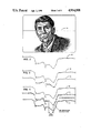
- FIG. 2 is a luminance plot across one scan line in a video picture
- FIG. 3 shows a run length representation of features in a video scan line
- FIG. 4 shows a run length representation of transitions about slope decision points of a video scan line
- FIG. 5 shows a representation of the reconstructed video scan line for display
- FIG. 6 shows a representation of how the run length data is converted to display data with transitions between runs
- FIG. 7 shows the system and method for compressing color video data in a video communication system including the additional processor subsystem
- FIG. 8 is a more detailed schematic diagram of a combined I/O control section, processor section, and input construction engine and reconstruction engine;
- FIG. 9 is a flow diagram illustrating the compression of digital word sizes of run length and color components
- FIG. 10 is a flow chart illustrating the additional signal processing of color video data.
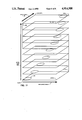
- FIG. 11 is an illustration of a three-dimensional color cube.
- each picture frame comprises a plurality of scan lines composed of a plurality of pixels, and the digitized color video signal which is used has three digital color components and a run length portion, the run length portion being of a first digital word size, and the three digital color components being of second, third and fourth digital word sizes, respectively.
- a histogram is created of up to a predetermined number of the most visually significant combinations of the color components in at least a portion of the picture frame.
- All of the digital color components in the picture frame are encoded to a look up table of digitally compressed color codes of a fifth digital word size smaller than the sum of second, third, and fourth digital word sizes; and the plurality of run lengths are encoded in combination with the digitally compressed color codes.
- the representation of color with such a limited number of codes allows for a significant reduction in the bit size necessary to represent the color data; and the use of run lengths allows for a further significant reduction in the amount of data required to represent pixels in a picture.
- a method of compressing digital color video data in a video communication system for transmitting a plurality of video picture frames, with each picture frame comprising a plurality of scan lines composed of a plurality of pixels, utilizing a digitized color video signal having three digital color components
- said video communication system including means for determining a luminance function for each pixel; means for determining which of said pixels on each scan line represent decision points based upon said luminance function; and means for encoding at least a portion of said plurality of pixels in each scan line as a plurality of combinations of run lengths and said three digital color components, said run length being of a first digital word size, and said three digital color components being of second, third and fourth digital word sizes, respectively; said method comprising the steps of determining up to a predetermined number of the visually significant occurring combinations of said color components in at least a portion of said picture frame; encoding all of said digital color components in said picture frame to a look up table in a memory means of digitally compressed color
- the present invention also accordingly provides for a system for compressing digital color video data in a video communication system for transmitting a plurality of video picture frames, with each picture frame comprising a plurality of scan lines composed of a plurality of pixels, utilizing a digitized color video signal having three digital color components, said video communication system including means for determining a luminance function for each pixel, means for determining which of said pixels on each scan line represent decision points based upon said luminance function, and means for encoding at least a portion of said plurality of pixels in each scan line as a plurality of combinations of run lengths and said three digital color components, said run lengths being of a first digital word size, and said three digital color components being of second, third, and fourth digital word sizes, respectively, said system of compressing digital color video data comprising: means for determining up to a predetermined number of the most visually significant combinations of said color components in at least a portion of said picture frame; means for encoding all of said digital color components in said picture frame to a look up table in
- the video communication system is capable of producing a color video picture using an RGB video camera, generating an analog RGB signal at the normal 60 fields per second, with each field representing half of the picture in an interlaced mode.
- the signal for the video picture frames generated by the camera 10 is received by an analog to digital converter 12, which converts the red, green and blue (RGB) analog components into digital RGB components, which are each digitized as six bit digital words, forming packets of bits for the RGB components for each pixel of the color video picture of eighteen bits.
- RGB red, green and blue
- the type of the device used to generate the source color video picture is not crucial to the invention, as a camera generating a standard NTSC composite signal which is converted to an RGB digital output would also be suitable as would a field rate differing from 60 fields/sec.
- the output of the camera also does not need to be strictly RGB, since other three color component groups may be used to create and transmit color video pictures.
- the tree digital color component signals may be cyan, magenta, and yellow; hue, saturation, and intensity; or even two distinct colors and a third parameter based upon the entire video signal, such as hue, saturation or intensity of an original analog video signal, so that there would be some automatic weighting of the color information generated by the camera.
- the three color components be represented by the same number of bits, since it is known in the television industry that certain ranges of colors are not as easily perceived by the human eye.
- Such a weighting of information could involve a reduction in the number of bits used for the red component in an RGB scheme, for example, thus permitting transmission of more gradations of other color information that is actually perceptible.
- the source of the color video pictures to be compressed may be a storage means, such as a video disk, a computer file storage media, a video tape, or the like from which the color video information can be processed for introduction into the color video data compression system of the invention.
- the digitized RGB signal is received by the transition engine portion 14 of the image capture engine 6, which preferably includes integrated circuit means and associated memory means.
- the first major part of the image capture engine is the transition engine which includes circuitry for determining a luminance function based upon the three color component video signal for each picture element, or pixel, of each scan line in the sequence of video picture frames generated by the analog front end of the system.
- the luminance converter 18 sums the bits from each of the three digital color components for each pixel in the scan lines of the video picture frame to get a luminance (or intensity) value and performs further processing of the data obtained.
- each scan line preferably contains 480 pixels, which matches the resolution of the camera and which provides for better resolution than is typically available in the prior art, in which generally only 256 pixels are utilized per scan line.
- the luminance of the three color components may be weighted to give greater significance to one color or two colors to provide the luminance function, and may also be based in part upon an original source analog video signal.
- the luminance function is preferably based in part at least upon the sum of the three digital color components.
- the luminance function derived from the sum of the three six bit color components therefore has a digital word size of eight bits.
- This luminance function for each pixel is utilized in the input capture engine for evaluating one or more decision parameters based upon the luminance function for determination of those pixels which operate as decision points about which the one or more of the decision parameters are found to vary from a prestored set of threshold values.
- the luminance function is an excellent indicator of color changes in the picture, or movements of objects in the picture.
- the one or more decision parameters based upon the luminance function may also be used as the basis for determination of differences from line to line, and of distinctive sequences of pixels which define edges of objects which can be determined to be moving from frame to frame.
- the luminance, or other combination of color components which comprise the luminance function undergoes significant changes where there are changes in the characteristics of the picture.
- the camera also introduces anomalies or artifacts into the video picture due to noise in the color sampling resolution which ideally should be eliminated to reduce the amount of data to be transmitted since they contribute nothing beneficial to the picture.
- the effect of such anomalies is averaged out by the human eye. Areas having a smooth appearance and little actual detail upon close observation seem to "crawl". This appearance is also known as the "mosquito effect".
- the picture takes on a grainy, speckled appearance.
- the impact of the noise on the luminance data is in the form of tiny variations in the computed luminance.
- the digitizing process also converts all of these artifacts to digital representations, even though they do not actually represent picture detail.
- the processing of luminance in the image capture engine operates to eliminate such meaningless details.
- One preferred method eliminating the non-essential details caused by noise in the luminance data is to determine the points of change based at least in part on the luminance function for pixels in the scan lines by comparing differences in one or more decision parameter with corresponding adaptive thresholds.
- the decision parameters are preferably comprised of differences of the luminance function between pixels, determined between proximate pixels (Diff-1) in a scan line, n plus one n plus two, or even a further distance away, where n represents the position on a scan line of the pixel being examined for changes in luminance; between adjacent first differences (Diff-2), and a cumulative parameter (Cum-diff) which is a sum of the individual difference functions Diff-1, and Diff-2.
- Each decision parameter has its own corresponding adaptive threshold, having a default value which is subject to modification by the system in response to operator settings.
- the adaptive threshold preferably has a default value which may be adjusted by the input capture engine responsive to operator or processor selections for resolution.
- the selecting of the threshold parameters for determining either the feature or transition decision points is quite subjective. The selection of the parameters determines the number of data points required to define the picture and it also determines the overall perceptual quality of the picture.
- Diff2 the cumulative change in luminance since the last decision point
- Diff2 the sum of two adjacent difference values
- INITS is the value of NDIFF2 immediately after the decision point.
- CUMDIFF in the slope case is defined the following way:
- the third decision parameter is also based upon NDIFF2:
- the threshold for TRIGVAL is usually set in the range of 4 to 10 and will trigger a decision point any time the absolute value reaches or exceeds the set value and the run length is at least 2 pixels. Other techniques may be used but these seem to give good quality pictures with an acceptable number of data points.
- FIG. 2 A graphic representation of a typical plot of luminance across a line of a video picture is shown in FIG. 2.
- the luminance function of the pixels intersected by the scan line 36 is graphically represented by line 38.
- a graph of the decision points based upon comparison of one of the decision parameters with the corresponding adaptive difference threshold in a feature encoding technique results in stepped line 40, a sequence of horizontal straight lines across the luminance pattern. Each horizontal line represents a separate length of a specific color.
- a second approach which may be used to eliminate the non-essential details is a transition or slope encoding technique, which is illustrated in FIG. 4.
- this technique the rate of change of the differences in the decision parameter between pixels is determined, and the rates of change of these differences are compared with an adaptive, prestored difference rate of change threshold to determine decision points or apex points. These change points or decision points are indicated as X's on line 39. They indicate the location of the next apex. "Run length" is the pixel distance between decision points, for both the feature encoding and slope encoding techniques.
- the luminance data results in a line 42 representing a series of apexes or slope decision points, which may be used for controlling the color segments between decision points.
- a drawing engine can produce a smooth transition of color values for the run length between decision points when the encoded information is to be retrieved.
- this technique for each scan line an initial color is transmitted, followed by as many sequences of run length and color values as are necessary to represent the picture frame content.
- the information is displayed as a series of slopes.
- For the run length encoded data artificial color slopes are inserted into the display line as shown in FIG. 5. In this case the slopes are generated as a function of the luminance shift between runs and the length of the adjoining runs as shown in FIG. 6.
- the decision point detector 26 for determining decision points may alternatively be able to utilize either one of these methods for fixing the decision points in the color of the pixels in the picture, as each method has its respective advantages and disadvantages.
- the feature coding technique is typically more appropriate for pictures with a complexity of objects with distinctive edges or lines.
- the slope encoding technique is most suitable for encoding gradual transitions in shading or gradual color changes, but may require additional coding to represent complex pictures with images having many edges and lines.
- a sequence of thresholds will be compared with decision parameters, and the cumulative parameter (Cum-diff) and an adaptive cumulative threshold will also be utilized in determining decision points, to account for those slow, gradual rates of change of luminance which would still result in an accumulated luminance change which is significant enough to merit identification of a decision point.
- the three component color codes are also operated on in the run length processor to drop the two least significant bits from the six bit values for the color components, reducing each of the color components in the preferred mode to four bit digital words.
- the transition engine may also contain a predetermined color map representation of three-component colors, with an n-bit code corresponding to a particular color combination.
- the colors of the image are matched as closely as possible with the colors in the color map.
- the color codes could also be rounded.
- the preferred bit size for the reduced color components is four bits, just as the input digital word size for the color components from the analog front end can be of different sizes to vary the informational content, the reduced digital color components may also be of different sizes.
- a particular combination of digital word sizes for color components may include a reduced size for the red component, due to the recognition in the industry of the reduced perceptibility of this component.
- the feature and slope encoding techniques allow for a variable number of bits to be used to represent an initial picture frame and then changes in subsequent picture frames, in order to encode the minimum number of bits for each picture frame. This is significant a improvement over the prior art which typically analyzes a four by four or three by three block of pixels to compress the information in such a block, which always results in the same number of bits being utilized to represent the informational content in the picture, whether there have been changes outside the segment or not.
- the second major portion of the image capture engine is the capture buffer memory (CBM) 29, which receives the encoded run lengths and reduced color components representing some 200 lines of data from the picture frame. Alternatively, if the data rate required becomes too high to send pictures at a desired speed, lesser numbers of scan lines can be stored, such as 150 or 100 lines.
- the run length and color component information in the capture buffer memory is then transmitted to the video data processor 30, which accesses the run length and color data in the capture buffer memory by an access control 35, and operates as an interface to transform and transmit the video information in a format suitable for transmission by the modem 32, connected to the telephone 34, and which may include means for further compressing the video data, at 33.
- the video data may also be compared with a previous picture frame stored in an old picture memory 31.
- a simplification processor 33 of a video data processor 30 it is possible in a simplification processor 33 of a video data processor 30 to further analyze the difference between color values of pixels after the color codes have been truncated to provide the reduced color component codes, and to concatenate run lengths of such reduced color component codes which vary less than a given threshold value, or to further concatenate run lengths of the reduced color codes based upon variance of one or more of the decision parameters with respect to a corresponding threshold.
- the run length code is typically at a maximum of four bits to be compatible with run length and color code combinations of 16 bits, with 16 bit computer buses in the current implementation, concatentation of a sequence of pixels for each run length would be expected to permit coding of up to sixteen pixels per run length.
- the values 0 to 15 are used to represent run lengths of from 2 to 17 pixels, since run lengths of 0 and 1 are not meaningful.
- longer run lengths may be determined initially as well, as may be compatible with different capacity computer buses, to permit run lengths of greater than 4 bits and run length color code combinations greater than 16 bits.
- the modem that is to be used is one which would utilize the largest bandwidth possible, and may be conventional 2400 bps or 9600 bps modem or special modems providing higher bit rates may be used.
- the output from capture buffer memory 129 is received by the processor subsystem 130 having standard input and output and control 166.
- the standard I/O 166 typically might include a keyboard, diskette control, a date and time clock, and a monitor output and control.
- Output from the processor subsystem 130 is typically connected to a modem 132, which is in turn connected to a telephone 134 for transmission of the compressed information over ordinary telephone lines.
- the video data processor subsystem 168 is most preferably adapted to be connected to both an input construction engine (I.C.E.) and a reconstruction engine (R.C.E.) for use in compressing and decompressing video color data in a two-way communication system.
- I.C.E. input construction engine
- R.C.E. reconstruction engine
- the reconstruction engine need not be connected to the same processor subsystem as is connected to the input construction engine. If a video communication system is configured so that the input construction system circuitry is part of a camera, and the reconstruction engine circuitry is part of a display monitor, different processor subsystems would generally be utilized by the input construction engine and the reconstruction engine.
- the shared video data processor subsystem receives input from shared capture memory buffer 170 for receiving input from the input construction engine, and preferably also sends output to a shared display memory buffer 172 which contains section 154, 158 and 160 of the drawing engine, for output to the reconstruction engine.
- shared display memory buffer 172 which contains section 154, 158 and 160 of the drawing engine, for output to the reconstruction engine.
- Each of these memory buffers requires sufficient capacity to avoid overflow the encoded information, and it has been found in practice that a memory space of 32K by 16 bits is adequate for these purposes.
- Memory buffer 170 is also preferably shared for input and output between the image capture engine and the video data processor; and the memory buffer 172 with its dual pingpong memory section is similarly shared for input and output between the reconstruction engine and the video data processor.
- the processor subsystem includes two microprocessors, which are preferably Motorola 68020 32 bit processors, processor "A” 174, and processor "B” 176.
- processors typically performs most of the processing functions of the processor subsystem, it is provided with a private data memory "A” 178 of 512K bytes.
- Processor "B” is provided with a lesser amount of memory in memory “B” 180 of 256K bytes.
- Also provided between processor "A” and processor "B” for communication between the processors is a dual port ram 182 of 16K bytes. Dual port RAMS 184 and 186 of 32K bytes are also provided as buffers between processors "A" and "B” and the I/O processor section 166.
- the microprocessor "C" 188 for the I/O control section 166 is preferably an Intel 80286 having DRAM refresh and a direct memory access 190 for diskette control and a DRAM 192 of 512K bytes.
- Input/output ports 194 are designated generally for the standard I/O, which may include disk drives, keyboard, a monitor, and the like.
- the run lengths 200 of a sequence of pixels in a scan line having like color values are determined as nine bit digital worlds which are divided in the input construction engine as four bit digital words 201.
- the RGB color components 202a, b, c as utilized for determining the luminance functions in section 118 are six bit digital words used for determining decision points for run lengths in the decision point logic 126. These colors are truncated by removing the two least significant bits from each six bit word in the color code truncation circuitry 120 to form four bit digital words 204a, b, c.
- the run length encoder 128 maps a series of run length and RGB color code combinations 205 to the capture buffer memory 129, in preparation for the further processing of the processor subsystem 130.
- a predetermined default color map 214 in the color code section 120 consisting of a look up table of unique combinations of the three color components such as RGB values and corresponding eight bit codes, maps 256 of the most visually significant color combinations out of a possible 4,096, obtained from the three RGB truncated four bit codes.
- the color map is preferably alterable by the video data processor subsystem.
- the 256 color code combinations to be included in the color map are determined on the following basis. Given that each RGB color component is represented as a four bit code, a range of 16 gradations of each color component is possible. However, in practice the colors at the extremes of each range of gradations rarely appear in images captured by a video camera. Statistical surveys of a wide variety of scenes captured by video cameras reveal a common distribution of colors. To illustrate the distribution, a two-dimensional chart of a range of from 0 to 16 of green downward along a vertical axis, with a range of from 0 to 16 of blue to the right across a horizontal axis yields an oval shaped pattern in the middle, along an axis from 0,0 to 15,15.
- Adding a third dimension of red yields an sausage-shaped distribution of the most visually significant color combinations from a wide variety of possible scenes and images.
- a combination selected from an extremity of this sausage-shaped distribution has been found to be virtually indistinguishable from a color combination at a nearby extremity of the three-dimensional color block, and within the sausage-shaped distribution, color combinations proximal to each other are also virtually indistinguishable.
- a color map can thus be constructed of the most visually significant color combinations likely to be encountered.
- an RGB ratio of 4:3:2 produces colors in the skin tone ranges, and this information can be used to balance the color ratio distribution, with the primary factor being subjective appearance.
- FIG. 11 shows a color cube with no color, black, in the front lower left corner and white which is the maximum red, green and blue in the upper right back corner. Green increases to the right from the black, all zeros, origin. Blue increases from the black toward the lower left back corner and red is represented by a number of planes representing constant levels of red. The red increases in the direction of the top of the cube. Thus all of the possible colors may be represented in the cube to a precision which is dependent on the number of bits allocated to each color component. Any specific color may be represented by the coordinates of any point within the cube.
- a histogram of the RGB color codes 212 is statistically processed for all of the run length combinations to update the color map 214 to be used as a look up table. Even with the four bit color codes for each of the RGB components, up to 4,096 different color combinations would be theoretically achievable. In practice, it has been found that a group of carefully selected 256 color combinations is quite adequate to serve as apex colors for the drawing engine to construct the image with up to 262,144 colors with six bit color reconstruction of each of the three color components. Alternatively further gradations are possible by reconstructing each of the three color components as eight bit codes.
- the histogram of 256 of the most frequent RGB color combinations may be used to modify the colors encoded as a series of eight bit digital words in the color code look up table or color map 214. Since each color combination in the color map represents a block of ranges of colors, the color frequency histogram may be used to substitute a more frequently occurring color combination within its color block as a representative color combination, for more faithful color reproduction. As these representative colors are within the color block for those colors, the substituted colors are determined by the system are visually significant, and are not merely selected upon frequency of appearance in the picture.
- the RGB color information requirement for 12 bits to represent the maximum of 4,096 colors is thus reduced to a table of 256 8 bit digital words to represent the 256 most visually significant colors. Less frequently occurring colors which may be over the limit of 256 colors may also forced to conform to the same coloration as the nearest color code combination in the color map, without significant lessening of the accuracy of the colors in the picture frame to be transmitted.
- the color codes are in the form of eight bit digital words 206 which may be combined with the four bit run length portion 200, the four bit run length code, which actually represents a run length of from 2 to 17 pixels in the preferred implementation of the encoding of run lengths, can be statistically processed to provide a varying length digital word 208 to be assembled in the eventual fully processed run length color code combination 210.
- the run length codes may vary from one bit for most frequent lengths up to 8 or 10 for rarely occurring lengths.
- the run length may represent from 2 to 257 pixels, which would be theoretically adequate to represent an entire scan line of 512 pixels in two run length color code combinations.
- the four bit run lengths are concatenated where possible at 216 finally before encoding the run length and color code combinations at 218.
- the color code look up table 214 it is also necessary to construct and encode the color code look up table 214 as a table of 256 individual four bit color codes for each of the RGB components, which would be transmitted with the color code run length combinations to enable a receiver or translator of the picture information to decode compressed color information.
- More advanced processing and compression of the run length color code combinations may also occur in the advanced processing section 220. Similar to the pixel to pixel differencing and comparison for determination of decision points in the input construction engine, adjacent scan lines may be compared to formulate a table of scan lines which do not differ from the previous scan line in the direction of scanning, so that the lines or portions of lines may be merely duplicated. Thus, this would allow further compression of the run length and color code combinations 210 as a differences table 222.
- Another technique termed subframe processing may be used to reduce the amount of data which must be sent to update a new picture on the receiving section of a system. This subframe processing technique samples every nth line and continues processing only with those lines for any one image.
- Distinctive segments of run length combinations which appear to form an edge may be detected in an edge detector 224 to monitor the displacement of such segments from frame-to-frame by movement analysis 226, which preferably could track the movement of such scan line segments in groups of scan line segments according to any horizontal shifting, shrinking, growing, or vertical displacement of such segments, or virtually any combination of such movements.
- a further level of compression involves the frame-to-frame differencing by comparison of the run length and color codes combination information from the last picture frame with the current picture frame, and encoding of a skip code to identify those portions which have not changed, so that only the run length and color code combinations which have changed are encoded at 228.
- the processor subsystem also preferably encodes the run length and color code combinations to be transmitted from the processor subsystem by determining a histogram of the occurrence of run length and color code combinations.
- the preferred form of statistical encoding at this stage is similar to Huffman coding, and involves the assignment of the most frequently occurring combination to a table of one bit digital words, at 230. This table is to be utilized at the receiving end of the system by referring to one or the other of the bit states of the one bit digital word to fill in this most frequently occurring run length combination in a corresponding run length color code table.
- the receiving table would be filled in with the run length color code combination, and would otherwise be left with a marker of zero indicating that the spot in the table was to be filled in later.
- the next three most occurring combination are then represented as a two bit length digital word, with one of the binary bit states again indicating that the receiving table location was to be filled in later, and the next three most frequently occurring combinations are filled in their respective locations in the corresponding receiving table.
- a three bit digital word table can then be constructed in a similar fashion to designate the next seven most frequently occurring values, with one of the binary bit states representing values to be filled in later, and so on, with a final digital word size of eight bits used to represent the remaining color code combinations.
- This process may be applied to other groupings than the 1, 2, 3, n bit grouping sequence described above.
- this statistical encoding of the compressed run length color code information is performed for at least the color codes, individually, with the run length portions then being encoded and received as a separate table of eight bit digital words, but it is also possible to separately statistically encode the eight bit run length portions in similar fashion and transmit a separate statistically encoded table for the run length components of the run length-color code combinations.
- Other similar statistical encoding approaches may also be appropriate as an alternative.
- the method and system of the invention result in a compression color video data by the truncation of least significant information from the color component codes, and the statistical encoding of the most visually significant color code combinations.
- Further processing of the color video data allows the further compression of the data by encoding concatenated run lengths, line-to-line differences, movement of segments of picture frames and portions of picture frames which have changed to reduce the amount of information to be encoded to the minimum amount.
- the invention further provides for the additional compression of data to be encoded by a form of statistical encoding, to reduce the amount of information to be transmitted by the system to the bare minimum.
- the method and system for compressing color video data can achieve a significant elimination of extraneous noise introduced by a video camera, and can result in a significant improvement in coding of the minimum amount of information necessary to reconstruct color video picture frames in a real time sequencing of video pictures.
- the invention may be also be adapted for use in compressing color video data on magnetic media, such as hard disks or high capacity magnetic floppy discs which may be used in storing and communicating such data via computer systems, or on video discs for video disc players which could transmit the information in the form of a video movie.
- magnetic media such as hard disks or high capacity magnetic floppy discs which may be used in storing and communicating such data via computer systems, or on video discs for video disc players which could transmit the information in the form of a video movie.
Abstract
Description
NDIFF2=(luminance.sub.(i+2) -luminance.sub.(i))/2
CUMDIFF.sub.(i) =CUMDIFF.sub.(i-1) +NDIFF2.sub.(i)
TRIGVAL.sub.(i)=NDIFF2.sub.(i) -INITS
Claims (18)
Priority Applications (16)
| Application Number | Priority Date | Filing Date | Title |
|---|---|---|---|
| US07/186,637 US4914508A (en) | 1988-04-27 | 1988-04-27 | Method and system for compressing and statistically encoding color video data |
| KR1019890702453A KR950015103B1 (en) | 1988-04-27 | 1989-03-23 | Method and system for compressing and decompressing digital color video statistically encoded data |
| AU33542/89A AU616006B2 (en) | 1988-04-27 | 1989-03-23 | Method and system for compressing and decompressing digital color video statistically encoded data |
| JP1503910A JP2583627B2 (en) | 1988-04-27 | 1989-03-23 | Method and apparatus for compressing and decompressing statistically encoded data for digital color video |
| BR898906930A BR8906930A (en) | 1988-04-27 | 1989-03-23 | PROCESS AND SYSTEM FOR COMPACTING AND DECOMPACTING DATA IN COLOR DIGITAL VIDEO IN A VIDEO COMMUNICATION SYSTEM |
| PCT/US1989/001182 WO1989010673A1 (en) | 1988-04-27 | 1989-03-23 | Method and system for compressing and decompressing digital color video statistically encoded data |
| CA000594758A CA1322240C (en) | 1988-04-27 | 1989-03-23 | Method and system for compressing and decompressing digital color video statistically encoded data |
| ZA892766A ZA892766B (en) | 1988-04-27 | 1989-04-14 | Method and system for compressing and decompressing digital color video statistically encoded data |
| IL90025A IL90025A0 (en) | 1988-04-27 | 1989-04-19 | Method and system for compressing and decompressing digital color video statistically encoded data |
| NZ228808A NZ228808A (en) | 1988-04-27 | 1989-04-19 | Compression of digital colour video data using memory lookup tables |
| EP89304129A EP0339948B1 (en) | 1988-04-27 | 1989-04-26 | Compressing and decompressing digital color video statistically encoded data |
| AT89304129T ATE125995T1 (en) | 1988-04-27 | 1989-04-26 | COMPRESSION AND DECOMPRESSION OF DIGITAL STATISTICALLY CODED COLOR VIDEO DATA. |
| DE68923648T DE68923648T2 (en) | 1988-04-27 | 1989-04-26 | Compression and decompression of digital, statistically coded color video data. |
| PT90390A PT90390B (en) | 1988-04-27 | 1989-04-27 | PROCESS AND DEVICE FOR COMPRESSING AND DECOMPRESSING DIGITAL COLOR VIDEO DATA, ESTATISTICALLY ENCODED |
| MX015845A MX166127B (en) | 1988-04-27 | 1989-04-27 | METHOD AND SYSTEM FOR COMPRESSING AND DECOMPRESSING STATISTICALLY CODED DATA FROM DIGITAL COLOR VIDEO |
| FI896255A FI896255A0 (en) | 1988-04-27 | 1989-12-22 | FOERFARANDE OCH SYSTEM FOER KOMPRESSION OCH DEKOMPRESSION AV STATISTISTIC KODADE DIGITALA FAERGVIDEODATA. |
Applications Claiming Priority (1)
| Application Number | Priority Date | Filing Date | Title |
|---|---|---|---|
| US07/186,637 US4914508A (en) | 1988-04-27 | 1988-04-27 | Method and system for compressing and statistically encoding color video data |
Publications (1)
| Publication Number | Publication Date |
|---|---|
| US4914508A true US4914508A (en) | 1990-04-03 |
Family
ID=22685720
Family Applications (1)
| Application Number | Title | Priority Date | Filing Date |
|---|---|---|---|
| US07/186,637 Expired - Lifetime US4914508A (en) | 1988-04-27 | 1988-04-27 | Method and system for compressing and statistically encoding color video data |
Country Status (2)
| Country | Link |
|---|---|
| US (1) | US4914508A (en) |
| ZA (1) | ZA892766B (en) |
Cited By (46)
| Publication number | Priority date | Publication date | Assignee | Title |
|---|---|---|---|---|
| US5070532A (en) * | 1990-09-26 | 1991-12-03 | Radius Inc. | Method for encoding color images |
| US5132992A (en) * | 1991-01-07 | 1992-07-21 | Paul Yurt | Audio and video transmission and receiving system |
| US5140412A (en) * | 1990-11-09 | 1992-08-18 | Uvc Corporation | Method for color encoding and pixelization for image reconstruction |
| US5179442A (en) * | 1989-06-02 | 1993-01-12 | North American Philips Corporation | Method and apparatus for digitally processing a high definition television augmentation signal |
| US5237409A (en) * | 1990-09-10 | 1993-08-17 | Brother Kogyo Kabushiki Kaisha | Color image forming apparatus using color compressed color data |
| US5247589A (en) * | 1990-09-26 | 1993-09-21 | Radius Inc. | Method for encoding color images |
| US5253275A (en) * | 1991-01-07 | 1993-10-12 | H. Lee Browne | Audio and video transmission and receiving system |
| US5448296A (en) * | 1993-04-23 | 1995-09-05 | Music; John D. | Variable parameter block coding and data compression system |
| US5453787A (en) * | 1993-12-10 | 1995-09-26 | International Business Machines Corporation | Variable spatial frequency chrominance encoding in software motion video compression |
| US5465118A (en) * | 1993-12-17 | 1995-11-07 | International Business Machines Corporation | Luminance transition coding method for software motion video compression/decompression |
| US5583656A (en) * | 1992-12-31 | 1996-12-10 | Eastman Kodak Company | Methods and apparatus for attaching compressed look-up table (LUT) representations of N to M-dimensional transforms to image data and for processing image data utilizing the attached compressed LUTs |
| US5627765A (en) * | 1994-07-25 | 1997-05-06 | Avid Technology, Inc. | Method and apparatus for compressing and analyzing video and for creating a reference video |
| US5671319A (en) * | 1992-07-31 | 1997-09-23 | Nec Corporation | Compression of video and audio signals and expansion of a compressed signal in accordance with an image hf component compression factor |
| US5699476A (en) * | 1990-02-22 | 1997-12-16 | U.S. Philips Corporation | Method and apparatus for transmitting and/or storing a series of hierarchically encoded digital image data blocks |
| US5838266A (en) * | 1990-12-12 | 1998-11-17 | Universal Video Communications Corp. | Data processing apparatus and method using data compression |
| US6002720A (en) * | 1991-01-07 | 1999-12-14 | H. Lee Browne, D/B/A Greenwich Information Technologies Llc | Audio and video transmission and receiving system |
| US6061475A (en) * | 1998-03-20 | 2000-05-09 | Axcess, Inc. | Video compression apparatus and method |
| US6067320A (en) * | 1996-03-15 | 2000-05-23 | Matsushita Electric Industrial Co., Ltd. | Method and apparatus for encoding and decoding images |
| US6108378A (en) * | 1993-12-30 | 2000-08-22 | Deutsche Thomson-Brandt Gmbh | Video encoder and decoder image motion estimation system with reduced computation |
| US6195128B1 (en) * | 1995-08-25 | 2001-02-27 | Eidos Technologies Limited | Video processing for storage or transmission |
| WO2001046916A2 (en) | 1999-12-22 | 2001-06-28 | Axcess Inc. | Method and system for operating an amusement park |
| US6404927B1 (en) * | 1999-03-15 | 2002-06-11 | Exar Corporation | Control point generation and data packing for variable length image compression |
| US20030067471A1 (en) * | 2001-09-28 | 2003-04-10 | Ying Cui | Window idle frame memory compression |
| US20030095126A1 (en) * | 2001-11-20 | 2003-05-22 | Koninklijke Philips Electronics N.V. | Color burst queue for a shared memory controller in a color sequential display system |
| US20040058240A1 (en) * | 2002-09-20 | 2004-03-25 | 3M Innovative Properties Company | Anode compositions having an elastomeric binder and an adhesion promoter |
| US6720894B2 (en) * | 2002-05-29 | 2004-04-13 | Broadcom Corporation | Method of and system for performing differential lossless compression |
| US20040071355A1 (en) * | 2002-10-11 | 2004-04-15 | Ira Liao | Device and method for compressing and decompressing data for graphics display |
| US6804356B1 (en) * | 2000-03-20 | 2004-10-12 | Koninklijke Philips Electronics N.V. | Hierarchical authentication system for images and video |
| US20040247192A1 (en) * | 2000-06-06 | 2004-12-09 | Noriko Kajiki | Method and system for compressing motion image information |
| US6898327B1 (en) * | 2000-03-23 | 2005-05-24 | International Business Machines Corporation | Anti-flicker system for multi-plane graphics |
| US6912305B1 (en) * | 1998-09-08 | 2005-06-28 | Access Systems Ltd | Computer animation |
| US7072521B1 (en) * | 2000-06-19 | 2006-07-04 | Cadwell Industries, Inc. | System and method for the compression and quantitative measurement of movement from synchronous video |
| US20060214819A1 (en) * | 2002-12-16 | 2006-09-28 | Yoshihiko Deoka | Image encoding device and method, and encoded image decoding device and method |
| EP1708366A1 (en) * | 2005-03-22 | 2006-10-04 | Agilent Technologies Inc | A data compressor with value range detection |
| US20060222076A1 (en) * | 2005-04-01 | 2006-10-05 | Microsoft Corporation | Special predictive picture encoding using color key in source content |
| US7301944B1 (en) | 1997-10-24 | 2007-11-27 | Tranz-Send Broadcasting Network, Inc. | Media file distribution with adaptive transmission protocols |
| US20090175534A1 (en) * | 2008-01-07 | 2009-07-09 | Fuji Xerox Co., Ltd. | Binarizing device and computer readable medium |
| US11128076B2 (en) | 2019-01-21 | 2021-09-21 | Cadwell Laboratories, Inc. | Connector receptacle |
| US11185684B2 (en) | 2018-09-18 | 2021-11-30 | Cadwell Laboratories, Inc. | Minimally invasive two-dimensional grid electrode |
| US11317841B2 (en) | 2018-11-14 | 2022-05-03 | Cadwell Laboratories, Inc. | Method and system for electrode verification |
| US11471087B2 (en) | 2018-11-09 | 2022-10-18 | Cadwell Laboratories, Inc. | Integrity verification system for testing high channel count neuromonitoring recording equipment |
| US11517239B2 (en) | 2018-04-05 | 2022-12-06 | Cadwell Laboratories, Inc. | Systems and methods for processing and displaying electromyographic signals |
| US11517245B2 (en) | 2018-10-30 | 2022-12-06 | Cadwell Laboratories, Inc. | Method and system for data synchronization |
| US11529107B2 (en) | 2018-11-27 | 2022-12-20 | Cadwell Laboratories, Inc. | Methods for automatic generation of EEG montages |
| US11596337B2 (en) | 2018-04-24 | 2023-03-07 | Cadwell Laboratories, Inc | Methods and systems for operating an intraoperative neurophysiological monitoring system in conjunction with electrocautery procedures |
| US11950972B2 (en) | 2016-12-12 | 2024-04-09 | Cadwell Laboratories, Inc. | Controller, adapter and connector systems for high density electrode management |
Citations (46)
| Publication number | Priority date | Publication date | Assignee | Title |
|---|---|---|---|---|
| US3414677A (en) * | 1964-12-28 | 1968-12-03 | Itt | Time-bandwidth reduction by dividing binary type signal into groups and producing coded signal of predetermined characteristic in response to each group |
| US3609244A (en) * | 1969-12-18 | 1971-09-28 | Bell Telephone Labor Inc | Conditional replenishment video system with variable length address code |
| US3767847A (en) * | 1971-07-01 | 1973-10-23 | Bell Telephone Labor Inc | Frame-to-frame redundancy reduction system which transmits an intraframe coded signal |
| US3950607A (en) * | 1973-04-30 | 1976-04-13 | Colorado Video, Inc. | Bandwidth compression system and method |
| US3976831A (en) * | 1973-12-20 | 1976-08-24 | Telefonaktiebolaget L M Ericsson | Method for transmitting pictures at a picture telephone transmission having limited bandwidth |
| US3980830A (en) * | 1974-05-03 | 1976-09-14 | Licentia Patent-Verwaltungs-G.M.B.H. | Compatible picturephone system |
| US3982063A (en) * | 1975-02-03 | 1976-09-21 | Bell Telephone Laboratories, Incorporated | Methods and apparatus for reducing the bandwidth of a video signal |
| US4004084A (en) * | 1976-03-03 | 1977-01-18 | Bell Telephone Laboratories, Incorporated | Video conferencing system using spatial reduction and temporal resolution |
| US4027331A (en) * | 1974-08-02 | 1977-05-31 | The Post Office | Digital television system |
| US4058835A (en) * | 1974-11-08 | 1977-11-15 | Westinghouse Electric Corporation | Scan conversion apparatus |
| US4060832A (en) * | 1975-07-03 | 1977-11-29 | Societe Anonyme De Telecommunications | Digit rate reducing method in video signal transmission |
| US4090221A (en) * | 1972-03-13 | 1978-05-16 | Bell Telephone Laboratories, Incorporated | Apparatus for improving video signal-to-noise ratio |
| US4179709A (en) * | 1978-01-10 | 1979-12-18 | Bell & Howell Company | Video information bandwidth compression |
| US4210927A (en) * | 1977-05-11 | 1980-07-01 | Hitachi, Ltd. | Method for transmitting a color video signal on a narrow-band transmission line |
| US4222076A (en) * | 1978-09-15 | 1980-09-09 | Bell Telephone Laboratories, Incorporated | Progressive image transmission |
| US4261018A (en) * | 1979-06-18 | 1981-04-07 | Bell Telephone Laboratories, Incorporated | Progressive image transmission |
| US4302775A (en) * | 1978-12-15 | 1981-11-24 | Compression Labs, Inc. | Digital video compression system and methods utilizing scene adaptive coding with rate buffer feedback |
| US4306249A (en) * | 1978-12-20 | 1981-12-15 | British Broadcasting Corporation | Digital signal processing method and apparatus |
| US4323916A (en) * | 1980-02-07 | 1982-04-06 | Rca Corporation | Data rate reduction for digital video signals by subsampling and adaptive reconstruction |
| US4365273A (en) * | 1979-11-05 | 1982-12-21 | Dainippon Screen Seizo Kabushiki Kaisha | Picture data compressing method |
| US4394774A (en) * | 1978-12-15 | 1983-07-19 | Compression Labs, Inc. | Digital video compression system and methods utilizing scene adaptive coding with rate buffer feedback |
| US4420771A (en) * | 1981-02-09 | 1983-12-13 | Bell Telephone Laboratories, Incorporated | Technique for encoding multi-level signals |
| US4455571A (en) * | 1981-03-10 | 1984-06-19 | Victor Company Of Japan, Ltd. | Compression system and compression and expansion system for a composite video signal |
| US4468708A (en) * | 1981-10-30 | 1984-08-28 | Ampex Corporation | Combined data rate reduction system |
| US4485400A (en) * | 1981-01-13 | 1984-11-27 | Lemelson Jerome H | Video telephone |
| US4494144A (en) * | 1982-06-28 | 1985-01-15 | At&T Bell Laboratories | Reduced bandwidth video transmission |
| US4541012A (en) * | 1982-01-04 | 1985-09-10 | Compression Labs, Inc. | Video bandwidth reduction system employing interframe block differencing and transform domain coding |
| US4546383A (en) * | 1982-06-18 | 1985-10-08 | Inria Institute National De Recherche En Informatique Et En Automatique | Method and apparatus for visual telecommunications, in particular for use by the deaf |
| US4573074A (en) * | 1982-12-09 | 1986-02-25 | Cselt Centro Studi E Laboratori Telecomunicazioni S.P.A. | Coding and decoding method and system for variable-length sequences of digital data |
| US4589110A (en) * | 1981-06-24 | 1986-05-13 | At&T Bell Laboratories | Signal processor (system) for reducing bandwidth and for multiplexing a plurality of signals onto a single communications link |
| US4597010A (en) * | 1982-07-23 | 1986-06-24 | British Telecommunications | Video data transmission |
| US4605963A (en) * | 1983-08-15 | 1986-08-12 | Rca Corporation | Reduction of control bits for adaptive sub-nyquist encoder |
| US4633296A (en) * | 1982-10-14 | 1986-12-30 | British Telecommunications Public Limited Company | Omission and subsequent estimation of zero sequency coefficients of transformed digitized images to facilitate data compression |
| US4633311A (en) * | 1981-06-24 | 1986-12-30 | At&T Bell Laboratories | Signal processor (system) for reducing bandwidth and for multiplexing a plurality of signals onto a single communications link |
| US4654484A (en) * | 1983-07-21 | 1987-03-31 | Interand Corporation | Video compression/expansion system |
| US4654695A (en) * | 1985-03-25 | 1987-03-31 | Rca Corporation | Apparatus for reducing the resolution of video samples by truncating the most significant bits |
| US4656511A (en) * | 1983-09-30 | 1987-04-07 | Nec Corporation | Video signal compressing and coding apparatus |
| US4704628A (en) * | 1986-07-16 | 1987-11-03 | Compression Labs, Inc. | Combined intraframe and interframe transform coding system |
| US4719503A (en) * | 1986-06-18 | 1988-01-12 | Rca Corporation | Display processor with color matrixing circuitry and two map memories storing chrominance-only data |
| US4740832A (en) * | 1986-10-14 | 1988-04-26 | Technology, Inc., 64 | Image storage using separately scanned luminance and chrominance variables |
| US4758881A (en) * | 1987-06-02 | 1988-07-19 | Eastman Kodak Company | Still video frame store memory |
| US4772956A (en) * | 1987-06-02 | 1988-09-20 | Eastman Kodak Company | Dual block still video compander processor |
| US4772938A (en) * | 1986-10-03 | 1988-09-20 | Eastman Kodak Company | Color video signal frame store |
| US4774562A (en) * | 1987-06-02 | 1988-09-27 | Eastman Kodak Company | Image transmission system with preview mode |
| US4774587A (en) * | 1987-06-02 | 1988-09-27 | Eastman Kodak Company | Still video transceiver processor |
| US4785349A (en) * | 1987-10-05 | 1988-11-15 | Technology Inc. 64 | Digital video decompression system |
-
1988
- 1988-04-27 US US07/186,637 patent/US4914508A/en not_active Expired - Lifetime
-
1989
- 1989-04-14 ZA ZA892766A patent/ZA892766B/en unknown
Patent Citations (46)
| Publication number | Priority date | Publication date | Assignee | Title |
|---|---|---|---|---|
| US3414677A (en) * | 1964-12-28 | 1968-12-03 | Itt | Time-bandwidth reduction by dividing binary type signal into groups and producing coded signal of predetermined characteristic in response to each group |
| US3609244A (en) * | 1969-12-18 | 1971-09-28 | Bell Telephone Labor Inc | Conditional replenishment video system with variable length address code |
| US3767847A (en) * | 1971-07-01 | 1973-10-23 | Bell Telephone Labor Inc | Frame-to-frame redundancy reduction system which transmits an intraframe coded signal |
| US4090221A (en) * | 1972-03-13 | 1978-05-16 | Bell Telephone Laboratories, Incorporated | Apparatus for improving video signal-to-noise ratio |
| US3950607A (en) * | 1973-04-30 | 1976-04-13 | Colorado Video, Inc. | Bandwidth compression system and method |
| US3976831A (en) * | 1973-12-20 | 1976-08-24 | Telefonaktiebolaget L M Ericsson | Method for transmitting pictures at a picture telephone transmission having limited bandwidth |
| US3980830A (en) * | 1974-05-03 | 1976-09-14 | Licentia Patent-Verwaltungs-G.M.B.H. | Compatible picturephone system |
| US4027331A (en) * | 1974-08-02 | 1977-05-31 | The Post Office | Digital television system |
| US4058835A (en) * | 1974-11-08 | 1977-11-15 | Westinghouse Electric Corporation | Scan conversion apparatus |
| US3982063A (en) * | 1975-02-03 | 1976-09-21 | Bell Telephone Laboratories, Incorporated | Methods and apparatus for reducing the bandwidth of a video signal |
| US4060832A (en) * | 1975-07-03 | 1977-11-29 | Societe Anonyme De Telecommunications | Digit rate reducing method in video signal transmission |
| US4004084A (en) * | 1976-03-03 | 1977-01-18 | Bell Telephone Laboratories, Incorporated | Video conferencing system using spatial reduction and temporal resolution |
| US4210927A (en) * | 1977-05-11 | 1980-07-01 | Hitachi, Ltd. | Method for transmitting a color video signal on a narrow-band transmission line |
| US4179709A (en) * | 1978-01-10 | 1979-12-18 | Bell & Howell Company | Video information bandwidth compression |
| US4222076A (en) * | 1978-09-15 | 1980-09-09 | Bell Telephone Laboratories, Incorporated | Progressive image transmission |
| US4302775A (en) * | 1978-12-15 | 1981-11-24 | Compression Labs, Inc. | Digital video compression system and methods utilizing scene adaptive coding with rate buffer feedback |
| US4394774A (en) * | 1978-12-15 | 1983-07-19 | Compression Labs, Inc. | Digital video compression system and methods utilizing scene adaptive coding with rate buffer feedback |
| US4306249A (en) * | 1978-12-20 | 1981-12-15 | British Broadcasting Corporation | Digital signal processing method and apparatus |
| US4261018A (en) * | 1979-06-18 | 1981-04-07 | Bell Telephone Laboratories, Incorporated | Progressive image transmission |
| US4365273A (en) * | 1979-11-05 | 1982-12-21 | Dainippon Screen Seizo Kabushiki Kaisha | Picture data compressing method |
| US4323916A (en) * | 1980-02-07 | 1982-04-06 | Rca Corporation | Data rate reduction for digital video signals by subsampling and adaptive reconstruction |
| US4485400A (en) * | 1981-01-13 | 1984-11-27 | Lemelson Jerome H | Video telephone |
| US4420771A (en) * | 1981-02-09 | 1983-12-13 | Bell Telephone Laboratories, Incorporated | Technique for encoding multi-level signals |
| US4455571A (en) * | 1981-03-10 | 1984-06-19 | Victor Company Of Japan, Ltd. | Compression system and compression and expansion system for a composite video signal |
| US4633311A (en) * | 1981-06-24 | 1986-12-30 | At&T Bell Laboratories | Signal processor (system) for reducing bandwidth and for multiplexing a plurality of signals onto a single communications link |
| US4589110A (en) * | 1981-06-24 | 1986-05-13 | At&T Bell Laboratories | Signal processor (system) for reducing bandwidth and for multiplexing a plurality of signals onto a single communications link |
| US4468708A (en) * | 1981-10-30 | 1984-08-28 | Ampex Corporation | Combined data rate reduction system |
| US4541012A (en) * | 1982-01-04 | 1985-09-10 | Compression Labs, Inc. | Video bandwidth reduction system employing interframe block differencing and transform domain coding |
| US4546383A (en) * | 1982-06-18 | 1985-10-08 | Inria Institute National De Recherche En Informatique Et En Automatique | Method and apparatus for visual telecommunications, in particular for use by the deaf |
| US4494144A (en) * | 1982-06-28 | 1985-01-15 | At&T Bell Laboratories | Reduced bandwidth video transmission |
| US4597010A (en) * | 1982-07-23 | 1986-06-24 | British Telecommunications | Video data transmission |
| US4633296A (en) * | 1982-10-14 | 1986-12-30 | British Telecommunications Public Limited Company | Omission and subsequent estimation of zero sequency coefficients of transformed digitized images to facilitate data compression |
| US4573074A (en) * | 1982-12-09 | 1986-02-25 | Cselt Centro Studi E Laboratori Telecomunicazioni S.P.A. | Coding and decoding method and system for variable-length sequences of digital data |
| US4654484A (en) * | 1983-07-21 | 1987-03-31 | Interand Corporation | Video compression/expansion system |
| US4605963A (en) * | 1983-08-15 | 1986-08-12 | Rca Corporation | Reduction of control bits for adaptive sub-nyquist encoder |
| US4656511A (en) * | 1983-09-30 | 1987-04-07 | Nec Corporation | Video signal compressing and coding apparatus |
| US4654695A (en) * | 1985-03-25 | 1987-03-31 | Rca Corporation | Apparatus for reducing the resolution of video samples by truncating the most significant bits |
| US4719503A (en) * | 1986-06-18 | 1988-01-12 | Rca Corporation | Display processor with color matrixing circuitry and two map memories storing chrominance-only data |
| US4704628A (en) * | 1986-07-16 | 1987-11-03 | Compression Labs, Inc. | Combined intraframe and interframe transform coding system |
| US4772938A (en) * | 1986-10-03 | 1988-09-20 | Eastman Kodak Company | Color video signal frame store |
| US4740832A (en) * | 1986-10-14 | 1988-04-26 | Technology, Inc., 64 | Image storage using separately scanned luminance and chrominance variables |
| US4758881A (en) * | 1987-06-02 | 1988-07-19 | Eastman Kodak Company | Still video frame store memory |
| US4772956A (en) * | 1987-06-02 | 1988-09-20 | Eastman Kodak Company | Dual block still video compander processor |
| US4774562A (en) * | 1987-06-02 | 1988-09-27 | Eastman Kodak Company | Image transmission system with preview mode |
| US4774587A (en) * | 1987-06-02 | 1988-09-27 | Eastman Kodak Company | Still video transceiver processor |
| US4785349A (en) * | 1987-10-05 | 1988-11-15 | Technology Inc. 64 | Digital video decompression system |
Non-Patent Citations (12)
| Title |
|---|
| Chen & Smith, "Adaptive Coding of Monochrome and Color Images", IEEE Transactions on Communication, vol. COM-25, No. 11, Nov. 19, 1977. |
| Chen & Smith, Adaptive Coding of Monochrome and Color Images , IEEE Transactions on Communication, vol. COM 25, No. 11, Nov. 19, 1977. * |
| Gerken & Schiller, "A Low Bit-Rate Image Sequence Coder Combining A Progressive DPCM On Interleaved Raster With A Hybrid DCT Technique", IEEE Journal on Selected Areas in Communications, vol. SAC-5, No. 7, Aug., 1987. |
| Gerken & Schiller, A Low Bit Rate Image Sequence Coder Combining A Progressive DPCM On Interleaved Raster With A Hybrid DCT Technique , IEEE Journal on Selected Areas in Communications, vol. SAC 5, No. 7, Aug., 1987. * |
| Heiman & Rose, "A Look-Up-Based Universal Real-Time Transformer for Image Coding", IEEE Journal on Selected Areas in Communications, vol. SAC-5, No. 7, Aug. 1987. |
| Heiman & Rose, A Look Up Based Universal Real Time Transformer for Image Coding , IEEE Journal on Selected Areas in Communications, vol. SAC 5, No. 7, Aug. 1987. * |
| Kaneko, Hatori & Koike, "Improvements of Transform Coding Algorithm for Motion-Compensated Interframe Prediction Errors-DCT/SQ Coding," IEEE Journal on Selected Areas in Communications, vol. SAC-5, No. 7, Aug., 1987. |
| Kaneko, Hatori & Koike, Improvements of Transform Coding Algorithm for Motion Compensated Interframe Prediction Errors DCT/SQ Coding, IEEE Journal on Selected Areas in Communications, vol. SAC 5, No. 7, Aug., 1987. * |
| Kato, Mukawa & Okubo, "A Motion Picture Coding Algorithm Using Adaptive DCT Encoding Based on Coefficient Power Distribution Classification", vol. SAC-5, No. 7, Aug., 1987. |
| Kato, Mukawa & Okubo, A Motion Picture Coding Algorithm Using Adaptive DCT Encoding Based on Coefficient Power Distribution Classification , vol. SAC 5, No. 7, Aug., 1987. * |
| Moorehead II, Rajala & Cook, "Image Sequence Compression Using A Pel-Recursive Motion-Compensated Technique", IEEE Journal on Selected Areas In Communications, vol. SAC-5, No. 7, Aug., 1987. |
| Moorehead II, Rajala & Cook, Image Sequence Compression Using A Pel Recursive Motion Compensated Technique , IEEE Journal on Selected Areas In Communications, vol. SAC 5, No. 7, Aug., 1987. * |
Cited By (86)
| Publication number | Priority date | Publication date | Assignee | Title |
|---|---|---|---|---|
| US5179442A (en) * | 1989-06-02 | 1993-01-12 | North American Philips Corporation | Method and apparatus for digitally processing a high definition television augmentation signal |
| US5699476A (en) * | 1990-02-22 | 1997-12-16 | U.S. Philips Corporation | Method and apparatus for transmitting and/or storing a series of hierarchically encoded digital image data blocks |
| US5237409A (en) * | 1990-09-10 | 1993-08-17 | Brother Kogyo Kabushiki Kaisha | Color image forming apparatus using color compressed color data |
| US5070532A (en) * | 1990-09-26 | 1991-12-03 | Radius Inc. | Method for encoding color images |
| US5247589A (en) * | 1990-09-26 | 1993-09-21 | Radius Inc. | Method for encoding color images |
| US5140412A (en) * | 1990-11-09 | 1992-08-18 | Uvc Corporation | Method for color encoding and pixelization for image reconstruction |
| US5838266A (en) * | 1990-12-12 | 1998-11-17 | Universal Video Communications Corp. | Data processing apparatus and method using data compression |
| US20030031248A1 (en) * | 1991-01-07 | 2003-02-13 | Acacia Media Technologies Corporation | Audio and video transmission and receiving system |
| US20030031249A1 (en) * | 1991-01-07 | 2003-02-13 | Acacia Media Technologies Corporation | Audio and video transmission and receiving system |
| US20030200225A1 (en) * | 1991-01-07 | 2003-10-23 | Acacia Media Technologies Corporation | Audio and video transmission and receiving system |
| US20030194006A1 (en) * | 1991-01-07 | 2003-10-16 | Acacia Media Technologies Corporation | Audio and video transmission and receiving system |
| US5550863A (en) * | 1991-01-07 | 1996-08-27 | H. Lee Browne | Audio and video transmission and receiving system |
| US20030194005A1 (en) * | 1991-01-07 | 2003-10-16 | Greenwich Information Technologies, Llc | Audio and video transmission and receiving system |
| US7818773B2 (en) | 1991-01-07 | 2010-10-19 | Acacia Media Technologies Corporation | Audio and video transmission and receiving system |
| US20030121049A1 (en) * | 1991-01-07 | 2003-06-26 | Acacia Media Technologies Corporation | Audio and video transmission and receiving system |
| US20030206581A1 (en) * | 1991-01-07 | 2003-11-06 | Greenwich Information Technologies | Audio and video transmission and receiving system |
| US5253275A (en) * | 1991-01-07 | 1993-10-12 | H. Lee Browne | Audio and video transmission and receiving system |
| US6002720A (en) * | 1991-01-07 | 1999-12-14 | H. Lee Browne, D/B/A Greenwich Information Technologies Llc | Audio and video transmission and receiving system |
| US7730512B2 (en) | 1991-01-07 | 2010-06-01 | Acacia Media Technologies Corporation | Audio and video transmission and receiving system |
| US7673321B2 (en) | 1991-01-07 | 2010-03-02 | Paul Yurt | Audio and video transmission and receiving system |
| US5132992A (en) * | 1991-01-07 | 1992-07-21 | Paul Yurt | Audio and video transmission and receiving system |
| US6144702A (en) * | 1991-01-07 | 2000-11-07 | Greenwich Information Technologies, Llc | Audio and video transmission and receiving system |
| US20060271976A1 (en) * | 1991-01-07 | 2006-11-30 | Paul Yurt | Audio and video transmission and receiving system |
| US20060212914A1 (en) * | 1991-01-07 | 2006-09-21 | Greenwich Information Technologies, Llc | Audio and video transmission and receiving system |
| US20040049792A1 (en) * | 1991-01-07 | 2004-03-11 | Acacia Media Technologies Corporation | Audio and video transmission and receiving system |
| US20030208769A1 (en) * | 1991-01-07 | 2003-11-06 | Greenwich Information Technologies, Llc | Audio and video transmission and receiving system |
| US20030208770A1 (en) * | 1991-01-07 | 2003-11-06 | Acacia Media Technologies Corporation | Audio and video transmission and receiving system |
| US20030206598A1 (en) * | 1991-01-07 | 2003-11-06 | Acacia Media Technologies Corporation | Audio and video transmission and receiving system |
| US20030031250A1 (en) * | 1991-01-07 | 2003-02-13 | Acacia Media Technologies Corporation | Audio and video transmission and receiving system |
| US20030206599A1 (en) * | 1991-01-07 | 2003-11-06 | Acacia Media Technologies Corporation | Audio and video transmission and receiving system |
| US20030043903A1 (en) * | 1991-01-07 | 2003-03-06 | Acacia Media Technologies Corporation | Audio and video transmission and receiving system |
| US20030048841A1 (en) * | 1991-01-07 | 2003-03-13 | Acacia Media Technologies Corporation | Audio and video transmission and receiving system |
| US20030063753A1 (en) * | 1991-01-07 | 2003-04-03 | Paul Yurt | Audio and video transmission and receiving system |
| US5671319A (en) * | 1992-07-31 | 1997-09-23 | Nec Corporation | Compression of video and audio signals and expansion of a compressed signal in accordance with an image hf component compression factor |
| US5583656A (en) * | 1992-12-31 | 1996-12-10 | Eastman Kodak Company | Methods and apparatus for attaching compressed look-up table (LUT) representations of N to M-dimensional transforms to image data and for processing image data utilizing the attached compressed LUTs |
| US5448296A (en) * | 1993-04-23 | 1995-09-05 | Music; John D. | Variable parameter block coding and data compression system |
| US5453787A (en) * | 1993-12-10 | 1995-09-26 | International Business Machines Corporation | Variable spatial frequency chrominance encoding in software motion video compression |
| US5528514A (en) * | 1993-12-17 | 1996-06-18 | International Business Machines Corporation | Luminance transition coding method for software motion video compression/decompression |
| US5465118A (en) * | 1993-12-17 | 1995-11-07 | International Business Machines Corporation | Luminance transition coding method for software motion video compression/decompression |
| US6108378A (en) * | 1993-12-30 | 2000-08-22 | Deutsche Thomson-Brandt Gmbh | Video encoder and decoder image motion estimation system with reduced computation |
| US5627765A (en) * | 1994-07-25 | 1997-05-06 | Avid Technology, Inc. | Method and apparatus for compressing and analyzing video and for creating a reference video |
| US6195128B1 (en) * | 1995-08-25 | 2001-02-27 | Eidos Technologies Limited | Video processing for storage or transmission |
| US6347151B2 (en) | 1996-03-15 | 2002-02-12 | Matsushita Electric Industrial Co., Ltd. | Image signal converting/encoding method and apparatus |
| US6292513B1 (en) * | 1996-03-15 | 2001-09-18 | Matsushita Electric Industrial Co., Ltd. | Image signal conversion apparatus and method |
| US6067320A (en) * | 1996-03-15 | 2000-05-23 | Matsushita Electric Industrial Co., Ltd. | Method and apparatus for encoding and decoding images |
| US7301944B1 (en) | 1997-10-24 | 2007-11-27 | Tranz-Send Broadcasting Network, Inc. | Media file distribution with adaptive transmission protocols |
| US6061475A (en) * | 1998-03-20 | 2000-05-09 | Axcess, Inc. | Video compression apparatus and method |
| US6912305B1 (en) * | 1998-09-08 | 2005-06-28 | Access Systems Ltd | Computer animation |
| US6404927B1 (en) * | 1999-03-15 | 2002-06-11 | Exar Corporation | Control point generation and data packing for variable length image compression |
| WO2001046916A2 (en) | 1999-12-22 | 2001-06-28 | Axcess Inc. | Method and system for operating an amusement park |
| US6804356B1 (en) * | 2000-03-20 | 2004-10-12 | Koninklijke Philips Electronics N.V. | Hierarchical authentication system for images and video |
| US6898327B1 (en) * | 2000-03-23 | 2005-05-24 | International Business Machines Corporation | Anti-flicker system for multi-plane graphics |
| US7085424B2 (en) | 2000-06-06 | 2006-08-01 | Kobushiki Kaisha Office Noa | Method and system for compressing motion image information |
| US20040247192A1 (en) * | 2000-06-06 | 2004-12-09 | Noriko Kajiki | Method and system for compressing motion image information |
| US7072521B1 (en) * | 2000-06-19 | 2006-07-04 | Cadwell Industries, Inc. | System and method for the compression and quantitative measurement of movement from synchronous video |
| US20040174369A1 (en) * | 2001-09-28 | 2004-09-09 | Ying Cui | Window idle frame memory compression |
| US7042461B2 (en) | 2001-09-28 | 2006-05-09 | Intel Corporation | Window idle frame memory compression |
| US6731290B2 (en) * | 2001-09-28 | 2004-05-04 | Intel Corporation | Window idle frame memory compression |
| US20030067471A1 (en) * | 2001-09-28 | 2003-04-10 | Ying Cui | Window idle frame memory compression |
| US6891545B2 (en) * | 2001-11-20 | 2005-05-10 | Koninklijke Philips Electronics N.V. | Color burst queue for a shared memory controller in a color sequential display system |
| US20030095126A1 (en) * | 2001-11-20 | 2003-05-22 | Koninklijke Philips Electronics N.V. | Color burst queue for a shared memory controller in a color sequential display system |
| US20040170279A1 (en) * | 2002-05-29 | 2004-09-02 | Broadcom Corporation | Method of and system for performing differential lossless compression |
| US6720894B2 (en) * | 2002-05-29 | 2004-04-13 | Broadcom Corporation | Method of and system for performing differential lossless compression |
| US7375662B2 (en) | 2002-05-29 | 2008-05-20 | Broadcom Corporation | Method of and system for performing differential lossless compression |
| US20040058240A1 (en) * | 2002-09-20 | 2004-03-25 | 3M Innovative Properties Company | Anode compositions having an elastomeric binder and an adhesion promoter |
| US20040071355A1 (en) * | 2002-10-11 | 2004-04-15 | Ira Liao | Device and method for compressing and decompressing data for graphics display |
| US7340101B2 (en) * | 2002-10-11 | 2008-03-04 | Via Technologies, Inc. | Device and method for compressing and decompressing data for graphics display |
| US7154420B2 (en) * | 2002-12-16 | 2006-12-26 | Sony Corporation | Image coding apparatus and method thereof and coded image decoding apparatus and method thereof |
| US20060214819A1 (en) * | 2002-12-16 | 2006-09-28 | Yoshihiko Deoka | Image encoding device and method, and encoded image decoding device and method |
| EP1708366A1 (en) * | 2005-03-22 | 2006-10-04 | Agilent Technologies Inc | A data compressor with value range detection |
| US20060222076A1 (en) * | 2005-04-01 | 2006-10-05 | Microsoft Corporation | Special predictive picture encoding using color key in source content |
| US7646812B2 (en) * | 2005-04-01 | 2010-01-12 | Microsoft Corporation | Special predictive picture encoding using color key in source content |
| US20090175534A1 (en) * | 2008-01-07 | 2009-07-09 | Fuji Xerox Co., Ltd. | Binarizing device and computer readable medium |
| US8077966B2 (en) * | 2008-01-07 | 2011-12-13 | Fuji Xerox Co., Ltd. | Binarizing device and computer readable medium |
| US11950972B2 (en) | 2016-12-12 | 2024-04-09 | Cadwell Laboratories, Inc. | Controller, adapter and connector systems for high density electrode management |
| US11517239B2 (en) | 2018-04-05 | 2022-12-06 | Cadwell Laboratories, Inc. | Systems and methods for processing and displaying electromyographic signals |
| US11596337B2 (en) | 2018-04-24 | 2023-03-07 | Cadwell Laboratories, Inc | Methods and systems for operating an intraoperative neurophysiological monitoring system in conjunction with electrocautery procedures |
| US11185684B2 (en) | 2018-09-18 | 2021-11-30 | Cadwell Laboratories, Inc. | Minimally invasive two-dimensional grid electrode |
| US11938313B2 (en) | 2018-09-18 | 2024-03-26 | Cadwell Laboratories, Inc. | Methods and systems for deploying an electrode array at a target location and verifying the location thereof |
| US11517245B2 (en) | 2018-10-30 | 2022-12-06 | Cadwell Laboratories, Inc. | Method and system for data synchronization |
| US11896378B2 (en) | 2018-11-09 | 2024-02-13 | Cadwell Laboratories, Inc. | Integrity verification system for testing high channel count neuromonitoring recording equipment |
| US11471087B2 (en) | 2018-11-09 | 2022-10-18 | Cadwell Laboratories, Inc. | Integrity verification system for testing high channel count neuromonitoring recording equipment |
| US11317841B2 (en) | 2018-11-14 | 2022-05-03 | Cadwell Laboratories, Inc. | Method and system for electrode verification |
| US11529107B2 (en) | 2018-11-27 | 2022-12-20 | Cadwell Laboratories, Inc. | Methods for automatic generation of EEG montages |
| US11777243B2 (en) | 2019-01-21 | 2023-10-03 | Cadwell Laboratories, Inc. | Connector receptacle with improved mating retention and release |
| US11128076B2 (en) | 2019-01-21 | 2021-09-21 | Cadwell Laboratories, Inc. | Connector receptacle |
Also Published As
| Publication number | Publication date |
|---|---|
| ZA892766B (en) | 1990-12-28 |
Similar Documents
| Publication | Publication Date | Title |
|---|---|---|
| US4914508A (en) | Method and system for compressing and statistically encoding color video data | |
| US4847677A (en) | Video telecommunication system and method for compressing and decompressing digital color video data | |
| US4816901A (en) | Method and system for compressing color video data | |
| US4857993A (en) | Method and system for decompressing digital color video statistically encoded data | |
| US6304606B1 (en) | Image data coding and restoring method and apparatus for coding and restoring the same | |
| US4857991A (en) | Method and system for decompressing color video feature encoded data | |
| JP2003521178A (en) | Quality-based image compression | |
| US4843466A (en) | Method and system for decompressing color video slope encoded data | |
| EP0339948B1 (en) | Compressing and decompressing digital color video statistically encoded data | |
| US4849807A (en) | Method and system for compressing color video feature encoded data | |
| US5140412A (en) | Method for color encoding and pixelization for image reconstruction | |
| EP0339947B1 (en) | Method and system for decompressing colour video encoded data | |
| EP0339938B1 (en) | Method and system for compressing colour video encoded data | |
| CA1322240C (en) | Method and system for compressing and decompressing digital color video statistically encoded data | |
| JPH0214696A (en) | Color picture coding method |
Legal Events
| Date | Code | Title | Description |
|---|---|---|---|
| AS | Assignment |
Owner name: UNIVERSAL VIDEO COMMUNICATIONS CORP., 18001 COWAN, Free format text: ASSIGNMENT OF ASSIGNORS INTEREST.;ASSIGNORS:MUSIC, JOHN;SMITH, GORDON H.;THOMAS, JAMES L.;REEL/FRAME:004867/0496 Effective date: 19880419 Owner name: UNIVERSAL VIDEO COMMUNICATIONS CORP.,CALIFORNIA Free format text: ASSIGNMENT OF ASSIGNORS INTEREST;ASSIGNORS:MUSIC, JOHN;SMITH, GORDON H.;THOMAS, JAMES L.;REEL/FRAME:004867/0496 Effective date: 19880419 |
|
| AS | Assignment |
Owner name: SEAWEST POWER SYSTEMS, INC., A CORP. OF DE. Free format text: SECURITY INTEREST;ASSIGNOR:UVC CORP., A CORP. OF DE;REEL/FRAME:005153/0816 Effective date: 19890925 |
|
| AS | Assignment |
Owner name: UVC CORP., 16800 ASTON ST., IRVINE, CA 92714, CALI Free format text: RELEASE BY SECURED PARTY, RECORDED ON 10-11-89; A REEL 5153, FRAMES 816-820;ASSIGNOR:SEAWEST POWER SYSTEMS, INC.;REEL/FRAME:005670/0548 Effective date: 19900411 |
|
| AS | Assignment |
Owner name: BIL (FAR EAST HOLDINGS) LIMITED Free format text: SECURITY INTEREST;ASSIGNOR:UVC CORP., A CORP. OF DE;REEL/FRAME:006184/0309 Effective date: 19920210 |
|
| FEPP | Fee payment procedure |
Free format text: PAYOR NUMBER ASSIGNED (ORIGINAL EVENT CODE: ASPN); ENTITY STATUS OF PATENT OWNER: LARGE ENTITY |
|
| FPAY | Fee payment |
Year of fee payment: 4 |
|
| AS | Assignment |
Owner name: BIL (FAR EAST HOLDINGS) LIMITED, CALIFORNIA Free format text: ASSIGNMENT OF ASSIGNORS INTEREST;ASSIGNOR:UVC CORPORATION;REEL/FRAME:006831/0744 Effective date: 19931004 |
|
| AS | Assignment |
Owner name: PRISM VIDEO, INC., TEXAS Free format text: EXCLUSIVE LICENSE AGREEMENT;ASSIGNOR:BIL FAR EAST HOLDINGS, LTD.;REEL/FRAME:008366/0971 Effective date: 19940822 |
|
| FEPP | Fee payment procedure |
Free format text: PETITION RELATED TO MAINTENANCE FEES GRANTED (ORIGINAL EVENT CODE: PMFG); ENTITY STATUS OF PATENT OWNER: LARGE ENTITY |
|
| FEPP | Fee payment procedure |
Free format text: PETITION RELATED TO MAINTENANCE FEES FILED (ORIGINAL EVENT CODE: PMFP); ENTITY STATUS OF PATENT OWNER: LARGE ENTITY |
|
| REMI | Maintenance fee reminder mailed | ||
| FP | Lapsed due to failure to pay maintenance fee |
Effective date: 19980408 |
|
| FPAY | Fee payment |
Year of fee payment: 8 |
|
| SULP | Surcharge for late payment | ||
| STCF | Information on status: patent grant |
Free format text: PATENTED CASE |
|
| PRDP | Patent reinstated due to the acceptance of a late maintenance fee |
Effective date: 19981120 |
|
| AS | Assignment |
Owner name: AXCESS INC., TEXAS Free format text: ASSIGNMENT OF ASSIGNORS INTEREST;ASSIGNOR:PRISM VIDEO, INC.;REEL/FRAME:010144/0710 Effective date: 19990728 |
|
| AS | Assignment |
Owner name: BIL (FAR FAST HOLDINGS) LIMITED, CALIFORNIA Free format text: RE-RECORD TO CORRECT ASSIGNOR'S NAME, PREVIOUSLY RECORDED AT REEL 6831, FRAMES 0744-0747.;ASSIGNOR:UVC CORP.;REEL/FRAME:010255/0807 Effective date: 19931004 Owner name: PRISM VIDEO, INC., A DELAWARE CORPORATION, TEXAS Free format text: ASSIGNMENT OF ASSIGNORS INTEREST;ASSIGNOR:BIL FAR EAST HOLDINGS, A HONG KING COMPANY;REEL/FRAME:010175/0189 Effective date: 19990715 Owner name: UVC CORP., A DELAWARE CORPORATION, CALIFORNIA Free format text: CHANGE OF NAME;ASSIGNOR:UNIVERSAL VIDEO COMMUNICATIONS CORP.;REEL/FRAME:010175/0214 Effective date: 19880621 |
|
| FEPP | Fee payment procedure |
Free format text: PAT HOLDER CLAIMS SMALL ENTITY STATUS, ENTITY STATUS SET TO SMALL (ORIGINAL EVENT CODE: LTOS); ENTITY STATUS OF PATENT OWNER: LARGE ENTITY |
|
| FPAY | Fee payment |
Year of fee payment: 12 |
|
| AS | Assignment |
Owner name: AXCESS, INC., TEXAS Free format text: ASSIGNMENT OF ASSIGNORS INTEREST;ASSIGNOR:PRISM VIDEO, INC.;REEL/FRAME:012785/0313 Effective date: 20020322 |
|
| SULP | Surcharge for late payment | ||
| FEPP | Fee payment procedure |
Free format text: PETITION RELATED TO MAINTENANCE FEES FILED (ORIGINAL EVENT CODE: PMFP); ENTITY STATUS OF PATENT OWNER: LARGE ENTITY |
|
| AS | Assignment |
Owner name: AXCESS INTERNATIONAL INC., TEXAS Free format text: CHANGE OF NAME;ASSIGNOR:AXCESS INC.;REEL/FRAME:016769/0453 Effective date: 20030415 |
|
| AS | Assignment |
Owner name: PAOLO VISUAL DATA LLC, NEVADA Free format text: ASSIGNMENT OF ASSIGNORS INTEREST;ASSIGNOR:AXCESS INTERNATIONAL, INC.;REEL/FRAME:018194/0643 Effective date: 20051115 |
|
| FEPP | Fee payment procedure |
Free format text: PAT HOLDER NO LONGER CLAIMS SMALL ENTITY STATUS, ENTITY STATUS SET TO UNDISCOUNTED (ORIGINAL EVENT CODE: STOL); ENTITY STATUS OF PATENT OWNER: LARGE ENTITY |