US4901725A - Minute volume rate-responsive pacemaker - Google Patents
Minute volume rate-responsive pacemaker Download PDFInfo
- Publication number
- US4901725A US4901725A US07/150,038 US15003888A US4901725A US 4901725 A US4901725 A US 4901725A US 15003888 A US15003888 A US 15003888A US 4901725 A US4901725 A US 4901725A
- Authority
- US
- United States
- Prior art keywords
- rate
- pacemaker
- patient
- term
- accordance
- Prior art date
- Legal status (The legal status is an assumption and is not a legal conclusion. Google has not performed a legal analysis and makes no representation as to the accuracy of the status listed.)
- Expired - Lifetime
Links
Images
Classifications
-
- A—HUMAN NECESSITIES
- A61—MEDICAL OR VETERINARY SCIENCE; HYGIENE
- A61N—ELECTROTHERAPY; MAGNETOTHERAPY; RADIATION THERAPY; ULTRASOUND THERAPY
- A61N1/00—Electrotherapy; Circuits therefor
- A61N1/18—Applying electric currents by contact electrodes
- A61N1/32—Applying electric currents by contact electrodes alternating or intermittent currents
- A61N1/36—Applying electric currents by contact electrodes alternating or intermittent currents for stimulation
- A61N1/362—Heart stimulators
- A61N1/365—Heart stimulators controlled by a physiological parameter, e.g. heart potential
- A61N1/368—Heart stimulators controlled by a physiological parameter, e.g. heart potential comprising more than one electrode co-operating with different heart regions
-
- A—HUMAN NECESSITIES
- A61—MEDICAL OR VETERINARY SCIENCE; HYGIENE
- A61N—ELECTROTHERAPY; MAGNETOTHERAPY; RADIATION THERAPY; ULTRASOUND THERAPY
- A61N1/00—Electrotherapy; Circuits therefor
- A61N1/18—Applying electric currents by contact electrodes
- A61N1/32—Applying electric currents by contact electrodes alternating or intermittent currents
- A61N1/36—Applying electric currents by contact electrodes alternating or intermittent currents for stimulation
- A61N1/362—Heart stimulators
- A61N1/365—Heart stimulators controlled by a physiological parameter, e.g. heart potential
- A61N1/36514—Heart stimulators controlled by a physiological parameter, e.g. heart potential controlled by a physiological quantity other than heart potential, e.g. blood pressure
- A61N1/36521—Heart stimulators controlled by a physiological parameter, e.g. heart potential controlled by a physiological quantity other than heart potential, e.g. blood pressure the parameter being derived from measurement of an electrical impedance
Definitions
- This invention relates to rate-responsive pacemakers, and more particularly to such pacemakers in which the rate control parameter is minute volume.
- the two electrodes are in a blood vessel in the vicinity of the patient's pleural cavity.
- Current pulses are periodically applied between one of the electrodes and the pacemaker case.
- the voltage between the other electrode and the pacemaker case is measured, and the voltage measurement is a function of the blood impedance in the vessel.
- the blood impedance is, in turn, dependent upon the pleural pressure.
- the modulation in the impedance measurement thus can be used to determine the minute volume.
- the degree of the impedance change during the course of each breath represents the tidal volume (the volume of air contained in each breath); and by summing the individual tidal volume measurements over a fixed period of time, thereby introducing breathing rate as a factor, the minute volume can be derived.
- rate control parameter temperature, Q-T interval, blood oxygen content, etc.
- rate control parameter can vary slowly over time for reasons having nothing to do with metabolic demand; such changes should not be reflected as permanent changes in pacing rate.
- rate control parameter temperature, Q-T interval, blood oxygen content, etc.
- the rate control parameter can vary slowly over time for reasons having nothing to do with metabolic demand; such changes should not be reflected as permanent changes in pacing rate.
- the rate control parameter temperature, Q-T interval, blood oxygen content, etc.
- the rate control parameter can vary slowly over time for reasons having nothing to do with metabolic demand; such changes should not be reflected as permanent changes in pacing rate.
- the rate control parameter if the pacemaker lead happens to shift in position and there is a permanent bias in the blood impedance measurement, then there should not be a permanent bias in the rate.
- long-term drug-induced changes in the measurement of any rate control parameter should be balanced out in some way so that whatever measurement is involved reflects true metabolic demand and is not influenced by extraneous factors
- the basic technique employed in the Nappholz et al pacemaker to overcome extraneous effects on the minute volume measurement is based on the recognition that stress-related (including exercise-related) changes in the minute volume measurement are relatively fast, while the extraneous factors occur more slowly. What is done is to derive two average values of minute volume, one a short-term value which represents changes in stress level and another a long-term value which can serve as a baseline for variations in the short-term value. By subtracting one from the other and using the difference for rate control, long-term effects (which are reflected in both averages) are canceled out, and only short-term effects remain.
- Another problem with the Nappholz et al pacemaker has to do with the algorithm for deriving minute volume from the impedance measurement. It might be thought that there would be a problem in distinguishing between minute volume and stroke volume. (It has been suggested in the prior art to use the volume of blood in each heartbeat--stroke volume--as a measure of metabolic demand.) Since the two electrodes used to effect the minute volume measurements are in a blood vessel, typically a heart chamber, it might be thought that the blood impedance would be a function of stroke volume as well as minute volume. In fact, the blood impedance is a function of both, but the measurement is primarily dependent on minute volume only. The reason for this has to do with the filter which is used in the measurement channel.
- the problem with the impedance measurement in the Nappholz et al pacemaker has to do with the integration technique employed.
- the blood impedance measurement signal is processed by integrating it over half cycles of the same polarity. All samples of a particular polarity are added together. Since samples are taken at a fixed rate, the integral reflects not only the magnitude of each breath (amplitudes of samples) but also the rate at which breathing is taking place (how often large-value samples occur).
- This technique provides an adequate representation of minute volume if the shape of the impedance signal is that of a square wave; in fact, if the sampling rate is high enough, the resulting signal will represent exactly the area of the waveform either above the baseline or below it.
- a sinusoid is more characteristic of the breathing signal, then the resulting measurement, while it does reflect the average magnitude of the breaths, does not reflect the frequency at which the breaths occur. This is because the area of a sinusoid over a half cycle is the same no matter what the frequency of the sinusoid. To the extent that a signal representative of breathing approaches a sinusoid, integrating it over half cycles of one polarity cannot provide a measure of minute volume, but rather tidal volume only. While the measurement signal is in fact not sinusoidal in nature, it is apparent that to whatever extent sinusoidal components are present, the Nappholz et al technique does not provide maximum accuracy. It is another object of our invention to provide an improved measurement algorithm for a minute volume rate-responsive pacemaker.
- a third problem with the prior art pacemaker is that it was believed to require a lead having at least three electrodes.
- Bipolar leads are standard in the art. There are many patients with implanted bipolar leads, and if a three-electrode lead is required for a new pacemaker, then a prior art non-rate-responsive pacemaker cannot be replaced by a rate-responsive pacemaker simply by exchanging pacemakers but using the same lead. Furthermore, there are physicians who like the feel of the leads they have been using in the past, and one factor which weighs against implanting a rate-responsive pacemaker might be that it requires a lead with a new feel. It is another object of our invention to provide a minute volume rate-responsive pacemaker which can be used with a conventional bipolar lead.
- the pacemaker of our invention solves the problem of the short-term and long-term values of minute volume approaching each other (with the difference thus approaching zero) during periods of sustained exercise by freezing the long-term value when the difference between the short-term and long-term values exceeds a threshold.
- the patient starts to exercise, his short-term measurement value increases.
- the difference between it and the long-term value thus increases, and so does the rate of the pacemaker. If the increase is due to a factor which has a more permanent effect, such as a change in lead position, then the long-term average will also eventually change and the difference between the two values will drop down, thus causing the rate to decrease. That is as desired.
- the problem of deriving an accurate measurement of minute volume is solved by operating on digital samples of the impedance signal in two branches.
- the digital samples are converted to absolute magnitudes, and their average value is derived.
- the signs of successive digital samples are compared in order to detect the presence of zero crossings.
- samples are processed at the rate of 20 per second, and the test for a zero crossing is whether 70% of the last ten samples have changed sign from the sign of the signal subsequent to the last zero crossing.
- a sample of the average value of the absolute magnitude is taken, and the sample is used to up-date both the short-term and long-term measurement values from which the difference signal which controls the rate is derived.
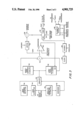
- FIG. 3 depicts those circuit blocks contained in controller 28 of FIG. 1 which operate on digital samples of the impedance measurement to derive pace commands for extension to pulse generator 18;
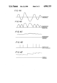
- FIG. 4 depicts several waveforms which will facilitate an understanding of the operation of the circuitry of FIG. 3.
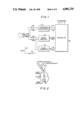
- FIG. 1 is a high-level block schematic. Tip and ring electrodes 10, 12 are those found in a conventional bipolar lead. All pacemaker logic is under control of controller 28 (which may include a microprocessor, although discrete blocks are shown in FIG. 3). The controller operates various switches in the pacemaker, of which only two pairs are shown. Switches S2a, S2b are closed whenever the pacemaker is to pace or sense. In order to pace, a command on PACE conductor 26 is generated by the controller, with pulse generator 18 then applying a current pulse through switches S2a, S2b to the tip and ring electrodes. Sense amplifier 16 senses a cardiac signal on the electrodes.
- the impedance measurement is made when controller 28 pulses conductor 20 and informs block 14 that a measurement is required. At this time switches S1a, S1b close, and switches S2a, S2b open. A current is applied to the ring electrode 12, with the current flowing through the ring and the case.
- the case is shown symbolically by the numeral 30, and it serves as a reference potential for the pacemaker circuitry.
- the blood impedance is measured by block 14 determining the potential between tip electrode 10 and the case. Samples are derived at the rate of 20 per second, and digital samples are extended over conductor 22 to controller 28.
- the impedance measurement can be effected as described in the above-identified Nappholz et al patent.
- the impedance measurement reflects minute volume to a much greater extent than stroke volume because of the characteristics of the filter which is part of the impedance measurement circuit (see FIG. 1 of the Nappholz et al patent).
- the impedance signal is filtered by a two-pole filter whose center frequency is at 0.2 Hz. The gain is reduced by a factor of two (6 dB) at frequencies of 0.05 Hz and 0.8 Hz.
- Absolute magnitude extractor 40 derives the absolute magnitude of each digital sample. This simply means that negative signs are changed to positive.
- the average value of the digital samples is zero. This is because the filter in the impedance measurement block has a gain of zero for a frequency of zero (DC).
- averager 42 derives a running average of the absolute magnitudes of the samples. The time constant of the averager is short so that the digital value at its output represents the average tidal volume over a few breaths. Adding the samples and averaging them provides a measure of the tidal volume because the absolute magnitudes represent the respiratory impedance signal.
- Sign extractor 44 looks only at the sign of each sample. Successive bits are delivered to zero crossing detector 46, the bits representing the signs of the samples. The function of the zero crossing detector is to establish when the polarity of the measurement signal has changed. Whenever this happens, sampler 48 is triggered and a sample is taken of the average value represented by averager 42. This sample is delivered to both short-term averager 50 and long-term averager 52.
- the zero crossing detector pulses its output twice during each breath, when the baseline is crossed during an exhalation and an inhalation. Thus two samples are taken for each breath. That is of no moment since what is desired are measurements which are representative of (proportional to) parameters of interest, not exact values. For such a scheme to work, it is important that the zero crossing detector function properly. Otherwise, too many or too few samples will be taken and the two averages derived by blocks 50 and 52 will not be accurate representations of short-term and long-term measurements. A type of "majority vote" technique is used to sense a zero crossing.
- each average value sample at the output of averager 42 represents the average of the last few integrals of the respiratory impedance signal, i.e., tidal volume.
- FIGS. 4A-4E depict the operation of the circuitry on the left side of FIG. 3.
- Waveform 4A is the respiratory impedance signal itself. The peak-to-peak amplitudes correspond to tidal volume.
- Waveform 4B shows the effect of rectifying the signal, that is, the effect of taking the absolute magnitude of the signal.
- Waveform 4C shows the average value, as a function of time, of the rectified impedance signal. Although such an analog signal is not developed in FIG. 3, averager 42 does derive a digital value which at any sampling time corresponds to the analog value shown in FIG. 4C.
- long-term averager 52 derives a value which represents minute volume as measured over an interval of about one hour.
- Short-term averager 50 derives a value which is based upon minute volume measurements during less than the last minute (e.g., 30 seconds).
- Summer 54 derives the difference between two signals, and it is represented in the drawing as delta MV. This is the control signal which drives the pacing rate. As the short-term average increases relative to the long-term average, representing metabolic demand, the pacing rate increases. Conversely, when the difference decreases, the pacing rate decreases.
- the delta MV value at any instant is applied to the input of limiter 56.
- the other input to limiter 56 is delta MVMAX, a quantity which will be described below but which serves as the maximum delta MV value which can control the escape interval of the pacemaker.
- the current value of delta MV, or delta MVMAX if it is smaller than delta MV, is applied to the minus input of summer 58.
- a quantity referred to as maximum interval is applied to the plus input of the summer.
- Maximum interval is an offset which corresponds to the minimum rate of the pacemaker, a quantity set by the physician.
- the difference is applied to the input of timer 62. The timer is loaded with the difference value when a load signal is derived on conductor 24 by the sense amplifier of the pacemaker.
- delta MV is transmitted from the pacemaker to a conventional type external programmer (not shown) for reasons to be described below.
- the programmer programs four values which are required in the operation of the circuitry of FIG. 3. (Other values, such as pulse amplitude, can be programmed, as is known in the art, but are not pertinent to the present invention.)
- the prescaler value is also derived from the programmer, and it is applied to an input of divider 66. It is apparent that the larger the value of prescaler, the slower the rate at which timer 62 is decremented, and the longer the escape interval.
- a third value which is derived from the programmer is delta MVMAX. This value corresponds to the maximum rate (another quantity which can be programmed in conventional pacemakers). How the several values are derived can only be understood by considering the overall programming procedure.
- the patient When a pacemaker is first implanted, the patient is put at rest for about one hour. A long-term average value of minute volume is derived by block 52 in the usual manner. The patient is then told to exercise until he is breathing at his peak rate. At this time the short-term average derived by block 50 will be at its maximum value for present conditions (those reflected in the long-term average). Thus the delta MV value at the output of summer 54 corresponds to the maximum control signal which will be used to control the pacing rate. It should be noted that in the short time that it takes the patient to get up to his peak exercising rate, the long-term value cannot change to any significant degree so that the delta MV value which is now derived indeed corresponds to peak metabolic demand.
- This value is telemetered out of the pacemaker, as shown at the bottom right of FIG. 3.
- the programmer measures the value and it is used as the delta MVMAX value which the programmer then telemeters back to the pacemaker.
- the value does not correspond to a maximum rate. It is simply the maximum value allowed for delta MV as an input to summer 58 during normal operation of the pacemaker. This is a form of runaway protection. Although there will be long-term changes, in the long run they will affect the short-term and long-term averages the same way, so the initially set value of delta MVMAX still applies no matter how the two average values are affected by long-term or permanent changes. (In the commercial Meta-MV pacemaker, the programmer can select from one of 60 values for delta MVMAX; it selects the one which is closest to the delta MV value which is telemetered out of the pacemaker during the set-up procedure.)
- Clock 64 operates at a 32-kHz rate.
- the value of the prescaler determines the rate at which timer 62 is decremented.
- the pacing rate is inversely proportional to the initial value loaded in timer 62.
- the pacing rate is also inversely proportional to the value of the prescaler because the larger the value, the less frequent the time-outs of timer 62.
- the prescaler value is the difference between the maximum interval and delta MVMAX because for the maximum rate, the output of the limiter should be at its maximum (which is delta MVMAX).
- the other equation defines the minimum rate.
- the minimum rate is equal to the same constant divided by two factors. One of these factors is again the prescaler, and the other is simply the maximum interval; the minimum rate is obtained when delta MV is zero and the output of limiter 56 is zero. There are thus two equations and two unknowns, and the physician, or the programmer, can solve for the two quantities maximum interval and prescaler. These quantities are telemetered to the pacemaker for storage and subsequent control of the pacemaker operation.
- maximum interval is not simply the inverse of the minimum rate.
- maximum interval is a quantity designed to provide minimum rate. But the actual value of that quantity depends on the solving of two equations for two unknowns. A physician may desire to provide the same minimum and maximum rates for two patients. During the set-up procedure, those two patients, when they are exercised, will have different delta MV values telemetered out of the pacemaker. The value telemetered out serves as the delta MVMAX value applied to limiter 56 in each case, and the two values are different. Since delta MVMAX is one input to summer 58, it is apparent that the quantity maximum interval must similarly be different for the two patients if they are to have the same minimum and maximum rates. It is the solution to two equations which allows the values maximum interval and prescaler to be derived for each patient.
- comparator 60 The only remaining element on FIG. 3 not described thus far is comparator 60.
- the value of delta MV is fed to the plus input of the comparator, and the minus input of the comparator is fed by a reference threshold.
- This reference threshold is the fourth value programmed during the set-up procedure. Whenever delta MV exceeds a reference threshold, the output of the comparator goes high and inhibits long-term averager 52. What happens, in effect, is that a large value of delta MV is assumed to represent exercise. Until the patient stops exercising, the long-term average is not increased. Were it allowed to increase, after an hour or so it would approach the short-term average. As the long-term average increased, delta MV would keep getting smaller and the pacing rate would drop from its initial high value.
- the reference threshold is equal to one-half of delta MVMAX.
- the 50% level is not fixed, however, and can be programmed differently if desired by the physician.
- the general technique allows long-term adaptation to the minute volume measurement baseline while still allowing extended periods of exercise.
- the threshold is midway between the minimum and maximum rates; in other words, if delta MV increases to the value which corresponds to the mid-range rate, the long-term average is frozen until delta MV drops below the mid-range value.
Abstract
Description
Claims (19)
Priority Applications (7)
| Application Number | Priority Date | Filing Date | Title |
|---|---|---|---|
| US07/150,038 US4901725A (en) | 1988-01-29 | 1988-01-29 | Minute volume rate-responsive pacemaker |
| AU28745/89A AU611250B2 (en) | 1988-01-29 | 1989-01-24 | Minute volume rate-responsive pacemaker |
| JP1016541A JPH01223977A (en) | 1988-01-29 | 1989-01-27 | Small volume speed response type pacemaker |
| EP93110579A EP0582087B1 (en) | 1988-01-29 | 1989-01-30 | Minute volume rate-responsive pacemaker |
| EP89300895A EP0327292B2 (en) | 1988-01-29 | 1989-01-30 | Minute volume rate-responsive pacemaker |
| DE68917166T DE68917166T3 (en) | 1988-01-29 | 1989-01-30 | Pacemaker controlled by the minute volume in its pulse rate. |
| DE68925591T DE68925591T2 (en) | 1988-01-29 | 1989-01-30 | Pacemaker in which the frequency depends on the cardiac output |
Applications Claiming Priority (1)
| Application Number | Priority Date | Filing Date | Title |
|---|---|---|---|
| US07/150,038 US4901725A (en) | 1988-01-29 | 1988-01-29 | Minute volume rate-responsive pacemaker |
Publications (1)
| Publication Number | Publication Date |
|---|---|
| US4901725A true US4901725A (en) | 1990-02-20 |
Family
ID=22532846
Family Applications (1)
| Application Number | Title | Priority Date | Filing Date |
|---|---|---|---|
| US07/150,038 Expired - Lifetime US4901725A (en) | 1988-01-29 | 1988-01-29 | Minute volume rate-responsive pacemaker |
Country Status (5)
| Country | Link |
|---|---|
| US (1) | US4901725A (en) |
| EP (2) | EP0327292B2 (en) |
| JP (1) | JPH01223977A (en) |
| AU (1) | AU611250B2 (en) |
| DE (2) | DE68917166T3 (en) |
Cited By (147)
| Publication number | Priority date | Publication date | Assignee | Title |
|---|---|---|---|---|
| US5003976A (en) * | 1987-09-28 | 1991-04-02 | Eckhard Alt | Cardiac and pulmonary physiological analysis via intracardiac measurements with a single sensor |
| US5036849A (en) * | 1990-04-04 | 1991-08-06 | Cardiac Pacemakers, Inc. | Variable rate cardiac pacer |
| US5048522A (en) * | 1990-04-13 | 1991-09-17 | Therapeutic Technologies, Inc. | Power muscle stimulator |
| US5078678A (en) * | 1990-03-02 | 1992-01-07 | Jefferson Katims | Method and apparatus for locating a catheter adjacent to a pacemaker node of the heart |
| US5083563A (en) * | 1990-02-16 | 1992-01-28 | Telectronics Pacing Systems, Inc. | Implantable automatic and haemodynamically responsive cardioverting/defibrillating pacemaker |
| US5085215A (en) * | 1990-03-20 | 1992-02-04 | Telectronics Pacing Systems, Inc. | Metabolic demand driven rate-responsive pacemaker |
| US5121750A (en) * | 1990-03-02 | 1992-06-16 | Katims Jefferson J | Apparatus for locating a catheter adjacent to a pacemaker node of the heart |
| US5137019A (en) * | 1990-03-08 | 1992-08-11 | Cardiac Pacemakers, Inc. | Variation in cardiac chamber volume or pressure as a controlling parameter |
| US5139020A (en) * | 1991-03-08 | 1992-08-18 | Telectronics Pacing Systems, Inc. | Method and apparatus for controlling the hemodynamic state of a patient based on systolic time interval measurements detecting using doppler ultrasound techniques |
| US5156154A (en) * | 1991-03-08 | 1992-10-20 | Telectronics Pacing Systems, Inc. | Monitoring the hemodynamic state of a patient from measurements of myocardial contractility using doppler ultrasound techniques |
| US5156157A (en) * | 1991-03-08 | 1992-10-20 | Telectronics Pacing Systems, Inc. | Catheter-mounted doppler ultrasound transducer and signal processor |
| US5156147A (en) * | 1991-02-05 | 1992-10-20 | Cardiac Pacemakers, Inc. | Variable rate pacemaker having upper rate limit governor based on hemodynamic performance |
| EP0510456A1 (en) * | 1991-04-26 | 1992-10-28 | Pacesetter AB | Implantable medical apparatus |
| US5161527A (en) * | 1991-02-13 | 1992-11-10 | Telectronics Pacing Systems, Inc. | Apparatus and method for detecting abnormal cardiac rhythms in dual chamber arrhythmia control system |
| US5183040A (en) * | 1991-03-08 | 1993-02-02 | Telectronics Pacing Systems, Inc. | Apparatus and method for detecting abnormal cardiac rhythms using an ultrasound sensor in an arrhythmia control system |
| US5188106A (en) * | 1991-03-08 | 1993-02-23 | Telectronics Pacing Systems, Inc. | Method and apparatus for chronically monitoring the hemodynamic state of a patient using doppler ultrasound |
| US5197467A (en) * | 1992-06-22 | 1993-03-30 | Telectronics Pacing Systems, Inc. | Multiple parameter rate-responsive cardiac stimulation apparatus |
| US5201808A (en) * | 1992-02-10 | 1993-04-13 | Telectronics Pacing Systems, Inc. | Minute volume rate-responsive pacemaker employing impedance sensing on a unipolar lead |
| US5246008A (en) * | 1991-01-11 | 1993-09-21 | Guido Fehling | Method for monitoring a patient for rejection reactions to an implanted heart |
| WO1993018821A1 (en) * | 1992-03-26 | 1993-09-30 | Medtronic, Inc. | Multiple frequency impedance measurement for physiological monitoring of the condition of a patient's body tissue |
| US5249572A (en) * | 1990-12-27 | 1993-10-05 | Ela Medical | Method and apparatus for controlling the pacing rate of a metabolic demand pacemaker |
| US5284136A (en) * | 1990-04-04 | 1994-02-08 | Cardiac Pacemakers, Inc. | Dual indifferent electrode pacemaker |
| US5292340A (en) * | 1993-01-04 | 1994-03-08 | Telectronics Pacing Systems, Inc. | Physiologically-calibrated rate adaptive, dual chamber pacemaker |
| US5300093A (en) * | 1992-09-14 | 1994-04-05 | Telectronics Pacing Systems, Inc. | Apparatus and method for measuring, formatting and transmitting combined intracardiac impedance data and electrograms |
| US5303702A (en) * | 1990-12-27 | 1994-04-19 | Ela Medical | Automatic adjustment of the control function for a rate adaptive pacemaker |
| US5312445A (en) * | 1992-02-03 | 1994-05-17 | Telectronics Pacing Systems, Inc. | Implantable cardiac stimulating apparatus and method employing detection of P-waves from signals sensed in the ventricle |
| US5314449A (en) * | 1992-02-26 | 1994-05-24 | Siemens Aktiengesellschaft | Rate-adaptive cardiac pacemaker |
| US5355894A (en) * | 1992-08-26 | 1994-10-18 | Siemens Aktiengesellschaft | Method for generating a signal corresponding to the respiration volume per unit of time of a patient |
| US5361776A (en) * | 1993-08-06 | 1994-11-08 | Telectronics Pacing Systems, Inc. | Time domain reflectometer impedance sensor method of use and implantable cardiac stimulator using same |
| US5365932A (en) * | 1993-09-02 | 1994-11-22 | Telectronics Pacing System, Inc. | Cardiac signal sensing device having sensitivity automatically controlled in response to metabolic demand |
| US5404877A (en) * | 1993-06-04 | 1995-04-11 | Telectronics Pacing Systems, Inc. | Leadless implantable sensor assembly and a cardiac emergency warning alarm |
| US5431692A (en) * | 1993-08-02 | 1995-07-11 | Telectronics Pacing Systems, Inc. | Method and apparatus for testing compatibility of lead polarity and polarity programming of a cardiac stimulator |
| US5441523A (en) * | 1994-04-12 | 1995-08-15 | Telectronics Pacing Systems, Inc. | Forced atrioventricular synchrony dual chamber pacemaker |
| US5487753A (en) * | 1995-03-16 | 1996-01-30 | Telectronics Pacing Systems, Inc. | Rate-responsive pacemaker with anaerobic threshold adaptation and method |
| EP0702980A2 (en) | 1994-09-21 | 1996-03-27 | Telectronics N.V. | Dual sensor rate responsive pacemaker |
| US5507785A (en) * | 1994-12-21 | 1996-04-16 | Intermedics, Inc. | Rate responsive cardiac pacemaker with biphasic impedance sensing and method |
| US5531772A (en) * | 1994-11-18 | 1996-07-02 | Intermedics, Inc. | Rate responsive cardiac pacemaker with filtered impedance sensing and method |
| US5534018A (en) * | 1994-11-30 | 1996-07-09 | Medtronic, Inc. | Automatic lead recognition for implantable medical device |
| US5562712A (en) * | 1994-11-25 | 1996-10-08 | Dow Corning Corporation | Minute volume rate-responsive pacemaker using dual unipolar leads |
| US5578064A (en) * | 1994-08-11 | 1996-11-26 | Intermedics, Inc. | Rate responsive cardiac pacemaker with impedance sensing |
| US5643327A (en) * | 1995-06-20 | 1997-07-01 | Pacesetter, Inc. | Pacemaker and method having optimized A-V delay by using the evoked depolarization potential as an indicia of cardiac output |
| EP0788812A1 (en) * | 1996-02-12 | 1997-08-13 | Pacesetter AB | Pacemaker system comprising a bipolar sensor electrode |
| US5707398A (en) * | 1996-11-12 | 1998-01-13 | Pacesetter, Inc. | Automatic determination of optimum electrode configuration for a cardiac stimulator |
| US5709709A (en) * | 1996-02-13 | 1998-01-20 | Angeion Corporation | ICD with rate-responsive pacing |
| US5718720A (en) * | 1996-12-13 | 1998-02-17 | Sulzer Intermedics Inc. | Implantable cardiac stimulator with capture detection and impedance based autotuning of capture detection |
| US5720770A (en) * | 1995-10-06 | 1998-02-24 | Pacesetter, Inc. | Cardiac stimulation system with enhanced communication and control capability |
| US5720295A (en) * | 1996-10-15 | 1998-02-24 | Pacesetter, Inc. | Pacemaker with improved detection of atrial fibrillation |
| EP0824937A2 (en) | 1996-08-22 | 1998-02-25 | Pacesetter, Inc. | Pacemaker with improved distributed rate pacing |
| EP0830877A2 (en) | 1996-09-20 | 1998-03-25 | Pacesetter, Inc. | Pacemaker with safety pacing |
| US5735883A (en) * | 1996-12-13 | 1998-04-07 | Sulzer Intermedics Inc. | Implantable cardiac stimulator with impedance based autothreshold |
| WO1998019737A1 (en) | 1996-11-05 | 1998-05-14 | Intermedics Inc. | Rate responsive cardiac pacemaker with peak impedance detection for rate control |
| US5792196A (en) * | 1996-04-30 | 1998-08-11 | Cooper; Daniel | Rate-responsive pacemaker with automatic rate response factor selection |
| US5792192A (en) * | 1997-04-19 | 1998-08-11 | Lu; Richard | Pacemaker with automatic mode switching using detection of hidden intrinsic cardiac pulses |
| US5800469A (en) * | 1997-04-16 | 1998-09-01 | Nappholz; Tibor A. | Pacemaker with anaerobic threshold determination |
| US5817135A (en) * | 1997-05-02 | 1998-10-06 | Pacesetter, Inc. | Rate-responsive pacemaker with noise-rejecting minute volume determination |
| US5817136A (en) * | 1997-05-02 | 1998-10-06 | Pacesetter, Inc. | Rate-responsive pacemaker with minute volume determination and EMI protection |
| US5824020A (en) * | 1997-05-02 | 1998-10-20 | Pacesetter, Inc. | Rate-responsive pacemaker with rapid minute volume determination |
| US5836988A (en) * | 1997-05-02 | 1998-11-17 | Pacesetter, Inc. | Rate responsive pacemaker with exercise recovery using minute volume determination |
| EP0904802A2 (en) | 1997-08-29 | 1999-03-31 | Pacesetter, Inc. | Apparatus for preventing development of atrial fibrillation |
| US5964788A (en) * | 1997-10-28 | 1999-10-12 | Pacesetter, Inc. | Method and apparatus for controlling a pacemaker using respiration |
| US6044294A (en) * | 1995-12-15 | 2000-03-28 | Pacesetter, Inc. | Methods and apparatus for measuring impedance in the body |
| US6076015A (en) * | 1998-02-27 | 2000-06-13 | Cardiac Pacemakers, Inc. | Rate adaptive cardiac rhythm management device using transthoracic impedance |
| US6126611A (en) * | 1998-02-04 | 2000-10-03 | Medtronic, Inc. | Apparatus for management of sleep apnea |
| WO2001023040A1 (en) | 1999-09-30 | 2001-04-05 | Uab Research Foundation | Method of determining a ventilatory threshold breakpoint for an adaptive rate pacemaker |
| US6269264B1 (en) * | 1996-12-13 | 2001-07-31 | Pacesetter, Inc. | Method for measuring impedance in the body |
| US6299582B1 (en) | 1995-09-28 | 2001-10-09 | Data Sciences International, Inc. | Respiration monitoring system based on sensed blood pressure variations |
| US6334071B1 (en) | 1999-06-07 | 2001-12-25 | Pacesetter, Inc. | Minute volume pacemakers that require only a single distal electrode |
| US6350242B1 (en) | 1995-09-28 | 2002-02-26 | Data Sciences International, Inc. | Respiration monitoring system based on sensed physiological parameters |
| US6360123B1 (en) | 1999-08-24 | 2002-03-19 | Impulse Dynamics N.V. | Apparatus and method for determining a mechanical property of an organ or body cavity by impedance determination |
| US20020169484A1 (en) * | 2001-02-13 | 2002-11-14 | Scott Mathis | Multi-electrode apparatus and method for treatment of congestive heart failure |
| US6484057B2 (en) | 2000-12-21 | 2002-11-19 | Uab Research Foundation | Pacing methods and devices for treating cardiac arrhythmias and fibrillation |
| US20030086505A1 (en) * | 1999-01-11 | 2003-05-08 | Nguyen Luu V. | Phase shift key burst receiver having improved phase resolution and timing and data recovery |
| US20030114889A1 (en) * | 2000-07-14 | 2003-06-19 | Cardiac Pacemakers, Inc. | Method and apparatuses for monitoring hemodynamic activities using an intracardiac impedance-derived parameter |
| US20030204212A1 (en) * | 2002-04-29 | 2003-10-30 | Burnes John E. | Algorithm for the automatic determination of optimal AV and VV intervals |
| US6645153B2 (en) | 2002-02-07 | 2003-11-11 | Pacesetter, Inc. | System and method for evaluating risk of mortality due to congestive heart failure using physiologic sensors |
| US20040006375A1 (en) * | 2002-02-15 | 2004-01-08 | Yann Poezevera | Detection and the treatment of ventilatory disorders during sleep for an active implantable medical device, in particular a pacemaker |
| US20040024421A1 (en) * | 2002-07-31 | 2004-02-05 | Ideker Raymond E. | Pacing methods and devices using feedback controlled timing |
| US20040049237A1 (en) * | 2002-07-12 | 2004-03-11 | Larson Dennis E. | Minute ventilation sensor with dynamically adjusted excitation current |
| US20040049118A1 (en) * | 2002-09-10 | 2004-03-11 | Ideker Raymond E. | Methods, systems and computer program products for treating fibrillation in a patient based on the presence of fibrillation following administration of defibrillation therapy |
| US20040049232A1 (en) * | 2002-09-10 | 2004-03-11 | Ideker Raymond E. | Post-defibrillation pacing methods and devices |
| US20040049117A1 (en) * | 2002-09-10 | 2004-03-11 | Ideker Raymond E. | Devices for detecting the presence of cardiac activity following administration of defibrillation therapy |
| US6741885B1 (en) | 2000-12-07 | 2004-05-25 | Pacesetter, Inc. | Implantable cardiac device for managing the progression of heart disease and method |
| US20040102908A1 (en) * | 2002-11-27 | 2004-05-27 | Larson Dennis E. | Minute ventilation sensor with automatic high pass filter adjustment |
| US20040116820A1 (en) * | 2002-12-13 | 2004-06-17 | Daum Douglas R. | Respiration signal measurement apparatus, systems, and methods |
| US20040138716A1 (en) * | 2003-01-10 | 2004-07-15 | Steve Kon | System and method for detecting circadian states using an implantable medical device |
| US20050004610A1 (en) * | 2003-07-02 | 2005-01-06 | Jaeho Kim | Cardiac cycle synchronized sampling of impedance signal |
| US20050055060A1 (en) * | 2003-09-05 | 2005-03-10 | Steve Koh | Determination of respiratory characteristics from AV conduction intervals |
| US20050075672A1 (en) * | 2003-10-06 | 2005-04-07 | Rottenberg William B. | Cardiac Stimulation Apparatus With Multiple Input Sense Amplifiers |
| US20050080460A1 (en) * | 2003-10-14 | 2005-04-14 | Li Wang | Method and apparatus for monitoring tissue fluid content for use in an implantable cardiac device |
| US20050119711A1 (en) * | 2003-01-10 | 2005-06-02 | Cho Yong K. | Apparatus and method for monitoring for disordered breathing |
| US6961615B2 (en) | 2002-02-07 | 2005-11-01 | Pacesetter, Inc. | System and method for evaluating risk of mortality due to congestive heart failure using physiologic sensors |
| US20060025661A1 (en) * | 2004-08-02 | 2006-02-02 | Sweeney Robert J | Device for monitoring fluid status |
| US20060155334A1 (en) * | 2003-03-13 | 2006-07-13 | Ideker Raymond E | Methods and systems for reducing discomfort from cardiac defibrillation shocks |
| US7136705B1 (en) | 2002-05-31 | 2006-11-14 | Pacesetter, Inc. | Method and apparatus for monitoring sensor performance during rate-responsive cardiac stimulation |
| US20070060833A1 (en) * | 2005-09-15 | 2007-03-15 | Hauck John A | Method of scaling navigation signals to account for impedance drift in tissue |
| US7308311B2 (en) | 2002-11-22 | 2007-12-11 | Pacesetter, Inc. | Physician programmer system with telemetered sensor waveform |
| US20080097232A1 (en) * | 2006-10-23 | 2008-04-24 | Rothenberg Peter M | Method of locating the tip of a central venous catheter |
| US20080294060A1 (en) * | 2007-05-21 | 2008-11-27 | Cardiac Pacemakers, Inc. | Devices and methods for disease detection, monitoring and/or management |
| US7524292B2 (en) | 2003-04-21 | 2009-04-28 | Medtronic, Inc. | Method and apparatus for detecting respiratory disturbances |
| US20090156926A1 (en) * | 2007-11-26 | 2009-06-18 | C.R. Bard, Inc. | Integrated System for Intravascular Placement of a Catheter |
| US20090203989A1 (en) * | 2008-02-11 | 2009-08-13 | C. R. Bard, Inc. | Systems and methods for positioning a catheter |
| US20090234328A1 (en) * | 2007-11-26 | 2009-09-17 | C.R. Bard, Inc. | Systems and methods for breaching a sterile field for intravascular placement of a catheter |
| US20090259124A1 (en) * | 2006-10-23 | 2009-10-15 | Rothenberg Peter M | Method of locating the tip of a central venous catheter |
| US20100094116A1 (en) * | 2008-10-07 | 2010-04-15 | Lucent Medical Systems, Inc. | Percutaneous magnetic gastrostomy |
| US20100100000A1 (en) * | 2008-09-24 | 2010-04-22 | Kent Lee | Minute Ventilation-Based Disordered Breathing Detection |
| US7734344B2 (en) | 2003-12-02 | 2010-06-08 | Uab Research Foundation | Methods, systems and computer program products to inhibit ventricular fibrillation during cardiopulmonary resuscitation |
| US20100179421A1 (en) * | 2007-05-24 | 2010-07-15 | Joe Tupin | System and method for non-invasive instantaneous and continuous measurement of cardiac chamber volume. |
| US20100222664A1 (en) * | 2008-08-22 | 2010-09-02 | C. R. Bard. Inc. | Catheter assembly including ecg sensor and magnetic assemblies |
| US20100234720A1 (en) * | 2003-06-04 | 2010-09-16 | Tupin Jr Joe Paul | System and method for extracting physiological data using ultra-wideband radar and improved signal processing techniques |
| US20100318026A1 (en) * | 2009-06-12 | 2010-12-16 | Romedex International Srl | Devices and Methods for Endovascular Electrography |
| US20110060215A1 (en) * | 2009-03-30 | 2011-03-10 | Tupin Jr Joe Paul | Apparatus and method for continuous noninvasive measurement of respiratory function and events |
| US20110196248A1 (en) * | 2009-06-12 | 2011-08-11 | Bard Access Systems, Inc. | Apparatus and method for catheter navigation and tip location |
| US8050764B2 (en) | 2003-10-29 | 2011-11-01 | Cardiac Pacemakers, Inc. | Cross-checking of transthoracic impedance and acceleration signals |
| US20120035496A1 (en) * | 2009-04-24 | 2012-02-09 | Denison Timothy J | Bladder sensing using impedance and posture |
| US8209011B2 (en) | 2002-12-30 | 2012-06-26 | Cardiac Pacemakers, Inc. | Automatically configurable minute ventilation sensor |
| US20130041204A1 (en) * | 2011-02-18 | 2013-02-14 | Marlin Stephen Heilman | Control of blood flow assist systems |
| US20130090707A1 (en) * | 2011-10-06 | 2013-04-11 | Thomas Doerr | Temperature sensor for an implantable medical apparatus |
| US8478413B2 (en) | 2011-07-27 | 2013-07-02 | Medtronic, Inc. | Bilateral phrenic nerve stimulation with reduced dyssynchrony |
| USD699359S1 (en) | 2011-08-09 | 2014-02-11 | C. R. Bard, Inc. | Ultrasound probe head |
| US8706235B2 (en) | 2011-07-27 | 2014-04-22 | Medtronic, Inc. | Transvenous method to induce respiration |
| US8781555B2 (en) | 2007-11-26 | 2014-07-15 | C. R. Bard, Inc. | System for placement of a catheter including a signal-generating stylet |
| US8784336B2 (en) | 2005-08-24 | 2014-07-22 | C. R. Bard, Inc. | Stylet apparatuses and methods of manufacture |
| US8801693B2 (en) | 2010-10-29 | 2014-08-12 | C. R. Bard, Inc. | Bioimpedance-assisted placement of a medical device |
| US8849382B2 (en) | 2007-11-26 | 2014-09-30 | C. R. Bard, Inc. | Apparatus and display methods relating to intravascular placement of a catheter |
| US8897879B2 (en) | 2011-11-04 | 2014-11-25 | Medtronic, Inc. | Method and apparatus for therapies of the cardiovascular and cardiorenal system |
| USD724745S1 (en) | 2011-08-09 | 2015-03-17 | C. R. Bard, Inc. | Cap for an ultrasound probe |
| US9078582B2 (en) | 2009-04-22 | 2015-07-14 | Lifewave Biomedical, Inc. | Fetal monitoring device and methods |
| US9211107B2 (en) | 2011-11-07 | 2015-12-15 | C. R. Bard, Inc. | Ruggedized ultrasound hydrogel insert |
| US9339206B2 (en) | 2009-06-12 | 2016-05-17 | Bard Access Systems, Inc. | Adaptor for endovascular electrocardiography |
| US9456766B2 (en) | 2007-11-26 | 2016-10-04 | C. R. Bard, Inc. | Apparatus for use with needle insertion guidance system |
| US9492097B2 (en) | 2007-11-26 | 2016-11-15 | C. R. Bard, Inc. | Needle length determination and calibration for insertion guidance system |
| US9521961B2 (en) | 2007-11-26 | 2016-12-20 | C. R. Bard, Inc. | Systems and methods for guiding a medical instrument |
| US9532724B2 (en) | 2009-06-12 | 2017-01-03 | Bard Access Systems, Inc. | Apparatus and method for catheter navigation using endovascular energy mapping |
| US9554716B2 (en) | 2007-11-26 | 2017-01-31 | C. R. Bard, Inc. | Insertion guidance system for needles and medical components |
| US9636031B2 (en) | 2007-11-26 | 2017-05-02 | C.R. Bard, Inc. | Stylets for use with apparatus for intravascular placement of a catheter |
| US9839372B2 (en) | 2014-02-06 | 2017-12-12 | C. R. Bard, Inc. | Systems and methods for guidance and placement of an intravascular device |
| US10046139B2 (en) | 2010-08-20 | 2018-08-14 | C. R. Bard, Inc. | Reconfirmation of ECG-assisted catheter tip placement |
| US10349890B2 (en) | 2015-06-26 | 2019-07-16 | C. R. Bard, Inc. | Connector interface for ECG-based catheter positioning system |
| US10449330B2 (en) | 2007-11-26 | 2019-10-22 | C. R. Bard, Inc. | Magnetic element-equipped needle assemblies |
| US10524691B2 (en) | 2007-11-26 | 2020-01-07 | C. R. Bard, Inc. | Needle assembly including an aligned magnetic element |
| US10639008B2 (en) | 2009-10-08 | 2020-05-05 | C. R. Bard, Inc. | Support and cover structures for an ultrasound probe head |
| US10751509B2 (en) | 2007-11-26 | 2020-08-25 | C. R. Bard, Inc. | Iconic representations for guidance of an indwelling medical device |
| US10820885B2 (en) | 2012-06-15 | 2020-11-03 | C. R. Bard, Inc. | Apparatus and methods for detection of a removable cap on an ultrasound probe |
| US10973584B2 (en) | 2015-01-19 | 2021-04-13 | Bard Access Systems, Inc. | Device and method for vascular access |
| US10992079B2 (en) | 2018-10-16 | 2021-04-27 | Bard Access Systems, Inc. | Safety-equipped connection systems and methods thereof for establishing electrical connections |
| US11000207B2 (en) | 2016-01-29 | 2021-05-11 | C. R. Bard, Inc. | Multiple coil system for tracking a medical device |
| US11103213B2 (en) | 2009-10-08 | 2021-08-31 | C. R. Bard, Inc. | Spacers for use with an ultrasound probe |
Families Citing this family (6)
| Publication number | Priority date | Publication date | Assignee | Title |
|---|---|---|---|---|
| US5500006A (en) * | 1990-10-04 | 1996-03-19 | Pacesetter Ab | Arrangement, particularly a heart pacemarker, for acquiring a measurement parameter of the heart activity |
| US5271395A (en) * | 1992-04-17 | 1993-12-21 | Medtronic, Inc. | Method and apparatus for rate-responsive cardiac pacing |
| DE4231601A1 (en) * | 1992-09-17 | 1994-03-24 | Biotronik Mess & Therapieg | Arrangement for controlling a pacemaker |
| DE4231602B4 (en) * | 1992-09-17 | 2004-11-04 | Biotronik Meß- und Therapiegeräte GmbH & Co. Ingenieurbüro Berlin | Circuit for measuring the impedance in the heart |
| US5524632A (en) * | 1994-01-07 | 1996-06-11 | Medtronic, Inc. | Method for implanting electromyographic sensing electrodes |
| JP5117634B2 (en) | 2009-05-26 | 2013-01-16 | カーディアック ペースメイカーズ, インコーポレイテッド | Normalization and calculation of ventilation sensor rate response |
Citations (15)
| Publication number | Priority date | Publication date | Assignee | Title |
|---|---|---|---|---|
| AT34303B (en) | 1907-03-26 | 1908-09-10 | Philipp Dr Goldstern | Process for the extraction of solid, odorless bodies from the alkaline liquids that fall off during the refining of the mineral lubricating oils. |
| US4440177A (en) * | 1980-07-03 | 1984-04-03 | Medical Graphics Corporation | Respiratory analyzer system |
| US4444201A (en) * | 1980-08-27 | 1984-04-24 | Tokyo Shibaura Denki Kabushiki Kaisha | Respiration monitoring apparatus and method |
| US4513752A (en) * | 1983-01-17 | 1985-04-30 | Pacesetter Systems, Inc. | Bipolar sensing system |
| EP0140472A1 (en) * | 1983-06-30 | 1985-05-08 | Medtronic, Inc. | Stroke volume controlled pacer |
| US4585004A (en) * | 1984-06-01 | 1986-04-29 | Cardiac Control Systems, Inc. | Heart pacing and intracardiac electrogram monitoring system and associated method |
| US4596251A (en) * | 1984-02-07 | 1986-06-24 | Gianni Plicchi | Minute ventilation dependent rate responsive pacer |
| EP0228985A1 (en) * | 1985-09-18 | 1987-07-15 | BIOTRONIK Mess- und Therapiegeräte GmbH & Co Ingenieurbüro Berlin | Heart pacemaker |
| US4702253A (en) * | 1985-10-15 | 1987-10-27 | Telectronics N.V. | Metabolic-demand pacemaker and method of using the same to determine minute volume |
| EP0249821A1 (en) * | 1986-06-16 | 1987-12-23 | Pacesetter AB | A cardiac pacer for pacing a heart |
| US4721110A (en) * | 1984-08-06 | 1988-01-26 | Lampadius Michael S | Respiration-controlled cardiac pacemaker |
| US4730618A (en) * | 1986-06-16 | 1988-03-15 | Siemens Aktiengesellschaft | Cardiac pacer for pacing a human heart and pacing method |
| US4730619A (en) * | 1985-04-11 | 1988-03-15 | Telectronics, N.V. | Apparatus and method for adjusting heart/pacer rate relative to ejection time to obtain a required cardiac output |
| ATE34303T1 (en) * | 1982-03-16 | 1988-06-15 | Gianni Plicchi | PHYSIOLOGICAL IMPLANTABLE PACEMAKER WHICH STIMULATION RATE IS CONTROLLED BY THE PATIENT'S RESPIRATORY RATE. |
| US4757815A (en) * | 1985-12-20 | 1988-07-19 | Siemens Aktiengesellschaft | Heart pacemaker |
Family Cites Families (2)
| Publication number | Priority date | Publication date | Assignee | Title |
|---|---|---|---|---|
| EP0215731B1 (en) * | 1985-09-17 | 1992-12-30 | BIOTRONIK Mess- und Therapiegeräte GmbH & Co Ingenieurbüro Berlin | Heart stimulator |
| DE3650261D1 (en) * | 1985-09-17 | 1995-04-13 | Biotronik Mess & Therapieg | Pacemaker. |
-
1988
- 1988-01-29 US US07/150,038 patent/US4901725A/en not_active Expired - Lifetime
-
1989
- 1989-01-24 AU AU28745/89A patent/AU611250B2/en not_active Ceased
- 1989-01-27 JP JP1016541A patent/JPH01223977A/en active Pending
- 1989-01-30 EP EP89300895A patent/EP0327292B2/en not_active Expired - Lifetime
- 1989-01-30 EP EP93110579A patent/EP0582087B1/en not_active Expired - Lifetime
- 1989-01-30 DE DE68917166T patent/DE68917166T3/en not_active Expired - Fee Related
- 1989-01-30 DE DE68925591T patent/DE68925591T2/en not_active Expired - Fee Related
Patent Citations (15)
| Publication number | Priority date | Publication date | Assignee | Title |
|---|---|---|---|---|
| AT34303B (en) | 1907-03-26 | 1908-09-10 | Philipp Dr Goldstern | Process for the extraction of solid, odorless bodies from the alkaline liquids that fall off during the refining of the mineral lubricating oils. |
| US4440177A (en) * | 1980-07-03 | 1984-04-03 | Medical Graphics Corporation | Respiratory analyzer system |
| US4444201A (en) * | 1980-08-27 | 1984-04-24 | Tokyo Shibaura Denki Kabushiki Kaisha | Respiration monitoring apparatus and method |
| ATE34303T1 (en) * | 1982-03-16 | 1988-06-15 | Gianni Plicchi | PHYSIOLOGICAL IMPLANTABLE PACEMAKER WHICH STIMULATION RATE IS CONTROLLED BY THE PATIENT'S RESPIRATORY RATE. |
| US4513752A (en) * | 1983-01-17 | 1985-04-30 | Pacesetter Systems, Inc. | Bipolar sensing system |
| EP0140472A1 (en) * | 1983-06-30 | 1985-05-08 | Medtronic, Inc. | Stroke volume controlled pacer |
| US4596251A (en) * | 1984-02-07 | 1986-06-24 | Gianni Plicchi | Minute ventilation dependent rate responsive pacer |
| US4585004A (en) * | 1984-06-01 | 1986-04-29 | Cardiac Control Systems, Inc. | Heart pacing and intracardiac electrogram monitoring system and associated method |
| US4721110A (en) * | 1984-08-06 | 1988-01-26 | Lampadius Michael S | Respiration-controlled cardiac pacemaker |
| US4730619A (en) * | 1985-04-11 | 1988-03-15 | Telectronics, N.V. | Apparatus and method for adjusting heart/pacer rate relative to ejection time to obtain a required cardiac output |
| EP0228985A1 (en) * | 1985-09-18 | 1987-07-15 | BIOTRONIK Mess- und Therapiegeräte GmbH & Co Ingenieurbüro Berlin | Heart pacemaker |
| US4702253A (en) * | 1985-10-15 | 1987-10-27 | Telectronics N.V. | Metabolic-demand pacemaker and method of using the same to determine minute volume |
| US4757815A (en) * | 1985-12-20 | 1988-07-19 | Siemens Aktiengesellschaft | Heart pacemaker |
| EP0249821A1 (en) * | 1986-06-16 | 1987-12-23 | Pacesetter AB | A cardiac pacer for pacing a heart |
| US4730618A (en) * | 1986-06-16 | 1988-03-15 | Siemens Aktiengesellschaft | Cardiac pacer for pacing a human heart and pacing method |
Non-Patent Citations (2)
| Title |
|---|
| A. Barker et al., "Single Impedance Pneumograph and Volume Integrator" Technical Note Medical and Biological Engineering, May, 1973, pp. 352-353. |
| A. Barker et al., Single Impedance Pneumograph and Volume Integrator Technical Note Medical and Biological Engineering, May, 1973, pp. 352 353. * |
Cited By (250)
| Publication number | Priority date | Publication date | Assignee | Title |
|---|---|---|---|---|
| US5003976A (en) * | 1987-09-28 | 1991-04-02 | Eckhard Alt | Cardiac and pulmonary physiological analysis via intracardiac measurements with a single sensor |
| US5083563A (en) * | 1990-02-16 | 1992-01-28 | Telectronics Pacing Systems, Inc. | Implantable automatic and haemodynamically responsive cardioverting/defibrillating pacemaker |
| US5121750A (en) * | 1990-03-02 | 1992-06-16 | Katims Jefferson J | Apparatus for locating a catheter adjacent to a pacemaker node of the heart |
| WO1993008731A1 (en) * | 1990-03-02 | 1993-05-13 | Katims Jefferson J | Method and apparatus for locating a catheter |
| US5078678A (en) * | 1990-03-02 | 1992-01-07 | Jefferson Katims | Method and apparatus for locating a catheter adjacent to a pacemaker node of the heart |
| US5391190A (en) * | 1990-03-08 | 1995-02-21 | Cardiac Pacemakers, Inc. | Variation in cardiac chamber volume or pressure as a controlling parameter |
| US5137019A (en) * | 1990-03-08 | 1992-08-11 | Cardiac Pacemakers, Inc. | Variation in cardiac chamber volume or pressure as a controlling parameter |
| US5085215A (en) * | 1990-03-20 | 1992-02-04 | Telectronics Pacing Systems, Inc. | Metabolic demand driven rate-responsive pacemaker |
| AU630319B2 (en) * | 1990-03-20 | 1992-10-22 | Telectronics N.V. | Metabolic demand driven rate-responsive pacemaker |
| US5036849A (en) * | 1990-04-04 | 1991-08-06 | Cardiac Pacemakers, Inc. | Variable rate cardiac pacer |
| US5284136A (en) * | 1990-04-04 | 1994-02-08 | Cardiac Pacemakers, Inc. | Dual indifferent electrode pacemaker |
| US5048522A (en) * | 1990-04-13 | 1991-09-17 | Therapeutic Technologies, Inc. | Power muscle stimulator |
| US5303702A (en) * | 1990-12-27 | 1994-04-19 | Ela Medical | Automatic adjustment of the control function for a rate adaptive pacemaker |
| US5249572A (en) * | 1990-12-27 | 1993-10-05 | Ela Medical | Method and apparatus for controlling the pacing rate of a metabolic demand pacemaker |
| US5246008A (en) * | 1991-01-11 | 1993-09-21 | Guido Fehling | Method for monitoring a patient for rejection reactions to an implanted heart |
| US5156147A (en) * | 1991-02-05 | 1992-10-20 | Cardiac Pacemakers, Inc. | Variable rate pacemaker having upper rate limit governor based on hemodynamic performance |
| US5161527A (en) * | 1991-02-13 | 1992-11-10 | Telectronics Pacing Systems, Inc. | Apparatus and method for detecting abnormal cardiac rhythms in dual chamber arrhythmia control system |
| US5156154A (en) * | 1991-03-08 | 1992-10-20 | Telectronics Pacing Systems, Inc. | Monitoring the hemodynamic state of a patient from measurements of myocardial contractility using doppler ultrasound techniques |
| US5188106A (en) * | 1991-03-08 | 1993-02-23 | Telectronics Pacing Systems, Inc. | Method and apparatus for chronically monitoring the hemodynamic state of a patient using doppler ultrasound |
| US5183040A (en) * | 1991-03-08 | 1993-02-02 | Telectronics Pacing Systems, Inc. | Apparatus and method for detecting abnormal cardiac rhythms using an ultrasound sensor in an arrhythmia control system |
| US5139020A (en) * | 1991-03-08 | 1992-08-18 | Telectronics Pacing Systems, Inc. | Method and apparatus for controlling the hemodynamic state of a patient based on systolic time interval measurements detecting using doppler ultrasound techniques |
| US5156157A (en) * | 1991-03-08 | 1992-10-20 | Telectronics Pacing Systems, Inc. | Catheter-mounted doppler ultrasound transducer and signal processor |
| US5273034A (en) * | 1991-04-26 | 1993-12-28 | Siemens Aktiengesellschaft | Implantable medical apparatus for rate adaptive stimulation of a heart |
| EP0510456A1 (en) * | 1991-04-26 | 1992-10-28 | Pacesetter AB | Implantable medical apparatus |
| US5312445A (en) * | 1992-02-03 | 1994-05-17 | Telectronics Pacing Systems, Inc. | Implantable cardiac stimulating apparatus and method employing detection of P-waves from signals sensed in the ventricle |
| US5201808A (en) * | 1992-02-10 | 1993-04-13 | Telectronics Pacing Systems, Inc. | Minute volume rate-responsive pacemaker employing impedance sensing on a unipolar lead |
| US5314449A (en) * | 1992-02-26 | 1994-05-24 | Siemens Aktiengesellschaft | Rate-adaptive cardiac pacemaker |
| WO1993018821A1 (en) * | 1992-03-26 | 1993-09-30 | Medtronic, Inc. | Multiple frequency impedance measurement for physiological monitoring of the condition of a patient's body tissue |
| US5197467A (en) * | 1992-06-22 | 1993-03-30 | Telectronics Pacing Systems, Inc. | Multiple parameter rate-responsive cardiac stimulation apparatus |
| US5355894A (en) * | 1992-08-26 | 1994-10-18 | Siemens Aktiengesellschaft | Method for generating a signal corresponding to the respiration volume per unit of time of a patient |
| US5300093A (en) * | 1992-09-14 | 1994-04-05 | Telectronics Pacing Systems, Inc. | Apparatus and method for measuring, formatting and transmitting combined intracardiac impedance data and electrograms |
| US5292340A (en) * | 1993-01-04 | 1994-03-08 | Telectronics Pacing Systems, Inc. | Physiologically-calibrated rate adaptive, dual chamber pacemaker |
| US5404877A (en) * | 1993-06-04 | 1995-04-11 | Telectronics Pacing Systems, Inc. | Leadless implantable sensor assembly and a cardiac emergency warning alarm |
| US5431692A (en) * | 1993-08-02 | 1995-07-11 | Telectronics Pacing Systems, Inc. | Method and apparatus for testing compatibility of lead polarity and polarity programming of a cardiac stimulator |
| US5361776A (en) * | 1993-08-06 | 1994-11-08 | Telectronics Pacing Systems, Inc. | Time domain reflectometer impedance sensor method of use and implantable cardiac stimulator using same |
| US5365932A (en) * | 1993-09-02 | 1994-11-22 | Telectronics Pacing System, Inc. | Cardiac signal sensing device having sensitivity automatically controlled in response to metabolic demand |
| US5441523A (en) * | 1994-04-12 | 1995-08-15 | Telectronics Pacing Systems, Inc. | Forced atrioventricular synchrony dual chamber pacemaker |
| US5578064A (en) * | 1994-08-11 | 1996-11-26 | Intermedics, Inc. | Rate responsive cardiac pacemaker with impedance sensing |
| EP0702980A2 (en) | 1994-09-21 | 1996-03-27 | Telectronics N.V. | Dual sensor rate responsive pacemaker |
| US5626622A (en) * | 1994-09-21 | 1997-05-06 | Telectronics Pacing Systems, Inc. | Dual sensor rate responsive pacemaker |
| US5531772A (en) * | 1994-11-18 | 1996-07-02 | Intermedics, Inc. | Rate responsive cardiac pacemaker with filtered impedance sensing and method |
| US5562712A (en) * | 1994-11-25 | 1996-10-08 | Dow Corning Corporation | Minute volume rate-responsive pacemaker using dual unipolar leads |
| US5534018A (en) * | 1994-11-30 | 1996-07-09 | Medtronic, Inc. | Automatic lead recognition for implantable medical device |
| US5507785A (en) * | 1994-12-21 | 1996-04-16 | Intermedics, Inc. | Rate responsive cardiac pacemaker with biphasic impedance sensing and method |
| US5487753A (en) * | 1995-03-16 | 1996-01-30 | Telectronics Pacing Systems, Inc. | Rate-responsive pacemaker with anaerobic threshold adaptation and method |
| US5643327A (en) * | 1995-06-20 | 1997-07-01 | Pacesetter, Inc. | Pacemaker and method having optimized A-V delay by using the evoked depolarization potential as an indicia of cardiac output |
| US6350242B1 (en) | 1995-09-28 | 2002-02-26 | Data Sciences International, Inc. | Respiration monitoring system based on sensed physiological parameters |
| US6506161B2 (en) | 1995-09-28 | 2003-01-14 | Data Sciences International, Inc. | Respiration monitoring system based on sensed blood pressure variations |
| US6626839B2 (en) | 1995-09-28 | 2003-09-30 | Transoma Medical, Inc. | Respiration monitoring system based on sensed physiological parameters |
| US6299582B1 (en) | 1995-09-28 | 2001-10-09 | Data Sciences International, Inc. | Respiration monitoring system based on sensed blood pressure variations |
| US5720770A (en) * | 1995-10-06 | 1998-02-24 | Pacesetter, Inc. | Cardiac stimulation system with enhanced communication and control capability |
| US6044294A (en) * | 1995-12-15 | 2000-03-28 | Pacesetter, Inc. | Methods and apparatus for measuring impedance in the body |
| EP0788812A1 (en) * | 1996-02-12 | 1997-08-13 | Pacesetter AB | Pacemaker system comprising a bipolar sensor electrode |
| US5800468A (en) * | 1996-02-12 | 1998-09-01 | Pacesetter Ab | Activity-responsive pacer with bipolar sensor electrode |
| US5709709A (en) * | 1996-02-13 | 1998-01-20 | Angeion Corporation | ICD with rate-responsive pacing |
| US5792196A (en) * | 1996-04-30 | 1998-08-11 | Cooper; Daniel | Rate-responsive pacemaker with automatic rate response factor selection |
| EP0824937A2 (en) | 1996-08-22 | 1998-02-25 | Pacesetter, Inc. | Pacemaker with improved distributed rate pacing |
| EP0830877A2 (en) | 1996-09-20 | 1998-03-25 | Pacesetter, Inc. | Pacemaker with safety pacing |
| US5782881A (en) * | 1996-09-20 | 1998-07-21 | Lu; Richard | Pacemaker with safety pacing |
| EP0836866A2 (en) | 1996-10-15 | 1998-04-22 | Pacesetter, Inc. | Pacemaker with improved detection of atrial fibrillation |
| US5720295A (en) * | 1996-10-15 | 1998-02-24 | Pacesetter, Inc. | Pacemaker with improved detection of atrial fibrillation |
| WO1998019737A1 (en) | 1996-11-05 | 1998-05-14 | Intermedics Inc. | Rate responsive cardiac pacemaker with peak impedance detection for rate control |
| US5707398A (en) * | 1996-11-12 | 1998-01-13 | Pacesetter, Inc. | Automatic determination of optimum electrode configuration for a cardiac stimulator |
| WO1998025672A1 (en) | 1996-12-13 | 1998-06-18 | Intermedics Inc. | Implantable cardiac stimulator with capture detection and impedance based autotuning of capture detection |
| US6269264B1 (en) * | 1996-12-13 | 2001-07-31 | Pacesetter, Inc. | Method for measuring impedance in the body |
| US5718720A (en) * | 1996-12-13 | 1998-02-17 | Sulzer Intermedics Inc. | Implantable cardiac stimulator with capture detection and impedance based autotuning of capture detection |
| US5735883A (en) * | 1996-12-13 | 1998-04-07 | Sulzer Intermedics Inc. | Implantable cardiac stimulator with impedance based autothreshold |
| US5800469A (en) * | 1997-04-16 | 1998-09-01 | Nappholz; Tibor A. | Pacemaker with anaerobic threshold determination |
| US5792192A (en) * | 1997-04-19 | 1998-08-11 | Lu; Richard | Pacemaker with automatic mode switching using detection of hidden intrinsic cardiac pulses |
| US5817135A (en) * | 1997-05-02 | 1998-10-06 | Pacesetter, Inc. | Rate-responsive pacemaker with noise-rejecting minute volume determination |
| US5836988A (en) * | 1997-05-02 | 1998-11-17 | Pacesetter, Inc. | Rate responsive pacemaker with exercise recovery using minute volume determination |
| US5824020A (en) * | 1997-05-02 | 1998-10-20 | Pacesetter, Inc. | Rate-responsive pacemaker with rapid minute volume determination |
| US5817136A (en) * | 1997-05-02 | 1998-10-06 | Pacesetter, Inc. | Rate-responsive pacemaker with minute volume determination and EMI protection |
| EP0904802A2 (en) | 1997-08-29 | 1999-03-31 | Pacesetter, Inc. | Apparatus for preventing development of atrial fibrillation |
| US5964788A (en) * | 1997-10-28 | 1999-10-12 | Pacesetter, Inc. | Method and apparatus for controlling a pacemaker using respiration |
| US6126611A (en) * | 1998-02-04 | 2000-10-03 | Medtronic, Inc. | Apparatus for management of sleep apnea |
| US6076015A (en) * | 1998-02-27 | 2000-06-13 | Cardiac Pacemakers, Inc. | Rate adaptive cardiac rhythm management device using transthoracic impedance |
| US6161042A (en) * | 1998-02-27 | 2000-12-12 | Cardiac Pacemakers, Inc. | Rate adaptive cardiac rhythm management device using transthoracic impedance |
| US20030105499A1 (en) * | 1998-02-27 | 2003-06-05 | Cardiac Pacemakers, Inc. | Rate adaptive cardiac rhythm management device using transthoracic impedance |
| US6463326B1 (en) | 1998-02-27 | 2002-10-08 | Cardiac Pacemakers, Inc. | Rate adaptive cardiac rhythm management device using transthoracic impedance |
| US20030086505A1 (en) * | 1999-01-11 | 2003-05-08 | Nguyen Luu V. | Phase shift key burst receiver having improved phase resolution and timing and data recovery |
| US6977965B2 (en) * | 1999-01-11 | 2005-12-20 | Tellabs Operations, Inc. | Phase shift key burst receiver having improved phase resolution and timing and data recovery |
| US6334071B1 (en) | 1999-06-07 | 2001-12-25 | Pacesetter, Inc. | Minute volume pacemakers that require only a single distal electrode |
| US6360123B1 (en) | 1999-08-24 | 2002-03-19 | Impulse Dynamics N.V. | Apparatus and method for determining a mechanical property of an organ or body cavity by impedance determination |
| WO2001023040A1 (en) | 1999-09-30 | 2001-04-05 | Uab Research Foundation | Method of determining a ventilatory threshold breakpoint for an adaptive rate pacemaker |
| US6411850B1 (en) | 1999-09-30 | 2002-06-25 | Uab Research Foundation | Method of determining a ventilatory threshold breakpoint for an adaptive rate pacemaker |
| US20030114889A1 (en) * | 2000-07-14 | 2003-06-19 | Cardiac Pacemakers, Inc. | Method and apparatuses for monitoring hemodynamic activities using an intracardiac impedance-derived parameter |
| US7062326B2 (en) | 2000-07-14 | 2006-06-13 | Cardiac Pacemakers, Inc. | Method and apparatuses for monitoring hemodynamic activities using an intracardiac impedance-derived parameter |
| US6741885B1 (en) | 2000-12-07 | 2004-05-25 | Pacesetter, Inc. | Implantable cardiac device for managing the progression of heart disease and method |
| US6484057B2 (en) | 2000-12-21 | 2002-11-19 | Uab Research Foundation | Pacing methods and devices for treating cardiac arrhythmias and fibrillation |
| US20020169484A1 (en) * | 2001-02-13 | 2002-11-14 | Scott Mathis | Multi-electrode apparatus and method for treatment of congestive heart failure |
| US6643546B2 (en) | 2001-02-13 | 2003-11-04 | Quetzal Biomedical, Inc. | Multi-electrode apparatus and method for treatment of congestive heart failure |
| US6645153B2 (en) | 2002-02-07 | 2003-11-11 | Pacesetter, Inc. | System and method for evaluating risk of mortality due to congestive heart failure using physiologic sensors |
| US6961615B2 (en) | 2002-02-07 | 2005-11-01 | Pacesetter, Inc. | System and method for evaluating risk of mortality due to congestive heart failure using physiologic sensors |
| US7395115B2 (en) * | 2002-02-15 | 2008-07-01 | Ela Medical S.A.S. | Detection and the treatment of ventilatory disorders during sleep for an active implantable medical device, in particular a pacemaker |
| US20040006375A1 (en) * | 2002-02-15 | 2004-01-08 | Yann Poezevera | Detection and the treatment of ventilatory disorders during sleep for an active implantable medical device, in particular a pacemaker |
| US7228174B2 (en) * | 2002-04-29 | 2007-06-05 | Medtronics, Inc. | Algorithm for the automatic determination of optimal AV an VV intervals |
| US20070213778A1 (en) * | 2002-04-29 | 2007-09-13 | Burnes John E | Algorithm for the automatic determination of optimal av and vv intervals |
| US20030204212A1 (en) * | 2002-04-29 | 2003-10-30 | Burnes John E. | Algorithm for the automatic determination of optimal AV and VV intervals |
| US9042982B2 (en) | 2002-04-29 | 2015-05-26 | Medtronic, Inc. | Algorithm for the automatic determination of optimal AV and VV intervals |
| US8135463B2 (en) | 2002-04-29 | 2012-03-13 | Medtronic, Inc. | Algorithm for the automatic determination of optimal AV and VV intervals |
| US7136705B1 (en) | 2002-05-31 | 2006-11-14 | Pacesetter, Inc. | Method and apparatus for monitoring sensor performance during rate-responsive cardiac stimulation |
| US20040049237A1 (en) * | 2002-07-12 | 2004-03-11 | Larson Dennis E. | Minute ventilation sensor with dynamically adjusted excitation current |
| US7092757B2 (en) | 2002-07-12 | 2006-08-15 | Cardiac Pacemakers, Inc. | Minute ventilation sensor with dynamically adjusted excitation current |
| US20040024421A1 (en) * | 2002-07-31 | 2004-02-05 | Ideker Raymond E. | Pacing methods and devices using feedback controlled timing |
| US7139608B2 (en) | 2002-07-31 | 2006-11-21 | Uab Research Foundation | Pacing methods and devices using feedback controlled timing |
| US20040049117A1 (en) * | 2002-09-10 | 2004-03-11 | Ideker Raymond E. | Devices for detecting the presence of cardiac activity following administration of defibrillation therapy |
| US8560063B2 (en) | 2002-09-10 | 2013-10-15 | Uab Research Foundation | Post-defibrillation pacing methods and devices |
| US20040049232A1 (en) * | 2002-09-10 | 2004-03-11 | Ideker Raymond E. | Post-defibrillation pacing methods and devices |
| US7162298B2 (en) | 2002-09-10 | 2007-01-09 | Uab Research Foundation | Devices for detecting the presence of cardiac activity following administration of defibrillation therapy |
| US20040049118A1 (en) * | 2002-09-10 | 2004-03-11 | Ideker Raymond E. | Methods, systems and computer program products for treating fibrillation in a patient based on the presence of fibrillation following administration of defibrillation therapy |
| US7308311B2 (en) | 2002-11-22 | 2007-12-11 | Pacesetter, Inc. | Physician programmer system with telemetered sensor waveform |
| US20040102908A1 (en) * | 2002-11-27 | 2004-05-27 | Larson Dennis E. | Minute ventilation sensor with automatic high pass filter adjustment |
| US6868346B2 (en) | 2002-11-27 | 2005-03-15 | Cardiac Pacemakers, Inc. | Minute ventilation sensor with automatic high pass filter adjustment |
| US7101339B2 (en) | 2002-12-13 | 2006-09-05 | Cardiac Pacemakers, Inc. | Respiration signal measurement apparatus, systems, and methods |
| US20040116820A1 (en) * | 2002-12-13 | 2004-06-17 | Daum Douglas R. | Respiration signal measurement apparatus, systems, and methods |
| US20120046559A1 (en) * | 2002-12-30 | 2012-02-23 | Scott Freeberg | Cross-checking of transthoracic impedance and acceleration signals |
| US8209011B2 (en) | 2002-12-30 | 2012-06-26 | Cardiac Pacemakers, Inc. | Automatically configurable minute ventilation sensor |
| US8423142B2 (en) * | 2002-12-30 | 2013-04-16 | Cardiac Pacemakers, Inc. | Cross-checking of transthoracic impedance and acceleration signals |
| US20050119711A1 (en) * | 2003-01-10 | 2005-06-02 | Cho Yong K. | Apparatus and method for monitoring for disordered breathing |
| US7438686B2 (en) | 2003-01-10 | 2008-10-21 | Medtronic, Inc. | Apparatus and method for monitoring for disordered breathing |
| US20040138716A1 (en) * | 2003-01-10 | 2004-07-15 | Steve Kon | System and method for detecting circadian states using an implantable medical device |
| US7207947B2 (en) * | 2003-01-10 | 2007-04-24 | Pacesetter, Inc. | System and method for detecting circadian states using an implantable medical device |
| US20060155334A1 (en) * | 2003-03-13 | 2006-07-13 | Ideker Raymond E | Methods and systems for reducing discomfort from cardiac defibrillation shocks |
| US7522958B2 (en) | 2003-03-13 | 2009-04-21 | Uab Research Foundation | Methods and systems for reducing discomfort from cardiac defibrillation shocks |
| US7524292B2 (en) | 2003-04-21 | 2009-04-28 | Medtronic, Inc. | Method and apparatus for detecting respiratory disturbances |
| US20100234720A1 (en) * | 2003-06-04 | 2010-09-16 | Tupin Jr Joe Paul | System and method for extracting physiological data using ultra-wideband radar and improved signal processing techniques |
| US20050004610A1 (en) * | 2003-07-02 | 2005-01-06 | Jaeho Kim | Cardiac cycle synchronized sampling of impedance signal |
| US8306621B2 (en) | 2003-07-02 | 2012-11-06 | Cardiac Pacemakers, Inc. | Cardiac cycle synchronized sampling of impedance signal |
| US7200440B2 (en) | 2003-07-02 | 2007-04-03 | Cardiac Pacemakers, Inc. | Cardiac cycle synchronized sampling of impedance signal |
| US8880171B2 (en) | 2003-07-02 | 2014-11-04 | Cardiac Pacemakers, Inc. | Cardiac cycle synchronized sampling of impedance signal |
| US8442633B2 (en) | 2003-07-02 | 2013-05-14 | Cardiac Pacemakers, Inc. | Cardiac cycle synchronized sampling of impedance signal |
| US8688214B2 (en) | 2003-07-02 | 2014-04-01 | Cardiac Pacemakers. Inc. | Cardiac cycle synchronized sampling of impedance signal |
| US20050055060A1 (en) * | 2003-09-05 | 2005-03-10 | Steve Koh | Determination of respiratory characteristics from AV conduction intervals |
| US20050075672A1 (en) * | 2003-10-06 | 2005-04-07 | Rottenberg William B. | Cardiac Stimulation Apparatus With Multiple Input Sense Amplifiers |
| US20050080460A1 (en) * | 2003-10-14 | 2005-04-14 | Li Wang | Method and apparatus for monitoring tissue fluid content for use in an implantable cardiac device |
| US8428717B2 (en) | 2003-10-14 | 2013-04-23 | Medtronic, Inc. | Method and apparatus for monitoring tissue fluid content for use in an implantable cardiac device |
| EP2213227A2 (en) | 2003-10-14 | 2010-08-04 | Medtronic, Inc. | Method and apparatus for monitoring tissue fluid content for use in an implantable cardiac device |
| US8050764B2 (en) | 2003-10-29 | 2011-11-01 | Cardiac Pacemakers, Inc. | Cross-checking of transthoracic impedance and acceleration signals |
| US7734344B2 (en) | 2003-12-02 | 2010-06-08 | Uab Research Foundation | Methods, systems and computer program products to inhibit ventricular fibrillation during cardiopulmonary resuscitation |
| US8843195B2 (en) | 2003-12-02 | 2014-09-23 | Uab Research Foundation | Methods, systems and computer program products to inhibit ventricular fibrillation during cardiopulmonary resuscitation |
| US20100204623A1 (en) * | 2003-12-02 | 2010-08-12 | Ideker Raymond E | Methods, Systems and Computer Program Products to Inhibit Ventricular Fibrillation During Cardiopulmonary Resuscitation |
| US7356366B2 (en) | 2004-08-02 | 2008-04-08 | Cardiac Pacemakers, Inc. | Device for monitoring fluid status |
| US8103326B2 (en) | 2004-08-02 | 2012-01-24 | Cardiac Pacemakers, Inc. | Device for monitoring fluid status |
| US20080188730A1 (en) * | 2004-08-02 | 2008-08-07 | Cardiac Pacemakers, Inc. | Device for monitoring fluid status |
| US20060025661A1 (en) * | 2004-08-02 | 2006-02-02 | Sweeney Robert J | Device for monitoring fluid status |
| US11207496B2 (en) | 2005-08-24 | 2021-12-28 | C. R. Bard, Inc. | Stylet apparatuses and methods of manufacture |
| US8784336B2 (en) | 2005-08-24 | 2014-07-22 | C. R. Bard, Inc. | Stylet apparatuses and methods of manufacture |
| US10004875B2 (en) | 2005-08-24 | 2018-06-26 | C. R. Bard, Inc. | Stylet apparatuses and methods of manufacture |
| US8805490B2 (en) | 2005-09-15 | 2014-08-12 | St. Jude Medical, Atrial Fibrillation Division, Inc. | Method of scaling navigation signals to account for impedance drift in tissue |
| AU2006292698B2 (en) * | 2005-09-15 | 2012-11-01 | St. Jude Medical, Atrial Fibrillation Division, Inc. | Method of scaling navigation signals to account for impedance drift in tissue |
| US7885707B2 (en) * | 2005-09-15 | 2011-02-08 | St. Jude Medical, Atrial Fibrillation Division, Inc. | Method of scaling navigation signals to account for impedance drift in tissue |
| US20070060833A1 (en) * | 2005-09-15 | 2007-03-15 | Hauck John A | Method of scaling navigation signals to account for impedance drift in tissue |
| US7794407B2 (en) | 2006-10-23 | 2010-09-14 | Bard Access Systems, Inc. | Method of locating the tip of a central venous catheter |
| US8774907B2 (en) | 2006-10-23 | 2014-07-08 | Bard Access Systems, Inc. | Method of locating the tip of a central venous catheter |
| US9265443B2 (en) | 2006-10-23 | 2016-02-23 | Bard Access Systems, Inc. | Method of locating the tip of a central venous catheter |
| US20090259124A1 (en) * | 2006-10-23 | 2009-10-15 | Rothenberg Peter M | Method of locating the tip of a central venous catheter |
| US20100331712A1 (en) * | 2006-10-23 | 2010-12-30 | Bard Access Systems, Inc. | Method of locating the tip of a central venous catheter |
| US8388546B2 (en) | 2006-10-23 | 2013-03-05 | Bard Access Systems, Inc. | Method of locating the tip of a central venous catheter |
| US8858455B2 (en) | 2006-10-23 | 2014-10-14 | Bard Access Systems, Inc. | Method of locating the tip of a central venous catheter |
| US20080097232A1 (en) * | 2006-10-23 | 2008-04-24 | Rothenberg Peter M | Method of locating the tip of a central venous catheter |
| US8512256B2 (en) | 2006-10-23 | 2013-08-20 | Bard Access Systems, Inc. | Method of locating the tip of a central venous catheter |
| US9345422B2 (en) | 2006-10-23 | 2016-05-24 | Bard Acess Systems, Inc. | Method of locating the tip of a central venous catheter |
| US9833169B2 (en) | 2006-10-23 | 2017-12-05 | Bard Access Systems, Inc. | Method of locating the tip of a central venous catheter |
| US20080294060A1 (en) * | 2007-05-21 | 2008-11-27 | Cardiac Pacemakers, Inc. | Devices and methods for disease detection, monitoring and/or management |
| US20100179421A1 (en) * | 2007-05-24 | 2010-07-15 | Joe Tupin | System and method for non-invasive instantaneous and continuous measurement of cardiac chamber volume. |
| US8463361B2 (en) | 2007-05-24 | 2013-06-11 | Lifewave, Inc. | System and method for non-invasive instantaneous and continuous measurement of cardiac chamber volume |
| US10238418B2 (en) | 2007-11-26 | 2019-03-26 | C. R. Bard, Inc. | Apparatus for use with needle insertion guidance system |
| US10602958B2 (en) | 2007-11-26 | 2020-03-31 | C. R. Bard, Inc. | Systems and methods for guiding a medical instrument |
| US11779240B2 (en) | 2007-11-26 | 2023-10-10 | C. R. Bard, Inc. | Systems and methods for breaching a sterile field for intravascular placement of a catheter |
| US11707205B2 (en) | 2007-11-26 | 2023-07-25 | C. R. Bard, Inc. | Integrated system for intravascular placement of a catheter |
| US20090156926A1 (en) * | 2007-11-26 | 2009-06-18 | C.R. Bard, Inc. | Integrated System for Intravascular Placement of a Catheter |
| US11529070B2 (en) | 2007-11-26 | 2022-12-20 | C. R. Bard, Inc. | System and methods for guiding a medical instrument |
| US11134915B2 (en) | 2007-11-26 | 2021-10-05 | C. R. Bard, Inc. | System for placement of a catheter including a signal-generating stylet |
| US11123099B2 (en) | 2007-11-26 | 2021-09-21 | C. R. Bard, Inc. | Apparatus for use with needle insertion guidance system |
| US8781555B2 (en) | 2007-11-26 | 2014-07-15 | C. R. Bard, Inc. | System for placement of a catheter including a signal-generating stylet |
| US10966630B2 (en) | 2007-11-26 | 2021-04-06 | C. R. Bard, Inc. | Integrated system for intravascular placement of a catheter |
| US10849695B2 (en) | 2007-11-26 | 2020-12-01 | C. R. Bard, Inc. | Systems and methods for breaching a sterile field for intravascular placement of a catheter |
| US20090234328A1 (en) * | 2007-11-26 | 2009-09-17 | C.R. Bard, Inc. | Systems and methods for breaching a sterile field for intravascular placement of a catheter |
| US10751509B2 (en) | 2007-11-26 | 2020-08-25 | C. R. Bard, Inc. | Iconic representations for guidance of an indwelling medical device |
| US8849382B2 (en) | 2007-11-26 | 2014-09-30 | C. R. Bard, Inc. | Apparatus and display methods relating to intravascular placement of a catheter |
| US8388541B2 (en) | 2007-11-26 | 2013-03-05 | C. R. Bard, Inc. | Integrated system for intravascular placement of a catheter |
| US10524691B2 (en) | 2007-11-26 | 2020-01-07 | C. R. Bard, Inc. | Needle assembly including an aligned magnetic element |
| US10449330B2 (en) | 2007-11-26 | 2019-10-22 | C. R. Bard, Inc. | Magnetic element-equipped needle assemblies |
| US10342575B2 (en) | 2007-11-26 | 2019-07-09 | C. R. Bard, Inc. | Apparatus for use with needle insertion guidance system |
| US10231753B2 (en) | 2007-11-26 | 2019-03-19 | C. R. Bard, Inc. | Insertion guidance system for needles and medical components |
| US10165962B2 (en) | 2007-11-26 | 2019-01-01 | C. R. Bard, Inc. | Integrated systems for intravascular placement of a catheter |
| US10105121B2 (en) | 2007-11-26 | 2018-10-23 | C. R. Bard, Inc. | System for placement of a catheter including a signal-generating stylet |
| US9999371B2 (en) | 2007-11-26 | 2018-06-19 | C. R. Bard, Inc. | Integrated system for intravascular placement of a catheter |
| US9681823B2 (en) | 2007-11-26 | 2017-06-20 | C. R. Bard, Inc. | Integrated system for intravascular placement of a catheter |
| US9649048B2 (en) | 2007-11-26 | 2017-05-16 | C. R. Bard, Inc. | Systems and methods for breaching a sterile field for intravascular placement of a catheter |
| US9636031B2 (en) | 2007-11-26 | 2017-05-02 | C.R. Bard, Inc. | Stylets for use with apparatus for intravascular placement of a catheter |
| US9554716B2 (en) | 2007-11-26 | 2017-01-31 | C. R. Bard, Inc. | Insertion guidance system for needles and medical components |
| US9549685B2 (en) | 2007-11-26 | 2017-01-24 | C. R. Bard, Inc. | Apparatus and display methods relating to intravascular placement of a catheter |
| US9526440B2 (en) | 2007-11-26 | 2016-12-27 | C.R. Bard, Inc. | System for placement of a catheter including a signal-generating stylet |
| US9521961B2 (en) | 2007-11-26 | 2016-12-20 | C. R. Bard, Inc. | Systems and methods for guiding a medical instrument |
| US9492097B2 (en) | 2007-11-26 | 2016-11-15 | C. R. Bard, Inc. | Needle length determination and calibration for insertion guidance system |
| US9456766B2 (en) | 2007-11-26 | 2016-10-04 | C. R. Bard, Inc. | Apparatus for use with needle insertion guidance system |
| US8971994B2 (en) | 2008-02-11 | 2015-03-03 | C. R. Bard, Inc. | Systems and methods for positioning a catheter |
| US20090203989A1 (en) * | 2008-02-11 | 2009-08-13 | C. R. Bard, Inc. | Systems and methods for positioning a catheter |
| US8478382B2 (en) | 2008-02-11 | 2013-07-02 | C. R. Bard, Inc. | Systems and methods for positioning a catheter |
| US9901714B2 (en) | 2008-08-22 | 2018-02-27 | C. R. Bard, Inc. | Catheter assembly including ECG sensor and magnetic assemblies |
| US20100222664A1 (en) * | 2008-08-22 | 2010-09-02 | C. R. Bard. Inc. | Catheter assembly including ecg sensor and magnetic assemblies |
| US11027101B2 (en) | 2008-08-22 | 2021-06-08 | C. R. Bard, Inc. | Catheter assembly including ECG sensor and magnetic assemblies |
| US20100100000A1 (en) * | 2008-09-24 | 2010-04-22 | Kent Lee | Minute Ventilation-Based Disordered Breathing Detection |
| US8936556B2 (en) * | 2008-09-24 | 2015-01-20 | Cardiac Pacemakers, Inc. | Minute ventilation-based disordered breathing detection |
| US9907513B2 (en) | 2008-10-07 | 2018-03-06 | Bard Access Systems, Inc. | Percutaneous magnetic gastrostomy |
| US20100094116A1 (en) * | 2008-10-07 | 2010-04-15 | Lucent Medical Systems, Inc. | Percutaneous magnetic gastrostomy |
| US8437833B2 (en) | 2008-10-07 | 2013-05-07 | Bard Access Systems, Inc. | Percutaneous magnetic gastrostomy |
| US20110060215A1 (en) * | 2009-03-30 | 2011-03-10 | Tupin Jr Joe Paul | Apparatus and method for continuous noninvasive measurement of respiratory function and events |
| US9002427B2 (en) | 2009-03-30 | 2015-04-07 | Lifewave Biomedical, Inc. | Apparatus and method for continuous noninvasive measurement of respiratory function and events |
| US9078582B2 (en) | 2009-04-22 | 2015-07-14 | Lifewave Biomedical, Inc. | Fetal monitoring device and methods |
| US9327117B2 (en) * | 2009-04-24 | 2016-05-03 | Medtronic, Inc. | Bladder sensing using impedance and posture |
| US20120035496A1 (en) * | 2009-04-24 | 2012-02-09 | Denison Timothy J | Bladder sensing using impedance and posture |
| US9125578B2 (en) | 2009-06-12 | 2015-09-08 | Bard Access Systems, Inc. | Apparatus and method for catheter navigation and tip location |
| US20100318026A1 (en) * | 2009-06-12 | 2010-12-16 | Romedex International Srl | Devices and Methods for Endovascular Electrography |
| US20110196248A1 (en) * | 2009-06-12 | 2011-08-11 | Bard Access Systems, Inc. | Apparatus and method for catheter navigation and tip location |
| US9445734B2 (en) | 2009-06-12 | 2016-09-20 | Bard Access Systems, Inc. | Devices and methods for endovascular electrography |
| US10912488B2 (en) | 2009-06-12 | 2021-02-09 | Bard Access Systems, Inc. | Apparatus and method for catheter navigation and tip location |
| US11419517B2 (en) | 2009-06-12 | 2022-08-23 | Bard Access Systems, Inc. | Apparatus and method for catheter navigation using endovascular energy mapping |
| US9532724B2 (en) | 2009-06-12 | 2017-01-03 | Bard Access Systems, Inc. | Apparatus and method for catheter navigation using endovascular energy mapping |
| US10231643B2 (en) | 2009-06-12 | 2019-03-19 | Bard Access Systems, Inc. | Apparatus and method for catheter navigation and tip location |
| US9339206B2 (en) | 2009-06-12 | 2016-05-17 | Bard Access Systems, Inc. | Adaptor for endovascular electrocardiography |
| US10271762B2 (en) | 2009-06-12 | 2019-04-30 | Bard Access Systems, Inc. | Apparatus and method for catheter navigation using endovascular energy mapping |
| US11103213B2 (en) | 2009-10-08 | 2021-08-31 | C. R. Bard, Inc. | Spacers for use with an ultrasound probe |
| US10639008B2 (en) | 2009-10-08 | 2020-05-05 | C. R. Bard, Inc. | Support and cover structures for an ultrasound probe head |
| US10046139B2 (en) | 2010-08-20 | 2018-08-14 | C. R. Bard, Inc. | Reconfirmation of ECG-assisted catheter tip placement |
| US9415188B2 (en) | 2010-10-29 | 2016-08-16 | C. R. Bard, Inc. | Bioimpedance-assisted placement of a medical device |
| US8801693B2 (en) | 2010-10-29 | 2014-08-12 | C. R. Bard, Inc. | Bioimpedance-assisted placement of a medical device |
| US20130041204A1 (en) * | 2011-02-18 | 2013-02-14 | Marlin Stephen Heilman | Control of blood flow assist systems |
| US8876686B2 (en) * | 2011-02-18 | 2014-11-04 | Vascor, Inc | Control of blood flow assist systems |
| US9387284B2 (en) | 2011-02-18 | 2016-07-12 | Vascor, Inc | Control of blood flow assist systems |
| US8706235B2 (en) | 2011-07-27 | 2014-04-22 | Medtronic, Inc. | Transvenous method to induce respiration |
| US8478413B2 (en) | 2011-07-27 | 2013-07-02 | Medtronic, Inc. | Bilateral phrenic nerve stimulation with reduced dyssynchrony |
| USD699359S1 (en) | 2011-08-09 | 2014-02-11 | C. R. Bard, Inc. | Ultrasound probe head |
| USD724745S1 (en) | 2011-08-09 | 2015-03-17 | C. R. Bard, Inc. | Cap for an ultrasound probe |
| USD754357S1 (en) | 2011-08-09 | 2016-04-19 | C. R. Bard, Inc. | Ultrasound probe head |
| US20130090707A1 (en) * | 2011-10-06 | 2013-04-11 | Thomas Doerr | Temperature sensor for an implantable medical apparatus |
| US8774934B2 (en) * | 2011-10-06 | 2014-07-08 | Biotronik Se & Co. Kg | Temperature sensor for an implantable medical apparatus |
| US8897879B2 (en) | 2011-11-04 | 2014-11-25 | Medtronic, Inc. | Method and apparatus for therapies of the cardiovascular and cardiorenal system |
| US9211107B2 (en) | 2011-11-07 | 2015-12-15 | C. R. Bard, Inc. | Ruggedized ultrasound hydrogel insert |
| US10820885B2 (en) | 2012-06-15 | 2020-11-03 | C. R. Bard, Inc. | Apparatus and methods for detection of a removable cap on an ultrasound probe |
| US10863920B2 (en) | 2014-02-06 | 2020-12-15 | C. R. Bard, Inc. | Systems and methods for guidance and placement of an intravascular device |
| US9839372B2 (en) | 2014-02-06 | 2017-12-12 | C. R. Bard, Inc. | Systems and methods for guidance and placement of an intravascular device |
| US10973584B2 (en) | 2015-01-19 | 2021-04-13 | Bard Access Systems, Inc. | Device and method for vascular access |
| US11026630B2 (en) | 2015-06-26 | 2021-06-08 | C. R. Bard, Inc. | Connector interface for ECG-based catheter positioning system |
| US10349890B2 (en) | 2015-06-26 | 2019-07-16 | C. R. Bard, Inc. | Connector interface for ECG-based catheter positioning system |
| US11000207B2 (en) | 2016-01-29 | 2021-05-11 | C. R. Bard, Inc. | Multiple coil system for tracking a medical device |
| US10992079B2 (en) | 2018-10-16 | 2021-04-27 | Bard Access Systems, Inc. | Safety-equipped connection systems and methods thereof for establishing electrical connections |
| US11621518B2 (en) | 2018-10-16 | 2023-04-04 | Bard Access Systems, Inc. | Safety-equipped connection systems and methods thereof for establishing electrical connections |
Also Published As
| Publication number | Publication date |
|---|---|
| AU2874589A (en) | 1989-08-03 |
| EP0327292B2 (en) | 2001-11-14 |
| DE68917166D1 (en) | 1994-09-08 |
| DE68925591D1 (en) | 1996-03-14 |
| DE68917166T2 (en) | 1995-03-02 |
| DE68925591T2 (en) | 1996-08-08 |
| AU611250B2 (en) | 1991-06-06 |
| EP0582087B1 (en) | 1996-01-31 |
| EP0327292B1 (en) | 1994-08-03 |
| JPH01223977A (en) | 1989-09-07 |
| EP0582087A1 (en) | 1994-02-09 |
| EP0327292A1 (en) | 1989-08-09 |
| DE68917166T3 (en) | 2005-08-04 |
Similar Documents
| Publication | Publication Date | Title |
|---|---|---|
| US4901725A (en) | Minute volume rate-responsive pacemaker | |
| EP0310025B1 (en) | Sef adjusting rate responsive cardiac pacemaker | |
| EP0593745B1 (en) | Work-modulated pacing rate deceleration | |
| US5318597A (en) | Rate adaptive cardiac rhythm management device control algorithm using trans-thoracic ventilation | |
| US5549650A (en) | System and method for providing hemodynamically optimal pacing therapy | |
| US6647289B2 (en) | Non-invasive cardiorespiratory monitor with synchronized bioimpedance sensing | |
| US5174286A (en) | Sensor for right ventricular and thoracic volumes using the trailing edge value of a generated pulse | |
| US5562712A (en) | Minute volume rate-responsive pacemaker using dual unipolar leads | |
| CA2390016C (en) | Implantable cardiac rhythm management device for assessing status of chf patients | |
| EP0449401B1 (en) | Variation in cardiac chamber volume or pressure as a controlling parameter | |
| US6275727B1 (en) | Implantable cardiac rhythm management device for assessing status of CHF patients | |
| US6411850B1 (en) | Method of determining a ventilatory threshold breakpoint for an adaptive rate pacemaker | |
| US5201808A (en) | Minute volume rate-responsive pacemaker employing impedance sensing on a unipolar lead | |
| US5824020A (en) | Rate-responsive pacemaker with rapid minute volume determination | |
| AU655600B2 (en) | Rate responsive pacemaker and methods for optimizing its operation | |
| US5669392A (en) | Device for varying the threshold detection level of a sensor | |
| JP3588382B2 (en) | Method and apparatus for controlling basal frequency of cardiac pacemaker | |
| US7155280B2 (en) | Rate-adaptive pacemaker with compensation for long-term variations in average exertion level | |
| WO2000069518A1 (en) | Implantable heart stimulator |
Legal Events
| Date | Code | Title | Description |
|---|---|---|---|
| AS | Assignment |
Owner name: TELECTRONICS N.V., DE RUYTERKADE 58A CURACAO NETHE Free format text: ASSIGNMENT OF ASSIGNORS INTEREST.;ASSIGNORS:NAPPHOLZ, TIBOR A.;HAMILTON, JOHN R.;HANSEN, JAMES C.;REEL/FRAME:004854/0043 Effective date: 19880125 Owner name: TELECTRONICS N.V., NAMIBIA Free format text: ASSIGNMENT OF ASSIGNORS INTEREST;ASSIGNORS:NAPPHOLZ, TIBOR A.;HAMILTON, JOHN R.;HANSEN, JAMES C.;REEL/FRAME:004854/0043 Effective date: 19880125 |
|
| STCF | Information on status: patent grant |
Free format text: PATENTED CASE |
|
| AS | Assignment |
Owner name: TELECTRONICS PACING SYSTEMS, INC., COLORADO Free format text: ASSIGNORS HEREBY CONFIRMS THE ENTIRE INTEREST IN SAID INVENTIONS TO ASSIGNEE ELECUTED ON SEPT. 16, 1988;ASSIGNORS:TELECTRONICS PTY. LTD.;MEDICAL TELECTRONICS HOLDING & FINANCE CO.;TELECTRONIC NV;AND OTHERS;REEL/FRAME:006172/0028 Effective date: 19920622 |
|
| FEPP | Fee payment procedure |
Free format text: PAYOR NUMBER ASSIGNED (ORIGINAL EVENT CODE: ASPN); ENTITY STATUS OF PATENT OWNER: LARGE ENTITY |
|
| FPAY | Fee payment |
Year of fee payment: 4 |
|
| AS | Assignment |
Owner name: TELECTRONICS PACING SYSTEMS, INC., COLORADO Free format text: CORRECTIVE ASSIGNMENT TO CORRECT ASSIGNEE'S STATE OF INCORPORATION. AN ASSIGNMENT WAS PREVIOUSLY RECORDED AT REEL 6172, FRAME 0028;ASSIGNORS:TELECTRONICS PTY. LTD., AN AUSTRALIAN COMPANY;MEDICAL TELECTRONICS HOLDING & FINANCE CO. (BV), A DUTCH COMPANY;TELECTRONICS NV, A COMPANY OF THE NETHERLANDS ANTILLES;AND OTHERS;REEL/FRAME:008321/0072 Effective date: 19961101 |
|
| AS | Assignment |
Owner name: PACESETTER, INC., CALIFORNIA Free format text: ASSIGNMENT OF ASSIGNORS INTEREST;ASSIGNOR:TELECTRONICS PACING SYSTEMS;REEL/FRAME:008454/0461 Effective date: 19961129 |
|
| FPAY | Fee payment |
Year of fee payment: 8 |
|
| FEPP | Fee payment procedure |
Free format text: PAYOR NUMBER ASSIGNED (ORIGINAL EVENT CODE: ASPN); ENTITY STATUS OF PATENT OWNER: LARGE ENTITY Free format text: PAYER NUMBER DE-ASSIGNED (ORIGINAL EVENT CODE: RMPN); ENTITY STATUS OF PATENT OWNER: LARGE ENTITY |
|
| FPAY | Fee payment |
Year of fee payment: 12 |