US4901584A - Method of measuring locally specific pressures - Google Patents
Method of measuring locally specific pressures Download PDFInfo
- Publication number
- US4901584A US4901584A US07/311,987 US31198789A US4901584A US 4901584 A US4901584 A US 4901584A US 31198789 A US31198789 A US 31198789A US 4901584 A US4901584 A US 4901584A
- Authority
- US
- United States
- Prior art keywords
- optical fibers
- light
- intersecting
- intersection
- points
- Prior art date
- Legal status (The legal status is an assumption and is not a legal conclusion. Google has not performed a legal analysis and makes no representation as to the accuracy of the status listed.)
- Expired - Fee Related
Links
- 238000000034 method Methods 0.000 title claims abstract description 23
- 239000013307 optical fiber Substances 0.000 claims abstract description 90
- 239000011159 matrix material Substances 0.000 claims abstract description 7
- 239000004020 conductor Substances 0.000 claims abstract 9
- 230000001419 dependent effect Effects 0.000 claims description 7
- 238000005259 measurement Methods 0.000 claims description 7
- 239000000463 material Substances 0.000 claims description 5
- 230000001154 acute effect Effects 0.000 claims description 4
- RZVAJINKPMORJF-UHFFFAOYSA-N Acetaminophen Chemical compound CC(=O)NC1=CC=C(O)C=C1 RZVAJINKPMORJF-UHFFFAOYSA-N 0.000 claims 2
- 238000005452 bending Methods 0.000 claims 2
- 230000003287 optical effect Effects 0.000 description 3
- 239000000853 adhesive Substances 0.000 description 2
- 230000001070 adhesive effect Effects 0.000 description 2
- 230000003213 activating effect Effects 0.000 description 1
- 239000003990 capacitor Substances 0.000 description 1
- 238000013461 design Methods 0.000 description 1
- 239000003814 drug Substances 0.000 description 1
- 239000000835 fiber Substances 0.000 description 1
- 238000009863 impact test Methods 0.000 description 1
- 238000003475 lamination Methods 0.000 description 1
- 238000000691 measurement method Methods 0.000 description 1
- 230000000399 orthopedic effect Effects 0.000 description 1
- -1 orthopedics Substances 0.000 description 1
- 238000012360 testing method Methods 0.000 description 1
- 238000012546 transfer Methods 0.000 description 1
- 230000001052 transient effect Effects 0.000 description 1
Images


Classifications
-
- G—PHYSICS
- G06—COMPUTING; CALCULATING OR COUNTING
- G06F—ELECTRIC DIGITAL DATA PROCESSING
- G06F3/00—Input arrangements for transferring data to be processed into a form capable of being handled by the computer; Output arrangements for transferring data from processing unit to output unit, e.g. interface arrangements
- G06F3/01—Input arrangements or combined input and output arrangements for interaction between user and computer
- G06F3/03—Arrangements for converting the position or the displacement of a member into a coded form
- G06F3/041—Digitisers, e.g. for touch screens or touch pads, characterised by the transducing means
- G06F3/042—Digitisers, e.g. for touch screens or touch pads, characterised by the transducing means by opto-electronic means
- G06F3/0421—Digitisers, e.g. for touch screens or touch pads, characterised by the transducing means by opto-electronic means by interrupting or reflecting a light beam, e.g. optical touch-screen
-
- G—PHYSICS
- G01—MEASURING; TESTING
- G01L—MEASURING FORCE, STRESS, TORQUE, WORK, MECHANICAL POWER, MECHANICAL EFFICIENCY, OR FLUID PRESSURE
- G01L1/00—Measuring force or stress, in general
- G01L1/24—Measuring force or stress, in general by measuring variations of optical properties of material when it is stressed, e.g. by photoelastic stress analysis using infrared, visible light, ultraviolet
- G01L1/247—Measuring force or stress, in general by measuring variations of optical properties of material when it is stressed, e.g. by photoelastic stress analysis using infrared, visible light, ultraviolet using distributed sensing elements, e.g. microcapsules
-
- G—PHYSICS
- G06—COMPUTING; CALCULATING OR COUNTING
- G06F—ELECTRIC DIGITAL DATA PROCESSING
- G06F2203/00—Indexing scheme relating to G06F3/00 - G06F3/048
- G06F2203/041—Indexing scheme relating to G06F3/041 - G06F3/045
- G06F2203/04109—FTIR in optical digitiser, i.e. touch detection by frustrating the total internal reflection within an optical waveguide due to changes of optical properties or deformation at the touch location
Abstract
A method of measuring locally specific pressures with an instrument that employs a matrix of intersecting columns and lines, each consisiting of pressure-transmitting conductors. The conductors are optical fibers. The column-associated optical fibers and the line-associated optical fibers are arrayed such that a locally specific pressure at their point of intersection produces an area of contact of different size. Light is introduced at at least one end of only a single column-associated or line-associated optical fiber. The amount of light coupled in at the points of intersection is read out at all optical fibers intersecting these optical fibers. The result is a locally specific distribution of pressure.
Description
A method for measuring local pressures can be employed for example to obtain measurements in the fields of medicine, orthopedics, and materials testing, to check tire treads, to verify the homogeneity of plastic laminations, and in impact tests. The distribution of pressure throughout the foot of a walking subject can be measured with high precision in relation to space and time for example.
A matrix-based instrument for measuring locally specific pressures is known (German Patent No. 2 529 475). Electric signals are, line by line and column by column, applied to and read out from sensors, which can be pressure-dependent capacitors or resistors.
The drawback of this known electric-measurement method is that the signals are subject to a high level of interference from electromagnetic interference fields. Furthermore, since undesirably high capacities can occur over long measurement paths, its local precision is limited. Again, the transient phenomena take time and allow only limited precision with respect to time. Finally, when rubber materials are employed in the instrument, an undesirable hysteresis can be expected.
The object of the invention is accordingly to provide a rapid and low-interference method of determining locally specific pressures in relation to space and time.
Preferred embodiments of the invention will now be described in greater detail by way of example and with reference to the drawing, wherein
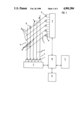
FIG. 1 is a schematic illustration of a system for carrying out the method of measurement,
FIG. 2 is a detail of the area II in FIG. 1,
FIG. 3 illustrates an alternative embodiment of the instrument illustrated in FIG. 1,
FIG. 4 illustrates a third embodiment of the instrument illustrated in FIG. 1,
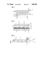
FIG. 5 is a section along the line V--V in FIG. 1,
FIG. 6 is a schematic section through an optical fiber, and
FIG. 7 illustrates a fifth embodiment of the instrument illustrated in FIG. 1.
FIG. 1 on the whole illustrates controls 2 along with the sources 1 of light individually controlled by them. Each source 1 of light, which can for example be an LED, is positioned at the end 3 of an optical fiber 4 associated with one column in a matrix-based measuring instrument 5. Column-associated optical fibers 4 intersect with line-associated optical fibers 6. At one end 7 of each fiber 6 is a light detector 8 that is a component of an optical reader 9. Optical reader 9 is connected to main controls 10 that coordinate controls 2 and optical reader 9 in relation to time and supply an output unit 11 (a video-display terminal and/or printer) with the results. The results can also be stored in a memory 12.
FIG. 2 illustrates the detail II in FIG. 1. It will be evident that the area of contact at the points 13 of intersection between column-associated optical fibers 4 and line-associated optical fibers 6 will become larger or smaller in accordance with the amount of pressure prevailing at that point. Furthermore, the area above the quantity of light introduced by the column-associated optical fibers 4 into the line-associated optical fibers 6 would also expand.
FIG. 3 illustrates another embodiment of a matrix-based instrument 5. Unlike the embodiment illustrated in FIG. 1, a source 1 of light is positioned at both end 3 and end 14 of each column-associated optical fiber 4 and a light detector 8 is positioned at both end 7 and end 15 of each line-as-sociated optical fiber 6. Furthermore, the optical fibers extend in undulations rather than in a straight line between two points 13 of intersection, and the angle between the column-associated and the line-associated optical fibers is roughly right 90° instead of acute as it is in the system illustrated in FIG. 1.
FIG. 4 illustrates a design that is similar to that illustrated in FIG. 3 with the exception that the optical fibers are interwoven.
FIG. 5 is a schematic section through the embodiment illustrated in FIG. 1. Column-associated optical fibers 4 are mounted on a base plate 16 and embedded in a mass of adhesive 17 that secures them such that they come into contact at points 13 of intersection with transverse line-associated optical fibers 6, which are also embedded in another mass of adhesive 19 on an elastic base plate 18.
FIG. 6 illustrates how light travels through optical fibers with a homogeneous index of refraction. Once introduced, the beam of light is completely reflected at the surface 21 of column-associated optical fibers 4. Some of the light, beam 20 for instance, can transfer into a line-associated optical fiber 6 at a point 13 of intersection. This would be impossible, however, for such other components as the beam 21 indicted by the double-headed arrow or the beam 22 indicated by the broken-line arrow.
FIG. 7 illustrates another alternative. The lower end 3 of each column-associated optical fiber 4 is provided with both a source 1 of light and a light detector 8. The upper end of each column-associated optical fiber is bent at an acute angle 23 to create line-associated optical fibers 6, which they intersect at points 13. One individual source 1 is activated at one end 3 of each column-associated optical fiber 4. The other sources are, along with the light detector 8 associated with the same column-associated optical fiber 4 as the source that has just been activated, turned off. The distribution of locally specific pressures throughout an area that is to be tested and that is represented by the broken-line triangle in FIG. 7 can be determined by activating all the other sources of light in sequence.
Claims (18)
1. A method for measuring locally predetermined pressures comprising the steps: forming a matrix of intersecting columns and rows of pressure-transmitting conductors in form of optical fibers; arraying the optical fibers of said columns and the optical fibers of said rows with points of intersection; producing areas of contact at said points of intersection dependent on local pressures at said points of intersection; introducing light at at least one end of only a single optical fiber of a column or a row; reading out the amount of light coupled at points of intersection of all optical fibers with said single optical fiber, said intersecting optical fibers being in contact; and measuring local pressures at points of intersection from variations of the areas of contact between the intersecting optical fibers, measurement of said pressures being dependent on the material of said optical fibers.
2. A method as defined in claim 1, wherein said optical fibers have an index of refraction that is homogeneous over the cross-sections of said optical fibers.
3. A method as defined in claim 1, wherein said intersecting optical fibers are interwoven.
4. A method as defined in claim 1, including the step of embedding said optical fibers in an electrically conductive material.
5. A method as defined in claim 4, wherein said electrically conductive material prevents non-intersecting optical fibers from becoming displaced, said electrically conductive material allowing intersecting optical fibers to come into contact.
6. A method as defined in claim 5, including the step of curving in said optical fibers by at least one undulation between said points of intersection.
7. A method as defined in claim 1, wherein said intersecting optical fibers form an angle between 45° and 90°.
8. A method as defined in claim 1, wherein said step of reading out is carried out at all columns or rows individually or in groups and simultaneously or sequentially.
9. A method as defined in claim 1, wherein light is introduced at both ends of each optical fiber.
10. A method as defined in claim 1, wherein said light is introduced through light-emitting diodes or rapid-action laser diodes.
11. A method as defined in claim 1, wherein said light is read out through light detectors.
12. A method as defined in claim 1, wherein said light is read out at both ends of an optical fiber.
13. A method as defined in claim 12, wherein said light is read out be light detectors comprising p.i.n. diodes.
14. A method as defined in claim 1, including the step of positioning one source of light and one light detector at only one end of each optical fiber, only one source of light emitting light constantly; and measuring light that is coupled-in by all light detectors with the exception of the light detector associated with said source emitting light constantly.
15. A method as defined in claim 14, wherein said one source of light and said one light detector are positioned at one end of optical fibers of said columns; bending said optical fibers of said columns at an acute angle at the other end of said optical fibers of said columns, said other end of said optical fibers of said columns to extend onward and form said rows of optical fibers.
16. A method as defined in claim 1, wherein results of said measuring step are introduced and read out by long sheaves of optical fibers extending to a spatially remote location.
17. A method for measuring locally predetermined pressures comprising the steps: forming a matrix of intersecting columns and rows of pressure-transmitting conductors in form of optical fibers; arraying the optical fibers of said columns and the optical fibers of said rows with points of intersection; producing areas of contact at said points of intersection dependent on local pressures at said points of intersection; introducing light at at least one end of only a single optical fiber of a column or a row; reading out the amount of light coupled at points of intersection of all optical fibers with said single optical fiber, said intersecting optical fibers being in contact; and measuring local pressures at points of intersection from variations of th areas of contact between the intersecting optical fibers, measurement of said pressures being dependent on the material of said optical fibers, said intersecting optical fibers intersecting at a non-perpendicular angle.
18. A method for measuring locally predetermined pressures comprising the steps: forming a matrix of intersecting columns and rows of pressure-transmitting conductors in form of optical fibers; arraying the optical fibers of said columns and the optical fibers of said rows with points of intersection; producing areas of contact at said points of intersection dependent on local pressures at said points of intersection; introducing light at at least one end of only a single optical fiber of a column or a row; reading out the amount of light coupled at points of intersection of all optical fibers with said single optical fiber, said intersecting optical fibers being in contact; and measuring local pressures at points of intersection from variations of the areas of contact between the intersecting optical fibers, measurement of said pressures being dependent on the material of said optical fibers, said optical fibers having an index of refraction that is homogeneous over the cross-sections of said optical fibers, said intersecting optical fibers being interwoven and being embedded in an electrically conductive material for preventing non-intersecting optical fibers from becoming displaced and allowing intersecting optical fibers to come into contact; curving said optical fibers in at least one undulation between the points of intersection, intersecting optical fibers forming an angle therebetween within the range of 45° to 90°; said reading out step occurring at all columns or lines of optical fibers individually or in groups and simultaneously or sequentially; introducing light at both ends of each optical fiber through light-emitting diodes or rapid-action laser diodes; said reading out step being carried out with light detectors at both ends of an optical fiber, said detectors comprising p.i.n. diodes; positioning one source of light and one light detector at only one end of each optical fiber, only one source of light emitting light constantly and having an associated detector, and measuring said coupled-in light with all light detectors except the detector associated with said light source emitting light constantly; bending optical fibers in said columns at an acute angle at one end and extending the bent optical fibers onward to form said rows of optical fibers, the source of light and a light detector being positioned at the other end of the bent optical fibers; introducing and reading out signals representing results of said measurement step with long sheaves of optical fibers to a spatially remote location.
Applications Claiming Priority (2)
| Application Number | Priority Date | Filing Date | Title |
|---|---|---|---|
| DE88102301 | 1988-02-17 | ||
| EP88102301A EP0328703B1 (en) | 1988-02-17 | 1988-02-17 | Measuring method for local measurement of pressures |
Publications (1)
| Publication Number | Publication Date |
|---|---|
| US4901584A true US4901584A (en) | 1990-02-20 |
Family
ID=8198728
Family Applications (1)
| Application Number | Title | Priority Date | Filing Date |
|---|---|---|---|
| US07/311,987 Expired - Fee Related US4901584A (en) | 1988-02-17 | 1989-02-16 | Method of measuring locally specific pressures |
Country Status (4)
| Country | Link |
|---|---|
| US (1) | US4901584A (en) |
| EP (1) | EP0328703B1 (en) |
| AT (1) | ATE68595T1 (en) |
| DE (1) | DE3865665D1 (en) |
Cited By (13)
| Publication number | Priority date | Publication date | Assignee | Title |
|---|---|---|---|---|
| US5378069A (en) * | 1992-08-24 | 1995-01-03 | Product Engineering & Mfg., Inc. | Environmentally safe touch typing keyboard |
| US5446278A (en) * | 1993-12-23 | 1995-08-29 | The United States Of America As Represented By The United States Department Of Energy | Fiber optic sensor employing successively destroyed coupled points or reflectors for detecting shock wave speed and damage location |
| US5551484A (en) * | 1994-08-19 | 1996-09-03 | Charboneau; Kenneth R. | Pipe liner and monitoring system |
| US5577848A (en) * | 1992-08-24 | 1996-11-26 | Bowen; James H. | Light controlled touch pad for cursor and selection control on a computer display |
| DE29716848U1 (en) * | 1997-09-19 | 1998-10-29 | Mutschler Friedolf | Key bit with interchangeable key head |
| US6216546B1 (en) * | 1998-06-13 | 2001-04-17 | Volkswagen Ag | Sensor arrangement for spatially and temporally varying measurements of force or pressure |
| US6267014B1 (en) * | 2000-01-14 | 2001-07-31 | National Research Council Of Canada | Apparatus for sensing a load of pressure applied to a surface |
| US6321605B1 (en) * | 2000-01-14 | 2001-11-27 | National Research Council Of Canada | Surface load and pressure sensing apparatus |
| US20050005706A1 (en) * | 2002-02-11 | 2005-01-13 | Leoni Bordnetz-Systeme Gmbh & Co. Kg | Pressure sensor having an optical waveguide and method for pressure detection |
| US20080025664A1 (en) * | 2006-05-24 | 2008-01-31 | Airbus France | System for measurement and detection of parameters and anomalies |
| US20160103026A1 (en) * | 2013-06-05 | 2016-04-14 | Ev Group E. Thallner Gmbh | Measuring device and method for ascertaining a pressure map |
| US20180299992A1 (en) * | 2013-03-15 | 2018-10-18 | Tactual Labs Co. | Orthogonal frequency scan scheme in touch system |
| EP4220109A1 (en) * | 2022-02-01 | 2023-08-02 | Luxisens Technologies B.V. | Optical fiber pressure sensor array or grid for location, vibration and/or motion sensing and mattress including the same |
Families Citing this family (3)
| Publication number | Priority date | Publication date | Assignee | Title |
|---|---|---|---|---|
| DE4337402A1 (en) * | 1993-10-26 | 1995-04-27 | Mannesmann Ag | Probe for measuring pressure and temperature profiles |
| DE19527957C1 (en) * | 1995-07-29 | 1996-08-22 | Karlsruhe Forschzent | Optoelectronic tactile pressure sensor linked to data processor |
| DE19616952C1 (en) * | 1996-04-27 | 1997-01-23 | Karlsruhe Forschzent | Tactile optoelectronic pressure sensor |
Citations (4)
| Publication number | Priority date | Publication date | Assignee | Title |
|---|---|---|---|---|
| US4360247A (en) * | 1981-01-19 | 1982-11-23 | Gould Inc. | Evanescent fiber optic pressure sensor apparatus |
| US4480183A (en) * | 1982-03-16 | 1984-10-30 | Burroughs Corporation | Multi-plane optical membrane switch apparatus |
| US4733068A (en) * | 1986-04-07 | 1988-03-22 | Rockwell International Corporation | Crossed fiber optic tactile sensor |
| US4781056A (en) * | 1985-03-07 | 1988-11-01 | Sopha Praxis | Optical device for strain detection, method for the measurement of strain by means of the said device and their application to scales |
Family Cites Families (5)
| Publication number | Priority date | Publication date | Assignee | Title |
|---|---|---|---|---|
| DE2529475C3 (en) * | 1975-07-02 | 1981-10-08 | Ewald Max Christian Dipl.-Phys. 6000 Frankfurt Hennig | Electrical circuit arrangement for time-dependent measurement of physical quantities |
| GB2058394B (en) * | 1979-08-30 | 1984-01-04 | Marconi Co Ltd | Pressure sensitive optical fibre cable |
| US4408829A (en) * | 1981-01-30 | 1983-10-11 | Schlumberger Technology Corporation | Fiber optic transducers |
| US4547668A (en) * | 1983-09-14 | 1985-10-15 | Siemens Corporate Research & Support, Inc. | Two-dimensional pressure sensor using retro-reflective tape and semi-transparent medium |
| CA1268640A (en) * | 1985-11-14 | 1990-05-08 | Battelle Development Corporation | Fiber-optical pressure detector |
-
1988
- 1988-02-17 DE DE8888102301T patent/DE3865665D1/en not_active Expired - Lifetime
- 1988-02-17 EP EP88102301A patent/EP0328703B1/en not_active Expired - Lifetime
- 1988-02-17 AT AT88102301T patent/ATE68595T1/en active
-
1989
- 1989-02-16 US US07/311,987 patent/US4901584A/en not_active Expired - Fee Related
Patent Citations (4)
| Publication number | Priority date | Publication date | Assignee | Title |
|---|---|---|---|---|
| US4360247A (en) * | 1981-01-19 | 1982-11-23 | Gould Inc. | Evanescent fiber optic pressure sensor apparatus |
| US4480183A (en) * | 1982-03-16 | 1984-10-30 | Burroughs Corporation | Multi-plane optical membrane switch apparatus |
| US4781056A (en) * | 1985-03-07 | 1988-11-01 | Sopha Praxis | Optical device for strain detection, method for the measurement of strain by means of the said device and their application to scales |
| US4733068A (en) * | 1986-04-07 | 1988-03-22 | Rockwell International Corporation | Crossed fiber optic tactile sensor |
Cited By (17)
| Publication number | Priority date | Publication date | Assignee | Title |
|---|---|---|---|---|
| US5378069A (en) * | 1992-08-24 | 1995-01-03 | Product Engineering & Mfg., Inc. | Environmentally safe touch typing keyboard |
| US5577848A (en) * | 1992-08-24 | 1996-11-26 | Bowen; James H. | Light controlled touch pad for cursor and selection control on a computer display |
| US5446278A (en) * | 1993-12-23 | 1995-08-29 | The United States Of America As Represented By The United States Department Of Energy | Fiber optic sensor employing successively destroyed coupled points or reflectors for detecting shock wave speed and damage location |
| US5551484A (en) * | 1994-08-19 | 1996-09-03 | Charboneau; Kenneth R. | Pipe liner and monitoring system |
| DE29716848U1 (en) * | 1997-09-19 | 1998-10-29 | Mutschler Friedolf | Key bit with interchangeable key head |
| US6216546B1 (en) * | 1998-06-13 | 2001-04-17 | Volkswagen Ag | Sensor arrangement for spatially and temporally varying measurements of force or pressure |
| US6267014B1 (en) * | 2000-01-14 | 2001-07-31 | National Research Council Of Canada | Apparatus for sensing a load of pressure applied to a surface |
| US6321605B1 (en) * | 2000-01-14 | 2001-11-27 | National Research Council Of Canada | Surface load and pressure sensing apparatus |
| US20050005706A1 (en) * | 2002-02-11 | 2005-01-13 | Leoni Bordnetz-Systeme Gmbh & Co. Kg | Pressure sensor having an optical waveguide and method for pressure detection |
| US6912912B2 (en) | 2002-02-11 | 2005-07-05 | Leoni Bordnetz-Systeme Gmbh & Co. Kg | Pressure sensor having an optical waveguide and method for pressure detection |
| US20080025664A1 (en) * | 2006-05-24 | 2008-01-31 | Airbus France | System for measurement and detection of parameters and anomalies |
| US7545998B2 (en) * | 2006-05-24 | 2009-06-09 | Airbus France | System for measurement and detection of parameters and anomalies |
| US20180299992A1 (en) * | 2013-03-15 | 2018-10-18 | Tactual Labs Co. | Orthogonal frequency scan scheme in touch system |
| US20160103026A1 (en) * | 2013-06-05 | 2016-04-14 | Ev Group E. Thallner Gmbh | Measuring device and method for ascertaining a pressure map |
| US10024741B2 (en) * | 2013-06-05 | 2018-07-17 | Ev Group E. Thallner Gmbh | Measuring device and method for ascertaining a pressure map |
| EP4220109A1 (en) * | 2022-02-01 | 2023-08-02 | Luxisens Technologies B.V. | Optical fiber pressure sensor array or grid for location, vibration and/or motion sensing and mattress including the same |
| WO2023148109A1 (en) * | 2022-02-01 | 2023-08-10 | Luxisens Technologies B.V. | Optical fiber pressure sensor array or grid for location, vibration and/or motion sensing and mattress including the same |
Also Published As
| Publication number | Publication date |
|---|---|
| DE3865665D1 (en) | 1991-11-21 |
| EP0328703A1 (en) | 1989-08-23 |
| ATE68595T1 (en) | 1991-11-15 |
| EP0328703B1 (en) | 1991-10-16 |
Similar Documents
| Publication | Publication Date | Title |
|---|---|---|
| US4901584A (en) | Method of measuring locally specific pressures | |
| US3224279A (en) | Accelerometer | |
| US4710760A (en) | Photoelastic touch-sensitive screen | |
| CA1268346A (en) | Optical device for detecting force, method of measuring force by means of the said device and their application to a balance | |
| US4459022A (en) | Fiber optic angular sensor | |
| US5279044A (en) | Measuring device for determining an absolute position of a movable element and scale graduation element suitable for use in such a measuring device | |
| EP0702780B1 (en) | Fiber optic bending and positioning sensor | |
| US4547668A (en) | Two-dimensional pressure sensor using retro-reflective tape and semi-transparent medium | |
| US4555633A (en) | Photoelectric dimension measuring system | |
| US6740862B2 (en) | Optical transducers and methods of making same | |
| US5012679A (en) | Optical sensor | |
| SE449934B (en) | APPARATUS FOR SIMPLE GENERATION AND DETECTION OF REGISTRATIONS | |
| CN104515468B (en) | Optical position measuring device | |
| CN102239384A (en) | Optical apparatus for non-contact measurement or testing of a body surface | |
| CN101089563A (en) | Data exchange system | |
| JP2874813B2 (en) | Electro-optical sensor for linear value measurement | |
| GB2194635A (en) | Photoelectric displacement detector | |
| Yamazaki et al. | Noncontact probe for continuous measurement of surface inclination and position using dynamic irradiation of light beam | |
| CN109708586A (en) | A kind of packaging method of optical fibre Bragg optical grating strain sensor | |
| US5640240A (en) | Probe for surface measurement | |
| JP2004000004U6 (en) | Probe for surface measurement | |
| US6636760B1 (en) | Planar transducer for measuring biomedical pressures | |
| US4405231A (en) | Deformograph | |
| Leal-Junior et al. | Polymer optical fiber sensor system for multi plane bending angle assessment | |
| US6822750B2 (en) | Optical transducers and methods of making same |
Legal Events
| Date | Code | Title | Description |
|---|---|---|---|
| REMI | Maintenance fee reminder mailed | ||
| LAPS | Lapse for failure to pay maintenance fees | ||
| FP | Lapsed due to failure to pay maintenance fee |
Effective date: 19930220 |
|
| STCH | Information on status: patent discontinuation |
Free format text: PATENT EXPIRED DUE TO NONPAYMENT OF MAINTENANCE FEES UNDER 37 CFR 1.362 |