US4901379A - Air excitation hydromassage system - Google Patents
Air excitation hydromassage system Download PDFInfo
- Publication number
- US4901379A US4901379A US07/185,919 US18591988A US4901379A US 4901379 A US4901379 A US 4901379A US 18591988 A US18591988 A US 18591988A US 4901379 A US4901379 A US 4901379A
- Authority
- US
- United States
- Prior art keywords
- air
- nozzle
- cap
- tub
- air flow
- Prior art date
- Legal status (The legal status is an assumption and is not a legal conclusion. Google has not performed a legal analysis and makes no representation as to the accuracy of the status listed.)
- Expired - Fee Related
Links
- 230000005284 excitation Effects 0.000 title abstract description 4
- XLYOFNOQVPJJNP-UHFFFAOYSA-N water Substances O XLYOFNOQVPJJNP-UHFFFAOYSA-N 0.000 claims abstract description 27
- 230000000712 assembly Effects 0.000 claims abstract description 16
- 238000000429 assembly Methods 0.000 claims abstract description 16
- 238000002347 injection Methods 0.000 claims description 22
- 239000007924 injection Substances 0.000 claims description 22
- 238000013019 agitation Methods 0.000 claims description 3
- 238000003491 array Methods 0.000 abstract description 9
- 230000000694 effects Effects 0.000 abstract description 5
- 238000009434 installation Methods 0.000 description 7
- 230000006378 damage Effects 0.000 description 4
- 230000003993 interaction Effects 0.000 description 4
- 239000000203 mixture Substances 0.000 description 4
- 230000004048 modification Effects 0.000 description 4
- 238000012986 modification Methods 0.000 description 4
- 208000027418 Wounds and injury Diseases 0.000 description 3
- 208000014674 injury Diseases 0.000 description 3
- 229920000915 polyvinyl chloride Polymers 0.000 description 3
- 239000004800 polyvinyl chloride Substances 0.000 description 3
- 206010014357 Electric shock Diseases 0.000 description 2
- 208000002193 Pain Diseases 0.000 description 2
- 238000007792 addition Methods 0.000 description 2
- 239000000463 material Substances 0.000 description 2
- 230000036316 preload Effects 0.000 description 2
- 230000009471 action Effects 0.000 description 1
- 230000003213 activating effect Effects 0.000 description 1
- 230000004913 activation Effects 0.000 description 1
- 239000012190 activator Substances 0.000 description 1
- 230000009286 beneficial effect Effects 0.000 description 1
- 230000006835 compression Effects 0.000 description 1
- 238000007906 compression Methods 0.000 description 1
- 238000005553 drilling Methods 0.000 description 1
- 230000014759 maintenance of location Effects 0.000 description 1
- 238000004519 manufacturing process Methods 0.000 description 1
- 230000013011 mating Effects 0.000 description 1
- 238000000034 method Methods 0.000 description 1
- 238000000465 moulding Methods 0.000 description 1
- 210000003205 muscle Anatomy 0.000 description 1
- 230000036407 pain Effects 0.000 description 1
- 230000008569 process Effects 0.000 description 1
- 238000007789 sealing Methods 0.000 description 1
Images
Classifications
-
- A—HUMAN NECESSITIES
- A61—MEDICAL OR VETERINARY SCIENCE; HYGIENE
- A61H—PHYSICAL THERAPY APPARATUS, e.g. DEVICES FOR LOCATING OR STIMULATING REFLEX POINTS IN THE BODY; ARTIFICIAL RESPIRATION; MASSAGE; BATHING DEVICES FOR SPECIAL THERAPEUTIC OR HYGIENIC PURPOSES OR SPECIFIC PARTS OF THE BODY
- A61H33/00—Bathing devices for special therapeutic or hygienic purposes
- A61H33/02—Bathing devices for use with gas-containing liquid, or liquid in which gas is led or generated, e.g. carbon dioxide baths
- A61H33/026—Gas nozzles specially adapted therefor
-
- A—HUMAN NECESSITIES
- A61—MEDICAL OR VETERINARY SCIENCE; HYGIENE
- A61H—PHYSICAL THERAPY APPARATUS, e.g. DEVICES FOR LOCATING OR STIMULATING REFLEX POINTS IN THE BODY; ARTIFICIAL RESPIRATION; MASSAGE; BATHING DEVICES FOR SPECIAL THERAPEUTIC OR HYGIENIC PURPOSES OR SPECIFIC PARTS OF THE BODY
- A61H33/00—Bathing devices for special therapeutic or hygienic purposes
- A61H33/60—Components specifically designed for the therapeutic baths of groups A61H33/00
- A61H33/601—Inlet to the bath
- A61H33/6021—Nozzles
- A61H33/6063—Specifically adapted for fitting in bathtub walls
Definitions
- the present invention relates generally to hydromassage bath systems and more particularly, to such systems wherein air is expelled from a plurality of jets mounted on the wall of a bathtub for activating the water into a massaging action on the user therein.
- hydromassage as a means for relieving fatigued muscles and soothing the aches and pains of physical injuries is certainly well-known in the prior art.
- Most hydromassage systems known in the United States are of the type which employ a plurality of venturi jets which mix air and water utilizing a high speed flow of water to suction air into the mixture.
- An altogether different type of hydromassage system has become popular, primarily in Europe and this European system relies entirely on the injection of air such as into a bath full of water.
- One of the advantages of a system which uses only air is that it tends to be simpler and less costly to manufacture and therefore more readily available to the general public at lower cost while still providing beneficial hydromassage effects.
- Typical air injection systems force air through a plurality of exit ports mounted within a tub to activate the water and massage the user. Because of the differences in the behavior of air bubbles injected into a bathtub full of water as compared to a mixture of air and water and particularly, high pressure water, it is preferable in air injection systems to use a large plurality of injection ports preferably at the bottom of the tub as opposed to the side walls of the tub. Unfortunately, the process of connecting an air hose to each of a plurality of inlet ports at the bottom of a tub can become quite complex and expensive thereby defeating the otherwise advantageous simplicity of using only air instead of a combination of air and water.
- one prior art air injection system uses an air manifold in which a separate parallel pipe connection is provided to each of a large plurality of air injector ports.
- Another prior art system requires placing an inner tub surface inside the existing tub surface in order to facilitate installation of a plurality of jets between the floor of the original tub and the floor of the newly inserted tub.
- Still another prior art system requires the use of exotic bathtub structures which substantially preclude modification of an existing bathtub structure and thus significantly increases the cost of the overall system.
- Still an additional prior art system utilizes a special air bubble-generating mat that must be manually placed inside the bathtub each time the system is to be used, thereby reducing the comfort and convenience of the hydromassage concept.
- the aforementioned need is solved by means of the present invention which provides a unique air injection hydromassage system utilizing one or more serial interconnections of adjustable air nozzles each of which may be varied to control the level of air flow into the tub as well as the direction of air into the tub through that nozzle.
- installation of the present invention requires drilling holes through the floor of the tub
- the low profile components of the present invention, as well as the simple interconnection scheme thereof simplifies installation and reduces the number of separate components.
- Such distinct advantages reduce the overall cost of modifying an existing tub to incorporate the air injection system of the present invention.
- the present invention obviates the need for complex air manifold control systems, extensive air flow piping and the need for specially constructed tub structures which must be used in some prior art systems to accommodate air injection installations.
- the present invention once installed, is a permanent system which does not require a user to manually place a mat or any other extraneous structure into the bottom of the tub before using same.
- Each of the novel nozzles of the present invention is a three-part structure comprising a nozzle cap, a nozzle body and a nozzle foot. Only the nozzle cap and the uppermost castellated portion of the nozzle body extend above the tub floor, but are configured to be extremely low profile to minimize any risk of discomfort or injury to the user. By simply rotating the nozzle cap of the present invention, one can readily control the air flow direction and force on a nozzle-by-nozzle basis thereby modifying the water agitation to accommodate each user's preferences.
- the nozzle foot is a uniquely configured low profile, high compression strength structure which permits installation in most cases without permanently altering the position of the tub. Furthermore, the nozzle foot configuration permits interconnection in a serial arrangement using flexible hose connected to a remotely positioned air blower activated by a pneumatic control which may be mounted in a side wall of the bathtub thereby obviating any possibility of electric shock.
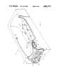
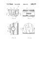
- FIG. 1 is an isometric schematic illustration of an entire system using the present invention
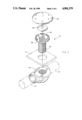
- FIG. 2 is an exploded view of an individual nozzle assembly of the present invention
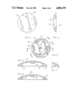
- FIG. 3 is a top view of the nozzle cap of the present invention.
- FIG. 4 is a side view of the nozzle cap of the present invention.
- FIG. 5 is a bottom view of the nozzle cap of the present invention.
- FIG. 6 is a cross-sectional view of the nozzle cap of the present invention taken along lines 6--6 of FIG. 5;
- FIG. 7 is a partial cross-section view of a portion of the nozzle cap of the invention taken along lines 7--7 of FIG. 5;
- FIG. 8 is a cross-sectional view of the nozzle cap of the invention taken along lines 8--8 of FIG. 5;
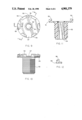
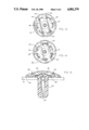
- FIG. 9 is a top view of the nozzle body of the present invention.
- FIG. 10 is a side view of the nozzle body of the present invention.
- FIG. 11 is a cross-sectional view of the nozzle body of the present invention taken along lines 11--11 of FIG. 9;
- FIG. 12 is a partial cross-sectional view of a portion of the nozzle body of the present invention taken along lines 12--12 of FIG. 9;
- FIGS. 13 and 14 illustrate the interaction between the nozzle cap and nozzle body of the present invention and different air flow characteristics thereof
- FIG. 15 is a cross-sectional view of the nozzle cap and nozzle body of the present invention.
- FIG. 16 is a side view of the nozzle foot of the invention.
- FIG. 17 is a side view partially broken away of the nozzle foot of the present invention.
- FIG. 18 is a top view of the nozzle foot of the present invention.
- FIG. 19 is a cross-sectional view of the nozzle foot taken along lines 19--19 of FIG. 16.
- the air excitation bath system 10 of the present invention comprises a bathtub 12 having a tub floor 14 into which is mounted the air control system 15 of the present invention.
- the air control system 15 comprises a plurality of nozzle assemblies 16 interconnected by a plurality of flexible hoses 18.
- the air control system 15 comprises a plurality of nozzle assemblies 16 interconnected by a plurality of flexible hoses 18.
- the two serial arrays are interconnected at a common tee 20 which is in turn connected by a larger flexible hose 22 to a blower 30 by means of a first safety loop 24 and a second safety loop 28, the latter including a check valve 26.
- Blower 30 is provided with a blower control 32 to which is connected a control button 34 by means of a pneumatic line 35.
- a blower control 32 to which is connected a control button 34 by means of a pneumatic line 35.
- FIG. 1 whereby the entire air control system comprises a total of eight nozzle assemblies 16, the actual number of serial arrays and the actual number of nozzle assemblies may be varied depending upon the particular configuration desired for a given bathtub and the preferences of a given user. Accordingly, the precise number and location of nozzle assemblies is not to be deemed limiting of the present invention.
- each nozzle assembly 16 comprises a nozzle cap 36, a nozzle body 38 and a nozzle foot 40.
- an umbrella-shaped check valve 60 is positioned between the nozzle cap 36 and the nozzle body 38, in a manner to be disclosed more fully hereinafter, for the purpose of preventing water from inside the tub from entering the air control system of the present invention.
- the nozzle body 38 is designed to extend through a hole drilled into the tub floor 14 and into a nozzle foot 40 which is positioned below the tub so that the tub floor 14 is effectively sandwiched between the nozzle body and the nozzle foot.
- each nozzle assembly 16 When each nozzle assembly 16 is installed in a tub floor, the only parts thereof which extend above the tub floor and are thus available inside the tub wall, are the nozzle cap 36 and that portion of the nozzle body 38 which appears castellated. In fact, it is the interaction between the nozzle cap 36 and a castellated portion 49 of nozzle body 38 which controls the air flow through each nozzle assembly in a manner to be described hereinafter. On the other hand, the nozzle foot 40 and the threaded portion 52 of nozzle body 38 reside below the tub floor 14 when the nozzle body 16 is installed.
- Each such nozzle foot 40 which is actually a tee, is preferably made of polyvinylchloride and interconnects half inch diameter flexible hose members 18 to the nozzle bodies on the underside of the tub floor 14.
- the offset configuration of the nozzle foot facilitates maximum air flow for downstream fittings while maintaining a long nozzle body grip range and low under tub profile.
- the unique design facilitates ease of molding with sufficient strength to support the tub in transport and to withstand a reasonable amount of abuse in transport and use.
- the polyvinylchloride material facilitates ease of installation.
- each nozzle cap 36 is provided with a plurality of apertures 37 through which the air may flow in an upward direction out of each nozzle assembly 16.
- Each nozzle cap 36 is also provided with a plurality of slots 39 through which air may flow in a lateral direction substantially tangential to the tub floor surface.
- the nozzle cap 36 is provided with a very slim profile whereby to minimize any chance of possible discomfort or injury to the user.
- the bottom side of nozzle cap 36 that is the side facing the tub floor and generally hidden from the user, may be understood best by reference to FIGS. 5-8.
- nozzle cap 36 comprises a plurality of symmetrically located cleats 42 and a plurality of symmetrically located snaps 44.
- An alignment mark 43 is also provided.
- the cleats 42 provide loading points against the nozzle body in the event that a side load is made to bear on the cap such as when somebody stands in the tub and applies his weight to a cap.
- the snaps 44 serve the multifold purpose of holding the nozzle cap 36 onto the nozzle body 38. They also preload the cap onto the body and provide a friction retention of adjustment position.
- the sides of the snaps 44 provide stop edges located adjacent ridges in the nozzle body thereby providing limits to cap adjustment rotation. As seen best in FIG.
- the snaps 44 on the underside of the cap 36 are in symmetrically alternating position with respect to the cleats 42. These rigid features of the cap ride over the nozzle body head periphery in a slip fit arrangement as will be discussed hereinafter more fully below.
- the particular shapes of the cleats 42 and the snaps 44 are designed to enable proper mating with the underlying nozzle body 38 in a manner to be disclosed hereinafter.
- the inside central portion of the cap 36 is provided with a boss 46 which is designed to locate and retain the umbrella check valve 60 in the center of the nozzle assembly and to provide a preload onto this check valve for sealing it at low tub water levels.
- the nozzle body 38 of the present invention is provided with a castellated upper portion 49 and a threaded lower portion 52.
- the castellated upper portion 49 is provided with a plurality of symmetrically spaced air blocks 50, one of which is configured in the form of a stop lock 58 having a stop ridge 59 seen best in cross-section in FIG. 12.
- the threaded portion 52 of nozzle body 38 is provided with an air channel 54 the upper portion of which terminates in the plane of the castellated upper portion 49 in the form of a hex-shaped opening 56.
- the hex configuration of opening 56 is designed to provide easy wrench tightening of the threaded body 52 into the underlying nozzle foot 40.
- FIGS. 13-15 demonstrate that adjustment is accomplished in the present invention by rotating the nozzle cap 36 on the nozzle body 38. Air flow can be modified to permit air to exit the top holes 37 of the cap 36 and/or to exit the side of the cap 36 through slots 39. The adjustment may also produce a shut off configuration or substantially full shut off so that the user can stop or substantially reduce the air flow out of some nozzle assemblies while increasing the air flow out of others.
- FIG. 13 represents the configuration of nozzle cap 36 and nozzle body 38 when the nozzle assembly is in its shut off configuration. More specifically, referring to FIG. 13 it will be seen that the relative rotational positions of the cap 36 and the body 38 are such that the air blocks 50 are positioned over the holes 37 and simultaneously are positioned to block the side air slots 39. Simultaneously, each of the air flow paths 57 of the body 38 is interrupted either by a cleat 42 or a snap 44. Accordingly, in the relative rotational positions of the nozzle cap and body of FIG. 13 there is little or no air flow through that particular nozzle assembly. On the other hand, the relative position of the cap and body of FIG.
- FIG. 14 positions the air blocks 50 so that they cover only a portion of the apertures 37 and further so that they do not block the slots 39. In this particular configuration, while the predominant air flow is through slots 39, a limited air flow may also exit the apertures 37. It will be understood that slightly additional counterclockwise rotation of cap 36 relative to body 38 from the position shown in FIG. 14, would permit full air flow through apertures 37 and substantially full air flow through slots 39. Thus it can be seen by virtue of FIGS. 13 and 14 that there is a range of full adjustment from substantially no air flow to full air flow provided by the novel design of the present invention.
- FIG. 15 provides a side cross-sectional view of the interconnected body and cap relative to the tub floor 14.
- the cap 36 and castellated body portion 49 are interconnected in relative rotational engagement so that the user may rotate the cap 36 in the manner illustrated in FIGS. 13 and 14 to achieve the variation in air flow to obtain the desired adjustment thereof for each nozzle assembly.
- the umbrella-shaped check valve 60 is positioned between the cap 36 and the body 38 to prevent water from flowing back through the air channel 54 while still allowing air to exit the air channel 54 in the manner illustrated in phantom in FIG. 15.
- a deflector 62 deflects the air through channel 54 in such a manner that it raises the annular periphery of the check valve 60 to permit the air to exit through the cap 36.
- the center of the check valve 60 rests against the boss 46 provided at the inside center of the cap 36. While the cap 36 is rotational in its configuration on the body 38, it is nevertheless not easily removed therefrom by virtue of the annular recess 51 on the stops 50 of the castellated portion 49 of the body 38, which are adapted to receive a ridge 45 on the snaps 44 of cap 36 as seen best in FIG. 6. Limitation of adjustability, which is a preferable characteristic, is provided by the interaction of a ridge 59 on stop block 58 of the body 38 and an annular recess 47 on each of the cleats 42 as seen best in FIG. 7.
- each nozzle foot 40 is characterized by a pair of interconnect ports 64 which form opposite ends of an integral pipe or cylinder and which provide means for interconnecting the nozzle assembly 16 in a serial configuration by means of flex hoses 18 as seen best in FIG. 1.
- Each such port is provided with a number of hose stops 65 which prevent damage to the interior of the nozzle foot 40.
- Each nozzle foot is provided with a nozzle body threaded receptacle 66 which may be seen best in FIG. 16.
- This threaded receptacle is designed to mate with the threaded portion 52 of a nozzle body and is basically a hollow cylinder open at the bottom end to permit free flow of air from the interconnecting hose 18 through the port 64 and the receptacle 66 and up through the nozzle body 38.
- Each nozzle foot 40 is preferably made of a polyvinylchloride material and is preferably provided with a plurality of ribs such as ribs 68, 69 and 70 to increase the compressive strength thereof.
- the top of the nozzle foot 40 is provided with a flat, circular, tub-engagement surface 72 which is designed to engage the bottom outside surface of the tub floor 14 when fully threaded onto the threaded portion 52 of nozzle body 38. In this manner, the nozzle assembly 16 is securely attached to the tub floor surface 14 by compressively engaging the tub surface between the surface 72 of nozzle foot 40 and the lower portion of castellated portion 49 of nozzle body 38.
- the nozzle foot 40 is provided with a plurality of depth lines 74 to facilitate installation by indicating cutting limits. As shown in FIG. 1, when the nozzle foot 40 is the last in a series array of nozzle assemblies 16, its port 64 pointing away from the source of air is preferably provided with a cap 17 so that all of the air flow or substantially all of the air flow is forced up into the bathtub through the water therein.
- the system utilizes an air control serial array of adjustable nozzle assemblies preferably installed on the bottom of the tub to provide the user with means for adjusting the rate and direction of the air flow through the water to massage different parts of the body.
- the air control system is characterized by at least one and preferably two or more serial arrays of adjustable nozzle assemblies. Each such array is serially interconnected by a plurality of flexible hoses. The respective arrays are interconnected, preferably to a common flexible hose which is in turn connected to an air blower through at least one safety loop and a check valve.
- the air blower may be controlled by a control apparatus designed to respond to a pneumatic activator connected at the wall of the tub so that the user can turn the system on or off without risk of electric shock.
- Each nozzle assembly of the present invention is provided with a cap, a body and a foot as well as an additional check valve located between the cap and the body.
- the cap and the body are specially configured to permit adjustability of air flow from either substantially off to substantially full flow and also provide means for directing air flow laterally along the surface of the floor of the tub and/or vertically toward the top surface of the water.
- An especially novel feature of the present invention is the design of a nozzle foot which is positioned beneath the tub floor and is provided with a unique low profile configuration to substantially minimize the space required beneath the tub surface in order to interconnect the nozzle assemblies to one another and to the blower.
- the present invention provides a unique air injection hydromassage system which is easy to install and which uses a few, simple, low cost components while at the same time providing certain advantageous adjustability features more conventionally found in whirlpool bath-type hydromassage systems of the prior art which are inherently more complicated and more costly than the air injection system of the present invention.
Abstract
Description
Claims (8)
Priority Applications (3)
| Application Number | Priority Date | Filing Date | Title |
|---|---|---|---|
| US07/185,919 US4901379A (en) | 1988-04-25 | 1988-04-25 | Air excitation hydromassage system |
| EP19890905850 EP0374222A4 (en) | 1988-04-25 | 1989-04-21 | Air excitation hydromassage system |
| PCT/US1989/001732 WO1989010112A1 (en) | 1988-04-25 | 1989-04-21 | Air excitation hydromassage system |
Applications Claiming Priority (1)
| Application Number | Priority Date | Filing Date | Title |
|---|---|---|---|
| US07/185,919 US4901379A (en) | 1988-04-25 | 1988-04-25 | Air excitation hydromassage system |
Publications (1)
| Publication Number | Publication Date |
|---|---|
| US4901379A true US4901379A (en) | 1990-02-20 |
Family
ID=22682959
Family Applications (1)
| Application Number | Title | Priority Date | Filing Date |
|---|---|---|---|
| US07/185,919 Expired - Fee Related US4901379A (en) | 1988-04-25 | 1988-04-25 | Air excitation hydromassage system |
Country Status (3)
| Country | Link |
|---|---|
| US (1) | US4901379A (en) |
| EP (1) | EP0374222A4 (en) |
| WO (1) | WO1989010112A1 (en) |
Cited By (34)
| Publication number | Priority date | Publication date | Assignee | Title |
|---|---|---|---|---|
| US5381563A (en) * | 1992-12-24 | 1995-01-17 | Roger Carrier | Check valve, and hydromassaging apparatus comprising at least one of such a check valve |
| US5474102A (en) * | 1991-07-15 | 1995-12-12 | Lopez; Robert | Fluid distribution manifold |
| US5745934A (en) * | 1996-06-10 | 1998-05-05 | Softub, Inc. | Spa apparatus with hanging structural liner |
| US5794280A (en) * | 1997-01-08 | 1998-08-18 | Softub, Inc. | Spa apparatus with heat transferring hanging interior structural liner |
| US5799345A (en) * | 1996-06-10 | 1998-09-01 | Softub, Inc. | Spa apparatus with multiple sections |
| US6081945A (en) * | 1998-11-13 | 2000-07-04 | Keene; Linda | Rotary hydrotherapy nozzle |
| US6317903B1 (en) * | 2000-04-06 | 2001-11-20 | Bains Ultra Inc. | Bathtub design with therapeutical treatment devices |
| WO2002043543A2 (en) * | 2000-11-30 | 2002-06-06 | C.G. Air Systemes Inc. | Hidden air jet and air massage system |
| US6477724B1 (en) * | 2002-03-04 | 2002-11-12 | Gestion Ultra International Inc. | Water evacuation conduit for hydro massaging tub |
| US20030000010A1 (en) * | 2001-06-29 | 2003-01-02 | Hideo Shimizu | Blow-off nozzle type bathtub with illumination |
| US6581217B2 (en) * | 2001-07-25 | 2003-06-24 | Sam M. Marcos | Directional air vents for spas and jetted bathtubs |
| US6629320B1 (en) * | 2002-01-29 | 2003-10-07 | Saratoga Spa & Bath Co., Inc. | Fluid flow systems and methods |
| US20030233704A1 (en) * | 2000-04-17 | 2003-12-25 | Miguel Castellote | Air massage system for bathtub |
| US20050150041A1 (en) * | 2004-01-12 | 2005-07-14 | Jacuzzi, Inc. | Apparatus for directing air toward a bather |
| US20050172393A1 (en) * | 1999-04-16 | 2005-08-11 | Miguel Castellote | Air massage system for bathtub |
| US20050211612A1 (en) * | 2004-03-25 | 2005-09-29 | Mattson Roy W Jr | Water suction purification device |
| US20050277854A1 (en) * | 2004-06-14 | 2005-12-15 | Leroy Hatchett | Heated fluid, feet massage apparatus |
| AT413499B (en) * | 2003-09-19 | 2006-03-15 | Koller Rudolf | AIR NOZZLE FOR WATER BASIN, BATHTUBS OD. DGL. |
| US20060090256A1 (en) * | 2004-11-01 | 2006-05-04 | Acryline Usa, Inc. | Drain system for tub |
| US20060230517A1 (en) * | 2005-04-14 | 2006-10-19 | Bedard Paul R | Air injector system apparatus and methods for a tub or spa |
| US20070033726A1 (en) * | 2003-04-11 | 2007-02-15 | Nicolas Lebrun | Method for mounting a recessed micro jet in a whirlpool bath and a kit therefor |
| US20080172783A1 (en) * | 2007-01-19 | 2008-07-24 | Smith Scott A | Bathtub with air-water injection system |
| US20100266776A1 (en) * | 2009-04-21 | 2010-10-21 | Mt Industries, Inc. | Automated skin spray and dry system |
| US20100294849A1 (en) * | 2009-05-20 | 2010-11-25 | Groner David M | Air Control And Aromatherapy Module |
| US20110133004A1 (en) * | 2009-12-04 | 2011-06-09 | Mt Industries, Inc. | Skin treatment spray nozzle system for automatic spray gantry |
| US20110133001A1 (en) * | 2009-12-04 | 2011-06-09 | Mt Industries, Inc. | Hand held skin treatment spray system |
| US20140101843A1 (en) * | 2007-08-09 | 2014-04-17 | Ecotech Marine, Llc | Foot spa tub pump and method |
| US8790319B2 (en) | 2011-07-15 | 2014-07-29 | Sunless, Inc. | Method and system for applying a heated skin treatment spray |
| US9066634B2 (en) | 2012-08-01 | 2015-06-30 | Balboa Water Group, Inc. | Air jet fittings for bathing installations |
| US9066635B2 (en) | 2012-08-01 | 2015-06-30 | Balboa Water Group, Inc. | Air jet fittings with recess features for bathing installations |
| US9278367B2 (en) | 2012-09-17 | 2016-03-08 | Sunless, Inc. | Precision pumping system for spray treatment cycles |
| US9295612B2 (en) | 2007-08-09 | 2016-03-29 | Ecotech Marine, Llc | Foot spa tub pump and method |
| US9775772B2 (en) | 2015-03-03 | 2017-10-03 | Kohler Co. | Whirlpool bathtub and purging system |
| US20180178105A1 (en) * | 2016-12-27 | 2018-06-28 | Bestway Inflatables & Material Corp. | Swimming training apparatus |
Families Citing this family (3)
| Publication number | Priority date | Publication date | Assignee | Title |
|---|---|---|---|---|
| NL8900221A (en) * | 1989-01-30 | 1990-08-16 | Berend Leewerik | WHIRLPOOLS WORKING WITH AIR INFLATION SYSTEMS. |
| EP0437048A3 (en) * | 1989-12-12 | 1991-07-24 | Carrier, Roger | Improved hydromassaging apparatus, and check valve assembly for such apparatus |
| DE4005688A1 (en) * | 1990-02-23 | 1991-08-29 | Schuessler Guenter | HYDROMASSAGE NOZZLE WITH DECOMPRESSION ROOM AND DRAINAGE SEQUENCE |
Citations (19)
| Publication number | Priority date | Publication date | Assignee | Title |
|---|---|---|---|---|
| US2313994A (en) * | 1941-07-24 | 1943-03-16 | Akron Brass Mfg Company Inc | Spray nozzle |
| GB1224308A (en) * | 1968-11-27 | 1971-03-10 | Jacuzzi Research Inc | Hydro-therapy tank assembly |
| GB1460206A (en) * | 1974-02-19 | 1976-12-31 | Jacuzzi Research Inc | Hydromassage apparatus |
| GB1496613A (en) * | 1974-12-24 | 1977-12-30 | Kulisch R | Air bubble massage apparatus |
| GB2026317A (en) * | 1978-07-26 | 1980-02-06 | Dupont R | Massage installation |
| US4207877A (en) * | 1978-04-17 | 1980-06-17 | Marquardt Arthur F | Bathtub aerator |
| US4264039A (en) * | 1977-12-20 | 1981-04-28 | South Pacific Industries | Aerator |
| GB1604587A (en) * | 1978-05-31 | 1981-12-09 | May M A | Swimming pool accessory |
| US4340039A (en) * | 1980-06-19 | 1982-07-20 | Sta-Rite Industries, Inc. | Hydromassage apparatus |
| GB2107180A (en) * | 1981-10-07 | 1983-04-27 | Baths Limited Spa | Therapeutic baths |
| GB2112670A (en) * | 1982-01-04 | 1983-07-27 | Philip Edward Chalberg | Jet nozzle assembly |
| US4398669A (en) * | 1977-05-09 | 1983-08-16 | Teledyne Industries, Inc. | Fluid-spray discharge apparatus |
| GB2114021A (en) * | 1982-01-19 | 1983-08-17 | Clive Richard Randle | Baths |
| GB2120546A (en) * | 1982-04-28 | 1983-12-07 | Alan Fitzgeorge Carr | Improvements in or relating to water aerating apparatus |
| US4419775A (en) * | 1981-08-10 | 1983-12-13 | Ebert Thomas P | Whirlpool bath |
| GB2159404A (en) * | 1984-07-21 | 1985-12-04 | John Theophilus Brueton | Hydrotherapy apparatus |
| GB2161072A (en) * | 1984-11-02 | 1986-01-08 | John Theophilus Brueton | Hydrotherapy apparatus |
| GB2169799A (en) * | 1985-01-17 | 1986-07-23 | Heatons Bathrooms | Activated water baths |
| US4672692A (en) * | 1984-09-07 | 1987-06-16 | Savage Nigel C | Bath with air jet |
Family Cites Families (3)
| Publication number | Priority date | Publication date | Assignee | Title |
|---|---|---|---|---|
| DE238866C (en) * | 1910-09-24 | 1911-10-05 | Adjustable device for introducing gases into bathtubs and. like | |
| AR224785A1 (en) * | 1980-05-19 | 1982-01-15 | Dupont Robert | CHECK VALVE WITH DIRECTIONAL INJECTOR |
| DE3607788A1 (en) * | 1985-04-26 | 1986-12-04 | Günter 6074 Rödermark Schüssler | WATER BASIN WITH AIR SPRAYER |
-
1988
- 1988-04-25 US US07/185,919 patent/US4901379A/en not_active Expired - Fee Related
-
1989
- 1989-04-21 WO PCT/US1989/001732 patent/WO1989010112A1/en not_active Application Discontinuation
- 1989-04-21 EP EP19890905850 patent/EP0374222A4/en not_active Withdrawn
Patent Citations (19)
| Publication number | Priority date | Publication date | Assignee | Title |
|---|---|---|---|---|
| US2313994A (en) * | 1941-07-24 | 1943-03-16 | Akron Brass Mfg Company Inc | Spray nozzle |
| GB1224308A (en) * | 1968-11-27 | 1971-03-10 | Jacuzzi Research Inc | Hydro-therapy tank assembly |
| GB1460206A (en) * | 1974-02-19 | 1976-12-31 | Jacuzzi Research Inc | Hydromassage apparatus |
| GB1496613A (en) * | 1974-12-24 | 1977-12-30 | Kulisch R | Air bubble massage apparatus |
| US4398669A (en) * | 1977-05-09 | 1983-08-16 | Teledyne Industries, Inc. | Fluid-spray discharge apparatus |
| US4264039A (en) * | 1977-12-20 | 1981-04-28 | South Pacific Industries | Aerator |
| US4207877A (en) * | 1978-04-17 | 1980-06-17 | Marquardt Arthur F | Bathtub aerator |
| GB1604587A (en) * | 1978-05-31 | 1981-12-09 | May M A | Swimming pool accessory |
| GB2026317A (en) * | 1978-07-26 | 1980-02-06 | Dupont R | Massage installation |
| US4340039A (en) * | 1980-06-19 | 1982-07-20 | Sta-Rite Industries, Inc. | Hydromassage apparatus |
| US4419775A (en) * | 1981-08-10 | 1983-12-13 | Ebert Thomas P | Whirlpool bath |
| GB2107180A (en) * | 1981-10-07 | 1983-04-27 | Baths Limited Spa | Therapeutic baths |
| GB2112670A (en) * | 1982-01-04 | 1983-07-27 | Philip Edward Chalberg | Jet nozzle assembly |
| GB2114021A (en) * | 1982-01-19 | 1983-08-17 | Clive Richard Randle | Baths |
| GB2120546A (en) * | 1982-04-28 | 1983-12-07 | Alan Fitzgeorge Carr | Improvements in or relating to water aerating apparatus |
| GB2159404A (en) * | 1984-07-21 | 1985-12-04 | John Theophilus Brueton | Hydrotherapy apparatus |
| US4672692A (en) * | 1984-09-07 | 1987-06-16 | Savage Nigel C | Bath with air jet |
| GB2161072A (en) * | 1984-11-02 | 1986-01-08 | John Theophilus Brueton | Hydrotherapy apparatus |
| GB2169799A (en) * | 1985-01-17 | 1986-07-23 | Heatons Bathrooms | Activated water baths |
Cited By (56)
| Publication number | Priority date | Publication date | Assignee | Title |
|---|---|---|---|---|
| US5474102A (en) * | 1991-07-15 | 1995-12-12 | Lopez; Robert | Fluid distribution manifold |
| US5381563A (en) * | 1992-12-24 | 1995-01-17 | Roger Carrier | Check valve, and hydromassaging apparatus comprising at least one of such a check valve |
| US5745934A (en) * | 1996-06-10 | 1998-05-05 | Softub, Inc. | Spa apparatus with hanging structural liner |
| US5749107A (en) * | 1996-06-10 | 1998-05-12 | Softub, Inc. | Spa apparatus with hanging structural liner |
| US5799345A (en) * | 1996-06-10 | 1998-09-01 | Softub, Inc. | Spa apparatus with multiple sections |
| US5794280A (en) * | 1997-01-08 | 1998-08-18 | Softub, Inc. | Spa apparatus with heat transferring hanging interior structural liner |
| US6081945A (en) * | 1998-11-13 | 2000-07-04 | Keene; Linda | Rotary hydrotherapy nozzle |
| US20050172393A1 (en) * | 1999-04-16 | 2005-08-11 | Miguel Castellote | Air massage system for bathtub |
| US7503082B2 (en) | 1999-04-16 | 2009-03-17 | C. G. Air Systèmes Inc. | Air massage system for bathtub |
| US6317903B1 (en) * | 2000-04-06 | 2001-11-20 | Bains Ultra Inc. | Bathtub design with therapeutical treatment devices |
| US20030233704A1 (en) * | 2000-04-17 | 2003-12-25 | Miguel Castellote | Air massage system for bathtub |
| US20040083544A1 (en) * | 2000-11-30 | 2004-05-06 | C.G. Air Systemes Inc. | Hidden air jet with unidirectional flow mechanism and air massage system including at least one of these jets |
| US6427257B1 (en) * | 2000-11-30 | 2002-08-06 | C. G. Air Systemes, Inc | Hidden air jet with unidirectional flow mechanism and air massage system including at least one of these jets |
| WO2002043543A3 (en) * | 2000-11-30 | 2002-12-27 | Cg Air Systemes Inc | Hidden air jet and air massage system |
| WO2002043543A2 (en) * | 2000-11-30 | 2002-06-06 | C.G. Air Systemes Inc. | Hidden air jet and air massage system |
| US7665158B2 (en) | 2000-11-30 | 2010-02-23 | C.G. Air Systemes Inc. | Hidden air jet with unidirectional flow mechanism and air massage system including at least one of these jets |
| EP1275365A2 (en) * | 2001-06-29 | 2003-01-15 | Hideo Shimizu | Blow-off nozzle type bathtub with illumination |
| EP1275365A3 (en) * | 2001-06-29 | 2004-02-04 | Hideo Shimizu | Blow-off nozzle type bathtub with illumination |
| US6877171B2 (en) * | 2001-06-29 | 2005-04-12 | Hideo Shimizu | Blow-off nozzle type bathtub with illumination |
| US20030000010A1 (en) * | 2001-06-29 | 2003-01-02 | Hideo Shimizu | Blow-off nozzle type bathtub with illumination |
| US6581217B2 (en) * | 2001-07-25 | 2003-06-24 | Sam M. Marcos | Directional air vents for spas and jetted bathtubs |
| US6629320B1 (en) * | 2002-01-29 | 2003-10-07 | Saratoga Spa & Bath Co., Inc. | Fluid flow systems and methods |
| US6477724B1 (en) * | 2002-03-04 | 2002-11-12 | Gestion Ultra International Inc. | Water evacuation conduit for hydro massaging tub |
| US20070033726A1 (en) * | 2003-04-11 | 2007-02-15 | Nicolas Lebrun | Method for mounting a recessed micro jet in a whirlpool bath and a kit therefor |
| AT413499B (en) * | 2003-09-19 | 2006-03-15 | Koller Rudolf | AIR NOZZLE FOR WATER BASIN, BATHTUBS OD. DGL. |
| US7162753B2 (en) | 2004-01-12 | 2007-01-16 | Jacuzzi, Inc. | Apparatus for directing air toward a bather |
| EP1557149A2 (en) | 2004-01-12 | 2005-07-27 | Jacuzzi, Inc. | Apparatus for directing air toward a bather |
| US20050150041A1 (en) * | 2004-01-12 | 2005-07-14 | Jacuzzi, Inc. | Apparatus for directing air toward a bather |
| US20050211612A1 (en) * | 2004-03-25 | 2005-09-29 | Mattson Roy W Jr | Water suction purification device |
| US20050277854A1 (en) * | 2004-06-14 | 2005-12-15 | Leroy Hatchett | Heated fluid, feet massage apparatus |
| US7454802B2 (en) | 2004-11-01 | 2008-11-25 | Acryline Usa, Inc. | Drain system for tub |
| US20060090256A1 (en) * | 2004-11-01 | 2006-05-04 | Acryline Usa, Inc. | Drain system for tub |
| US7849529B2 (en) * | 2005-04-14 | 2010-12-14 | Bedard Paul R | Air injector system apparatus and methods for a tub or spa |
| US20060230517A1 (en) * | 2005-04-14 | 2006-10-19 | Bedard Paul R | Air injector system apparatus and methods for a tub or spa |
| US20080172783A1 (en) * | 2007-01-19 | 2008-07-24 | Smith Scott A | Bathtub with air-water injection system |
| US20140101843A1 (en) * | 2007-08-09 | 2014-04-17 | Ecotech Marine, Llc | Foot spa tub pump and method |
| US9283141B2 (en) * | 2007-08-09 | 2016-03-15 | Ecotech Marine, Llc | Foot spa tub pump and method |
| US11684544B2 (en) | 2007-08-09 | 2023-06-27 | Ecotech, Llc | Foot spa tub pump and method |
| US11219576B2 (en) | 2007-08-09 | 2022-01-11 | Ecotech, Llc | Foot spa tub pump and method |
| US10716732B2 (en) | 2007-08-09 | 2020-07-21 | Ecotech Marine, Llc | Foot spa tub pump and method |
| US10285903B2 (en) | 2007-08-09 | 2019-05-14 | Ecotech Marine, Llc | Foot spa tub pump and method |
| US9737460B2 (en) | 2007-08-09 | 2017-08-22 | Ecotech Marine, Llc | Foot spa tub pump and method |
| US9295612B2 (en) | 2007-08-09 | 2016-03-29 | Ecotech Marine, Llc | Foot spa tub pump and method |
| US20100266776A1 (en) * | 2009-04-21 | 2010-10-21 | Mt Industries, Inc. | Automated skin spray and dry system |
| US8671472B2 (en) | 2009-05-20 | 2014-03-18 | David M. Groner | Air control and aromatherapy module |
| US20100294849A1 (en) * | 2009-05-20 | 2010-11-25 | Groner David M | Air Control And Aromatherapy Module |
| US8784390B2 (en) * | 2009-12-04 | 2014-07-22 | Sunless, Inc. | Skin treatment spray nozzle system for automatic spray gantry |
| US20110133001A1 (en) * | 2009-12-04 | 2011-06-09 | Mt Industries, Inc. | Hand held skin treatment spray system |
| US20110133004A1 (en) * | 2009-12-04 | 2011-06-09 | Mt Industries, Inc. | Skin treatment spray nozzle system for automatic spray gantry |
| US8790319B2 (en) | 2011-07-15 | 2014-07-29 | Sunless, Inc. | Method and system for applying a heated skin treatment spray |
| US9066635B2 (en) | 2012-08-01 | 2015-06-30 | Balboa Water Group, Inc. | Air jet fittings with recess features for bathing installations |
| US9066634B2 (en) | 2012-08-01 | 2015-06-30 | Balboa Water Group, Inc. | Air jet fittings for bathing installations |
| US9278367B2 (en) | 2012-09-17 | 2016-03-08 | Sunless, Inc. | Precision pumping system for spray treatment cycles |
| US9775772B2 (en) | 2015-03-03 | 2017-10-03 | Kohler Co. | Whirlpool bathtub and purging system |
| US10071018B2 (en) | 2015-03-03 | 2018-09-11 | Kohler Co. | Whirlpool bathtub and purging system |
| US20180178105A1 (en) * | 2016-12-27 | 2018-06-28 | Bestway Inflatables & Material Corp. | Swimming training apparatus |
Also Published As
| Publication number | Publication date |
|---|---|
| EP0374222A1 (en) | 1990-06-27 |
| WO1989010112A1 (en) | 1989-11-02 |
| EP0374222A4 (en) | 1991-01-16 |
Similar Documents
| Publication | Publication Date | Title |
|---|---|---|
| US4901379A (en) | Air excitation hydromassage system | |
| US5418984A (en) | Hydrotherapy seat structure for a hydrotherapy spa, tub or swimming pool | |
| US4126905A (en) | Floating therapy pool | |
| US5333322A (en) | Add-on seat module for swimming pool | |
| US4340982A (en) | Hydrotherapy bath or spa | |
| US4122846A (en) | Bubbling device for the treatment of the human body | |
| US3559634A (en) | Therapeutic bathtub | |
| JPH06507816A (en) | Modular cushion construction with foam base | |
| US5404598A (en) | Bathtub add on hydrotherapy apparatus | |
| US4238859A (en) | Spill-over spa | |
| EP1713429B1 (en) | Air bath | |
| US6752773B2 (en) | Bubbling bath mat | |
| US6209148B1 (en) | Floating water massage device | |
| US4101988A (en) | Baths | |
| US5617591A (en) | Head rest assembly | |
| CA2006113A1 (en) | Air excitation hydromassage system | |
| US4908888A (en) | Dry hydro-massage unit | |
| US20040148694A1 (en) | Flow control device for tub, spa, or shower | |
| US7614095B2 (en) | Air bath with bypass vent | |
| US20090106889A1 (en) | Therapeutic bath liner | |
| CA1317417C (en) | Dry hydro-massage unit | |
| RU196879U1 (en) | Bathing device | |
| US20020002736A1 (en) | Combination hydrothermal bath and bidet | |
| GB2069330A (en) | Aerated baths | |
| WO2003088890A1 (en) | Bubbling bath mat with segmented valve control |
Legal Events
| Date | Code | Title | Description |
|---|---|---|---|
| AS | Assignment |
Owner name: HYDRABATHS, INC., 2100 SOUTH FAIRVIEW STREET, SANT Free format text: ASSIGNMENT OF ASSIGNORS INTEREST.;ASSIGNORS:CHALBERG, PHILIP E.;MC KNIGHT, JAMES P.;REEL/FRAME:004888/0279 Effective date: 19880419 Owner name: HYDRABATHS, INC., CALIFORNIA Free format text: ASSIGNMENT OF ASSIGNORS INTEREST;ASSIGNORS:CHALBERG, PHILIP E.;MC KNIGHT, JAMES P.;REEL/FRAME:004888/0279 Effective date: 19880419 |
|
| REMI | Maintenance fee reminder mailed | ||
| FEPP | Fee payment procedure |
Free format text: PAYOR NUMBER ASSIGNED (ORIGINAL EVENT CODE: ASPN); ENTITY STATUS OF PATENT OWNER: SMALL ENTITY |
|
| FPAY | Fee payment |
Year of fee payment: 4 |
|
| SULP | Surcharge for late payment | ||
| REMI | Maintenance fee reminder mailed | ||
| LAPS | Lapse for failure to pay maintenance fees | ||
| AS | Assignment |
Owner name: BAY VIEW FINANCIAL CORPORATION AND BAY VIEW BANK, Free format text: SECURITY AGREEMENT;ASSIGNOR:HYDRABATH, INC.;REEL/FRAME:009227/0911 Effective date: 19980414 |
|
| AS | Assignment |
Owner name: HYDRABATH, INC., CALIFORNIA Free format text: RELEASE BY SECURED PARTY;ASSIGNOR:COAST BUSINESS CREDIT;REEL/FRAME:009257/0972 Effective date: 19980416 |
|
| STCH | Information on status: patent discontinuation |
Free format text: PATENT EXPIRED DUE TO NONPAYMENT OF MAINTENANCE FEES UNDER 37 CFR 1.362 |