US4901356A - Voice transmission system - Google Patents
Voice transmission system Download PDFInfo
- Publication number
- US4901356A US4901356A US07/134,934 US13493487A US4901356A US 4901356 A US4901356 A US 4901356A US 13493487 A US13493487 A US 13493487A US 4901356 A US4901356 A US 4901356A
- Authority
- US
- United States
- Prior art keywords
- assembly
- microphone
- amplifier
- housing
- microphone assembly
- Prior art date
- Legal status (The legal status is an assumption and is not a legal conclusion. Google has not performed a legal analysis and makes no representation as to the accuracy of the status listed.)
- Expired - Lifetime
Links
Images
Classifications
-
- H—ELECTRICITY
- H04—ELECTRIC COMMUNICATION TECHNIQUE
- H04R—LOUDSPEAKERS, MICROPHONES, GRAMOPHONE PICK-UPS OR LIKE ACOUSTIC ELECTROMECHANICAL TRANSDUCERS; DEAF-AID SETS; PUBLIC ADDRESS SYSTEMS
- H04R1/00—Details of transducers, loudspeakers or microphones
- H04R1/08—Mouthpieces; Microphones; Attachments therefor
- H04R1/083—Special constructions of mouthpieces
-
- A—HUMAN NECESSITIES
- A62—LIFE-SAVING; FIRE-FIGHTING
- A62B—DEVICES, APPARATUS OR METHODS FOR LIFE-SAVING
- A62B18/00—Breathing masks or helmets, e.g. affording protection against chemical agents or for use at high altitudes or incorporating a pump or compressor for reducing the inhalation effort
- A62B18/08—Component parts for gas-masks or gas-helmets, e.g. windows, straps, speech transmitters, signal-devices
Definitions
- the present invention relates to voice transmission or communication systems for gas masks in general and to a microphone assembly threadedly connected to the emitter passage and an amplifier assembly threadedly connected to the microphone assembly in particular.
- Berman U.S. Pat. No. 3,314,424 includes a microphone inside the mask and an amplifier assembly outside the mask, with an electrical cable extending therebetween and passing through a sealed grommet in the mask.
- Erdman, et al. U.S. Pat. No. 3,243,511 assigned to the same company as the Berman patent, showing substantially the same mask as the Berman patent with the amplifier circuit being disclosed.
- Lewis U.S. Pat. No. 3,180,333 discloses a gas mask communication system including a generally U-shaped holder connected to the mask.
- the holder includes the amplification speaker in one end portion thereof and the batteries for operating the speaker system in the other end portion thereof.
- the batteries and amplification system are connected in circuit with a microphone inside the mask adjacent the user's mouth. Additional or parallel speakers can be plugged into the Lewis mask communication system including, for example, a speaker attached to the belt of the wearer.
- the principal object of the present invention is to have a microphone assembly and amplifier assembly that are readily connected to the existing emitter passage and to one another.
- the emitter passage has a female threaded section adjacent its end normally to house a voice emitter diaphragm held in place by a perforated cover.
- the voice emitter diaphragm and cover can be readily removed, the microphone assembly can be screwed into the female section of the emitter passage and the amplifier assembly can be screwed into the microphone assembly.
- Another object of the present invention is to provide a compact and lightweight voice transmission system that follows the head of the mask user.
- the microphone assembly and amplifier assembly of the present invention employ relatively small, plastic bodies reducing the weight and enhancing the compactness of the system.
- the lightweight and compact voice transmission and amplification system of the present invention follows the head of the user to project the person's voice in the direction his face is pointing.
- Yet another object of the present invention is to provide a positive resilient electrical contact between the amplifier assembly and the microphone assembly during installation.
- the microphone assembly is provided with two spaced circular contacts on the end thereof. These circular contacts are engaged by spring loaded pins or ball contacts carried by the amplifier assembly.
- the spring loaded pins or ball contacts are normally urged to a position guaranteeing positive engagement with the contacts when the amplifier assembly is fully threaded onto the microphone assembly.
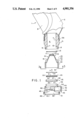
- FIG. 1 is an exploded view of the components of the voice transmission system of the present invention prior to assembly or installation on the gas mask;
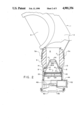
- FIG. 2 is a vertical elevation partially in section showing the microphone assembly and amplifier assembly of the present invention installed on the emitter passage of a gas mask used to protect the face of a person, such as a fire fighter.
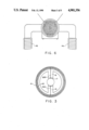
- FIG. 3 is an enlarged end view of the plastic body of the microphone assembly as taken on the plane 3--3 of FIG. 1 showing the concentric circular contacts carried by the outer end of that body;
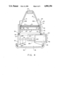
- FIG. 4 is an enlarged section of the microphone assembly and amplifier assembly as installed with the electrical circuit and end contacts being schematically illustrated;
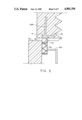
- FIG. 5 is an enlarged view of the spring load contactor ball carried by the amplifier assembly just prior to making engagement with the contact on the end of the microphone assembly body;
- FIG. 6 is a front view of part of the mask and the voice transmission system of the present invention.
- a gas mask indicated generally at 1, includes a face piece 2 held tightlyagainst the head of the user by straps encircling the back of the head.
- a transparent viewing plate 3 is mounted in and sealingly secured to the face piece 2.
- a person wearing the mask 1 on inhaling receives filtered air drawn through a conventional inhalation tube 4A and on exhaling exhausts air through a conventional exhalation tube 4B.
- the inhalation andexhalation tubes have check valves and filters mounted therein to preclude noxious gases or contaminants entrained in the air from entering the inside of face plate 2 and transparent face plate 3.
- a conventional plastic voice emitter body 5 is secured to the mask 1 by a clamp 5A received in an external groove on body 5.
- the emitter body 5 has a stepped emitter passage 6 extending therethrough and being formed by bore 7 and counterbore 8.
- the counterbore8 has female threads 9 thereon which normally mate with threads on the perforated cover retaining a voice emitter diaphragm in the emitter passage.
- a chamfered relief 11 and shoulder 12 are formed between the bore7 and counterbore 8.
- a circular flat rubber seal 13 is mounted in an annular groove 14 provided in shoulder 12.
- a microphone assembly indicated generally at 15 is partially received in and threadedly mounted to the emitter passage.
- the microphone assembly includes a lightweight plastic body 16 having an inner end face 17, two diametrically opposed, angled spokes 18, a first radially projecting annular shoulder 19, a first axially extending annular wall 20, a second radially projecting annular shoulder 21 and a second enlarged diameter axially extending wall 22.
- the inner end wall 17 has a microphone cartridge 24 mounted therein.
- This microphone cartridge is sold by Cord Electronics, Inc. under part number U62B.
- the radially outer surface of the first axial wall 20 of microphone assembly body 16 has male threads 25 thereon.
- the microphone assembly body16 is screwed into the emitter passage 6 with threads 25 mating with threads 9 on counterbore 8.
- Body 16 is threadedly advanced into the emitter passage until the inner end of first annular shoulder 19 bottoms out on and compresses circular flat rubber seal 13.
- the microphone assembly body is then properly positioned in and sealed to the emitter body 5 to preclude outside air from entering mask 1.
- the radially inner surface of the second axial wall 22 of the microphone assembly body 16 hasfemale threads 26.
- Electrical leads 28A and 28B are connected at their inner respective ends to opposite sides of microphone cartridge 24 and extend through and are embedded in the microphone assembly body 16 to the forward end wall thereof as will be described in more detail below.
- a voice emitter diaphragm 29 is mounted in the microphone assembly 15 in a position inside second axially extending wall 22 against or immediately adjacent the inner side of second shoulder 21.
- a circular flat rubber seal30 is mounted on the internal side of shoulder 21, with the voice emitter diaphragm engaging the circular flat rubber seal to provide air tight sealing contact therebetween.
- the voice emitter diaphragm includes parallel plates 31 and 32 having a layer of mylar 33 sandwiched therebetween. The voice emitter diaphragm blocks noxious or contaminated air from entering the microphone assembly while being capable of transmitting some sound therethrough.
- the voice emitter diaphragm 29 is held in position by a dish lock ring indicated generally at 35, having a base wall 36 and an annular side wall 37.
- the radially outer surface of sidewall 37 is threaded as indicated at 38.
- the dish shaped lock ring 35 is threaded down the female threads 26 onsecond axial wall 22 of the microphone assembly body. Lock ring 35 bears against plate 32 of the voice emitter diaphragm 29 to hold the same against circular flat rubber seal 30.
- the end face 39 of microphone assembly body 16 has two spaced circular electrical contacts 40 and 41. These concentric circular contacts 40 and 41 are respectively connected to leads 28A and 28B in body 16 as best shown in FIG. 3. Spaced circular contacts 40 and 41 are adapted to providean electrical connection with the amplifier assembly, indicated generally at 42.
- the amplifier assembly 42 includes a lightweight, preferably integrally molded, plastic body 43 having a battery compartment 44, an open forward end 46 and an inner sleeve 47.
- An amplifier board 48 and speaker 49 are mounted in main compartment 45 of body 43.
- the amplifier 48 may be purchased from SGS Semiconductor under part number TDA1904, and the speaker 49 may be purchased from Cord Electronics, Inc. under part number 70 RPOSN-4.
- a perforated speaker cover 50 is threaded onto body 44 as indicated at 51 to cover the outer end of the speaker 49 and the open end 46 of body 44.
- the battery compartment 44 has a selectively removable cover 52. When the cover is off, a 9 V battery 53 may be positioned in the battery compartment 44 to provide a source of power for the voice transmission system of the present invention.
- Leads 28C and 28D extend from the batteryterminals to the amplifier board 48.
- Lead 28E extends from the amplifier board to a metallic contactor ball 54 positioned on a base wall 55 of amplifier assembly body 43.
- the contactor ball 54 is spring biased as indicated at 56 normally resiliently to urge the ball 54 forwardly. Instead of the ball illustrated, it will be appreciated that a metallic pin could be used as the contactor.
- a second spring loaded contactor ball 57 is mounted on base wall 55 in a position generally diametrically opposite ball 54. Spring loaded balls 54 and 57 are adapted respectively positively to engage circular contacts 41 and 40 on the microphone assembly when the amplifier assembly is screwed onto the microphone assembly.
- the radially outer surface of sleeve 47 has male threads 59 thereon.
- Male threads 59 mate with female threads 26 internally positionedon the second axially extending wall 22 of the microphone assembly body 16.
- the amplifier assembly is threadedly advanced into the microphone assembly until the inner end of sleeve 47 bottoms out against base wall 36 of lock ring 35. In such position, the base wall 55 of body 43 also abuts the end face 39 of microphone assembly body 16. Since the balls 54 and 57 normallyextend forwardly of base wall 55, the balls 54 and 57 will be depressed against their respective contacts to insure a positive electrical contact.
- Spring loaded ball 57 has electrical lead 28F extending through body 43 to a connection with amplifier board 48. Electrical leads 28G and 28H extend from the amplifier board to the speaker 49. Leads 28A through 28H thus provide a closed electrical circuit between the battery 53, the amplifier board 48, the microphone cartridge 24, and the speaker 49 when the amplifier assembly is fully threaded onto the microphone assembly providing an electrical connection therebetween.
- the electrical circuit schematically disclosed herein includes additional capacitors and resistors (not shown). This circuit is basically conventional and does notform part of this invention except for the means of making electrical contact between the amplifier assembly and microphone assembly.
- the microphone cartridge 24 is positioned inside the voice communication system under the mouth of the user while the speaker 48 is positioned within the voice communication system but pointedoutwardly in a direction away from the mask.
- the microphone assembly and amplifier assembly can be readily operably connected by completing two threaded connections. If the amplifier assembly malfunctions for any reason, the masked user can quickly disassemble the amplifier assembly by unthreading the same from the microphone assembly. By doing this, the user's voice can then be transmitted through the diaphragm assembly 29.
Abstract
Description
Claims (8)
Priority Applications (3)
| Application Number | Priority Date | Filing Date | Title |
|---|---|---|---|
| US07/134,934 US4901356A (en) | 1987-12-18 | 1987-12-18 | Voice transmission system |
| US07/758,707 US5138666A (en) | 1987-12-18 | 1991-09-09 | Voice transmission system |
| US08/792,804 US5371804A (en) | 1987-12-18 | 1991-11-15 | Voice transmission system |
Applications Claiming Priority (1)
| Application Number | Priority Date | Filing Date | Title |
|---|---|---|---|
| US07/134,934 US4901356A (en) | 1987-12-18 | 1987-12-18 | Voice transmission system |
Related Child Applications (1)
| Application Number | Title | Priority Date | Filing Date |
|---|---|---|---|
| US18693288A Continuation-In-Part | 1987-12-18 | 1988-04-27 |
Publications (1)
| Publication Number | Publication Date |
|---|---|
| US4901356A true US4901356A (en) | 1990-02-13 |
Family
ID=22465679
Family Applications (1)
| Application Number | Title | Priority Date | Filing Date |
|---|---|---|---|
| US07/134,934 Expired - Lifetime US4901356A (en) | 1987-12-18 | 1987-12-18 | Voice transmission system |
Country Status (1)
| Country | Link |
|---|---|
| US (1) | US4901356A (en) |
Cited By (24)
| Publication number | Priority date | Publication date | Assignee | Title |
|---|---|---|---|---|
| WO1991007859A1 (en) * | 1989-11-08 | 1991-05-30 | Actron Manufacturing Company | Voice transmission system |
| WO1992015369A1 (en) * | 1991-03-04 | 1992-09-17 | Bloomfield John W | Retrofitting gas mask voice amplifier unit |
| US5159641A (en) * | 1991-07-31 | 1992-10-27 | Figgie International, Inc. | Microphone circuit control mechanism for breathing apparatus |
| US5224474A (en) * | 1991-03-04 | 1993-07-06 | Bloomfield John W | Retrofitting gas mask voice amplifier unit with easily actuated switch means |
| WO1995009676A1 (en) * | 1993-10-01 | 1995-04-13 | Minnesota Mining And Manufacturing Company | Speech transmission adaptor for use with a respirator mask |
| WO1995013689A1 (en) * | 1993-11-10 | 1995-05-18 | Actron Manufacturing Company | Voice transmission adaptor assembly |
| EP0705622A1 (en) * | 1994-09-30 | 1996-04-10 | Puritan-Bennett Corporation | Quick-donning full face oxygen mask with inflatable harness and soft foldable lens |
| US20030025396A1 (en) * | 2001-08-06 | 2003-02-06 | Cheng-Lai Shen | Power supply system |
| US20030224838A1 (en) * | 2001-07-18 | 2003-12-04 | Greg Skillicorn | Mask communication system |
| US20050063561A1 (en) * | 2003-09-22 | 2005-03-24 | Joseph Birli | Dual microphone assembly for mask |
| US20050201548A1 (en) * | 2004-03-12 | 2005-09-15 | Joseph Birli | Telephone interface for mask |
| US20050213782A1 (en) * | 2004-03-26 | 2005-09-29 | Mark Miller | Voice amplifier for mask |
| US6997178B1 (en) * | 1998-11-25 | 2006-02-14 | Thomson-Csf Sextant | Oxygen inhaler mask with sound pickup device |
| US20060050917A1 (en) * | 2004-09-03 | 2006-03-09 | Greg Skillicorn | Lapel microphone with push to talk switch |
| US20060177084A1 (en) * | 2004-07-29 | 2006-08-10 | Greg Skillicorn | Mask amplifier with separated elements |
| US20060180153A1 (en) * | 2005-01-27 | 2006-08-17 | Bernie Schaub | Assembly for mounting a device to a mask |
| US20080035145A1 (en) * | 2006-02-10 | 2008-02-14 | Adams Jonathan D | Communication system for heads-up display |
| US20090052714A1 (en) * | 2007-08-21 | 2009-02-26 | Ultra Electronics Audiopack, Inc. | High noise immunity emergency resonder communication system |
| US20130263848A1 (en) * | 2012-04-10 | 2013-10-10 | Drager Safety Ag & Co. Kgaa | Gas mask |
| US9560459B2 (en) | 2014-05-16 | 2017-01-31 | D. Wheatley Enterprises, Inc. | Modular voice amplification system for protective mask |
| US9833644B2 (en) | 2014-09-03 | 2017-12-05 | Undersea Sensor Systems, Inc. | Air purification respirator voice amplifier |
| US11222648B1 (en) * | 2019-05-11 | 2022-01-11 | ReddyPort Inc. | Positive pressure ventilation microphone system, nebulizer, and related methods |
| US20220399004A1 (en) * | 2021-06-11 | 2022-12-15 | Suetsugu Katsunori | Voice augmentation device, partition, mask, mouth shield, and face shield |
| US20230080573A1 (en) * | 2016-06-22 | 2023-03-16 | Lucca Ventures, Inc. | Patient respiratory mask with integrated microphone and method of patient communication utilizing the same |
Citations (19)
| Publication number | Priority date | Publication date | Assignee | Title |
|---|---|---|---|---|
| US1139177A (en) * | 1914-05-07 | 1915-05-11 | John M Ganzer | Fireman's helmet. |
| US1242672A (en) * | 1916-05-20 | 1917-10-09 | Western Electric Co | Telephone equipment. |
| US1344349A (en) * | 1919-05-17 | 1920-06-22 | Mickelson George Arthur | Open-face gas-mask |
| US1656914A (en) * | 1925-10-17 | 1928-01-24 | Hart Henry Ridgeway | Communicating helmet |
| GB549518A (en) * | 1941-05-02 | 1942-11-25 | Standard Telephones Cables Ltd | Improvements in or relating to microphones |
| US2942072A (en) * | 1957-06-17 | 1960-06-21 | Gen Dynamics Corp | Helmet communication system |
| US2950360A (en) * | 1956-11-27 | 1960-08-23 | Baldwin Piano Co | Microphone support structure |
| US2953129A (en) * | 1958-04-21 | 1960-09-20 | Sierra Engineering Company | Valve and microphone base assembly |
| US3180333A (en) * | 1963-05-29 | 1965-04-27 | Acme Prot Equipment Co | Gas mask communication system |
| US3243511A (en) * | 1962-10-01 | 1966-03-29 | Douglas Aircraft Co Inc | Amplifier circuit |
| US3314424A (en) * | 1962-11-14 | 1967-04-18 | Douglas Aircraft Co Inc | Microphone support device for a mask |
| US4072831A (en) * | 1976-09-10 | 1978-02-07 | Instrument Systems Corporation | Voice transmitting apparatus for a breathing mask |
| US4237341A (en) * | 1978-09-25 | 1980-12-02 | Richards Paul E | Portable self-contained amplifier and loudspeaker apparatus |
| US4374301A (en) * | 1980-09-18 | 1983-02-15 | Gentex Corporation | Local external communication device for enclosed helmet and mask assembly |
| US4400591A (en) * | 1981-07-17 | 1983-08-23 | Jennings Daniel E | Simulated space helmet |
| US4471174A (en) * | 1979-11-16 | 1984-09-11 | Nava Pier Luigi | Support for helmets in general provided with microtelephone |
| US4508936A (en) * | 1980-07-16 | 1985-04-02 | Gentex Corporation | Local external communication system |
| GB2165721A (en) * | 1984-10-16 | 1986-04-16 | Charles William Dickinson | A speech facility for a facemask |
| US4683588A (en) * | 1985-10-17 | 1987-07-28 | Mel Goldberg | Face mask with voice modifying capability |
-
1987
- 1987-12-18 US US07/134,934 patent/US4901356A/en not_active Expired - Lifetime
Patent Citations (19)
| Publication number | Priority date | Publication date | Assignee | Title |
|---|---|---|---|---|
| US1139177A (en) * | 1914-05-07 | 1915-05-11 | John M Ganzer | Fireman's helmet. |
| US1242672A (en) * | 1916-05-20 | 1917-10-09 | Western Electric Co | Telephone equipment. |
| US1344349A (en) * | 1919-05-17 | 1920-06-22 | Mickelson George Arthur | Open-face gas-mask |
| US1656914A (en) * | 1925-10-17 | 1928-01-24 | Hart Henry Ridgeway | Communicating helmet |
| GB549518A (en) * | 1941-05-02 | 1942-11-25 | Standard Telephones Cables Ltd | Improvements in or relating to microphones |
| US2950360A (en) * | 1956-11-27 | 1960-08-23 | Baldwin Piano Co | Microphone support structure |
| US2942072A (en) * | 1957-06-17 | 1960-06-21 | Gen Dynamics Corp | Helmet communication system |
| US2953129A (en) * | 1958-04-21 | 1960-09-20 | Sierra Engineering Company | Valve and microphone base assembly |
| US3243511A (en) * | 1962-10-01 | 1966-03-29 | Douglas Aircraft Co Inc | Amplifier circuit |
| US3314424A (en) * | 1962-11-14 | 1967-04-18 | Douglas Aircraft Co Inc | Microphone support device for a mask |
| US3180333A (en) * | 1963-05-29 | 1965-04-27 | Acme Prot Equipment Co | Gas mask communication system |
| US4072831A (en) * | 1976-09-10 | 1978-02-07 | Instrument Systems Corporation | Voice transmitting apparatus for a breathing mask |
| US4237341A (en) * | 1978-09-25 | 1980-12-02 | Richards Paul E | Portable self-contained amplifier and loudspeaker apparatus |
| US4471174A (en) * | 1979-11-16 | 1984-09-11 | Nava Pier Luigi | Support for helmets in general provided with microtelephone |
| US4508936A (en) * | 1980-07-16 | 1985-04-02 | Gentex Corporation | Local external communication system |
| US4374301A (en) * | 1980-09-18 | 1983-02-15 | Gentex Corporation | Local external communication device for enclosed helmet and mask assembly |
| US4400591A (en) * | 1981-07-17 | 1983-08-23 | Jennings Daniel E | Simulated space helmet |
| GB2165721A (en) * | 1984-10-16 | 1986-04-16 | Charles William Dickinson | A speech facility for a facemask |
| US4683588A (en) * | 1985-10-17 | 1987-07-28 | Mel Goldberg | Face mask with voice modifying capability |
Cited By (45)
| Publication number | Priority date | Publication date | Assignee | Title |
|---|---|---|---|---|
| WO1991007859A1 (en) * | 1989-11-08 | 1991-05-30 | Actron Manufacturing Company | Voice transmission system |
| WO1992015369A1 (en) * | 1991-03-04 | 1992-09-17 | Bloomfield John W | Retrofitting gas mask voice amplifier unit |
| US5224474A (en) * | 1991-03-04 | 1993-07-06 | Bloomfield John W | Retrofitting gas mask voice amplifier unit with easily actuated switch means |
| US5224473A (en) * | 1991-03-04 | 1993-07-06 | Bloomfield John W | Retrofitting gas mask voice amplifier unit with easily actuated switch means |
| US5159641A (en) * | 1991-07-31 | 1992-10-27 | Figgie International, Inc. | Microphone circuit control mechanism for breathing apparatus |
| US7234462B2 (en) | 1993-10-01 | 2007-06-26 | 3M Innovative Properties Company | Speech transmission adaptor for use with a respirator mask |
| WO1995009676A1 (en) * | 1993-10-01 | 1995-04-13 | Minnesota Mining And Manufacturing Company | Speech transmission adaptor for use with a respirator mask |
| KR100326132B1 (en) * | 1993-10-01 | 2002-07-31 | 미네소타 마이닝 앤드 매뉴팩춰링 캄파니 | Speech transfer adapters used in respirator masks and respirator masks |
| US6382206B1 (en) | 1993-10-01 | 2002-05-07 | 3M Innovative Properties Company | Speech transmission adaptor for use with a respirator mask |
| US5463693A (en) * | 1993-11-10 | 1995-10-31 | Audiopack Sound Systems Inc. | Voice amplification adapter assembly for face mask |
| WO1995013689A1 (en) * | 1993-11-10 | 1995-05-18 | Actron Manufacturing Company | Voice transmission adaptor assembly |
| US5957132A (en) * | 1994-09-30 | 1999-09-28 | Puritan-Bennett Corporation | Quick-donning full face oxygen mask with inflatable harness and soft foldable lens |
| US6070580A (en) * | 1994-09-30 | 2000-06-06 | Be Intellectual Property, Inc. | Quick-donning full face oxygen mask with inflatable harness and soft foldable lens |
| EP0705622A1 (en) * | 1994-09-30 | 1996-04-10 | Puritan-Bennett Corporation | Quick-donning full face oxygen mask with inflatable harness and soft foldable lens |
| US6443155B1 (en) | 1994-09-30 | 2002-09-03 | Be Intellectual Property, Inc. | Quick-donning full face oxygen mask with inflatable harness and soft foldable lens |
| US20070193585A1 (en) * | 1994-09-30 | 2007-08-23 | Mcdonald Thomas K | Quick-donning full face oxygen mask with inflatable harness and soft foldable lens |
| US6672307B2 (en) | 1994-09-30 | 2004-01-06 | Be Intellectual Property, Inc. | Quick-donining full face oxygen mask with inflatable harness and soft foldable lens |
| US20040060562A1 (en) * | 1994-09-30 | 2004-04-01 | Mcdonald Thomas K. | Quick-donning full face oxygen mask with inflatable harness and soft foldable lens |
| US7178526B2 (en) | 1994-09-30 | 2007-02-20 | Be Intellectual Property, Inc. | Quick-donning full face oxygen mask with inflatable harness and soft foldable lens |
| US20110168182A1 (en) * | 1994-09-30 | 2011-07-14 | Be Intellectual Property, Inc. | Quick-donning full face oxygen mask with inflatable harness and soft foldable lens |
| US6997178B1 (en) * | 1998-11-25 | 2006-02-14 | Thomson-Csf Sextant | Oxygen inhaler mask with sound pickup device |
| US20030224838A1 (en) * | 2001-07-18 | 2003-12-04 | Greg Skillicorn | Mask communication system |
| US20030025396A1 (en) * | 2001-08-06 | 2003-02-06 | Cheng-Lai Shen | Power supply system |
| US20050063561A1 (en) * | 2003-09-22 | 2005-03-24 | Joseph Birli | Dual microphone assembly for mask |
| US20080025546A1 (en) * | 2003-09-22 | 2008-01-31 | Joseph Birli | Dual microphone assembly for mask |
| US7457427B2 (en) | 2003-09-22 | 2008-11-25 | Ultra Electronics Audiopack, Inc. | Dual microphone assembly for mask |
| US20050201548A1 (en) * | 2004-03-12 | 2005-09-15 | Joseph Birli | Telephone interface for mask |
| US7394905B2 (en) | 2004-03-26 | 2008-07-01 | Ultra Electronics Audiopack, Inc. | Voice amplifier for mask |
| US20050213782A1 (en) * | 2004-03-26 | 2005-09-29 | Mark Miller | Voice amplifier for mask |
| US20060177084A1 (en) * | 2004-07-29 | 2006-08-10 | Greg Skillicorn | Mask amplifier with separated elements |
| US20060050917A1 (en) * | 2004-09-03 | 2006-03-09 | Greg Skillicorn | Lapel microphone with push to talk switch |
| US7349551B2 (en) | 2004-09-03 | 2008-03-25 | Ultra Electronics Audiopack, Inc. | Lapel microphone with push to talk switch |
| US20060180153A1 (en) * | 2005-01-27 | 2006-08-17 | Bernie Schaub | Assembly for mounting a device to a mask |
| US20080035145A1 (en) * | 2006-02-10 | 2008-02-14 | Adams Jonathan D | Communication system for heads-up display |
| US20100308991A1 (en) * | 2006-02-10 | 2010-12-09 | Undersea Sensor Systems. Inc. | Communication system for heads-up display |
| US20090052714A1 (en) * | 2007-08-21 | 2009-02-26 | Ultra Electronics Audiopack, Inc. | High noise immunity emergency resonder communication system |
| CN103357125A (en) * | 2012-04-10 | 2013-10-23 | 德拉格安全股份两合公司 | Gas mask |
| US20130263848A1 (en) * | 2012-04-10 | 2013-10-10 | Drager Safety Ag & Co. Kgaa | Gas mask |
| US10173084B2 (en) * | 2012-04-10 | 2019-01-08 | Draeger Safety Ag & Co. Kgaa | Gas mask |
| US9560459B2 (en) | 2014-05-16 | 2017-01-31 | D. Wheatley Enterprises, Inc. | Modular voice amplification system for protective mask |
| US9833644B2 (en) | 2014-09-03 | 2017-12-05 | Undersea Sensor Systems, Inc. | Air purification respirator voice amplifier |
| US20230080573A1 (en) * | 2016-06-22 | 2023-03-16 | Lucca Ventures, Inc. | Patient respiratory mask with integrated microphone and method of patient communication utilizing the same |
| US11771929B2 (en) * | 2016-06-22 | 2023-10-03 | Lucca Ventures, Inc. | Patient respiratory mask with integrated microphone and method of patient communication utilizing the same |
| US11222648B1 (en) * | 2019-05-11 | 2022-01-11 | ReddyPort Inc. | Positive pressure ventilation microphone system, nebulizer, and related methods |
| US20220399004A1 (en) * | 2021-06-11 | 2022-12-15 | Suetsugu Katsunori | Voice augmentation device, partition, mask, mouth shield, and face shield |
Similar Documents
| Publication | Publication Date | Title |
|---|---|---|
| US4901356A (en) | Voice transmission system | |
| US5463693A (en) | Voice amplification adapter assembly for face mask | |
| US7342502B2 (en) | Wireless short range communication system | |
| US5428688A (en) | Voice transmission system with remote microphone | |
| EP0722352B1 (en) | Speech transmission adaptor for use with a respirator mask | |
| US5138666A (en) | Voice transmission system | |
| US4494538A (en) | Mask assembly | |
| US4374301A (en) | Local external communication device for enclosed helmet and mask assembly | |
| US20050063561A1 (en) | Dual microphone assembly for mask | |
| US9833644B2 (en) | Air purification respirator voice amplifier | |
| WO1995030285A1 (en) | Wireless voice transmission system | |
| US5371804A (en) | Voice transmission system | |
| KR102046716B1 (en) | Emergency respiratory equipment or positive surviving attempt during disaster | |
| CA2435707C (en) | A microphone adaptor for a respirator | |
| AU2002219393A1 (en) | A microphone adaptor for a respirator | |
| US7302072B2 (en) | Electronic device mount for mask | |
| CN116348051A (en) | Modular communication device | |
| EP0452486A1 (en) | Face mask apparatus | |
| CN215841287U (en) | Intelligent escape device based on Internet of things technology | |
| KR20220080115A (en) | Wireless communication features for respiratory protection devices | |
| CN111330180A (en) | Protective mask | |
| US20230414977A1 (en) | Respiratory protection device with haptic sensing | |
| CN212038652U (en) | Gas mask and protective helmet | |
| US20230035253A1 (en) | Voice Communication Relay System for Use With Protective Gear | |
| JPS61100265A (en) | State display apparatus of respirator |
Legal Events
| Date | Code | Title | Description |
|---|---|---|---|
| AS | Assignment |
Owner name: ACTRON MANUFACTURING COMPANY, 9999 WALFORD, CLEVEL Free format text: ASSIGNMENT OF ASSIGNORS INTEREST.;ASSIGNOR:BAUER, ALFRED;REEL/FRAME:004801/0863 Effective date: 19871218 Owner name: ACTRON MANUFACTURING COMPANY, 9999 WALFORD, CLEVEL Free format text: ASSIGNMENT OF ASSIGNORS INTEREST;ASSIGNOR:BAUER, ALFRED;REEL/FRAME:004801/0863 Effective date: 19871218 |
|
| STCF | Information on status: patent grant |
Free format text: PATENTED CASE |
|
| FEPP | Fee payment procedure |
Free format text: PAYOR NUMBER ASSIGNED (ORIGINAL EVENT CODE: ASPN); ENTITY STATUS OF PATENT OWNER: SMALL ENTITY |
|
| FPAY | Fee payment |
Year of fee payment: 4 |
|
| AS | Assignment |
Owner name: ACTRON MANUFACTURING COMPANY, OHIO Free format text: ASSIGNMENT OF ASSIGNORS INTEREST;ASSIGNOR:AUDIOPACK SOUND SYSTEMS, INC.;REEL/FRAME:007357/0501 Effective date: 19950320 Owner name: AUDIOPACK SOUND SYSTEMS, INC., OHIO Free format text: ASSIGNMENT OF ASSIGNORS INTEREST;ASSIGNOR:ACTRON MANUFACTURING COMPANY;REEL/FRAME:007357/0498 Effective date: 19950320 |
|
| FPAY | Fee payment |
Year of fee payment: 8 |
|
| AS | Assignment |
Owner name: AUDIOPACK TECHNOLOGIES, INC., OHIO Free format text: CHANGE OF NAME;ASSIGNOR:AUDIOPACK SOUND SYSTEMS, INC.;REEL/FRAME:010814/0364 Effective date: 20000407 |
|
| FPAY | Fee payment |
Year of fee payment: 12 |
|
| AS | Assignment |
Owner name: ACTRON MANUFACTURING COMPANY, OHIO Free format text: CHANGE OF ADDRESS;ASSIGNOR:ACTRON MANUFACTURING COMPANY;REEL/FRAME:019287/0104 Effective date: 20040120 Owner name: EHLO COMPANY, OHIO Free format text: CHANGE OF NAME;ASSIGNOR:ACTRON MANUFACTURING COMPANY;REEL/FRAME:019280/0848 Effective date: 20040721 Owner name: AUDIOPACK TECHNOLOGIES, INC., OHIO Free format text: CHANGE OF NAME;ASSIGNOR:AUDIOPACK SOUND SYSTEMS, INC.;REEL/FRAME:019280/0877 Effective date: 20000407 Owner name: ULTRA ELECTRONICS AUDIOPACK, INC., OHIO Free format text: CHANGE OF NAME;ASSIGNOR:AUDIOPACK TECHNOLOGIES, INC.;REEL/FRAME:019280/0896 Effective date: 20050729 Owner name: ACTRON MANUFACTURING COMPANY, OHIO Free format text: CHANGE OF ADDRESS;ASSIGNOR:ACTRON MANUFACTURING COMPANY;REEL/FRAME:019287/0112 Effective date: 19930719 Owner name: ULTRA ELECTRONICS AUDIOPACK, INC., OHIO Free format text: ASSIGNMENT OF ASSIGNORS INTEREST;ASSIGNOR:EHLO COMPANY;REEL/FRAME:019280/0825 Effective date: 20070419 |