US4900123A - 1550 nm fiber distribution panel - Google Patents
1550 nm fiber distribution panel Download PDFInfo
- Publication number
- US4900123A US4900123A US07/237,477 US23747788A US4900123A US 4900123 A US4900123 A US 4900123A US 23747788 A US23747788 A US 23747788A US 4900123 A US4900123 A US 4900123A
- Authority
- US
- United States
- Prior art keywords
- opposing
- housing
- panel
- optical fibers
- extending
- Prior art date
- Legal status (The legal status is an assumption and is not a legal conclusion. Google has not performed a legal analysis and makes no representation as to the accuracy of the status listed.)
- Expired - Lifetime
Links
- 239000000835 fiber Substances 0.000 title abstract description 32
- 239000013307 optical fiber Substances 0.000 claims abstract description 59
- 230000003287 optical effect Effects 0.000 description 11
- 238000005452 bending Methods 0.000 description 3
- 230000005540 biological transmission Effects 0.000 description 3
- 230000008520 organization Effects 0.000 description 2
Images
Classifications
-
- G—PHYSICS
- G02—OPTICS
- G02B—OPTICAL ELEMENTS, SYSTEMS OR APPARATUS
- G02B6/00—Light guides; Structural details of arrangements comprising light guides and other optical elements, e.g. couplings
- G02B6/44—Mechanical structures for providing tensile strength and external protection for fibres, e.g. optical transmission cables
- G02B6/4439—Auxiliary devices
- G02B6/444—Systems or boxes with surplus lengths
- G02B6/4452—Distribution frames
- G02B6/44526—Panels or rackmounts covering a whole width of the frame or rack
-
- G—PHYSICS
- G02—OPTICS
- G02B—OPTICAL ELEMENTS, SYSTEMS OR APPARATUS
- G02B6/00—Light guides; Structural details of arrangements comprising light guides and other optical elements, e.g. couplings
- G02B6/44—Mechanical structures for providing tensile strength and external protection for fibres, e.g. optical transmission cables
- G02B6/4439—Auxiliary devices
- G02B6/444—Systems or boxes with surplus lengths
- G02B6/44528—Patch-cords; Connector arrangements in the system or in the box
-
- G—PHYSICS
- G02—OPTICS
- G02B—OPTICAL ELEMENTS, SYSTEMS OR APPARATUS
- G02B6/00—Light guides; Structural details of arrangements comprising light guides and other optical elements, e.g. couplings
- G02B6/44—Mechanical structures for providing tensile strength and external protection for fibres, e.g. optical transmission cables
- G02B6/4439—Auxiliary devices
- G02B6/444—Systems or boxes with surplus lengths
- G02B6/4453—Cassettes
- G02B6/4454—Cassettes with splices
-
- G—PHYSICS
- G02—OPTICS
- G02B—OPTICAL ELEMENTS, SYSTEMS OR APPARATUS
- G02B6/00—Light guides; Structural details of arrangements comprising light guides and other optical elements, e.g. couplings
- G02B6/44—Mechanical structures for providing tensile strength and external protection for fibres, e.g. optical transmission cables
- G02B6/4439—Auxiliary devices
- G02B6/444—Systems or boxes with surplus lengths
- G02B6/4453—Cassettes
- G02B6/4455—Cassettes characterised by the way of extraction or insertion of the cassette in the distribution frame, e.g. pivoting, sliding, rotating or gliding
Definitions
- the present invention relates to apparatus for interfacing optical fibers of external; that is, outside plant fiber optical cable with optical fibers of internal; that is, inside plant fiber optical cable.
- the present invention relates to interfacing external fiber optical cable with internal fiber optical cable connected to telephone transmission equipment.
- the apparatus serves as an integrated connector panel, splice shelf and cable storage unit for interconnection between outside plant cable and fiber optic testing, multiplexing and transmission equipment.
- U.S. Pat. No. 4,708,430 which relates to a cabinet for optical cable terminating equipment.
- Such cabinet includes a removable front cover, a stack of splice trays within, and an array of optical connectors mounted on a front panel.
- the front panel which is hinged to the cabinet at one side of a front opening, is then pivoted relative to the front opening to expose the interior of the cabinet.
- it is necessary to detach the stack of splice trays and move the stack forward in order for the trays to be readily accessible for repair, replacement or testing.
- a stationary housing includes a moveable splice tray and cable storage unit wherein attenuation is not a problem and optical fiber bending is controlled.
- interfacing apparatus which can be mounted in standard equipment containing optical fiber, or upon a wall or the like.
- the invention achieves these and other results by providing apparatus for selectively interfacing first optical fibers with second optical fibers.
- the apparatus includes a housing comprising a base, an opposing top, first and second opposing side walls extending vertically from the base to the top, a rear wall extending vertically from the base to the top and extending from the first opposing side wall to the second opposing side wall, a forward opening opposite the rear wall, and means associated with the first and second side walls for slideably supporting a drawer within the housing so that the drawer can be slid relative to the rear wall into the housing and out of the housing at the forward opening.
- a drawer for sliding upon the slideably supporting means, the drawer forming an enclosure including a bottom, first and second opposing side panels extending vertically from the bottom, a rear panel extending vertically from the bottom and extending from the first opposing side wall to the second opposing side panel, and a front panel opposite the rear panel and extending vertically from the bottom and extending from the first opposing side wall to the second opposing side wall.
- First means are positioned within the housing for storing the second optical fibers and second means are positioned within the enclosure for storing the first optical fibers and for storing a plurality of pigtails.
- Third means are positioned within the enclosure for splicing an end of respective of the first optical fibers to a corresponding first end of respective pigtails of the plurality of pigtails
- fourth means are positioned within the housing for optically connecting an end of respective of the second optical fibers to a corresponding second end of respective pigtails of the plurality of pigtails.
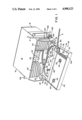
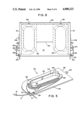
- FIG. 1 is a perspective view of interfacing apparatus of the present invention
- FIG. 2 is a partial exploded view of interfacing apparatus of the present invention
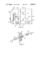
- FIG. 3 is an end view of interfacing apparatus of the present invention.
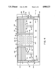
- FIG. 4 is a front view of interfacing apparatus of the present invention.
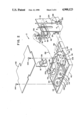
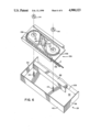
- FIG. 5 is a perspective view of a cassette of the present invention.
- FIG. 6 is a partial exploded view of a drawer for use with interfacing apparatus of the present invention.
- FIG. 7 is an exploded view of a connector panel for use with interfacing apparatus of the present invention.
- FIG. 8 is a plan view of interfacing apparatus of the present invention.
- FIGS. 1 and 2 depict an apparatus 2 for interfacing first optical fibers 4 of at least one first fiber optical cable 6 such as an external optical cable with second optical fibers 8 (not seen in FIG. 1) in the form of, for example, respective internal jumper patch cords.
- first fiber optical cable 6 such as an external optical cable
- second optical fibers 8 not seen in FIG. 1
- the apparatus 2 is useful in interfacing outside plant cable 6 with inside plant cords 10 connected to telephone transmission equipment, not shown.
- the apparatus 2 includes a housing comprising a base 12 and an opposing top 14. First opposing side wall 16 and second opposing side wall 18 are also provided extending vertically from base 12 to top 14. A rear wall 20 depicted in FIGS. 3 and 4 extends vertically from base 12 to top 14 and from first opposing side wall 16 to second opposing side wall 18. A forward opening 22 is provided opposite real wall 20. Means associated with the first and second side walls are provided for slideably supporting a drawer within the housing so that the drawer can be slid relative to the rear wall into the housing and out of the housing at the forward opening. For example, tracks 24 and 26 are provided in a known manner to facilitate such movement of a drawer 28.
- Drawer 28 is provided for sliding upon the slideably supporting means such as tracks 24 and 26.
- Drawer 28 forms an enclosure 30 including a bottom 32, first opposing side panel 34 and second opposing side panel 36 each extending vertically from bottom 32, a rear panel 38 including two sections extending vertically from bottom 32, and a front panel 40 opposite the rear panel 38 and extending vertically from bottom 32 and extending from the first opposing side wall 34 to the second opposing side wall 36.
- First means are positioned within the housing for storing the second optical fiber 8.
- such first means includes a plurality of removable cassettes 42.
- the housing includes a first plurality of opposing guides 44, 46 for guiding respective removable cassettes 42 into and out of the housing.
- Respective opposing guides 44, 46 are depicted as providing sets of tracks for the cassettes 42 to slide upon, respective pairs of tracks 44, 46 being stacked vertically towards the top 14, and extending towards the rear wall 20, of apparatus 2.
- the first plurality of opposing guides 44, 46 are positioned towards a side of the housing adjacent the first opposing wall 16.
- the housing also preferably includes a second plurality of opposing guides 48, 50 for guiding additional respective removable cassettes 42 into and out of the housing.
- Respective opposing guides 48, 50 are identical to guides 44, 46.
- respective opposing guides 48, 50 are depicted as providing sets of tracks for the additional cassettes 42 to slide upon, respective pairs of tracks 48, 50 also being stacked vertically towards the top 14, and extending towards the rear wall 20, of apparatus 2.
- the second plurality of opposing guides 48, 50 are positioned towards a side of the housing adjacent the second opposing wall 18.
- each respective cassette 42 includes opposing sides 52, 54 which slide upon respective of the opposing guides 44, 46 and 48, 50.
- each cassette 42 includes a rear edge 56 having a catch-like protuberance 58 extending therefrom.
- FIG. 4 which depicts some cassettes 42 in place and others removed, it will be observed that a rear abutment 58 is provided extending between respective opposing guides 44, 46 and between respective opposing guides 48, 50.
- Such rear abutment 58 includes a first plurality of apertures 60 each of which is positioned between a respective pair of opposing guides 44, 46. In the preferred embodiment apertures 60 are centered between respective guides 44, 46 as depicted in FIG.
- a similar second plurality of apertures 62 is provided each being positioned between a respective pair of opposing guides 48, 50 to receive a protuberanced 58 of a cassette 42 which is guided into the housing by sliding upon a pair of opposing guides 48, 50, in a like manner.
- each cassette 42 includes a hub 64 having flanges 66 and includes two pairs of spaced bosses 68, 70 each of which is designed in a known manner to pinch an optical fiber therebetween.
- Such structure allows an optical fiber 8 to be wound about the hub 64 to take up fiber slack and be held firmly in place by bosses 68, 70.
- Second means are provided positioned within the enclosure 30 for storing the first optical fibers and for storing a plurality of pigtails.
- such second means includes a first divider 72 which extends vertically from bottom 32, is parallel to rear panel 38, and is positioned midway between front panel 40 and rear panel 38.
- First opposing side panel 34 and second opposing side panel 36 include respective upper edges 74 and 76 spaced from the bottom 32 and having respective first opposing flanges 78 and 80 extending therefrom generally parallel to base 32 as depicted in FIG. 1.
- the rear panel which preferably is in the form of two sections 38, and the first divider 72, each include respective upper edges 82 and 84 spaced from bottom 32 and having respective second opposing flanges 86 and 88 extending therefrom.
- such second means also includes a second divider 90 which extends vertically from bottom 32, is parallel to the rear panel 38, and is positioned between the rear panel 38 and the first divider 72.
- the bottom 32 includes a first aperture 92 positioned in an area adjacent the first opposing side panel 34 and a second aperture 96 positioned in an area adjacent the second opposing side panel 36.
- a third means is provided positioned within the enclosure 30 for splicing an end of respective of the first optical fibers 4 to a corresponding first end of respective pigtails which are provided as described herein.
- such third means includes at least one splice tray 106.
- Such splice tray is attached to the bottom 32 of the drawer 28 in an area between the front panel and the first divider 72.
- the first divider extends from the first opposing side panel 34 towards the second opposing side panel 36, the first divider 72 being spaced from the second opposing side panel 36 at 108 to provide an area through which fibers 4 and the pigtails can extend to the splice tray 106.
- the splice tray 106 is attached to the drawer 28 by bolts 110 which extend vertically from bottom 32 of the drawer through apertures 112 in the splice tray 106 which is then held in place by nuts 114.
- a plurality of similar splice trays can be stacked upon one another when required as depicted in FIG. 6.
- Apparatus 2 includes fourth means positioned within the housing for optically connecting an end of respective of the second optical fibers 8 to a corresponding second end of respective pigtails provided as described herein.
- fourth means includes connector panels 116 which are positioned between the first plurality of opposing guides 44, 46 and the second plurality of opposing guides 48, 50 as depicted in FIG. 4, connector panels 116 being held in place by means of screws 118.
- Each connector panel includes a plurality of apertures 120 extending therethrough.
- Means are provided attached to each connector panel for optically connecting second optical fibers 8 to respective second ends of respective pigtails as described herein.
- adapters or attenuators of a type known in the art and generally depicted at 122 are provided into which the second optical fiber 8 and the pigtails can be plugged in a known manner.
- the outer sheath of cable 6 is stripped therefrom in a known manner to expose the buffered fibers 4 and strength member 4'. Subsequently the fibers 4, strength member 4', and cable 6 are inserted through a clamping member 124 positioned at second opposing side 18 and clamped firmly in place. The strength member 4' is then secured to a tire-off 126 in a known manner and the fibers 4 are routed through a cable entry 128, which extends through side 18, and onto to the drawer 28 via the entrance aperture 92, the fibers 4 being secured by tie wraps 130 as desired and the slack being taken up by wrapping the fibers 4 generally circularly in a counter-clockwise direction viewing FIG.
- the apparatus 2 within the confirms of flanges 78, 80, 86 and 88.
- the apparatus 2 can be provided with corresponding hardware and a second cable entry aperture 128 at the first opposing side 16 to increase the flexibility of the apparatus. Fibers extending from cable fastened at side 16 should be passed through entrance aperture 96.
- the entrance aperture located on the side of the apparatus opposite the cable entry port is the one used to route fibers.
- Fiber optical cables known as pigtails serve to bridge first optical fibers 4 and second optical fibers 8.
- a pigtail 132 is provided for each first fiber 4 to be connected to a corresponding second fiber 8.
- Each pigtail 132 includes a first end 134 and a second end 136. As depicted in FIG. 7, each end 136 is connected to an adapter or attenuator 122 at the rear of the connector panel 116 in a known manner.
- Each pigtail 132 is then routed onto drawer 28 via entrance aperture 92, the pigtails 132 being secured by tie wraps 130 as desired and the slack being taken up by wrapping the pigtails generally circularly in a clockwise direction viewing FIG.
- Each fiber 4 and pigtails 132 are then routed as depicted in FIGS. 2 and 6 through the space provided at 108, wrapped about take-up hubs 138 in a manner allowing fiber 4 and pigtail 132 to be optically coupled at a splice 140 in a known manner.
- each jumper patch cord includes an end 10 which is connected to the adapter or attenuator 122 at the front of the connector panel 116 in a known manner.
- a cover 142 is mounted upon drawer 28 by screws 144 and the drawer is closed. Then the front cover 146 is closed as depicted in FIG. 3 and locked in place.
- front cover 146 is removably hinged to the top of the housing in a known manner at hinges 148 which are positioned adjacent the forward opening of the housing.
- the first opposing side wall 16 and the second opposing side wall 18 can each include a plurality of optical fiber apertures in the form of cable entry ports 128. In this manner, access can be provided at the front of apparatus 2 or at the rear of apparatus 2 through an aperture in a respective opposing side wall.
- a fifth means can be provided removably attached to the first and second opposing side walls 16, 18 for preventing damage to any optical fibers extending through any of the apertures 128.
- fiber guards 150 can be attached to walls 16 and 18 in the vicinity of whatever aperture 128 is being used, by screwing the fiber guard to a mounting angle 152 by means of screws 154.
- Adjustable mounting brackets 156 are provided so that by removing screws 158 the brackets 156 can be positioned to accommodate various sizes of equipment or to accommodate a wall mounting.
- the apparatus of the present invention provides a means by which internal or inside optical fibers can be optically coupled to external or outside optical fibers using equipment which allows for testing and servicing from the front of apparatus which includes a stationary housing and moveable splice tray and cable storage unit. Optical fiber bending is controlled and attenuation is not a problem.
- the apparatus of the present invention is compact and can be mounted in standard equipment or upon a wall or the like, and yet is readily accessible. Fiber organization is improved so that users can access specific fibers quickly and easily with less risk of breakage and improved productivity.
Abstract
Description
Claims (20)
Priority Applications (4)
| Application Number | Priority Date | Filing Date | Title |
|---|---|---|---|
| US07/237,477 US4900123A (en) | 1988-08-29 | 1988-08-29 | 1550 nm fiber distribution panel |
| EP89115730A EP0356942B1 (en) | 1988-08-29 | 1989-08-25 | 1550NM fiber distribution panel |
| DE68920511T DE68920511T2 (en) | 1988-08-29 | 1989-08-25 | Distribution console for fiber optic cables. |
| JP1217645A JPH02111901A (en) | 1988-08-29 | 1989-08-25 | 1550nm optical fiber distributing panel |
Applications Claiming Priority (1)
| Application Number | Priority Date | Filing Date | Title |
|---|---|---|---|
| US07/237,477 US4900123A (en) | 1988-08-29 | 1988-08-29 | 1550 nm fiber distribution panel |
Publications (1)
| Publication Number | Publication Date |
|---|---|
| US4900123A true US4900123A (en) | 1990-02-13 |
Family
ID=22893883
Family Applications (1)
| Application Number | Title | Priority Date | Filing Date |
|---|---|---|---|
| US07/237,477 Expired - Lifetime US4900123A (en) | 1988-08-29 | 1988-08-29 | 1550 nm fiber distribution panel |
Country Status (4)
| Country | Link |
|---|---|
| US (1) | US4900123A (en) |
| EP (1) | EP0356942B1 (en) |
| JP (1) | JPH02111901A (en) |
| DE (1) | DE68920511T2 (en) |
Cited By (142)
| Publication number | Priority date | Publication date | Assignee | Title |
|---|---|---|---|---|
| US4976510A (en) * | 1989-11-20 | 1990-12-11 | Siecor Corporation | Communication outlet |
| US5071220A (en) * | 1989-05-11 | 1991-12-10 | L'etat Francais Represente Par Le Ministre Des Postes, Des Telecommunications Et Des L'espace (Centre National D'etudes Des Telecommunications) | Joint closure module and box for optical fiber cables |
| US5071211A (en) * | 1988-12-20 | 1991-12-10 | Northern Telecom Limited | Connector holders and distribution frame and connector holder assemblies for optical cable |
| US5092663A (en) * | 1990-05-21 | 1992-03-03 | Gte North Incorporated | Apparatus and method for maintaining slack of fiber optic cable or the like |
| US5204929A (en) * | 1991-09-04 | 1993-04-20 | Reliance Comm/Tec Corporation | Fiber patch panel |
| US5208894A (en) * | 1990-07-16 | 1993-05-04 | Adc Telecommunications, Inc. | Fiber optic splice cabinet |
| US5243679A (en) * | 1992-02-07 | 1993-09-07 | Gv Medical, Inc. | Optical fiber advancement, retraction and storage system |
| US5247603A (en) * | 1992-01-24 | 1993-09-21 | Minnesota Mining And Manufacturing Company | Fiber optic connection system with exchangeable cross-connect and interconnect cards |
| US5363467A (en) * | 1993-05-28 | 1994-11-08 | Minnesota Mining And Manufacturing Company | Compact fiber optic housing |
| US5367598A (en) * | 1993-10-21 | 1994-11-22 | Nec America, Inc. | Interface chassis for fiber optic transport system |
| US5408570A (en) * | 1994-06-30 | 1995-04-18 | Minnesota Mining And Manufacturing Company | Fiber optic housing with low part count |
| US5434944A (en) * | 1991-06-18 | 1995-07-18 | British Telecommunications Public Limited Company | Optical fibre connection equipment |
| US5446822A (en) * | 1993-05-28 | 1995-08-29 | Minnesota Mining And Manufacturing Company | Connector clip for fiber optic housing |
| US5459808A (en) * | 1994-06-30 | 1995-10-17 | Minnesota Mining And Manufacturing Company | Fiber optic housing with removable chassis and method using same |
| US5490229A (en) * | 1993-12-08 | 1996-02-06 | At&T Ipm Corp. | Slidably mounted optical fiber distribution tray |
| US5511144A (en) * | 1994-06-13 | 1996-04-23 | Siecor Corporation | Optical distribution frame |
| US5613030A (en) * | 1995-05-15 | 1997-03-18 | The Whitaker Corporation | High density fiber optic interconnection enclosure |
| US5724469A (en) * | 1996-01-26 | 1998-03-03 | Ortronics, Inc. | Adjustable fiber storage plate |
| US5740298A (en) * | 1993-09-08 | 1998-04-14 | N.V. Raychem S.A. | Optical fibre organizer |
| US5946440A (en) * | 1997-11-17 | 1999-08-31 | Adc Telecommunications, Inc. | Optical fiber cable management device |
| US5975769A (en) * | 1997-07-08 | 1999-11-02 | Telect, Inc. | Universal fiber optic module system |
| US6181861B1 (en) * | 1997-02-14 | 2001-01-30 | Alcatel | Arrangement for branching a telecommunications cable containing several stranded elements with optical fibers |
| US6201919B1 (en) | 1998-12-16 | 2001-03-13 | Adc Telecommunications, Inc | Fiber distribution frame |
| US6215937B1 (en) | 1998-09-24 | 2001-04-10 | Thomas & Betts International, Inc. | Adjustable fiber optic strand storage unit |
| US6418262B1 (en) * | 2000-03-13 | 2002-07-09 | Adc Telecommunications, Inc. | Fiber distribution frame with fiber termination blocks |
| US20020150372A1 (en) * | 2001-02-12 | 2002-10-17 | Fiber Optic Network Solutions Corp. | Optical fiber enclosure system |
| US6501898B1 (en) * | 1999-05-27 | 2002-12-31 | Telefonaktiebolaget Lm Ericsson (Publ) | Handling of optical fibres in confined or limited spaces |
| US6515227B1 (en) | 2002-05-24 | 2003-02-04 | Alcoa Fujikura Limited | Fiber optic cable management enclosure with integral bend radius control |
| US20030047107A1 (en) * | 2000-02-07 | 2003-03-13 | Thomas Dean Te Wera | Portable ski tow |
| US20030103750A1 (en) * | 2001-11-30 | 2003-06-05 | Laporte Richard B. | Distribution terminal for network access point |
| US6674952B2 (en) | 2001-04-30 | 2004-01-06 | Telect, Inc. | Fiber optic cable bend radius protection system |
| US6694084B1 (en) * | 2000-06-23 | 2004-02-17 | Mitsubishi Denki Kabushiki Kaisha | Optical cable excess handling unit and optical cable wiring method |
| US20040120680A1 (en) * | 2002-10-11 | 2004-06-24 | Michel Dillat | Array of fiber optic splicing cassettes |
| US20040120681A1 (en) * | 2002-10-11 | 2004-06-24 | Bohle Klaus Wemer | Drawer for the management of optical fibers |
| US6819857B2 (en) | 2001-10-12 | 2004-11-16 | Adc Telecommunications, Inc. | Rotating vertical fiber tray and methods |
| US20050111810A1 (en) * | 2003-11-26 | 2005-05-26 | Giraud William J. | Connector housing for a communication network |
| US20050111809A1 (en) * | 2003-11-26 | 2005-05-26 | Giraud William J. | Connector housing having a sliding tray with a hingeable portion |
| US20050129379A1 (en) * | 2003-11-17 | 2005-06-16 | Fiber Optic Network Solutions Corporation | Systems and methods for optical fiber distribution and management |
| US6944387B2 (en) | 2001-04-30 | 2005-09-13 | Telect, Inc. | Fiber optic connector tray system |
| US20050207711A1 (en) * | 2004-03-19 | 2005-09-22 | Vo Chanh C | Optical termination pedestal |
| US20060018622A1 (en) * | 2004-07-22 | 2006-01-26 | Caveney Jack E | Front access punch down patch panel |
| US20060115223A1 (en) * | 2004-11-30 | 2006-06-01 | Advantest Corporation | Test apparatus, optical coupler and method of manufacturing same |
| US20060215980A1 (en) * | 2005-03-24 | 2006-09-28 | Yilmaz Bayazit | Splice tray arrangement |
| US20070047891A1 (en) * | 2005-08-25 | 2007-03-01 | Yilmaz Bayazit | Stackable splice chip device |
| US20070047892A1 (en) * | 2005-08-25 | 2007-03-01 | Yilmaz Bayazit | Splice chip device |
| US20070165995A1 (en) * | 2005-08-30 | 2007-07-19 | Randy Reagan | Fiber distribution hub with modular termination blocks |
| US20070172192A1 (en) * | 2005-12-02 | 2007-07-26 | Adc Telecommunications, Inc. | Splice tray arrangement |
| US20070192817A1 (en) * | 2006-02-13 | 2007-08-16 | Landry Edward T | Fiber distribution hub with outside accessible grounding terminals |
| US20080008437A1 (en) * | 2003-11-17 | 2008-01-10 | Fiber Optics Network Solutions Corp. | Hinged parking in fiber distribution hubs |
| US20080019655A1 (en) * | 2004-06-18 | 2008-01-24 | Adc Telecommunications, Inc. | Fiber Optic Splitter |
| US20080025683A1 (en) * | 2006-07-26 | 2008-01-31 | Adam Murano | Secure fiber optic network cassette assembly |
| US20080031585A1 (en) * | 2006-05-04 | 2008-02-07 | Solheid James J | Fiber Distribution Hub with Swing Frame and Wrap-Around Doors |
| US20080050083A1 (en) * | 2006-08-25 | 2008-02-28 | Frazier Brent M | Fiber optic housing assembly for fiber optic connections comprising pivotable portion |
| US20080075411A1 (en) * | 2003-07-02 | 2008-03-27 | Adc Telecommunications, Inc. | Telecommunications connection cabinet |
| US20080112681A1 (en) * | 2004-02-06 | 2008-05-15 | Battey Jennifer A | Optical connection closure having at least one connector port |
| US20080145013A1 (en) * | 2006-12-13 | 2008-06-19 | Alejandro Raigoza Escoto | High density fiber optic hardware |
| US7407330B2 (en) | 2003-06-30 | 2008-08-05 | Adc Telecommunications, Inc. | Fiber optic connector holder and method |
| US20080205844A1 (en) * | 2007-02-28 | 2008-08-28 | Guy Castonguay | Fiber optic splice trays |
| US20080298763A1 (en) * | 2007-05-31 | 2008-12-04 | Mark David Appenzeller | Telecommunications housing with optical fiber management |
| US20090060439A1 (en) * | 2007-09-05 | 2009-03-05 | Terry Dean Cox | Fiber optic terminal assembly |
| US20090211171A1 (en) * | 2008-02-25 | 2009-08-27 | Timothy Frederick Summers | Multi-dwelling unit multipurpose signal distribution apparatus |
| US20090263096A1 (en) * | 2007-11-21 | 2009-10-22 | Adc Telecommunications, Inc. | Fiber distribution hub with multiple configurations |
| US20100054687A1 (en) * | 2006-12-05 | 2010-03-04 | Li Ye | Cable slack handling device |
| US20100054668A1 (en) * | 2008-08-27 | 2010-03-04 | Keith Nelson | Fiber optic adapter with integrally molded ferrule alignment structure |
| US7720343B2 (en) | 2006-02-13 | 2010-05-18 | Adc Telecommunications, Inc. | Fiber distribution hub with swing frame and modular termination panels |
| US20100215330A1 (en) * | 2009-02-24 | 2010-08-26 | Bartlomiej Sokolowski | Holding Device for a Cable or an Assembly for Use With a Cable |
| US20100220967A1 (en) * | 2009-02-27 | 2010-09-02 | Cooke Terry L | Hinged Fiber Optic Module Housing and Module |
| US20100247053A1 (en) * | 2009-03-31 | 2010-09-30 | Cowen Andrew P | Removably mountable fiber optic terminal |
| US20100322582A1 (en) * | 2009-06-19 | 2010-12-23 | Cooke Terry L | High Capacity Fiber Optic Connection Infrastructure Apparatus |
| US20100322581A1 (en) * | 2009-06-19 | 2010-12-23 | Cooke Terry L | High Fiber Optic Cable Packing Density Apparatus |
| US20100322580A1 (en) * | 2009-06-22 | 2010-12-23 | Beamon Hubert B | Fiber Optic Cable Parking Device |
| US20100322583A1 (en) * | 2009-06-19 | 2010-12-23 | Cooke Terry L | High Density and Bandwidth Fiber Optic Apparatuses and Related Equipment and Methods |
| US20100322579A1 (en) * | 2009-06-19 | 2010-12-23 | Cooke Terry L | High-density fiber optic modules and module housings and related equipment |
| US7889961B2 (en) | 2008-03-27 | 2011-02-15 | Corning Cable Systems Llc | Compact, high-density adapter module, housing assembly and frame assembly for optical fiber telecommunications |
| US20110058784A1 (en) * | 1999-03-01 | 2011-03-10 | Adc Telecommunications, Inc. | Optical fiber distribution frame with outside plant enclosure |
| US7941026B2 (en) | 2005-03-31 | 2011-05-10 | Adc Telecommunications, Inc. | Adapter block including connector storage |
| US20110129185A1 (en) * | 2009-11-30 | 2011-06-02 | Lewallen C Paul | Articulated Strain Relief Boot on a Fiber Optic Module and Associated Methods |
| US20110150407A1 (en) * | 2009-12-18 | 2011-06-23 | Beamon Hubert B | Rotary Locking Apparatus for Fiber Optic Equipment Trays and Related Methods |
| US20110188815A1 (en) * | 2010-02-04 | 2011-08-04 | Blackwell Jr Chois A | Optical interface cards, assemblies, and related methods, suited for installation and use in antenna system equipment |
| US20110211799A1 (en) * | 2008-10-27 | 2011-09-01 | Mark Edward Conner | Variably configurable and modular local convergence point |
| US20110222831A1 (en) * | 2008-10-09 | 2011-09-15 | Songhua Cao | Fiber optic terminal having adapter panel supporting both input and output fibers from an optical splitter |
| US20110235985A1 (en) * | 2010-03-26 | 2011-09-29 | Cote Monique L | Movable Adapter Panel |
| US20110317971A1 (en) * | 2008-05-12 | 2011-12-29 | Adc Communications (Shanghai) Co., Ltd. | Cable management panel |
| US8208781B1 (en) * | 2009-12-03 | 2012-06-26 | Adtran, Inc. | Fiber optic connector panel |
| US8417074B2 (en) | 2008-11-21 | 2013-04-09 | Adc Telecommunications, Inc. | Fiber optic telecommunications module |
| US8467651B2 (en) | 2009-09-30 | 2013-06-18 | Ccs Technology Inc. | Fiber optic terminals configured to dispose a fiber optic connection panel(s) within an optical fiber perimeter and related methods |
| US8538226B2 (en) | 2009-05-21 | 2013-09-17 | Corning Cable Systems Llc | Fiber optic equipment guides and rails configured with stopping position(s), and related equipment and methods |
| US8542973B2 (en) | 2010-04-23 | 2013-09-24 | Ccs Technology, Inc. | Fiber optic distribution device |
| USRE44758E1 (en) | 2003-03-20 | 2014-02-11 | Adc Telecommunications, Inc. | Optical fiber interconnect cabinets, termination modules and fiber connectivity management for the same |
| US8660397B2 (en) | 2010-04-30 | 2014-02-25 | Corning Cable Systems Llc | Multi-layer module |
| US8662760B2 (en) | 2010-10-29 | 2014-03-04 | Corning Cable Systems Llc | Fiber optic connector employing optical fiber guide member |
| US8699838B2 (en) | 2009-05-14 | 2014-04-15 | Ccs Technology, Inc. | Fiber optic furcation module |
| US20140105557A1 (en) * | 2012-10-11 | 2014-04-17 | Grzegorz Fabrykowski | System comprising a plurality of distribution devices and distribution device |
| US8705926B2 (en) | 2010-04-30 | 2014-04-22 | Corning Optical Communications LLC | Fiber optic housings having a removable top, and related components and methods |
| US8718436B2 (en) | 2010-08-30 | 2014-05-06 | Corning Cable Systems Llc | Methods, apparatuses for providing secure fiber optic connections |
| US8792767B2 (en) | 2010-04-16 | 2014-07-29 | Ccs Technology, Inc. | Distribution device |
| US8879881B2 (en) | 2010-04-30 | 2014-11-04 | Corning Cable Systems Llc | Rotatable routing guide and assembly |
| US8953924B2 (en) | 2011-09-02 | 2015-02-10 | Corning Cable Systems Llc | Removable strain relief brackets for securing fiber optic cables and/or optical fibers to fiber optic equipment, and related assemblies and methods |
| US8958679B2 (en) | 2010-03-02 | 2015-02-17 | Tyco Electronics Services Gmbh | Fibre-optic telecommunications module |
| US8965168B2 (en) | 2010-04-30 | 2015-02-24 | Corning Cable Systems Llc | Fiber management devices for fiber optic housings, and related components and methods |
| US8989547B2 (en) | 2011-06-30 | 2015-03-24 | Corning Cable Systems Llc | Fiber optic equipment assemblies employing non-U-width-sized housings and related methods |
| US8985862B2 (en) | 2013-02-28 | 2015-03-24 | Corning Cable Systems Llc | High-density multi-fiber adapter housings |
| US8995812B2 (en) | 2012-10-26 | 2015-03-31 | Ccs Technology, Inc. | Fiber optic management unit and fiber optic distribution device |
| US9004778B2 (en) | 2012-06-29 | 2015-04-14 | Corning Cable Systems Llc | Indexable optical fiber connectors and optical fiber connector arrays |
| US9008485B2 (en) | 2011-05-09 | 2015-04-14 | Corning Cable Systems Llc | Attachment mechanisms employed to attach a rear housing section to a fiber optic housing, and related assemblies and methods |
| US9022814B2 (en) | 2010-04-16 | 2015-05-05 | Ccs Technology, Inc. | Sealing and strain relief device for data cables |
| US9042702B2 (en) | 2012-09-18 | 2015-05-26 | Corning Cable Systems Llc | Platforms and systems for fiber optic cable attachment |
| US9038832B2 (en) | 2011-11-30 | 2015-05-26 | Corning Cable Systems Llc | Adapter panel support assembly |
| US9049500B2 (en) | 2012-08-31 | 2015-06-02 | Corning Cable Systems Llc | Fiber optic terminals, systems, and methods for network service management |
| US20150171609A1 (en) * | 2009-08-06 | 2015-06-18 | 3M Innovative Properties Company | System and method for providing final drop in a living unit in a building |
| US9075217B2 (en) | 2010-04-30 | 2015-07-07 | Corning Cable Systems Llc | Apparatuses and related components and methods for expanding capacity of fiber optic housings |
| US9116324B2 (en) | 2010-10-29 | 2015-08-25 | Corning Cable Systems Llc | Stacked fiber optic modules and fiber optic equipment configured to support stacked fiber optic modules |
| US9146362B2 (en) | 2012-09-21 | 2015-09-29 | Adc Telecommunications, Inc. | Insertion and removal tool for a fiber optic ferrule alignment sleeve |
| US9146374B2 (en) | 2012-09-28 | 2015-09-29 | Adc Telecommunications, Inc. | Rapid deployment packaging for optical fiber |
| US9213161B2 (en) | 2010-11-05 | 2015-12-15 | Corning Cable Systems Llc | Fiber body holder and strain relief device |
| US9219546B2 (en) | 2011-12-12 | 2015-12-22 | Corning Optical Communications LLC | Extremely high frequency (EHF) distributed antenna systems, and related components and methods |
| US9223094B2 (en) | 2012-10-05 | 2015-12-29 | Tyco Electronics Nederland Bv | Flexible optical circuit, cassettes, and methods |
| US9250409B2 (en) | 2012-07-02 | 2016-02-02 | Corning Cable Systems Llc | Fiber-optic-module trays and drawers for fiber-optic equipment |
| US9279951B2 (en) | 2010-10-27 | 2016-03-08 | Corning Cable Systems Llc | Fiber optic module for limited space applications having a partially sealed module sub-assembly |
| US9435975B2 (en) | 2013-03-15 | 2016-09-06 | Commscope Technologies Llc | Modular high density telecommunications frame and chassis system |
| US9494758B2 (en) | 2014-04-03 | 2016-11-15 | Commscope Technologies Llc | Fiber optic distribution system |
| US9519118B2 (en) | 2010-04-30 | 2016-12-13 | Corning Optical Communications LLC | Removable fiber management sections for fiber optic housings, and related components and methods |
| US9535229B2 (en) | 2011-10-07 | 2017-01-03 | Commscope Technologies Llc | Fiber optic cassette, system, and method |
| CN106324777A (en) * | 2016-11-01 | 2017-01-11 | 南京普天天纪楼宇智能有限公司 | High-density optical fiber branch box |
| US9547144B2 (en) | 2010-03-16 | 2017-01-17 | Corning Optical Communications LLC | Fiber optic distribution network for multiple dwelling units |
| US9547145B2 (en) | 2010-10-19 | 2017-01-17 | Corning Optical Communications LLC | Local convergence point for multiple dwelling unit fiber optic distribution network |
| US9632270B2 (en) | 2010-04-30 | 2017-04-25 | Corning Optical Communications LLC | Fiber optic housings configured for tool-less assembly, and related components and methods |
| US9645317B2 (en) | 2011-02-02 | 2017-05-09 | Corning Optical Communications LLC | Optical backplane extension modules, and related assemblies suitable for establishing optical connections to information processing modules disposed in equipment racks |
| US9720195B2 (en) | 2010-04-30 | 2017-08-01 | Corning Optical Communications LLC | Apparatuses and related components and methods for attachment and release of fiber optic housings to and from an equipment rack |
| US9851524B2 (en) | 2014-01-28 | 2017-12-26 | Commscope Technologies Llc | Slidable fiber optic connection module with cable slack management |
| US10094996B2 (en) | 2008-08-29 | 2018-10-09 | Corning Optical Communications, Llc | Independently translatable modules and fiber optic equipment trays in fiber optic equipment |
| US10110307B2 (en) | 2012-03-02 | 2018-10-23 | Corning Optical Communications LLC | Optical network units (ONUs) for high bandwidth connectivity, and related components and methods |
| US10254497B2 (en) * | 2015-04-13 | 2019-04-09 | Commscope Technologies Llc | Telecommunications chassis and module |
| US10302874B2 (en) | 2015-05-15 | 2019-05-28 | Commscope Telecommunications (Shanghai) Co., Ltd. | Alignment sleeve assembly and fiber optic adapter |
| US11294136B2 (en) | 2008-08-29 | 2022-04-05 | Corning Optical Communications LLC | High density and bandwidth fiber optic apparatuses and related equipment and methods |
| US20220128785A1 (en) * | 2019-04-17 | 2022-04-28 | Afl Ig Llc | Patch panel with lifting cassette removal |
| US11372165B2 (en) | 2011-09-12 | 2022-06-28 | Commscope Technologies Llc | Flexible lensed optical interconnect device for signal distribution |
| US11409068B2 (en) | 2017-10-02 | 2022-08-09 | Commscope Technologies Llc | Fiber optic circuit and preparation method |
| US11575228B2 (en) | 2020-07-27 | 2023-02-07 | Raytheon Company | Helical strain relief for electrical conductors, fiber optic cables, or other cables |
| US11592628B2 (en) | 2012-09-28 | 2023-02-28 | Commscope Technologies Llc | Fiber optic cassette |
| US20230141550A1 (en) * | 2021-11-10 | 2023-05-11 | Opterna Am, Inc. | Rack mountable panel for optimizing slack storage and management of optical fiber cables |
| WO2024072990A1 (en) * | 2022-09-29 | 2024-04-04 | viaPhoton, Inc. | Miniature network interface device |
Families Citing this family (47)
| Publication number | Priority date | Publication date | Assignee | Title |
|---|---|---|---|---|
| US3475480A (en) * | 1966-05-17 | 1969-10-28 | Thompson Chem Co Hayward | Synthesis of aromatic nitriles by nitrilizing halogenated intermediates |
| GB2241591A (en) * | 1990-02-28 | 1991-09-04 | Optical Data Communications Li | Mounting frames for fibre optic or electrical cable organiser trays |
| US5142607A (en) * | 1990-03-20 | 1992-08-25 | Rittal-Werk Rudolf Loh Gmbh & Co. Kg | Splice box for optical wave guide |
| EP0501336B1 (en) * | 1991-02-27 | 1996-06-05 | Siemens Aktiengesellschaft | Separating housing for lightwave guides |
| CH686267A5 (en) * | 1993-07-30 | 1996-02-15 | G & B Elektro Ag | Stackable cable end termination for optical fibres |
| GB9318654D0 (en) * | 1993-09-08 | 1993-10-27 | Raychem Sa Nv | Optical fibre organizer |
| FR2710419B1 (en) * | 1993-09-24 | 1995-12-15 | Blanchard Anne Marie | Connection device for optical fibers. |
| GB2282457B (en) * | 1993-09-29 | 1996-10-02 | Pirelli General Plc | An assembly for use in connecting optical fibres |
| US5402515A (en) * | 1994-03-01 | 1995-03-28 | Minnesota Mining And Manufacturing Company | Fiber distribution frame system, cabinets, trays and fiber optic connector couplings |
| GB2291209B (en) * | 1994-06-20 | 1998-04-01 | Pirelli General Plc | Optical fibre organiser having guiding tube for optical fibre |
| US5481639A (en) * | 1994-10-28 | 1996-01-02 | At&T Corp. | Compact closure for optical fiber cable |
| JP2931219B2 (en) * | 1994-11-15 | 1999-08-09 | 日本電信電話株式会社 | Module for terminating optical fiber cable |
| GB2298496B (en) * | 1995-02-28 | 1998-06-03 | Bowthorpe Plc | Optical fibre splice storage arrangements |
| FR2733843B1 (en) * | 1995-05-03 | 1997-05-30 | Alcatel Submarcom | ORGANIZER DEVICE FOR CONNECTING FIBER OPTIC CABLES AND JUNCTION BOX FOR OPTICAL CABLES |
| US5825962A (en) * | 1996-12-31 | 1998-10-20 | Siecor Corporation | Optical fiber splice housing |
| US6438310B1 (en) | 2000-01-24 | 2002-08-20 | Adc Telecommunications, Inc. | Cable management panel with sliding drawer |
| US6504988B1 (en) * | 2000-01-24 | 2003-01-07 | Adc Telecommunications, Inc. | Cable management panel with sliding drawer |
| JP4524436B2 (en) * | 2001-04-25 | 2010-08-18 | ネッツエスアイ東洋株式会社 | Extra length optical cable processing structure |
| DE102004033229A1 (en) * | 2004-07-08 | 2006-01-26 | Ewe Ag | Device for linking at least one branch optical waveguide to a main optical waveguide |
| US9002166B2 (en) | 2011-10-07 | 2015-04-07 | Adc Telecommunications, Inc. | Slidable fiber optic connection module with cable slack management |
| US9170391B2 (en) | 2011-10-07 | 2015-10-27 | Adc Telecommunications, Inc. | Slidable fiber optic connection module with cable slack management |
| WO2013052854A2 (en) | 2011-10-07 | 2013-04-11 | Adc Telecommunications, Inc. | Slidable fiber optic connection module with cable slack management |
| US9075203B2 (en) | 2012-01-17 | 2015-07-07 | Adc Telecommunications, Inc. | Fiber optic adapter block |
| US10082636B2 (en) | 2012-09-21 | 2018-09-25 | Commscope Technologies Llc | Slidable fiber optic connection module with cable slack management |
| US9195021B2 (en) * | 2012-09-21 | 2015-11-24 | Adc Telecommunications, Inc. | Slidable fiber optic connection module with cable slack management |
| ES2953122T3 (en) | 2013-01-29 | 2023-11-08 | CommScope Connectivity Belgium BVBA | Fiber optic distribution system |
| US9128262B2 (en) | 2013-02-05 | 2015-09-08 | Adc Telecommunications, Inc. | Slidable telecommunications tray with cable slack management |
| WO2014133943A1 (en) | 2013-02-27 | 2014-09-04 | Adc Telecommunications, Inc. | Slidable fiber optic connection module with cable slack management |
| NZ713590A (en) | 2013-04-24 | 2018-09-28 | CommScope Connectivity Belgium BVBA | Universal mounting mechanism for mounting a telecommunications chassis to a telecommunications fixture |
| WO2014173930A1 (en) | 2013-04-24 | 2014-10-30 | Tyco Electronics Raychem Bvba | Optical fiber distribution system |
| CA2954776C (en) | 2014-07-10 | 2023-05-16 | Corning Optical Communications LLC | Optical fiber distribution hub with fiber routing structures |
| US10247886B2 (en) | 2014-12-10 | 2019-04-02 | Commscope Technologies Llc | Fiber optic cable slack management module |
| WO2016156611A1 (en) | 2015-04-03 | 2016-10-06 | CommScope Connectivity Belgium BVBA | Telecommunications distribution elements |
| WO2017184501A1 (en) | 2016-04-19 | 2017-10-26 | Commscope, Inc. Of North Carolina | Door assembly for a telecommunications chassis with a combination hinge structure |
| EP3446554B1 (en) | 2016-04-19 | 2020-12-02 | CommScope, Inc. of North Carolina | Telecommunications chassis with slidable trays |
| CN109196401A (en) * | 2016-05-18 | 2019-01-11 | 康普连通比利时私人有限公司 | Cable slack portion stores equipment |
| ES2929573T3 (en) | 2017-02-23 | 2022-11-30 | Commscope Technologies Llc | High Fiber Count Termination Device |
| WO2018226959A1 (en) | 2017-06-07 | 2018-12-13 | Commscope Technologies Llc | Fiber optic adapter and cassette |
| US11385429B2 (en) | 2017-10-18 | 2022-07-12 | Commscope Technologies Llc | Fiber optic connection cassette |
| EP3759535A4 (en) | 2018-02-28 | 2021-11-10 | CommScope Technologies LLC | Packaging assembly for telecommunications equipment |
| US11256054B2 (en) | 2018-04-16 | 2022-02-22 | Commscope Technologies Llc | Adapter structure |
| US11635578B2 (en) | 2018-04-17 | 2023-04-25 | CommScope Connectivity Belgium BVBA | Telecommunications distribution elements |
| EP3845044B1 (en) | 2018-08-31 | 2023-02-15 | CommScope Connectivity Belgium BVBA | Frame assemblies for optical fiber distribution elements |
| EP3844972B1 (en) | 2018-08-31 | 2022-08-03 | CommScope Connectivity Belgium BVBA | Frame assemblies for optical fiber distribution elements |
| EP3844973A1 (en) | 2018-08-31 | 2021-07-07 | CommScope Connectivity Belgium BVBA | Frame assemblies for optical fiber distribution elements |
| WO2020043909A1 (en) | 2018-08-31 | 2020-03-05 | CommScope Connectivity Belgium BVBA | Frame assemblies for optical fiber distribution elements |
| EP3914947A1 (en) | 2019-01-25 | 2021-12-01 | CommScope Connectivity Belgium BVBA | Frame assemblies for optical fiber distribution elements |
Citations (7)
| Publication number | Priority date | Publication date | Assignee | Title |
|---|---|---|---|---|
| US4266853A (en) * | 1979-03-12 | 1981-05-12 | Northern Telecom Limited | Device for organizing optical fibers and the like |
| US4595255A (en) * | 1983-08-24 | 1986-06-17 | Fiberlan, Inc. | Optical fiber wiring center |
| US4679896A (en) * | 1985-09-27 | 1987-07-14 | Preformed Line Products Company | Optical fiber splice organizer |
| US4702551A (en) * | 1984-10-11 | 1987-10-27 | Reliance Comm/Tec Corporation | Method and apparatus for handling and storing cabled spliced ends of fiber optics |
| US4717231A (en) * | 1983-01-05 | 1988-01-05 | Vincent Dewez | Interconnecting and distributing box for optical fibers |
| US4790626A (en) * | 1984-12-28 | 1988-12-13 | Les Cables De Lyon | Connection between an optical fiber cable and a junction box |
| US4793682A (en) * | 1988-01-11 | 1988-12-27 | Gte Products Corporation | Fiber optic splice and fiber holder and housing therefor |
Family Cites Families (5)
| Publication number | Priority date | Publication date | Assignee | Title |
|---|---|---|---|---|
| CA1249741A (en) * | 1984-10-25 | 1989-02-07 | Michael J. Donaldson | Optical cable terminating equipment |
| GB8514389D0 (en) * | 1985-06-07 | 1985-07-10 | Telephone Cables Ltd | Joint closure housing |
| DE3528246A1 (en) * | 1985-08-07 | 1987-02-12 | Standard Elektrik Lorenz Ag | Rack for telecommunications technology |
| CA1275193C (en) * | 1985-09-17 | 1990-10-16 | Mark Anton | Optical fiber distribution apparatus |
| DE3537889A1 (en) * | 1985-10-24 | 1987-04-30 | Sedlbauer Wilhelm Gmbh | Distributor rack for fibre-optic cables |
-
1988
- 1988-08-29 US US07/237,477 patent/US4900123A/en not_active Expired - Lifetime
-
1989
- 1989-08-25 JP JP1217645A patent/JPH02111901A/en active Pending
- 1989-08-25 EP EP89115730A patent/EP0356942B1/en not_active Expired - Lifetime
- 1989-08-25 DE DE68920511T patent/DE68920511T2/en not_active Expired - Fee Related
Patent Citations (7)
| Publication number | Priority date | Publication date | Assignee | Title |
|---|---|---|---|---|
| US4266853A (en) * | 1979-03-12 | 1981-05-12 | Northern Telecom Limited | Device for organizing optical fibers and the like |
| US4717231A (en) * | 1983-01-05 | 1988-01-05 | Vincent Dewez | Interconnecting and distributing box for optical fibers |
| US4595255A (en) * | 1983-08-24 | 1986-06-17 | Fiberlan, Inc. | Optical fiber wiring center |
| US4702551A (en) * | 1984-10-11 | 1987-10-27 | Reliance Comm/Tec Corporation | Method and apparatus for handling and storing cabled spliced ends of fiber optics |
| US4790626A (en) * | 1984-12-28 | 1988-12-13 | Les Cables De Lyon | Connection between an optical fiber cable and a junction box |
| US4679896A (en) * | 1985-09-27 | 1987-07-14 | Preformed Line Products Company | Optical fiber splice organizer |
| US4793682A (en) * | 1988-01-11 | 1988-12-27 | Gte Products Corporation | Fiber optic splice and fiber holder and housing therefor |
Cited By (336)
| Publication number | Priority date | Publication date | Assignee | Title |
|---|---|---|---|---|
| US5071211A (en) * | 1988-12-20 | 1991-12-10 | Northern Telecom Limited | Connector holders and distribution frame and connector holder assemblies for optical cable |
| US5071220A (en) * | 1989-05-11 | 1991-12-10 | L'etat Francais Represente Par Le Ministre Des Postes, Des Telecommunications Et Des L'espace (Centre National D'etudes Des Telecommunications) | Joint closure module and box for optical fiber cables |
| US4976510A (en) * | 1989-11-20 | 1990-12-11 | Siecor Corporation | Communication outlet |
| US5092663A (en) * | 1990-05-21 | 1992-03-03 | Gte North Incorporated | Apparatus and method for maintaining slack of fiber optic cable or the like |
| US5208894A (en) * | 1990-07-16 | 1993-05-04 | Adc Telecommunications, Inc. | Fiber optic splice cabinet |
| US5434944A (en) * | 1991-06-18 | 1995-07-18 | British Telecommunications Public Limited Company | Optical fibre connection equipment |
| US5204929A (en) * | 1991-09-04 | 1993-04-20 | Reliance Comm/Tec Corporation | Fiber patch panel |
| US5247603A (en) * | 1992-01-24 | 1993-09-21 | Minnesota Mining And Manufacturing Company | Fiber optic connection system with exchangeable cross-connect and interconnect cards |
| US5243679A (en) * | 1992-02-07 | 1993-09-07 | Gv Medical, Inc. | Optical fiber advancement, retraction and storage system |
| US5363467A (en) * | 1993-05-28 | 1994-11-08 | Minnesota Mining And Manufacturing Company | Compact fiber optic housing |
| US5446822A (en) * | 1993-05-28 | 1995-08-29 | Minnesota Mining And Manufacturing Company | Connector clip for fiber optic housing |
| US5740298A (en) * | 1993-09-08 | 1998-04-14 | N.V. Raychem S.A. | Optical fibre organizer |
| US5367598A (en) * | 1993-10-21 | 1994-11-22 | Nec America, Inc. | Interface chassis for fiber optic transport system |
| US5490229A (en) * | 1993-12-08 | 1996-02-06 | At&T Ipm Corp. | Slidably mounted optical fiber distribution tray |
| US5511144A (en) * | 1994-06-13 | 1996-04-23 | Siecor Corporation | Optical distribution frame |
| US5459808A (en) * | 1994-06-30 | 1995-10-17 | Minnesota Mining And Manufacturing Company | Fiber optic housing with removable chassis and method using same |
| US5408570A (en) * | 1994-06-30 | 1995-04-18 | Minnesota Mining And Manufacturing Company | Fiber optic housing with low part count |
| US5613030A (en) * | 1995-05-15 | 1997-03-18 | The Whitaker Corporation | High density fiber optic interconnection enclosure |
| US5724469A (en) * | 1996-01-26 | 1998-03-03 | Ortronics, Inc. | Adjustable fiber storage plate |
| US6181861B1 (en) * | 1997-02-14 | 2001-01-30 | Alcatel | Arrangement for branching a telecommunications cable containing several stranded elements with optical fibers |
| US5975769A (en) * | 1997-07-08 | 1999-11-02 | Telect, Inc. | Universal fiber optic module system |
| US5946440A (en) * | 1997-11-17 | 1999-08-31 | Adc Telecommunications, Inc. | Optical fiber cable management device |
| US6215937B1 (en) | 1998-09-24 | 2001-04-10 | Thomas & Betts International, Inc. | Adjustable fiber optic strand storage unit |
| US6201919B1 (en) | 1998-12-16 | 2001-03-13 | Adc Telecommunications, Inc | Fiber distribution frame |
| US8768134B2 (en) | 1999-03-01 | 2014-07-01 | Adc Telecommunications, Inc. | Optical fiber distribution frame with outside plant enclosure |
| US9429728B2 (en) | 1999-03-01 | 2016-08-30 | Commscope Technologies Llc | Optical fiber distribution frame with outside plant enclosure |
| US10067309B2 (en) | 1999-03-01 | 2018-09-04 | Commscope Technologies Llc | Optical fiber distribution frame with outside plant enclosure |
| US20110058784A1 (en) * | 1999-03-01 | 2011-03-10 | Adc Telecommunications, Inc. | Optical fiber distribution frame with outside plant enclosure |
| US9810868B2 (en) | 1999-03-01 | 2017-11-07 | Commscope Technologies Llc | Optical fiber distribution frame with outside plant enclosure |
| US8019192B2 (en) | 1999-03-01 | 2011-09-13 | Adc Telecommunications, Inc. | Optical fiber distribution frame with outside plant enclosure |
| US6501898B1 (en) * | 1999-05-27 | 2002-12-31 | Telefonaktiebolaget Lm Ericsson (Publ) | Handling of optical fibres in confined or limited spaces |
| US20030047107A1 (en) * | 2000-02-07 | 2003-03-13 | Thomas Dean Te Wera | Portable ski tow |
| US6418262B1 (en) * | 2000-03-13 | 2002-07-09 | Adc Telecommunications, Inc. | Fiber distribution frame with fiber termination blocks |
| US6694084B1 (en) * | 2000-06-23 | 2004-02-17 | Mitsubishi Denki Kabushiki Kaisha | Optical cable excess handling unit and optical cable wiring method |
| US20050100302A1 (en) * | 2001-02-12 | 2005-05-12 | Fiber Optic Network Solutions Corp. | Optical fiber enclosure system |
| US6845207B2 (en) * | 2001-02-12 | 2005-01-18 | Fiber Optic Network Solutions Corp. | Optical fiber enclosure system |
| US20020150372A1 (en) * | 2001-02-12 | 2002-10-17 | Fiber Optic Network Solutions Corp. | Optical fiber enclosure system |
| US7068907B2 (en) | 2001-02-12 | 2006-06-27 | Fiber Optic Network Solutions, Corp. | Optical fiber enclosure system |
| US6674952B2 (en) | 2001-04-30 | 2004-01-06 | Telect, Inc. | Fiber optic cable bend radius protection system |
| US6944387B2 (en) | 2001-04-30 | 2005-09-13 | Telect, Inc. | Fiber optic connector tray system |
| US6819857B2 (en) | 2001-10-12 | 2004-11-16 | Adc Telecommunications, Inc. | Rotating vertical fiber tray and methods |
| US6621975B2 (en) * | 2001-11-30 | 2003-09-16 | Corning Cable Systems Llc | Distribution terminal for network access point |
| US20030103750A1 (en) * | 2001-11-30 | 2003-06-05 | Laporte Richard B. | Distribution terminal for network access point |
| US6515227B1 (en) | 2002-05-24 | 2003-02-04 | Alcoa Fujikura Limited | Fiber optic cable management enclosure with integral bend radius control |
| US6925241B2 (en) * | 2002-10-11 | 2005-08-02 | 3M Innovative Properties Company | Drawer for the management of optical fibers |
| US20040120681A1 (en) * | 2002-10-11 | 2004-06-24 | Bohle Klaus Wemer | Drawer for the management of optical fibers |
| US7110654B2 (en) | 2002-10-11 | 2006-09-19 | 3M Innovative Properties Company | Array of fiber optic splicing cassettes |
| US20040120680A1 (en) * | 2002-10-11 | 2004-06-24 | Michel Dillat | Array of fiber optic splicing cassettes |
| USRE44758E1 (en) | 2003-03-20 | 2014-02-11 | Adc Telecommunications, Inc. | Optical fiber interconnect cabinets, termination modules and fiber connectivity management for the same |
| USRE46945E1 (en) | 2003-03-20 | 2018-07-10 | Commscope Technologies Llc | Optical fiber interconnect cabinets, termination modules and fiber connectivity management for the same |
| USRE48675E1 (en) | 2003-03-20 | 2021-08-10 | Commscope Technologies Llc | Optical fiber interconnect cabinets, termination modules and fiber connectivity management for the same |
| US10168491B2 (en) | 2003-06-30 | 2019-01-01 | Commscope Technologies Llc | Fiber optic connector holder and method |
| US7980768B2 (en) | 2003-06-30 | 2011-07-19 | Adc Telecommunications, Inc. | Fiber optic connector holder and method |
| US20090087157A1 (en) * | 2003-06-30 | 2009-04-02 | Adc Telecommunications, Inc. | Fiber optic connector holder and method |
| US8636421B2 (en) | 2003-06-30 | 2014-01-28 | Adc Telecommunications, Inc. | Fiber optic connector holder and method |
| US10634860B2 (en) | 2003-06-30 | 2020-04-28 | Commscope Technologies Llc | Fiber optic connector holder and method |
| US9122019B2 (en) | 2003-06-30 | 2015-09-01 | Adc Telecommunications, Inc. | Fiber optic connector holder and method |
| US20110033158A1 (en) * | 2003-06-30 | 2011-02-10 | Adc Telecommunications, Inc. | Fiber optic connector holder and method |
| US8210756B2 (en) | 2003-06-30 | 2012-07-03 | Adc Telecommunications, Inc. | Fiber optic connector holder and method |
| US9470851B2 (en) | 2003-06-30 | 2016-10-18 | Commscope Technologies Llc | Fiber optic connector holder and method |
| US11119285B2 (en) | 2003-06-30 | 2021-09-14 | Commscope Technologies Llc | Fiber optic connector holder and method |
| US7407330B2 (en) | 2003-06-30 | 2008-08-05 | Adc Telecommunications, Inc. | Fiber optic connector holder and method |
| US7841775B2 (en) | 2003-06-30 | 2010-11-30 | Adc Telecommunications, Inc. | Connector storage system |
| US9784928B2 (en) | 2003-06-30 | 2017-10-10 | Commscope Technologies Llc | Fiber optic connector holder and method |
| US7844159B2 (en) | 2003-07-02 | 2010-11-30 | Adc Telecommunications, Inc. | Telecommunications connection cabinet |
| US9541724B2 (en) | 2003-07-02 | 2017-01-10 | Commscope Technologies Llc | Telecommunications connection cabinet |
| US8401357B2 (en) | 2003-07-02 | 2013-03-19 | Adc Telecommunications, Inc. | Telecommunications connection cabinet |
| US20110033164A1 (en) * | 2003-07-02 | 2011-02-10 | Adc Telecommunications, Inc. | Telecommunications connection cabinet |
| US9304276B2 (en) | 2003-07-02 | 2016-04-05 | Commscope Technologies Llc | Telecommunications connection cabinet |
| US20080075411A1 (en) * | 2003-07-02 | 2008-03-27 | Adc Telecommunications, Inc. | Telecommunications connection cabinet |
| US10151896B2 (en) | 2003-07-02 | 2018-12-11 | CommScope Technologies, LLC | Telecommunications connection cabinet |
| US9250408B2 (en) | 2003-07-02 | 2016-02-02 | Commscope Technologies Llc | Telecommunications connection cabinet |
| US10371915B2 (en) | 2003-07-02 | 2019-08-06 | Commscope Technologies Llc | Telecommunications connection cabinet |
| US7995894B2 (en) | 2003-07-02 | 2011-08-09 | Adc Telecommunications, Inc. | Telecommunications connection cabinet |
| US10436998B2 (en) | 2003-07-02 | 2019-10-08 | Commscope Technologies Llc | Telecommunications connection cabinet |
| US8811791B2 (en) | 2003-07-02 | 2014-08-19 | Adc Telecommunications, Inc. | Telecommunications connection cabinet |
| US10782497B2 (en) | 2003-07-02 | 2020-09-22 | Commscope Technologies Llc | Telecommunications connection cabinet |
| US20090074372A1 (en) * | 2003-07-02 | 2009-03-19 | Adc Telecommunications, Inc. | Telecommunications connection cabinet |
| US7457503B2 (en) | 2003-07-02 | 2008-11-25 | Adc Telecommunications, Inc. | Telecommunications connection cabinet |
| US10527809B2 (en) | 2003-07-02 | 2020-01-07 | Commscope Technologies Llc | Telecommunications connection cabinet |
| US9739970B2 (en) | 2003-11-17 | 2017-08-22 | Commscope Technologies Llc | Fiber distribution device |
| US9146372B2 (en) | 2003-11-17 | 2015-09-29 | Tyco Electronics Services Gmbh | Fiber distribution device |
| US8374476B2 (en) | 2003-11-17 | 2013-02-12 | Adc Telecommunications, Inc. | Fiber distribution device |
| US7471869B2 (en) | 2003-11-17 | 2008-12-30 | Fiber Optics Network Solutions Corp. | Equipment layout for fiber distribution hubs |
| US8285103B2 (en) | 2003-11-17 | 2012-10-09 | Adc Telecommunications, Inc. | Fiber distribution hubs with swing frame chassis |
| US20050129379A1 (en) * | 2003-11-17 | 2005-06-16 | Fiber Optic Network Solutions Corporation | Systems and methods for optical fiber distribution and management |
| US8224145B2 (en) | 2003-11-17 | 2012-07-17 | Adc Telecommunications, Inc. | Installing splitter module, storage receptacles and pigtails while pigtail connectors left in the storage receptacles |
| US9146373B2 (en) | 2003-11-17 | 2015-09-29 | Adc Telecommunications, Inc. | Fiber distribution device |
| US7400816B2 (en) | 2003-11-17 | 2008-07-15 | Fiber Optics Network Solutions Corp. | Telecommunications apparatus for distributing optical communications signals |
| US8005335B2 (en) | 2003-11-17 | 2011-08-23 | Adc Telecommunications, Inc. | Fiber distribution hub with pigtail routing |
| US7200317B2 (en) | 2003-11-17 | 2007-04-03 | Fiber Optic Network Solutions Corporation | Systems and methods for optical fiber distribution and management |
| US11579390B2 (en) | 2003-11-17 | 2023-02-14 | Commscope Technologies Llc | Fiber distribution device |
| US7873255B2 (en) | 2003-11-17 | 2011-01-18 | Adc Telecommunications, Inc. | Fiber distribution hubs |
| US9335505B2 (en) | 2003-11-17 | 2016-05-10 | Commscope Technologies Llc | Fiber distribution device |
| US20080008437A1 (en) * | 2003-11-17 | 2008-01-10 | Fiber Optics Network Solutions Corp. | Hinged parking in fiber distribution hubs |
| US10393980B2 (en) | 2003-11-17 | 2019-08-27 | Commscope Technologies Llc | Fiber distribution device |
| US10782498B2 (en) | 2003-11-17 | 2020-09-22 | Commscope Technologies Llc | Fiber distribution device |
| US20080013910A1 (en) * | 2003-11-17 | 2008-01-17 | Fiber Optics Network Solutions Corp. | Hinged parking in fiber distribution hubs |
| US7844161B2 (en) | 2003-11-17 | 2010-11-30 | Adc Telecommunications, Inc. | Parking in fiber distribution hubs |
| US20090285540A1 (en) * | 2003-11-17 | 2009-11-19 | Adc Telecommunications, Inc. | Fiber distribution device |
| US7809235B2 (en) | 2003-11-17 | 2010-10-05 | Adc Telecommunications, Inc. | Fiber distribution device |
| US20090297111A1 (en) * | 2003-11-17 | 2009-12-03 | Adc Telecommunications, Inc. | Parking in fiber distribution hubs |
| US20090317045A1 (en) * | 2003-11-17 | 2009-12-24 | Fiber Optic Network Solutions Corporation | Fiber distribution hub with half-loop pigtail storage |
| US7646958B1 (en) | 2003-11-17 | 2010-01-12 | Adc Telecommunications, Inc. | Fiber distribution hub with half-loop pigtail storage |
| US7809232B2 (en) | 2003-11-17 | 2010-10-05 | Adc Telecommunications, Inc. | Fiber distribution hub |
| US20100226615A1 (en) * | 2003-11-17 | 2010-09-09 | Adc Telecommunications, Inc. | Fiber distribution hub |
| US20100124392A1 (en) * | 2003-11-17 | 2010-05-20 | Adc Telecommunications, Inc. | Fiber Distribution Hubs with Swing Frame Chassis |
| US7369741B2 (en) | 2003-11-17 | 2008-05-06 | Fiber Optics Network Solutions Corp. | Storage adapter with dust cap posts |
| US20050111810A1 (en) * | 2003-11-26 | 2005-05-26 | Giraud William J. | Connector housing for a communication network |
| US7200316B2 (en) | 2003-11-26 | 2007-04-03 | Corning Cable Systems Llc | Connector housing for a communication network |
| US6944389B2 (en) | 2003-11-26 | 2005-09-13 | Corning Cable Systems Llc | Connector housing having a sliding tray with a hingeable portion |
| US20050111809A1 (en) * | 2003-11-26 | 2005-05-26 | Giraud William J. | Connector housing having a sliding tray with a hingeable portion |
| US20080112681A1 (en) * | 2004-02-06 | 2008-05-15 | Battey Jennifer A | Optical connection closure having at least one connector port |
| US20050207711A1 (en) * | 2004-03-19 | 2005-09-22 | Vo Chanh C | Optical termination pedestal |
| US7826706B2 (en) | 2004-06-18 | 2010-11-02 | Adc Telecommunications, Inc. | Telecommunications connection cabinet |
| US10809467B2 (en) | 2004-06-18 | 2020-10-20 | Commscope Technologies Llc | Telecommunications cabinet with connector storage |
| US7809233B2 (en) | 2004-06-18 | 2010-10-05 | Adc Telecommunications, Inc. | Telecommunications cabinet with connector storage |
| US10274686B2 (en) | 2004-06-18 | 2019-04-30 | Commscope Technologies Llc | Telecommunications cabinet with connector storage |
| US20080317425A1 (en) * | 2004-06-18 | 2008-12-25 | Adc Telecommunications, Inc. | Telecommunications cabinet with connector storage |
| US7809234B2 (en) | 2004-06-18 | 2010-10-05 | Adc Telecommunications, Inc. | Telecommunications cabinet with connector storage |
| US20080025684A1 (en) * | 2004-06-18 | 2008-01-31 | Adc Telecommunications, Inc. | Fiber Optic Splitter |
| US10634859B2 (en) | 2004-06-18 | 2020-04-28 | Commscope Technologies Llc | Fiber optic connector holder unit |
| US9201206B2 (en) | 2004-06-18 | 2015-12-01 | Commscope Emea Limited | Telecommunications cabinet with connector storage |
| US20080019655A1 (en) * | 2004-06-18 | 2008-01-24 | Adc Telecommunications, Inc. | Fiber Optic Splitter |
| US10126509B2 (en) | 2004-06-18 | 2018-11-13 | Commscope Technologies Llc | Telecommunications cabinet with connector storage |
| US10345539B2 (en) | 2004-06-18 | 2019-07-09 | Commscope Technologies Llc | Telecommunications cabinet with connector storage |
| US20090196565A1 (en) * | 2004-06-18 | 2009-08-06 | Adc Telecommunications, Inc. | Telecommunications Connection Cabinet |
| US11428876B2 (en) | 2004-06-18 | 2022-08-30 | Commscope Technologies Llc | Telecommunications cabinet with connector storage |
| US8538228B2 (en) | 2004-06-18 | 2013-09-17 | Adc Telecommunications, Inc. | Telecommunications cabinet with connector storage |
| US9341798B2 (en) | 2004-06-18 | 2016-05-17 | Commscope Technologies Llc | Telecommunications cabinet with connector storage |
| US8184940B2 (en) | 2004-06-18 | 2012-05-22 | Adc Telecommunications, Inc. | Telecommunications cabinet with connector storage |
| US7519259B2 (en) | 2004-06-18 | 2009-04-14 | Adc Telecommunications, Inc. | Increasing capacity of a telecommunications cabinet |
| US20110019965A1 (en) * | 2004-06-18 | 2011-01-27 | Adc Telecommunications, Inc. | Telecommunications cabinet with connector storage |
| US7515805B2 (en) | 2004-06-18 | 2009-04-07 | Adc Telecommunications, Inc. | Fiber optic splitter |
| US8818158B2 (en) | 2004-06-18 | 2014-08-26 | Adc Telecommunications, Inc. | Telecommunications cabinet with connector storage |
| US7526171B2 (en) | 2004-07-22 | 2009-04-28 | Panduit Corp. | Front access punch down patch panel |
| US20060018622A1 (en) * | 2004-07-22 | 2006-01-26 | Caveney Jack E | Front access punch down patch panel |
| US20060115223A1 (en) * | 2004-11-30 | 2006-06-01 | Advantest Corporation | Test apparatus, optical coupler and method of manufacturing same |
| US7336885B2 (en) * | 2004-11-30 | 2008-02-26 | Advantest Corporation | Test apparatus, optical coupler and method of manufacturing same |
| US20060215980A1 (en) * | 2005-03-24 | 2006-09-28 | Yilmaz Bayazit | Splice tray arrangement |
| US7941026B2 (en) | 2005-03-31 | 2011-05-10 | Adc Telecommunications, Inc. | Adapter block including connector storage |
| US20090136185A1 (en) * | 2005-08-25 | 2009-05-28 | Adc Telecommunications, Inc. | Splice chip device |
| US7421182B2 (en) | 2005-08-25 | 2008-09-02 | Adc Telecommunications, Inc. | Stackable splice chip device |
| US7272291B2 (en) | 2005-08-25 | 2007-09-18 | Adc Telecommunications, Inc. | Splice chip device |
| US20080181569A1 (en) * | 2005-08-25 | 2008-07-31 | Adc Telecommunications, Inc. | Stackable splice chip device |
| US20070047891A1 (en) * | 2005-08-25 | 2007-03-01 | Yilmaz Bayazit | Stackable splice chip device |
| US7684669B2 (en) | 2005-08-25 | 2010-03-23 | Adc Telecommunications, Inc. | Splice chip device |
| US7764858B2 (en) | 2005-08-25 | 2010-07-27 | Adc Telecommunications, Inc. | Stackable splice chip device |
| US7463810B2 (en) | 2005-08-25 | 2008-12-09 | Adc Telecommunications, Inc. | Splice chip device |
| US20070047892A1 (en) * | 2005-08-25 | 2007-03-01 | Yilmaz Bayazit | Splice chip device |
| US7310471B2 (en) | 2005-08-25 | 2007-12-18 | Adc Telecommunications, Inc. | Stackable splice chip device |
| US8068712B2 (en) | 2005-08-30 | 2011-11-29 | Adc Telecommunications, Inc. | Fiber distribution hub |
| US7623749B2 (en) | 2005-08-30 | 2009-11-24 | Adc Telecommunications, Inc. | Fiber distribution hub with modular termination blocks |
| US20100172622A1 (en) * | 2005-08-30 | 2010-07-08 | Adc Telecommunications, Inc. | Fiber distribution hub with modular termination blocks |
| US8498511B2 (en) | 2005-08-30 | 2013-07-30 | Adc Telecommunications, Inc. | Fiber distribution hub with modular termination blocks |
| US20070165995A1 (en) * | 2005-08-30 | 2007-07-19 | Randy Reagan | Fiber distribution hub with modular termination blocks |
| US7274852B1 (en) | 2005-12-02 | 2007-09-25 | Adc Telecommunications, Inc. | Splice tray arrangement |
| US7457504B2 (en) | 2005-12-02 | 2008-11-25 | Adc Telecommunications, Inc. | Splice tray arrangement |
| US7620288B2 (en) | 2005-12-02 | 2009-11-17 | Adc Telecommunications, Inc. | Splice tray arrangement |
| US20090136195A1 (en) * | 2005-12-02 | 2009-05-28 | Adc Telecommunications, Inc. | Splice tray arrangement |
| US20070172192A1 (en) * | 2005-12-02 | 2007-07-26 | Adc Telecommunications, Inc. | Splice tray arrangement |
| US8569618B2 (en) | 2006-02-13 | 2013-10-29 | Adc Telecommunications, Inc. | Fiber distribution hub with outside accessible grounding terminals |
| US7720343B2 (en) | 2006-02-13 | 2010-05-18 | Adc Telecommunications, Inc. | Fiber distribution hub with swing frame and modular termination panels |
| US11119288B2 (en) | 2006-02-13 | 2021-09-14 | Commscope Technologies Llc | Fiber distribution hub |
| US10078192B2 (en) | 2006-02-13 | 2018-09-18 | Commscope Technologies Llc | Fiber distribution hub with outside accessible grounding terminals |
| US11921338B2 (en) | 2006-02-13 | 2024-03-05 | Commscope Technologies Llc | Fiber distribution hub |
| US7816602B2 (en) | 2006-02-13 | 2010-10-19 | Adc Telecommunications, Inc. | Fiber distribution hub with outside accessible grounding terminals |
| US9678292B2 (en) | 2006-02-13 | 2017-06-13 | Commscope Technologies Llc | Termination module with termination leg and management leg |
| US20070192817A1 (en) * | 2006-02-13 | 2007-08-16 | Landry Edward T | Fiber distribution hub with outside accessible grounding terminals |
| US8263861B2 (en) | 2006-02-13 | 2012-09-11 | Adc Telecommunications, Inc. | Fiber distribution hub with outside accessible grounding terminals |
| US8121458B2 (en) | 2006-02-13 | 2012-02-21 | Adc Telecommunications, Inc. | Fiber distribution hub with swing frame and modular termination panels |
| US7760984B2 (en) | 2006-05-04 | 2010-07-20 | Adc Telecommunications, Inc. | Fiber distribution hub with swing frame and wrap-around doors |
| US8577198B2 (en) | 2006-05-04 | 2013-11-05 | Adc Telecommunications, Inc. | Fiber distribution hub with swing frame and wrap-around doors |
| US10845560B2 (en) | 2006-05-04 | 2020-11-24 | Commscope Technologies Llc | Fiber distribution hub with swing frame and wrap-around doors |
| US20080031585A1 (en) * | 2006-05-04 | 2008-02-07 | Solheid James J | Fiber Distribution Hub with Swing Frame and Wrap-Around Doors |
| US9335504B2 (en) | 2006-05-04 | 2016-05-10 | Commscope Technologies Llc | Fiber distribution hub with swing frame and wrap-around doors |
| US10302884B2 (en) | 2006-05-04 | 2019-05-28 | Commscope Technologies Llc | Fiber distribution hub with swing frame and wrap-around doors |
| US7509015B2 (en) * | 2006-07-26 | 2009-03-24 | Ortronics, Inc. | Secure fiber optic network cassette assembly |
| US20080025683A1 (en) * | 2006-07-26 | 2008-01-31 | Adam Murano | Secure fiber optic network cassette assembly |
| US20080050083A1 (en) * | 2006-08-25 | 2008-02-28 | Frazier Brent M | Fiber optic housing assembly for fiber optic connections comprising pivotable portion |
| US7349615B2 (en) | 2006-08-25 | 2008-03-25 | Corning Cable Systems Llc | Fiber optic housing assembly for fiber optic connections comprising pivotable portion |
| US20100054687A1 (en) * | 2006-12-05 | 2010-03-04 | Li Ye | Cable slack handling device |
| US20080145013A1 (en) * | 2006-12-13 | 2008-06-19 | Alejandro Raigoza Escoto | High density fiber optic hardware |
| US7496268B2 (en) | 2006-12-13 | 2009-02-24 | Corning Cable Systems Llc | High density fiber optic hardware |
| US7822310B2 (en) | 2007-02-28 | 2010-10-26 | Corning Cable Systems Llc | Fiber optic splice trays |
| US20080205844A1 (en) * | 2007-02-28 | 2008-08-28 | Guy Castonguay | Fiber optic splice trays |
| US20080298763A1 (en) * | 2007-05-31 | 2008-12-04 | Mark David Appenzeller | Telecommunications housing with optical fiber management |
| US7620287B2 (en) | 2007-05-31 | 2009-11-17 | Corning Cable Systems Llc | Telecommunications housing with optical fiber management |
| US20090060439A1 (en) * | 2007-09-05 | 2009-03-05 | Terry Dean Cox | Fiber optic terminal assembly |
| US8798427B2 (en) | 2007-09-05 | 2014-08-05 | Corning Cable Systems Llc | Fiber optic terminal assembly |
| US8229265B2 (en) | 2007-11-21 | 2012-07-24 | Adc Telecommunications, Inc. | Fiber distribution hub with multiple configurations |
| US20090263096A1 (en) * | 2007-11-21 | 2009-10-22 | Adc Telecommunications, Inc. | Fiber distribution hub with multiple configurations |
| US20090211171A1 (en) * | 2008-02-25 | 2009-08-27 | Timothy Frederick Summers | Multi-dwelling unit multipurpose signal distribution apparatus |
| US7889961B2 (en) | 2008-03-27 | 2011-02-15 | Corning Cable Systems Llc | Compact, high-density adapter module, housing assembly and frame assembly for optical fiber telecommunications |
| US20110317971A1 (en) * | 2008-05-12 | 2011-12-29 | Adc Communications (Shanghai) Co., Ltd. | Cable management panel |
| US9778422B2 (en) | 2008-08-27 | 2017-10-03 | Commscope Technologies Llc | Fiber optic adapter with integrally molded ferrule alignment structure |
| US20100054668A1 (en) * | 2008-08-27 | 2010-03-04 | Keith Nelson | Fiber optic adapter with integrally molded ferrule alignment structure |
| US8845205B2 (en) | 2008-08-27 | 2014-09-30 | Adc Telecommunications, Inc. | Fiber optic adapter with integrally molded ferrule alignment structure |
| US9354402B2 (en) | 2008-08-27 | 2016-05-31 | Commscope Technologies Llc | Fiber optic adapter with integrally molded ferrule alignment structure |
| US8992095B2 (en) | 2008-08-27 | 2015-03-31 | Adc Telecommunications, Inc. | Fiber optic adapter with integrally molded ferrule alignment structure |
| US10197741B2 (en) | 2008-08-27 | 2019-02-05 | Commscope Technologies Llc | Fiber optic adapter with integrally molded ferrule alignment structure |
| US8382382B2 (en) | 2008-08-27 | 2013-02-26 | Adc Telecommunications, Inc. | Fiber optic adapter with integrally molded ferrule alignment structure |
| US10795090B2 (en) | 2008-08-27 | 2020-10-06 | Commscope Technologies Llc | Fiber optic adapter with integrally molded ferrule alignment structure |
| US11567267B2 (en) | 2008-08-27 | 2023-01-31 | Commscope Technologies Llc | Fiber optic adapter with integrally molded ferrule alignment structure |
| US11262507B2 (en) | 2008-08-27 | 2022-03-01 | Commscope Technologies Llc | Fiber optic adapter with integrally molded ferrule alignment structure |
| US10422971B2 (en) | 2008-08-29 | 2019-09-24 | Corning Optical Communicatinos LLC | High density and bandwidth fiber optic apparatuses and related equipment and methods |
| US10459184B2 (en) | 2008-08-29 | 2019-10-29 | Corning Optical Communications LLC | High density and bandwidth fiber optic apparatuses and related equipment and methods |
| US10444456B2 (en) | 2008-08-29 | 2019-10-15 | Corning Optical Communications LLC | High density and bandwidth fiber optic apparatuses and related equipment and methods |
| US9910236B2 (en) | 2008-08-29 | 2018-03-06 | Corning Optical Communications LLC | High density and bandwidth fiber optic apparatuses and related equipment and methods |
| US11609396B2 (en) | 2008-08-29 | 2023-03-21 | Corning Optical Communications LLC | High density and bandwidth fiber optic apparatuses and related equipment and methods |
| US10606014B2 (en) | 2008-08-29 | 2020-03-31 | Corning Optical Communications LLC | Independently translatable modules and fiber optic equipment trays in fiber optic equipment |
| US10120153B2 (en) | 2008-08-29 | 2018-11-06 | Corning Optical Communications, Llc | Independently translatable modules and fiber optic equipment trays in fiber optic equipment |
| US11754796B2 (en) | 2008-08-29 | 2023-09-12 | Corning Optical Communications LLC | Independently translatable modules and fiber optic equipment trays in fiber optic equipment |
| US11092767B2 (en) | 2008-08-29 | 2021-08-17 | Corning Optical Communications LLC | High density and bandwidth fiber optic apparatuses and related equipment and methods |
| US11086089B2 (en) | 2008-08-29 | 2021-08-10 | Corning Optical Communications LLC | High density and bandwidth fiber optic apparatuses and related equipment and methods |
| US10126514B2 (en) | 2008-08-29 | 2018-11-13 | Corning Optical Communications, Llc | Independently translatable modules and fiber optic equipment trays in fiber optic equipment |
| US10094996B2 (en) | 2008-08-29 | 2018-10-09 | Corning Optical Communications, Llc | Independently translatable modules and fiber optic equipment trays in fiber optic equipment |
| US10416405B2 (en) | 2008-08-29 | 2019-09-17 | Corning Optical Communications LLC | Independently translatable modules and fiber optic equipment trays in fiber optic equipment |
| US9020320B2 (en) | 2008-08-29 | 2015-04-28 | Corning Cable Systems Llc | High density and bandwidth fiber optic apparatuses and related equipment and methods |
| US11294136B2 (en) | 2008-08-29 | 2022-04-05 | Corning Optical Communications LLC | High density and bandwidth fiber optic apparatuses and related equipment and methods |
| US10852499B2 (en) | 2008-08-29 | 2020-12-01 | Corning Optical Communications LLC | High density and bandwidth fiber optic apparatuses and related equipment and methods |
| US11294135B2 (en) | 2008-08-29 | 2022-04-05 | Corning Optical Communications LLC | High density and bandwidth fiber optic apparatuses and related equipment and methods |
| US10222570B2 (en) | 2008-08-29 | 2019-03-05 | Corning Optical Communications LLC | Independently translatable modules and fiber optic equipment trays in fiber optic equipment |
| US10564378B2 (en) | 2008-08-29 | 2020-02-18 | Corning Optical Communications LLC | High density and bandwidth fiber optic apparatuses and related equipment and methods |
| US20110222831A1 (en) * | 2008-10-09 | 2011-09-15 | Songhua Cao | Fiber optic terminal having adapter panel supporting both input and output fibers from an optical splitter |
| US9323020B2 (en) | 2008-10-09 | 2016-04-26 | Corning Cable Systems (Shanghai) Co. Ltd | Fiber optic terminal having adapter panel supporting both input and output fibers from an optical splitter |
| US8879882B2 (en) | 2008-10-27 | 2014-11-04 | Corning Cable Systems Llc | Variably configurable and modular local convergence point |
| US20110211799A1 (en) * | 2008-10-27 | 2011-09-01 | Mark Edward Conner | Variably configurable and modular local convergence point |
| US8417074B2 (en) | 2008-11-21 | 2013-04-09 | Adc Telecommunications, Inc. | Fiber optic telecommunications module |
| US20100215330A1 (en) * | 2009-02-24 | 2010-08-26 | Bartlomiej Sokolowski | Holding Device for a Cable or an Assembly for Use With a Cable |
| US9059578B2 (en) | 2009-02-24 | 2015-06-16 | Ccs Technology, Inc. | Holding device for a cable or an assembly for use with a cable |
| US20100220967A1 (en) * | 2009-02-27 | 2010-09-02 | Cooke Terry L | Hinged Fiber Optic Module Housing and Module |
| US8520996B2 (en) | 2009-03-31 | 2013-08-27 | Corning Cable Systems Llc | Removably mountable fiber optic terminal |
| US20100247053A1 (en) * | 2009-03-31 | 2010-09-30 | Cowen Andrew P | Removably mountable fiber optic terminal |
| US8699838B2 (en) | 2009-05-14 | 2014-04-15 | Ccs Technology, Inc. | Fiber optic furcation module |
| US8538226B2 (en) | 2009-05-21 | 2013-09-17 | Corning Cable Systems Llc | Fiber optic equipment guides and rails configured with stopping position(s), and related equipment and methods |
| US9075216B2 (en) | 2009-05-21 | 2015-07-07 | Corning Cable Systems Llc | Fiber optic housings configured to accommodate fiber optic modules/cassettes and fiber optic panels, and related components and methods |
| US20100322582A1 (en) * | 2009-06-19 | 2010-12-23 | Cooke Terry L | High Capacity Fiber Optic Connection Infrastructure Apparatus |
| US20100322581A1 (en) * | 2009-06-19 | 2010-12-23 | Cooke Terry L | High Fiber Optic Cable Packing Density Apparatus |
| US20100322579A1 (en) * | 2009-06-19 | 2010-12-23 | Cooke Terry L | High-density fiber optic modules and module housings and related equipment |
| US8712206B2 (en) | 2009-06-19 | 2014-04-29 | Corning Cable Systems Llc | High-density fiber optic modules and module housings and related equipment |
| US8433171B2 (en) | 2009-06-19 | 2013-04-30 | Corning Cable Systems Llc | High fiber optic cable packing density apparatus |
| US20100322583A1 (en) * | 2009-06-19 | 2010-12-23 | Cooke Terry L | High Density and Bandwidth Fiber Optic Apparatuses and Related Equipment and Methods |
| US20100322580A1 (en) * | 2009-06-22 | 2010-12-23 | Beamon Hubert B | Fiber Optic Cable Parking Device |
| US9343885B2 (en) | 2009-08-06 | 2016-05-17 | 3M Innovative Properties Company | System and method for providing final drop in a living unit in a building |
| US20150171609A1 (en) * | 2009-08-06 | 2015-06-18 | 3M Innovative Properties Company | System and method for providing final drop in a living unit in a building |
| US9343886B2 (en) * | 2009-08-06 | 2016-05-17 | 3M Innovative Properties Company | System and method for providing final drop in a living unit in a building |
| US8467651B2 (en) | 2009-09-30 | 2013-06-18 | Ccs Technology Inc. | Fiber optic terminals configured to dispose a fiber optic connection panel(s) within an optical fiber perimeter and related methods |
| US20110129185A1 (en) * | 2009-11-30 | 2011-06-02 | Lewallen C Paul | Articulated Strain Relief Boot on a Fiber Optic Module and Associated Methods |
| US8208781B1 (en) * | 2009-12-03 | 2012-06-26 | Adtran, Inc. | Fiber optic connector panel |
| US8625950B2 (en) | 2009-12-18 | 2014-01-07 | Corning Cable Systems Llc | Rotary locking apparatus for fiber optic equipment trays and related methods |
| US20110150407A1 (en) * | 2009-12-18 | 2011-06-23 | Beamon Hubert B | Rotary Locking Apparatus for Fiber Optic Equipment Trays and Related Methods |
| US8992099B2 (en) | 2010-02-04 | 2015-03-31 | Corning Cable Systems Llc | Optical interface cards, assemblies, and related methods, suited for installation and use in antenna system equipment |
| US20110188815A1 (en) * | 2010-02-04 | 2011-08-04 | Blackwell Jr Chois A | Optical interface cards, assemblies, and related methods, suited for installation and use in antenna system equipment |
| US8593828B2 (en) | 2010-02-04 | 2013-11-26 | Corning Cable Systems Llc | Communications equipment housings, assemblies, and related alignment features and methods |
| US8958679B2 (en) | 2010-03-02 | 2015-02-17 | Tyco Electronics Services Gmbh | Fibre-optic telecommunications module |
| US9547144B2 (en) | 2010-03-16 | 2017-01-17 | Corning Optical Communications LLC | Fiber optic distribution network for multiple dwelling units |
| US8913866B2 (en) | 2010-03-26 | 2014-12-16 | Corning Cable Systems Llc | Movable adapter panel |
| US20110235985A1 (en) * | 2010-03-26 | 2011-09-29 | Cote Monique L | Movable Adapter Panel |
| US9022814B2 (en) | 2010-04-16 | 2015-05-05 | Ccs Technology, Inc. | Sealing and strain relief device for data cables |
| US8792767B2 (en) | 2010-04-16 | 2014-07-29 | Ccs Technology, Inc. | Distribution device |
| US8542973B2 (en) | 2010-04-23 | 2013-09-24 | Ccs Technology, Inc. | Fiber optic distribution device |
| US8705926B2 (en) | 2010-04-30 | 2014-04-22 | Corning Optical Communications LLC | Fiber optic housings having a removable top, and related components and methods |
| US9632270B2 (en) | 2010-04-30 | 2017-04-25 | Corning Optical Communications LLC | Fiber optic housings configured for tool-less assembly, and related components and methods |
| US8879881B2 (en) | 2010-04-30 | 2014-11-04 | Corning Cable Systems Llc | Rotatable routing guide and assembly |
| US8965168B2 (en) | 2010-04-30 | 2015-02-24 | Corning Cable Systems Llc | Fiber management devices for fiber optic housings, and related components and methods |
| US9519118B2 (en) | 2010-04-30 | 2016-12-13 | Corning Optical Communications LLC | Removable fiber management sections for fiber optic housings, and related components and methods |
| US8660397B2 (en) | 2010-04-30 | 2014-02-25 | Corning Cable Systems Llc | Multi-layer module |
| US9720195B2 (en) | 2010-04-30 | 2017-08-01 | Corning Optical Communications LLC | Apparatuses and related components and methods for attachment and release of fiber optic housings to and from an equipment rack |
| US9075217B2 (en) | 2010-04-30 | 2015-07-07 | Corning Cable Systems Llc | Apparatuses and related components and methods for expanding capacity of fiber optic housings |
| US8718436B2 (en) | 2010-08-30 | 2014-05-06 | Corning Cable Systems Llc | Methods, apparatuses for providing secure fiber optic connections |
| US9547145B2 (en) | 2010-10-19 | 2017-01-17 | Corning Optical Communications LLC | Local convergence point for multiple dwelling unit fiber optic distribution network |
| US9720197B2 (en) | 2010-10-19 | 2017-08-01 | Corning Optical Communications LLC | Transition box for multiple dwelling unit fiber optic distribution network |
| US9279951B2 (en) | 2010-10-27 | 2016-03-08 | Corning Cable Systems Llc | Fiber optic module for limited space applications having a partially sealed module sub-assembly |
| US9116324B2 (en) | 2010-10-29 | 2015-08-25 | Corning Cable Systems Llc | Stacked fiber optic modules and fiber optic equipment configured to support stacked fiber optic modules |
| US8662760B2 (en) | 2010-10-29 | 2014-03-04 | Corning Cable Systems Llc | Fiber optic connector employing optical fiber guide member |
| US9213161B2 (en) | 2010-11-05 | 2015-12-15 | Corning Cable Systems Llc | Fiber body holder and strain relief device |
| US10481335B2 (en) | 2011-02-02 | 2019-11-19 | Corning Optical Communications, Llc | Dense shuttered fiber optic connectors and assemblies suitable for establishing optical connections for optical backplanes in equipment racks |
| US9645317B2 (en) | 2011-02-02 | 2017-05-09 | Corning Optical Communications LLC | Optical backplane extension modules, and related assemblies suitable for establishing optical connections to information processing modules disposed in equipment racks |
| US9008485B2 (en) | 2011-05-09 | 2015-04-14 | Corning Cable Systems Llc | Attachment mechanisms employed to attach a rear housing section to a fiber optic housing, and related assemblies and methods |
| US8989547B2 (en) | 2011-06-30 | 2015-03-24 | Corning Cable Systems Llc | Fiber optic equipment assemblies employing non-U-width-sized housings and related methods |
| US8953924B2 (en) | 2011-09-02 | 2015-02-10 | Corning Cable Systems Llc | Removable strain relief brackets for securing fiber optic cables and/or optical fibers to fiber optic equipment, and related assemblies and methods |
| US11372165B2 (en) | 2011-09-12 | 2022-06-28 | Commscope Technologies Llc | Flexible lensed optical interconnect device for signal distribution |
| US11061197B2 (en) | 2011-10-07 | 2021-07-13 | Commscope Technologies Llc | Fiber optic cassette, system, and method |
| US9535229B2 (en) | 2011-10-07 | 2017-01-03 | Commscope Technologies Llc | Fiber optic cassette, system, and method |
| US10578821B2 (en) | 2011-10-07 | 2020-03-03 | Commscope Technologies Llc | Fiber optic cassette, system, and method |
| US9952400B2 (en) | 2011-10-07 | 2018-04-24 | Commscope Technologies Llc | Fiber optic cassette, system, and method |
| US11561356B2 (en) | 2011-10-07 | 2023-01-24 | Commscope Technologies Llc | Fiber optic cassette, system, and method |
| US9038832B2 (en) | 2011-11-30 | 2015-05-26 | Corning Cable Systems Llc | Adapter panel support assembly |
| US9800339B2 (en) | 2011-12-12 | 2017-10-24 | Corning Optical Communications LLC | Extremely high frequency (EHF) distributed antenna systems, and related components and methods |
| US9602209B2 (en) | 2011-12-12 | 2017-03-21 | Corning Optical Communications LLC | Extremely high frequency (EHF) distributed antenna systems, and related components and methods |
| US9219546B2 (en) | 2011-12-12 | 2015-12-22 | Corning Optical Communications LLC | Extremely high frequency (EHF) distributed antenna systems, and related components and methods |
| US10110305B2 (en) | 2011-12-12 | 2018-10-23 | Corning Optical Communications LLC | Extremely high frequency (EHF) distributed antenna systems, and related components and methods |
| US10110307B2 (en) | 2012-03-02 | 2018-10-23 | Corning Optical Communications LLC | Optical network units (ONUs) for high bandwidth connectivity, and related components and methods |
| US9004778B2 (en) | 2012-06-29 | 2015-04-14 | Corning Cable Systems Llc | Indexable optical fiber connectors and optical fiber connector arrays |
| US9250409B2 (en) | 2012-07-02 | 2016-02-02 | Corning Cable Systems Llc | Fiber-optic-module trays and drawers for fiber-optic equipment |
| US9049500B2 (en) | 2012-08-31 | 2015-06-02 | Corning Cable Systems Llc | Fiber optic terminals, systems, and methods for network service management |
| US9042702B2 (en) | 2012-09-18 | 2015-05-26 | Corning Cable Systems Llc | Platforms and systems for fiber optic cable attachment |
| US9146362B2 (en) | 2012-09-21 | 2015-09-29 | Adc Telecommunications, Inc. | Insertion and removal tool for a fiber optic ferrule alignment sleeve |
| US9915793B2 (en) | 2012-09-21 | 2018-03-13 | Commscope Technologies Llc | Removal tool for a fiber optic ferrule alignment sleeve |
| US11592628B2 (en) | 2012-09-28 | 2023-02-28 | Commscope Technologies Llc | Fiber optic cassette |
| US9927591B2 (en) | 2012-09-28 | 2018-03-27 | Commscope Technologies Llc | Rapid deployment packaging for optical fiber |
| US9146374B2 (en) | 2012-09-28 | 2015-09-29 | Adc Telecommunications, Inc. | Rapid deployment packaging for optical fiber |
| US9470869B2 (en) | 2012-09-28 | 2016-10-18 | Commscope Technologies Llc | Rapid deployment packaging for optical fiber |
| US9223094B2 (en) | 2012-10-05 | 2015-12-29 | Tyco Electronics Nederland Bv | Flexible optical circuit, cassettes, and methods |
| US11573389B2 (en) | 2012-10-05 | 2023-02-07 | Commscope Asia Holdings B.V. | Flexible optical circuit, cassettes, and methods |
| US10955633B2 (en) | 2012-10-05 | 2021-03-23 | Commscope Asia Holdings B.V. | Flexible optical circuit, cassettes, and methods |
| US10317638B2 (en) | 2012-10-05 | 2019-06-11 | Commscope Asia Holdings B.V. | Flexible optical circuit, cassettes, and methods |
| US9874711B2 (en) | 2012-10-05 | 2018-01-23 | Commscope Asia Holdings B.V. | Flexible optical circuit, cassettes, and methods |
| US20140105557A1 (en) * | 2012-10-11 | 2014-04-17 | Grzegorz Fabrykowski | System comprising a plurality of distribution devices and distribution device |
| US8909019B2 (en) * | 2012-10-11 | 2014-12-09 | Ccs Technology, Inc. | System comprising a plurality of distribution devices and distribution device |
| US8995812B2 (en) | 2012-10-26 | 2015-03-31 | Ccs Technology, Inc. | Fiber optic management unit and fiber optic distribution device |
| US8985862B2 (en) | 2013-02-28 | 2015-03-24 | Corning Cable Systems Llc | High-density multi-fiber adapter housings |
| US9435975B2 (en) | 2013-03-15 | 2016-09-06 | Commscope Technologies Llc | Modular high density telecommunications frame and chassis system |
| US9952398B2 (en) | 2013-03-15 | 2018-04-24 | Commscope Technologies Llc | Modular high density telecommunications frame and chassis system |
| US10473875B2 (en) | 2013-03-15 | 2019-11-12 | Commscope Technologies Llc | Modular high density telecommunications frame and chassis system |
| US9851524B2 (en) | 2014-01-28 | 2017-12-26 | Commscope Technologies Llc | Slidable fiber optic connection module with cable slack management |
| US11249270B2 (en) | 2014-01-28 | 2022-02-15 | Commscope Technologies Llc | Slidable fiber optic connection module with cable slack management |
| US11733472B2 (en) | 2014-01-28 | 2023-08-22 | Commscope Technologies Llc | Slidable fiber optic connection module with cable slack management |
| US10545307B2 (en) | 2014-01-28 | 2020-01-28 | Commscope Technologies Llc | Slidable fiber optic connection module with cable slack management |
| US9977212B2 (en) | 2014-04-03 | 2018-05-22 | Commscope Technologies Llc | Fiber optic distribution system |
| US10481357B2 (en) | 2014-04-03 | 2019-11-19 | Commscope Technologies Llc | Fiber optic distribution system |
| US9494758B2 (en) | 2014-04-03 | 2016-11-15 | Commscope Technologies Llc | Fiber optic distribution system |
| US10254497B2 (en) * | 2015-04-13 | 2019-04-09 | Commscope Technologies Llc | Telecommunications chassis and module |
| US10678011B2 (en) | 2015-04-13 | 2020-06-09 | Commscope Technologies Llc | Telecommunications chassis and module |
| US11002933B2 (en) | 2015-04-13 | 2021-05-11 | Commscope Technologies Llc | Telecommunications chassis and module |
| US10302874B2 (en) | 2015-05-15 | 2019-05-28 | Commscope Telecommunications (Shanghai) Co., Ltd. | Alignment sleeve assembly and fiber optic adapter |
| CN106324777B (en) * | 2016-11-01 | 2019-03-22 | 南京普天天纪楼宇智能有限公司 | A kind of high-density optical-fiber junction box |
| CN106324777A (en) * | 2016-11-01 | 2017-01-11 | 南京普天天纪楼宇智能有限公司 | High-density optical fiber branch box |
| US11409068B2 (en) | 2017-10-02 | 2022-08-09 | Commscope Technologies Llc | Fiber optic circuit and preparation method |
| US11609400B2 (en) | 2017-10-02 | 2023-03-21 | Commscope Technologies Llc | Fiber optic circuit and preparation method |
| US11726288B2 (en) * | 2019-04-17 | 2023-08-15 | Afl Telecommunications Llc | Patch panel with lifting cassette removal |
| US20220128785A1 (en) * | 2019-04-17 | 2022-04-28 | Afl Ig Llc | Patch panel with lifting cassette removal |
| US11575228B2 (en) | 2020-07-27 | 2023-02-07 | Raytheon Company | Helical strain relief for electrical conductors, fiber optic cables, or other cables |
| US20230141550A1 (en) * | 2021-11-10 | 2023-05-11 | Opterna Am, Inc. | Rack mountable panel for optimizing slack storage and management of optical fiber cables |
| WO2024072990A1 (en) * | 2022-09-29 | 2024-04-04 | viaPhoton, Inc. | Miniature network interface device |
Also Published As
| Publication number | Publication date |
|---|---|
| DE68920511T2 (en) | 1995-05-04 |
| EP0356942A2 (en) | 1990-03-07 |
| EP0356942B1 (en) | 1995-01-11 |
| JPH02111901A (en) | 1990-04-24 |
| EP0356942A3 (en) | 1991-03-13 |
| DE68920511D1 (en) | 1995-02-23 |
Similar Documents
| Publication | Publication Date | Title |
|---|---|---|
| US4900123A (en) | 1550 nm fiber distribution panel | |
| US4898448A (en) | Fiber distribution panel | |
| US7574093B2 (en) | Outside plant enclosure with pivoting fiber trays | |
| US10429602B2 (en) | Low profile fiber distribution hub | |
| US10509190B2 (en) | Multi-positionable telecommunications tray | |
| US9810868B2 (en) | Optical fiber distribution frame with outside plant enclosure | |
| US11002931B2 (en) | Telecommunications tray with a cable routing path extending through a pivot hinge | |
| EP0657757B1 (en) | Optical fiber distribution apparatus | |
| EP0717863B1 (en) | Optical fibre organizer | |
| EP1621907B1 (en) | Distribution frame for an optical communication network | |
| US6327414B1 (en) | Apparatus and method for interconnecting fiber cables | |
| US7397996B2 (en) | Cable management panel with rear entry | |
| US5247603A (en) | Fiber optic connection system with exchangeable cross-connect and interconnect cards | |
| US7190874B1 (en) | Fiber demarcation box with cable management | |
| US20110052133A1 (en) | Fiber organizer tray and telecommunications enclosure | |
| KR20060028786A (en) | Telecommunications connection cabinet | |
| US20200233168A1 (en) | Fiber optic management device | |
| EP3230780B1 (en) | Fiber optic cable slack management module | |
| US20230072251A1 (en) | Telecommunications enclosure | |
| WO2023212339A1 (en) | Telecommunications cabinet | |
| GB2351359A (en) | Optical fibre connection and storage unit |
Legal Events
| Date | Code | Title | Description |
|---|---|---|---|
| AS | Assignment |
Owner name: GTE PRODUCTS CORPORATION, A DE CORP. Free format text: ASSIGNMENT OF ASSIGNORS INTEREST.;ASSIGNORS:BARLOW, ROBERT W.;COOPER, DAVID A.;REEL/FRAME:004953/0069 Effective date: 19880809 |
|
| STCF | Information on status: patent grant |
Free format text: PATENTED CASE |
|
| AS | Assignment |
Owner name: GTE CONTROL DEVICES INCORPORATED, MAINE Free format text: ASSIGNS THE ENTIRE INTEREST, SUBJECT TO CONDITIONS RECITED.;ASSIGNOR:GTE PRODUCTS CORPORATION A CORP. OF DELAWARE;REEL/FRAME:006192/0310 Effective date: 19920529 |
|
| FEPP | Fee payment procedure |
Free format text: PAYOR NUMBER ASSIGNED (ORIGINAL EVENT CODE: ASPN); ENTITY STATUS OF PATENT OWNER: LARGE ENTITY Free format text: PAYER NUMBER DE-ASSIGNED (ORIGINAL EVENT CODE: RMPN); ENTITY STATUS OF PATENT OWNER: LARGE ENTITY |
|
| FEPP | Fee payment procedure |
Free format text: PAYOR NUMBER ASSIGNED (ORIGINAL EVENT CODE: ASPN); ENTITY STATUS OF PATENT OWNER: LARGE ENTITY |
|
| FEPP | Fee payment procedure |
Free format text: PAYER NUMBER DE-ASSIGNED (ORIGINAL EVENT CODE: RMPN); ENTITY STATUS OF PATENT OWNER: LARGE ENTITY Free format text: PAYOR NUMBER ASSIGNED (ORIGINAL EVENT CODE: ASPN); ENTITY STATUS OF PATENT OWNER: LARGE ENTITY |
|
| FPAY | Fee payment |
Year of fee payment: 4 |
|
| AS | Assignment |
Owner name: GTE CONTROL DEVICES OF PUERTO RICO INCORPORATED, C Free format text: ASSIGNMENT OF ASSIGNORS INTEREST;ASSIGNOR:GTE CONTROL DEVICES INCORPORATED;REEL/FRAME:006607/0279 Effective date: 19930624 |
|
| AS | Assignment |
Owner name: SIECOR PUERTO RICO, INC., NORTH CAROLINA Free format text: ASSIGNMENT OF ASSIGNORS INTEREST;ASSIGNOR:GTE CONTROL DEVICES OF PUERTO RICO INCORPORATED;REEL/FRAME:006728/0486 Effective date: 19930928 |
|
| FPAY | Fee payment |
Year of fee payment: 8 |
|
| FPAY | Fee payment |
Year of fee payment: 12 |