US4899637A - Oscilatory hydraulic actuators with internal supply, return, and control passageways for multi-axis wrist actuator - Google Patents
Oscilatory hydraulic actuators with internal supply, return, and control passageways for multi-axis wrist actuator Download PDFInfo
- Publication number
- US4899637A US4899637A US06/638,564 US63856484A US4899637A US 4899637 A US4899637 A US 4899637A US 63856484 A US63856484 A US 63856484A US 4899637 A US4899637 A US 4899637A
- Authority
- US
- United States
- Prior art keywords
- shaft
- port
- return
- supply
- valve
- Prior art date
- Legal status (The legal status is an assumption and is not a legal conclusion. Google has not performed a legal analysis and makes no representation as to the accuracy of the status listed.)
- Expired - Fee Related
Links
Images


Classifications
-
- B—PERFORMING OPERATIONS; TRANSPORTING
- B25—HAND TOOLS; PORTABLE POWER-DRIVEN TOOLS; MANIPULATORS
- B25J—MANIPULATORS; CHAMBERS PROVIDED WITH MANIPULATION DEVICES
- B25J17/00—Joints
- B25J17/02—Wrist joints
- B25J17/0241—One-dimensional joints
- B25J17/025—One-dimensional joints mounted in series
-
- B—PERFORMING OPERATIONS; TRANSPORTING
- B25—HAND TOOLS; PORTABLE POWER-DRIVEN TOOLS; MANIPULATORS
- B25J—MANIPULATORS; CHAMBERS PROVIDED WITH MANIPULATION DEVICES
- B25J9/00—Programme-controlled manipulators
- B25J9/10—Programme-controlled manipulators characterised by positioning means for manipulator elements
- B25J9/14—Programme-controlled manipulators characterised by positioning means for manipulator elements fluid
- B25J9/146—Rotary actuators
- B25J9/148—Rotary actuators of the oscillating vane-type
-
- Y—GENERAL TAGGING OF NEW TECHNOLOGICAL DEVELOPMENTS; GENERAL TAGGING OF CROSS-SECTIONAL TECHNOLOGIES SPANNING OVER SEVERAL SECTIONS OF THE IPC; TECHNICAL SUBJECTS COVERED BY FORMER USPC CROSS-REFERENCE ART COLLECTIONS [XRACs] AND DIGESTS
- Y10—TECHNICAL SUBJECTS COVERED BY FORMER USPC
- Y10T—TECHNICAL SUBJECTS COVERED BY FORMER US CLASSIFICATION
- Y10T137/00—Fluid handling
- Y10T137/8593—Systems
- Y10T137/86268—With running joint between movable parts of system
Definitions
- the present invention relates generally to the field of fluid-powered actuators, and more particularly to an improved rotary actuator which may be usefully employed in a wrist actuator capable of movement about multiple axes.
- a fluid-powered rotary actuator is basically a device for converting pressurized fluid flow into rotational movement of a shaft relative to a body. Many forms of such rotary actuators have been developed heretofore. It is also known that an electrohydraulic servovalve may be used to control movement of the shaft relative to the body.
- the present invention provides an improved rotary actuator, and a wrist-like multi-axis actuator employing same, wherein fluid supply, return and control connections are all provided by internal passageways, rather than through use of external hoses and hose fittings.
- the invention broadly provides an improvement in a rotary actuator which includes a body, a shaft rotatably mounted on the body and having one portion arranged within the body and another portion arranged external to the body, a valve having a supply port adapted to be provided with fluid at a supply pressure and selectively operable to provide a control pressure, and a motor provided with the control pressure and operative to urge the shaft to rotate relative to the body.
- the improvement includes a supply passage provided in the body and extending between an inlet port adapted to be provided with supply pressure, the valve, and an outlet supply port opening onto a surface of the external portion of the shaft; whereby pressurized fluid provided to the body inlet port will be provided to the valve and will also be provided to the shaft outer portion at a location beyond the body.
- the invention provides an improved actuator which minimally includes a rotary actuator having a servovalve, a body, a shaft rotatably mounted on the body and having one portion arranged within the body and another portion arranged external to the body, a motor associated with the servovalve and operative to urge the shaft to rotate relative to the body, and a supply passage communicating an inlet port on the body with the servovalve and with an outlet port on the external portion of the shaft; and a bracket mounted fast to the external portion of the shaft for rotation therewith, the bracket provided with an internal supply passage communicating with the shaft outlet port, and an outlet port contained in the bracket, whereby pressurized fluid supplied to the body inlet port will be provided to the bracket outlet port.
- One object of the invention is to provide an improved rotary actuator having a labyrinth of communicating internal passageways such that supply pressure provided to a body inlet port will be provided to the valve and to a commutating port at the interface surface between the body and the shaft, and the shaft provided with an internal passageway connecting the commutating port to an outlet port on the external portion of the shaft.
- Another object is to provide an improved rotary actuator having another labyrinth of internal passageways such that return fluid provided to a shaft inlet port located beyond the body, together with return fluid from the valve, will be available at a body return port.
- Another object is to provide an improved rotary actuator which is particularly adapted for use as a component of a wrist actuator, capable of pivotal movement about any of three perpendicular axes.
- Still another object is to provide an improved wrist actuator having three rotary actuators each containing a servovalve and a motor, whereby the three actuators are connected by two intermediate brackets, with the supply and return ports of the three servovalves being hydraulically connected in parallel, and without requiring supply and return hoses external of the apparatus.
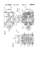
- FIG. 1 is a longitudinal vertical sectional view of the improved rotary actuator, but showing the servovalve in elevation.
- FIG. 2 is a horizontal sectional view thereof, this view taken generally on line 2--2 of FIG. 1 and looking in the direction of the arrows at the top of the body.
- FIG. 3 is a transverse vertical sectional view thereof, taken generally on line 3--3 of FIG. 1 and looking in the direction of the arrows.
- FIG. 4 is an exploded view of the actuator shown in FIG. 1, this view being provided for the principal purpose of identifying its structure without obfuscating the assembled view with a plethora of lead lines and reference numerals.
- FIG. 5 is a perspective view of a wrist actuator employing three of the improved rotary actuators and two brackets.
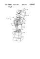
- FIG. 6 is a view of the wrist actuator shown in FIG. 5, but showing the wrist actuator as having been articulated to a "flattened" condition.
- the invention provides, in one aspect, an improved rotary actuator, of which the presently preferred embodiment is generally indicated at 10.
- Rotary actuator 10 is shown as broadly including an assembled body, collectively indicated at 11, a shaft 12 rotatably mounted on the body, a servovalve 13, and a vane-type motor 14 (FIG. 3) operatively arranged to urge the shaft to rotate relative to the body.
- Applicant's improvement centers around the provision of communicating supply passages 15, 16 in the body and shaft, respectively, so that supply pressure provided to a body supply passage inlet port 18 from some external source (not shown) is provided to the valve, and is also made available at the distal end of the shaft, for a purpose hereinafter discussed.
- these supply passages are accompanied by communicating body and shaft return passages 19, 20 which are available to convey a flow of return fluid from the valve and/or the distal end of the shaft to a body return passage outlet port 21.
- the body is formed by suitably assembling a left section 22, and intermediate section 23, and a right section 24.
- Body left section 22 is shown as including, inter alia, a planar vertical right face 25, from which a large diameter annular recess extends leftwardly into the left section to accommodate an O-Ring 26; an opposite annular vertical left face 28, from which a circular recess extends rightwardly into the left section to accommodate an O-Ring 29; and a specially-configured through-bore communicating the end faces and including, in pertinent part (from left to right in FIG. 4), an internally-threaded portion 30 extending rightwardly from left face 28, an inwardly-extending annular boss 31, a leftwardly-facing annular vertical shoulder 32, and a cylindrical surface 33 continuing rightwardly therefrom to join right face 25.
- a bearing assembly 34 is mounted on the left section with its right face arranged adjacent shoulder 32, and has its outer race 35 engaging the inwardly-facing cylindrical surface of boss 31.
- the bearing's inner race 36 engages a proximate portion of shaft 12.
- An annular left end cap 38 is mounted on the left section.
- End cap 38 has an annular vertical right face 39 engaging the left face of bearing assembly 34, has an externally-threaded portion 40 extending leftwardly therefrom and adapted to engage left section internally-threaded portion 30, and has a rightwardly-facing annular vertical surface 41 arranged to compressively engage O-Ring 29 and abut section left face 28.
- An annular corner recess extends into the end cap from its inwardly-facing cylindrical surface 42 and its right face 39 to accommodate a resilient annular seal 43, having a somewhat C-shaped cross-section. The inwardly-facing cylindrical surface of seal 43 wipingly engages a proximate portion of shaft 12.
- the body intermediate section 23 is shown as having a planar vertical left face 44 arranged to compress O-Ring 26 and abut left section right face 25, a planar vertical right face 45, and an uppermost planar horizontal surface 46, against which the servovalve is mounted.
- the intermediate section is also provided with a specially-configured through-bore having a somewhat C-shaped appearance when viewed in transverse cross-section (FIG. 3). Specifically, this through-bore is bounded by a relatively-large diameter cylindrical surface segment 48 occupying an arc of about 280 degrees, a smaller diameter cylindrical surface 49 occupying an arc of about 60 degrees, and planar surfaces 50, 51 symmetrically joining these surfaces.
- the intermediate section is further provides with a plurality of drilled holes which form parts of the body supply and return passages.
- a horizontal hole 52 extends through the intermediate section above its through-bore, and is intersected by a hole 53 extending downwardly from section upper surface 46. Holes 52 and 53 constitute a part of the body return passage 19.
- body hole 52 may communicate with an aligned hole 54 in the left body section to relieve pressure in the vicinity of the bearing.
- a horizontal hole 55 extends leftwardly into the intermediate section from its right face, and is intersected by a hole 56 extending downwardly from upper surface 46. Holes 55 and 56 constitute part of the body supply passage 15.
- the right body section 24 has a planar vertical left face 58, from which a relatively large diameter annular recess extends rightwardly into the section to accommodate an O-Ring 59; an opposite planar vertical right face 60, and planar horizontal upper and lower surfaces 61, 62, respectively.
- the right face 45 of the intermediate section is arranged to compressively engage O-Ring 59 and abut the left face 58 of the right section.
- the right section is also provided with a through-bore bounded by an inwardly-facing cylindrical surface 63, and has an annular recess extending outwardly into the section to accommodate an annular resilient seal 64, the inwardly-facing cylindrical surface of which wipingly engaged a proximate portion of shaft 12.
- the right section is provided with a plurality of holes and recesses which form other portions of the body supply and return passages 15, 19.
- a horizontal hole 65 extends into the section from inlet port 18, and is intersected by a hole 66 extending upwardly from lower surface 62 to intersect an annular recess 68 encircling the bore, and continuing therebeyond.
- a horizontal hole 69 aligned with intermediate section hole 55, extends into the right section from its left face to intersect the extension hole 66. Hole 66 is tapped between body lower surface 62 and hole 65 to receive a suitable closure plug 70.
- a horizontal hole 71 extends leftwardly into the right section from outlet port 21, and is intersected by a hole 72 extending downwardly from body upper surface 61 to intersect an annular recess 73 surrounding the bore at a location spaced axially from recess 68.
- Hole 72 is tapped between body upper surface 61 and hole 71 to receive a closure plug 74.
- a horizontal hole 75 aligned with intermediate section hole 52, extends into the right section from its left face 58 to intersect hole 72.
- the three body sections are assembled together, as shown in FIG. 1, and are held in this position by means of four bolts, severally indicated at 76 (FIGS. 2-3).
- the assembled body is thus provided with a supply passage 15, which includes inlet port 18, holes 65 and 66, annular recess 68, and the extension of hole 66, and holes 69, 55 and 56.
- the body return passage 19 includes outlet port 21, holes 71 and 72, recess 73, and holes 75, 52, 53 (and hole 54, if provided). Holes 56 and 53 open onto the intermediate section upper surface 46 to form ports aligned with the supply and return ports (not shown), respectively, of servovalve 13.
- the body supply passage 15 is arranged to convey supply pressure provided to inlet port 18 from an external source (not shown) to one location on the shaft, and to the supply port of valve 13.
- the body return passage 19 is arranged to convey fluid from the valve's return port, the chamber housing bearing 34 (if hole 54 is provided), and from another location on the shaft, to outlet port 21.
- the shaft is a horizontally-elongated member having a stepped outer surface, and is operatively arranged in the body bore.
- Shaft 12 has an annular vertical left end face 78 arranged without or outside the body; an annular vertical right end face 79; and an outer surface including (from left to right in FIG. 4) a cylindrical surface 80 extending rightwardly from left face 78, an annular recess 81, an annular boss having a leftwardly-facing annular vertical shoulder 82, an annular notch 83, a leftwardly-facing annular vertical shoulder 84 rotatably engaging the left section right face 25, a cylindrical surface 85 rotatably embraced by intermediate section arcuate surface 49 (FIG. 3), a rightwardly-facing annular vertical shoulder 86 rotatably engaging the right section left face 58, an annular notch 88, and a cylindrical surface 89 continuing rightwardly therefrom to join right face 79.
- the shaft is shown provided with supply and return passages 16, 20.
- the shaft supply passage 16 includes a horizontal hole 90 extending into the shaft from its left end face 78. The left marginal end portion of hole 90 may be tapped to receive a closure plug 91.
- Hole 90 is intersected within the body by a radial hole 92 in registry with annular recess 68, and without the body by a radial hole 93 adjacent left end face 78.
- the shaft return passage 20 includes a horizontal hole 94 extending rightwardly into the shaft from its left end face 78. The left marginal end portion of hole 94 is tapped to receive closure plug 95.
- Hole 94 is intersected within the body by a hole 96 in registry with annular recess 73, and without the body by a hole 98 arranged adjacent left end face 78.
- the shaft supply passage 16 has an inlet port communicating with the body supply passage outlet port, and is arranged to convey fluid to a location (i.e., hole 93) on the shaft beyond the body.
- shaft 12 Adjacent its left end, shaft 12 is provided with a tapped hole 99 to accommodate a set screw (not shown) by which some additional structure (not shown in FIGS. 1-4) may be coupled to the shaft for rotation therewith.
- a rotary position transducer is mounted on the body right section and engages the shaft via splined connection 101. This transducer is arranged to sense the angular position of the shaft relative to the body and to provide an electrical feedback signal reflective of such relative position.
- a rotary actuator having a shaft rotatably mounted on the body and a motor operative to urge the shaft to rotate relative to the body, a servovalve arranged to control fluid power to the motor, and a feedback transducer to sense angular position of the shaft relative to the body, constitute a rotary servoactuator.
- Valve 13 is preferably an electrohydraulic servovalve which has a supply port (not shown) communicating with hole 56, and has a return port (not shown) communicating with hole 53. Valve 13 also has two control ports C 1 and C 2 , which communicate with the intermediate section bore through holes 102, 103 respectively (FIGS. 2-3). Since valve 13 is individually “old” in this art, it will not be explicitly described. Suffice it to say here that valve 13 is supplied with pressurized fluid via the body and shaft supply passages, communicates with return via the body and shaft return passages, and is selectively operable in response to an electrical command signal to produce differential fluid control of either polarity between ports C 1 and C 2 .
- a vane 104 extends radially beyond shaft surface 85 and sealingly engages body surface 48.
- the vane thus divides the intermediate section bore into a first chamber 105 arranged to be supplied with control pressure from valve port C 1 via hole 102, and a second chamber 106 supplied with control pressure from valve port C 2 via hole 102.
- the differential between control pressure C 1 and C 2 acting on the opposing faces of the vane, selectively urges the shaft to rotate in either angular direction relative to the body, according to the polarity of the differential.
- the labyrinth of communicating supply passages function to connect body inlet port 18 to the valve supply port (not shown) and to a commutating port consisting of annular cavity 68 and shaft hole 92, thence to shaft outlet port 93.
- the commutating port serves to maintain the supply pressure connection to the shaft outlet port throughout the range of shaft rotational displacement.
- the communicating return passage connects body return port 98 to the valve return port (not shown) and to the shaft return inlet port 98 by way of commutating ports 73, 96.
- fluid power available between body supply and return ports 18, 21, will be always provided to the servovalve and to the distal end of the shaft beyond the body, independently of the angular position of the shaft relative to the body.
- This latter feature is deemed particularly advantageous because the fluid supply is made available for use in powering some other mechanism (not shown in FIGS. 1-4) which may be attached to the end of the shaft.
- the supply and return passages are provided within the body and shaft, and obviate the need for external flexible hoses.
- rotary actuator 10 contemplates that many possible changes and modifications may be made to rotary actuator 10, it being understood that the illustrated embodiment, while presently preferred, is illustrative and only one possible example of what the claims are intended to cover.
- the body need not invariable be of a three-piece sectional construction, nor need the various parts always have the same shape or function as in the preferred embodiment.
- the valve be an electrohydraulic servovalve, other types of valves may be necessarily mounted directly on the body, and the shaft may have different shapes.
- the commutating ports between the body and the shaft may take various forms, such as annular cavities formed on the shaft communicating with holes formed in the body, or similar cavities and/or holes formed at the end surface of the shaft which would communicate across an interface surface provided between the shaft and the body.
- the method of construction or assembly is not deemed critical and may be readily changed.
- the various holes may be cast or otherwise formed, instead of drilled.
- Other types of motors and/or mechanisms may be substituted for the single vane-type motor of the preferred embodiment.
- the improved actuator may be serviced by a variety of pressurized fluids (i.e., liquids or gases). In some applications, it may not be necessary to provide the return passages, such as when the valve or other fluid-powered mechanism is vented directly.
- the salient feature of the invention is to provide an improved rotary actuator in which pressurized fluid provided to the body is conveyed to the valve, and also through the shaft and beyond the body for availability in powering a suitable device or mechanism mounted on the shaft.
- the improved rotary actuator 10 heretofore described may be advantageously employed in an improved wrist actuator, generally indicated at 110 in FIGS. 5 and 6.
- Wrist actuator 110 is shown as including a lowermost first rotary actuator 10A, an intermediate second rotary actuator 10B, and an uppermost third rotary actuator 10C.
- the output shaft 12A (FIG. 6) of the first actuator is arranged vertically in FIG. 5.
- a base 111 of a somewhat U-shaped first bracket, generally indicated at 112 is mounted fast to the first actuator's output shaft, with its left and right arms 113, 114 embracing the body of second actuator 10B.
- the base 115 (FIG. 6) of another somewhat U-shaped second bracket, generally indicated at 116, is mounted on the body of the third actuator 10C, and has its right arm 117 mounted fast to the second actuators output shaft 12B.
- the left arm 118 of second bracket has its distal marginal end portion journalled in a bearing 119 provided on the body of the second actuator 10B.
- the first actuator 10A may be mounted on a suitable object (not shown), such as the end of a movable robot arm. As best shown in FIG. 6, selective operation of first actuator 10A causes the first bracket member 112 to pivot about the axis of the first actuator's shaft.
- the third actuator 10C may be selectively operated to cause desired rotation of its shaft.
- the third actuator's output shaft 12C is adapted to have mounted fast thereon, a suitable tool (not shown) or workpiece (not shown).
- the first and second actuators 10A, 10B function to position the third actuator's output shaft relative to an object.
- wrist actuator 110 One unique feature of wrist actuator 110 is the manner by which the supply and return ports of the three servovalves are connected hydraulically in parallel, so as to obviate the need for external hoses which might otherwise interfere with or by unduly fatigued by articulation of the wrist actuator.
- the supply and return passages communicate the body inlet and return ports (18, 21 in FIGS. 1-4) with the shaft outlet and inlet ports (93, 98 in FIGS. 1-4), respectively.
- the fluid power supply between the body ports is available at the end of each shaft.
- the first bracket 112 is mounted fast to the first shaft 12A by means of a set screw 120 received in shaft hole 99; and the second bracket is mounted fast to the second actuator output shaft by means of a like set screw.
- the first bracket includes a pair of horizontal supply and return passageways 121, 122, respectively, which extend rightwardly into the base 111 to communicate with the shaft's supply and return ports 93, 98, respectively.
- the left marginal end of these first bracket base passageways 121, 122 are closed by suitable plugs 123, 123.
- a pair of supply and return passages 124, 125 extend downwardly within the first bracket left arm 113 to intersect the base supply and return passages. The ends of these passageways may be closed by suitable closure plugs, again severally indicated at 123.
- These arm passageways 124, 125 communicate with the supply and return ports 18B, 21B of the second rotary actuator.
- the second bracket 116 has internal supply and return passages 126, 128 in its base 115 and arm 117, which communicate the second rotary actuator shaft supply and return ports 93B, 98B with the third rotary actuator body supply and return ports 18C, 21C, respectively.
- the supply and return ports of the three servovalves are connected hydraulically in parallel, by a labyrinth of communicating internal passageways.
- Supply pressure provided to the body supply port 18A of the first rotary actuator is provided through the first bracket to the body supply port 18B of the second rotary actuator, and is further provided through the second bracket to the body supply port 18C of the third rotary actuator.
- return fluid from the third actuator's return port 21C is provided through the second bracket to the second actuator's return port 21B, and is further provided through the first bracket to the first actuator's return port 21A.
- Each servovalve may be operated independently of one another to articulate the wrist actuator to the extent desired.
- each rotary actuator of the three-axis wrist assembly of FIG. 5 can be equipped with a rotary position transducer as indicated at 100A, B, C so that wrist motion is accomplished by multi-axis, rotary position servoactuators.
Abstract
Description
Claims (22)
Priority Applications (1)
| Application Number | Priority Date | Filing Date | Title |
|---|---|---|---|
| US06/638,564 US4899637A (en) | 1982-04-12 | 1984-09-17 | Oscilatory hydraulic actuators with internal supply, return, and control passageways for multi-axis wrist actuator |
Applications Claiming Priority (2)
| Application Number | Priority Date | Filing Date | Title |
|---|---|---|---|
| US36762582A | 1982-04-12 | 1982-04-12 | |
| US06/638,564 US4899637A (en) | 1982-04-12 | 1984-09-17 | Oscilatory hydraulic actuators with internal supply, return, and control passageways for multi-axis wrist actuator |
Related Parent Applications (1)
| Application Number | Title | Priority Date | Filing Date |
|---|---|---|---|
| US36762582A Continuation | 1982-04-12 | 1982-04-12 |
Publications (1)
| Publication Number | Publication Date |
|---|---|
| US4899637A true US4899637A (en) | 1990-02-13 |
Family
ID=27003864
Family Applications (1)
| Application Number | Title | Priority Date | Filing Date |
|---|---|---|---|
| US06/638,564 Expired - Fee Related US4899637A (en) | 1982-04-12 | 1984-09-17 | Oscilatory hydraulic actuators with internal supply, return, and control passageways for multi-axis wrist actuator |
Country Status (1)
| Country | Link |
|---|---|
| US (1) | US4899637A (en) |
Cited By (13)
| Publication number | Priority date | Publication date | Assignee | Title |
|---|---|---|---|---|
| US5241896A (en) * | 1992-05-27 | 1993-09-07 | Phd, Inc. | Pneumatic cylinder apparatus |
| US5261316A (en) * | 1987-12-30 | 1993-11-16 | Honda Giken Kogyo Kabushiki Kaisha | Angular displacement motor with counterbalance chambers |
| US6085782A (en) * | 1998-05-07 | 2000-07-11 | Gat Gesellschaft Fur Antriebstechnik Mbh | Device for fluid transfer |
| US6198247B1 (en) * | 1999-04-20 | 2001-03-06 | Steven Barr | Servo-articulated modules and robotic assemblies incorporating them |
| US20050139270A1 (en) * | 2003-12-24 | 2005-06-30 | Abb Process Industrie | Fluid delivery device |
| US20100126307A1 (en) * | 2008-09-29 | 2010-05-27 | Byoung Hoo Rho | Multi-turn hydraulic actuator |
| US20130004265A1 (en) * | 2009-10-21 | 2013-01-03 | Niels Henrik Bagge | Adjustment Head for a Hoisting Device |
| US20160288321A1 (en) * | 2015-04-02 | 2016-10-06 | Fanuc Corporation | Joint structure for robot including motor for causing arm to be swung |
| CN106217405A (en) * | 2016-08-26 | 2016-12-14 | 苏州元谋智能机器人系统有限公司 | A kind of robot modularized series connection joint that cooperates |
| US20180297216A1 (en) * | 2015-10-22 | 2018-10-18 | Thk Co., Ltd. | Universal coupling and robot joint structure |
| DE102020214332A1 (en) | 2020-11-13 | 2022-05-19 | Kuka Deutschland Gmbh | Robotic arm and method of assembling a robotic arm |
| US20220205465A1 (en) * | 2016-08-05 | 2022-06-30 | Woodward, Inc. | Multi-axis rotary piston actuator |
| US11389952B2 (en) * | 2018-07-27 | 2022-07-19 | Seiko Epson Corporation | Robot arm |
Citations (22)
| Publication number | Priority date | Publication date | Assignee | Title |
|---|---|---|---|---|
| GB514551A (en) * | 1935-11-09 | 1939-11-09 | Bristol Aeroplane Co Ltd | Improvements in or relating to apparatus for controlling the movements of a gun |
| US2442530A (en) * | 1946-03-18 | 1948-06-01 | Frank V Eberle | Hydraulically operated artificial body member |
| US2528464A (en) * | 1947-04-04 | 1950-10-31 | Ibm | Hydraulic artificial arm |
| US2605474A (en) * | 1947-11-22 | 1952-08-05 | Adel Prec Products Corp | Hydraulically controlled artificial leg |
| US2629876A (en) * | 1948-03-04 | 1953-03-03 | Robert S Fullerton | Hydraulic control system for artificial limbs |
| US2861701A (en) * | 1958-05-19 | 1958-11-25 | Gen Mills Inc | Remote controlled handling unit |
| US3289544A (en) * | 1964-03-04 | 1966-12-06 | Daniels Dennis | Rotary actuator |
| US3454169A (en) * | 1967-07-20 | 1969-07-08 | Robert H Bridges | Remote control submersible and/or remote manipulator arm |
| US3543910A (en) * | 1968-07-30 | 1970-12-01 | George C Devol | Work-head automatic motions controls |
| GB1256798A (en) * | 1968-03-29 | 1971-12-15 | ||
| US3683747A (en) * | 1970-02-09 | 1972-08-15 | Sperry Rand Corp | Manipulator and manipulator control system |
| US3739923A (en) * | 1970-02-20 | 1973-06-19 | Tokyo Shibaura Electric Co | Manipulator |
| US3954188A (en) * | 1973-12-26 | 1976-05-04 | Prab Conveyors, Inc. | Universal transfer device |
| US3975989A (en) * | 1973-04-19 | 1976-08-24 | Rudolf Felix Homberger | Pressure responsive force transmission apparatus |
| US3984009A (en) * | 1975-12-24 | 1976-10-05 | General Motors Corporation | Article gripper mounting device |
| US4062455A (en) * | 1976-11-22 | 1977-12-13 | Flatau Carl R | Remote manipulator |
| US4096766A (en) * | 1975-06-13 | 1978-06-27 | Sofermo | Self-contained modular joint, notably for robots |
| DE2815298A1 (en) * | 1978-03-31 | 1979-10-18 | Basfer Srl | IMPROVEMENT OF AUTOMATIC MACHINERY IN ROTATING POLE CONSTRUCTION, WITH ROTATING FLUIDODYNAMIC ACTUATORS |
| DE3022162A1 (en) * | 1980-06-13 | 1981-12-24 | Elac Ingenieurtechnik GmbH, 2300 Kiel | Rotary actuator with motion limiting for industrial robot - has actuator fluid supplied through swivel with limiting flow restrictor |
| US4351628A (en) * | 1979-04-11 | 1982-09-28 | Robert Bosch Gmbh | Article handling and transfer apparatus unit |
| US4372721A (en) * | 1981-05-18 | 1983-02-08 | Nordson Corporation | Apparatus for calibrating link position transducers of a teaching robot and a work robot |
| US4459898A (en) * | 1981-12-09 | 1984-07-17 | Nordson Corporation | Streamlined multi-axis robot wrist assembly with partially enclosed hydraulic and electrical lines to minimize the wrist envelope |
-
1984
- 1984-09-17 US US06/638,564 patent/US4899637A/en not_active Expired - Fee Related
Patent Citations (22)
| Publication number | Priority date | Publication date | Assignee | Title |
|---|---|---|---|---|
| GB514551A (en) * | 1935-11-09 | 1939-11-09 | Bristol Aeroplane Co Ltd | Improvements in or relating to apparatus for controlling the movements of a gun |
| US2442530A (en) * | 1946-03-18 | 1948-06-01 | Frank V Eberle | Hydraulically operated artificial body member |
| US2528464A (en) * | 1947-04-04 | 1950-10-31 | Ibm | Hydraulic artificial arm |
| US2605474A (en) * | 1947-11-22 | 1952-08-05 | Adel Prec Products Corp | Hydraulically controlled artificial leg |
| US2629876A (en) * | 1948-03-04 | 1953-03-03 | Robert S Fullerton | Hydraulic control system for artificial limbs |
| US2861701A (en) * | 1958-05-19 | 1958-11-25 | Gen Mills Inc | Remote controlled handling unit |
| US3289544A (en) * | 1964-03-04 | 1966-12-06 | Daniels Dennis | Rotary actuator |
| US3454169A (en) * | 1967-07-20 | 1969-07-08 | Robert H Bridges | Remote control submersible and/or remote manipulator arm |
| GB1256798A (en) * | 1968-03-29 | 1971-12-15 | ||
| US3543910A (en) * | 1968-07-30 | 1970-12-01 | George C Devol | Work-head automatic motions controls |
| US3683747A (en) * | 1970-02-09 | 1972-08-15 | Sperry Rand Corp | Manipulator and manipulator control system |
| US3739923A (en) * | 1970-02-20 | 1973-06-19 | Tokyo Shibaura Electric Co | Manipulator |
| US3975989A (en) * | 1973-04-19 | 1976-08-24 | Rudolf Felix Homberger | Pressure responsive force transmission apparatus |
| US3954188A (en) * | 1973-12-26 | 1976-05-04 | Prab Conveyors, Inc. | Universal transfer device |
| US4096766A (en) * | 1975-06-13 | 1978-06-27 | Sofermo | Self-contained modular joint, notably for robots |
| US3984009A (en) * | 1975-12-24 | 1976-10-05 | General Motors Corporation | Article gripper mounting device |
| US4062455A (en) * | 1976-11-22 | 1977-12-13 | Flatau Carl R | Remote manipulator |
| DE2815298A1 (en) * | 1978-03-31 | 1979-10-18 | Basfer Srl | IMPROVEMENT OF AUTOMATIC MACHINERY IN ROTATING POLE CONSTRUCTION, WITH ROTATING FLUIDODYNAMIC ACTUATORS |
| US4351628A (en) * | 1979-04-11 | 1982-09-28 | Robert Bosch Gmbh | Article handling and transfer apparatus unit |
| DE3022162A1 (en) * | 1980-06-13 | 1981-12-24 | Elac Ingenieurtechnik GmbH, 2300 Kiel | Rotary actuator with motion limiting for industrial robot - has actuator fluid supplied through swivel with limiting flow restrictor |
| US4372721A (en) * | 1981-05-18 | 1983-02-08 | Nordson Corporation | Apparatus for calibrating link position transducers of a teaching robot and a work robot |
| US4459898A (en) * | 1981-12-09 | 1984-07-17 | Nordson Corporation | Streamlined multi-axis robot wrist assembly with partially enclosed hydraulic and electrical lines to minimize the wrist envelope |
Non-Patent Citations (2)
| Title |
|---|
| Jacobs, E. "Minicomputer Controls Six Electrohydraulic Actuators," in Hydraulics and Pneumatics v. 35, 2: 53-8, Feb. 1982. |
| Jacobs, E. Minicomputer Controls Six Electrohydraulic Actuators, in Hydraulics and Pneumatics v. 35, 2: 53 8, Feb. 1982. * |
Cited By (18)
| Publication number | Priority date | Publication date | Assignee | Title |
|---|---|---|---|---|
| US5261316A (en) * | 1987-12-30 | 1993-11-16 | Honda Giken Kogyo Kabushiki Kaisha | Angular displacement motor with counterbalance chambers |
| US5241896A (en) * | 1992-05-27 | 1993-09-07 | Phd, Inc. | Pneumatic cylinder apparatus |
| US6085782A (en) * | 1998-05-07 | 2000-07-11 | Gat Gesellschaft Fur Antriebstechnik Mbh | Device for fluid transfer |
| US6198247B1 (en) * | 1999-04-20 | 2001-03-06 | Steven Barr | Servo-articulated modules and robotic assemblies incorporating them |
| US6459227B2 (en) * | 1999-04-20 | 2002-10-01 | Steven Barr | Servo-articulated modules and robotic assemblies incorporating them |
| US20050139270A1 (en) * | 2003-12-24 | 2005-06-30 | Abb Process Industrie | Fluid delivery device |
| US7013915B2 (en) * | 2003-12-24 | 2006-03-21 | Abb Process Industrie | Fluid delivery device |
| US8267374B2 (en) | 2008-09-29 | 2012-09-18 | Rpm Tech Co., Ltd. | Multi-turn hydraulic actuator |
| US20100126307A1 (en) * | 2008-09-29 | 2010-05-27 | Byoung Hoo Rho | Multi-turn hydraulic actuator |
| US20130004265A1 (en) * | 2009-10-21 | 2013-01-03 | Niels Henrik Bagge | Adjustment Head for a Hoisting Device |
| US9908763B2 (en) * | 2009-10-21 | 2018-03-06 | Hh Intellitech Aps | Adjustment head for a hoisting device |
| US20160288321A1 (en) * | 2015-04-02 | 2016-10-06 | Fanuc Corporation | Joint structure for robot including motor for causing arm to be swung |
| US9827682B2 (en) * | 2015-04-02 | 2017-11-28 | Fanuc Corporation | Joint structure for robot including motor for causing arm to be swung |
| US20180297216A1 (en) * | 2015-10-22 | 2018-10-18 | Thk Co., Ltd. | Universal coupling and robot joint structure |
| US20220205465A1 (en) * | 2016-08-05 | 2022-06-30 | Woodward, Inc. | Multi-axis rotary piston actuator |
| CN106217405A (en) * | 2016-08-26 | 2016-12-14 | 苏州元谋智能机器人系统有限公司 | A kind of robot modularized series connection joint that cooperates |
| US11389952B2 (en) * | 2018-07-27 | 2022-07-19 | Seiko Epson Corporation | Robot arm |
| DE102020214332A1 (en) | 2020-11-13 | 2022-05-19 | Kuka Deutschland Gmbh | Robotic arm and method of assembling a robotic arm |
Similar Documents
| Publication | Publication Date | Title |
|---|---|---|
| US4899637A (en) | Oscilatory hydraulic actuators with internal supply, return, and control passageways for multi-axis wrist actuator | |
| JP2673686B2 (en) | Joint | |
| CA1178311A (en) | Fluid power connector system for manipulator | |
| US5410944A (en) | Telescoping robot arm with spherical joints | |
| US4459898A (en) | Streamlined multi-axis robot wrist assembly with partially enclosed hydraulic and electrical lines to minimize the wrist envelope | |
| US5394766A (en) | Robotic human torso | |
| US20030029310A1 (en) | High pressure seal assembly for a hydraulic cylinder | |
| JPS5834208A (en) | Single stage servo valve | |
| GB2119855A (en) | Fluid-pressure rotary actuator | |
| US10718359B2 (en) | Devices and systems for producing rotational actuation | |
| US20150041689A1 (en) | Fluid-Actuated Butterfly Valve | |
| US5692412A (en) | Robotic manipulator | |
| JPS63245385A (en) | Wrist mechanism of robot manipulator | |
| US3918496A (en) | Three axes hydraulic remote control valve | |
| US5261316A (en) | Angular displacement motor with counterbalance chambers | |
| US4203351A (en) | Fluid motor actuator for rotating a shaft back and forth | |
| US11913562B2 (en) | Valve, and applications thereof in robot systems | |
| EP1343686B1 (en) | A hydraulic revolving actuator | |
| JPS646230Y2 (en) | ||
| AU2017331399B2 (en) | Subsea control valve | |
| JPS6144796Y2 (en) | ||
| JP2668254B2 (en) | Control device for piston in cylinder | |
| WO2020262700A1 (en) | Module robot | |
| JPS6065403U (en) | Servo motor hydraulic control device | |
| KR20050105971A (en) | Hydraulic device |
Legal Events
| Date | Code | Title | Description |
|---|---|---|---|
| AS | Assignment |
Owner name: MOOG CONTROLS INC., A CORP. OF DE., NEW YORK Free format text: ASSIGNMENT OF ASSIGNORS INTEREST.;ASSIGNOR:MOOG INC.;REEL/FRAME:005070/0175 Effective date: 19890502 |
|
| FEPP | Fee payment procedure |
Free format text: PAYOR NUMBER ASSIGNED (ORIGINAL EVENT CODE: ASPN); ENTITY STATUS OF PATENT OWNER: LARGE ENTITY |
|
| FPAY | Fee payment |
Year of fee payment: 4 |
|
| AS | Assignment |
Owner name: MARINE MIDLAND BANK, NEW YORK Free format text: SECURITY AGREEMENT;ASSIGNOR:MOOG INC.;REEL/FRAME:008200/0821 Effective date: 19961025 Owner name: MOOG INC., NEW YORK Free format text: CONFIRMATORY ASSIGNMENT;ASSIGNOR:MOOG CONTROLS, INC.;REEL/FRAME:008200/0817 Effective date: 19961026 |
|
| REMI | Maintenance fee reminder mailed | ||
| LAPS | Lapse for failure to pay maintenance fees | ||
| FP | Lapsed due to failure to pay maintenance fee |
Effective date: 19980218 |
|
| STCH | Information on status: patent discontinuation |
Free format text: PATENT EXPIRED DUE TO NONPAYMENT OF MAINTENANCE FEES UNDER 37 CFR 1.362 |