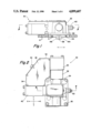
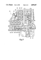
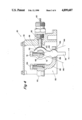
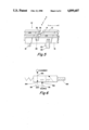
US4899607A - Electrically controlled pressurized fluid actuated X-Y shifting mechanism - Google Patents
Electrically controlled pressurized fluid actuated X-Y shifting mechanism Download PDFInfo
- Publication number
- US4899607A US4899607A US07/261,454 US26145488A US4899607A US 4899607 A US4899607 A US 4899607A US 26145488 A US26145488 A US 26145488A US 4899607 A US4899607 A US 4899607A
- Authority
- US
- United States
- Prior art keywords
- shift
- shaft
- housing
- shifting mechanism
- valves
- Prior art date
- Legal status (The legal status is an assumption and is not a legal conclusion. Google has not performed a legal analysis and makes no representation as to the accuracy of the status listed.)
- Expired - Fee Related
Links
Images
Classifications
-
- F—MECHANICAL ENGINEERING; LIGHTING; HEATING; WEAPONS; BLASTING
- F16—ENGINEERING ELEMENTS AND UNITS; GENERAL MEASURES FOR PRODUCING AND MAINTAINING EFFECTIVE FUNCTIONING OF MACHINES OR INSTALLATIONS; THERMAL INSULATION IN GENERAL
- F16H—GEARING
- F16H61/00—Control functions within control units of change-speed- or reversing-gearings for conveying rotary motion ; Control of exclusively fluid gearing, friction gearing, gearings with endless flexible members or other particular types of gearing
- F16H61/26—Generation or transmission of movements for final actuating mechanisms
- F16H61/28—Generation or transmission of movements for final actuating mechanisms with at least one movement of the final actuating mechanism being caused by a non-mechanical force, e.g. power-assisted
- F16H61/2807—Generation or transmission of movements for final actuating mechanisms with at least one movement of the final actuating mechanism being caused by a non-mechanical force, e.g. power-assisted using electric control signals for shift actuators, e.g. electro-hydraulic control therefor
-
- F—MECHANICAL ENGINEERING; LIGHTING; HEATING; WEAPONS; BLASTING
- F16—ENGINEERING ELEMENTS AND UNITS; GENERAL MEASURES FOR PRODUCING AND MAINTAINING EFFECTIVE FUNCTIONING OF MACHINES OR INSTALLATIONS; THERMAL INSULATION IN GENERAL
- F16H—GEARING
- F16H61/00—Control functions within control units of change-speed- or reversing-gearings for conveying rotary motion ; Control of exclusively fluid gearing, friction gearing, gearings with endless flexible members or other particular types of gearing
- F16H61/26—Generation or transmission of movements for final actuating mechanisms
- F16H61/28—Generation or transmission of movements for final actuating mechanisms with at least one movement of the final actuating mechanism being caused by a non-mechanical force, e.g. power-assisted
- F16H61/30—Hydraulic or pneumatic motors or related fluid control means therefor
- F16H2061/307—Actuators with three or more defined positions, e.g. three position servos
-
- F—MECHANICAL ENGINEERING; LIGHTING; HEATING; WEAPONS; BLASTING
- F16—ENGINEERING ELEMENTS AND UNITS; GENERAL MEASURES FOR PRODUCING AND MAINTAINING EFFECTIVE FUNCTIONING OF MACHINES OR INSTALLATIONS; THERMAL INSULATION IN GENERAL
- F16H—GEARING
- F16H61/00—Control functions within control units of change-speed- or reversing-gearings for conveying rotary motion ; Control of exclusively fluid gearing, friction gearing, gearings with endless flexible members or other particular types of gearing
- F16H61/26—Generation or transmission of movements for final actuating mechanisms
- F16H61/28—Generation or transmission of movements for final actuating mechanisms with at least one movement of the final actuating mechanism being caused by a non-mechanical force, e.g. power-assisted
- F16H61/30—Hydraulic or pneumatic motors or related fluid control means therefor
- F16H2061/308—Modular hydraulic shift units, i.e. preassembled actuator units for select and shift movements adapted for being mounted on transmission casing
-
- Y—GENERAL TAGGING OF NEW TECHNOLOGICAL DEVELOPMENTS; GENERAL TAGGING OF CROSS-SECTIONAL TECHNOLOGIES SPANNING OVER SEVERAL SECTIONS OF THE IPC; TECHNICAL SUBJECTS COVERED BY FORMER USPC CROSS-REFERENCE ART COLLECTIONS [XRACs] AND DIGESTS
- Y10—TECHNICAL SUBJECTS COVERED BY FORMER USPC
- Y10T—TECHNICAL SUBJECTS COVERED BY FORMER US CLASSIFICATION
- Y10T74/00—Machine element or mechanism
- Y10T74/19—Gearing
- Y10T74/19219—Interchangeably locked
- Y10T74/19251—Control mechanism
-
- Y—GENERAL TAGGING OF NEW TECHNOLOGICAL DEVELOPMENTS; GENERAL TAGGING OF CROSS-SECTIONAL TECHNOLOGIES SPANNING OVER SEVERAL SECTIONS OF THE IPC; TECHNICAL SUBJECTS COVERED BY FORMER USPC CROSS-REFERENCE ART COLLECTIONS [XRACs] AND DIGESTS
- Y10—TECHNICAL SUBJECTS COVERED BY FORMER USPC
- Y10T—TECHNICAL SUBJECTS COVERED BY FORMER US CLASSIFICATION
- Y10T74/00—Machine element or mechanism
- Y10T74/19—Gearing
- Y10T74/19219—Interchangeably locked
- Y10T74/19377—Slidable keys or clutches
- Y10T74/19414—Single clutch shaft
- Y10T74/19419—Progressive
- Y10T74/19423—Multiple key
- Y10T74/19428—Spur
- Y10T74/19433—Fluid operated
-
- Y—GENERAL TAGGING OF NEW TECHNOLOGICAL DEVELOPMENTS; GENERAL TAGGING OF CROSS-SECTIONAL TECHNOLOGIES SPANNING OVER SEVERAL SECTIONS OF THE IPC; TECHNICAL SUBJECTS COVERED BY FORMER USPC CROSS-REFERENCE ART COLLECTIONS [XRACs] AND DIGESTS
- Y10—TECHNICAL SUBJECTS COVERED BY FORMER USPC
- Y10T—TECHNICAL SUBJECTS COVERED BY FORMER US CLASSIFICATION
- Y10T74/00—Machine element or mechanism
- Y10T74/19—Gearing
- Y10T74/19219—Interchangeably locked
- Y10T74/19377—Slidable keys or clutches
- Y10T74/19414—Single clutch shaft
- Y10T74/19419—Progressive
- Y10T74/19423—Multiple key
- Y10T74/19428—Spur
- Y10T74/19437—Electrically operated
-
- Y—GENERAL TAGGING OF NEW TECHNOLOGICAL DEVELOPMENTS; GENERAL TAGGING OF CROSS-SECTIONAL TECHNOLOGIES SPANNING OVER SEVERAL SECTIONS OF THE IPC; TECHNICAL SUBJECTS COVERED BY FORMER USPC CROSS-REFERENCE ART COLLECTIONS [XRACs] AND DIGESTS
- Y10—TECHNICAL SUBJECTS COVERED BY FORMER USPC
- Y10T—TECHNICAL SUBJECTS COVERED BY FORMER US CLASSIFICATION
- Y10T74/00—Machine element or mechanism
- Y10T74/20—Control lever and linkage systems
- Y10T74/20012—Multiple controlled elements
- Y10T74/20018—Transmission control
- Y10T74/20024—Fluid actuator
-
- Y—GENERAL TAGGING OF NEW TECHNOLOGICAL DEVELOPMENTS; GENERAL TAGGING OF CROSS-SECTIONAL TECHNOLOGIES SPANNING OVER SEVERAL SECTIONS OF THE IPC; TECHNICAL SUBJECTS COVERED BY FORMER USPC CROSS-REFERENCE ART COLLECTIONS [XRACs] AND DIGESTS
- Y10—TECHNICAL SUBJECTS COVERED BY FORMER USPC
- Y10T—TECHNICAL SUBJECTS COVERED BY FORMER US CLASSIFICATION
- Y10T74/00—Machine element or mechanism
- Y10T74/20—Control lever and linkage systems
- Y10T74/20012—Multiple controlled elements
- Y10T74/20018—Transmission control
- Y10T74/2003—Electrical actuator
Abstract
Description
Claims (10)
Applications Claiming Priority (2)
| Application Number | Priority Date | Filing Date | Title |
|---|---|---|---|
| GB8725981 | 1987-11-05 | ||
| GB878725981A GB8725981D0 (en) | 1987-11-05 | 1987-11-05 | X-y shifting mechanism |
Publications (1)
| Publication Number | Publication Date |
|---|---|
| US4899607A true US4899607A (en) | 1990-02-13 |
Family
ID=10626512
Family Applications (1)
| Application Number | Title | Priority Date | Filing Date |
|---|---|---|---|
| US07/261,454 Expired - Fee Related US4899607A (en) | 1987-11-05 | 1988-10-24 | Electrically controlled pressurized fluid actuated X-Y shifting mechanism |
Country Status (8)
| Country | Link |
|---|---|
| US (1) | US4899607A (en) |
| EP (1) | EP0315347B1 (en) |
| JP (1) | JPH01153849A (en) |
| AU (1) | AU611362B2 (en) |
| BR (1) | BR8805679A (en) |
| DE (1) | DE3883917T2 (en) |
| ES (1) | ES2058307T3 (en) |
| GB (1) | GB8725981D0 (en) |
Cited By (56)
| Publication number | Priority date | Publication date | Assignee | Title |
|---|---|---|---|---|
| US5031472A (en) * | 1989-02-11 | 1991-07-16 | Eaton Corporation | Neutral sensing assembly |
| US5094126A (en) * | 1989-01-25 | 1992-03-10 | Eaton Corporation | Transmission with a detachable emergency ratio selector |
| US5099711A (en) * | 1991-05-09 | 1992-03-31 | Eaton Corporation | Tooth butt/buzz control method/system |
| US5109721A (en) * | 1991-05-09 | 1992-05-05 | Eaton Corporation | Range shifting only fault tolerance method/system |
| US5109729A (en) * | 1991-05-09 | 1992-05-05 | Eaton Corporation | Throttle control fault detection and tolerance method/system |
| US5121649A (en) * | 1990-03-30 | 1992-06-16 | Valeo | Motorized gear shift control apparatus for a transmission gearbox, in particular for automotive vehicles |
| US5136897A (en) * | 1991-05-09 | 1992-08-11 | Eaton Corporation | Smooth upshift control method/system |
| US5138905A (en) * | 1990-08-31 | 1992-08-18 | Isuzu Motors, Ltd. | Electronic-controlled transmission |
| US5191804A (en) * | 1992-07-23 | 1993-03-09 | Eaton Corporation | Dual force fluid actuated shift device |
| US5274553A (en) * | 1991-05-09 | 1993-12-28 | Eaton Corporation | Torque converter slip rate based skip power downshift control strategy |
| US5279172A (en) * | 1992-10-22 | 1994-01-18 | Eaton Corporation | Four position fluid-actuated piston arrangement |
| US5305213A (en) * | 1991-05-09 | 1994-04-19 | Eaton Corporation | Driveline torque limit control strategy-using SAE J1922 type engine control |
| US5305240A (en) * | 1992-11-25 | 1994-04-19 | Eaton Corporation | Computer controlled method of calibrating an x-y shifter |
| US5389053A (en) * | 1993-07-21 | 1995-02-14 | Eaton Corporation | System and method for sliding clutch engagement under tooth butt or torque lock conditions |
| US5408898A (en) * | 1993-11-10 | 1995-04-25 | Eaton Corporation | Preselect shift strategy using stored energy |
| US5413012A (en) * | 1993-09-07 | 1995-05-09 | Eaton Corporation | Variable synchronous window |
| US5417124A (en) * | 1991-11-08 | 1995-05-23 | Iveco Fiat S.P.A. | Gear change for an industrial vehicle provided with an integrated control unit |
| US5425284A (en) * | 1993-09-07 | 1995-06-20 | Eaton Corporation | Automated mechanical transmission control system/method |
| EP0688977A2 (en) | 1994-06-25 | 1995-12-27 | Eaton Corporation | Engagement fault degraded mode control for transmissions |
| EP0688978A2 (en) | 1994-06-25 | 1995-12-27 | Eaton Corporation | Splitter section engagement control |
| EP0695891A2 (en) | 1994-08-05 | 1996-02-07 | Eaton Corporation | Start ratio selection system and method |
| EP0695893A2 (en) | 1994-08-06 | 1996-02-07 | Eaton Corporation | Continuous selection control for semi-automatic mechanical transmission |
| EP0697302A2 (en) | 1994-08-19 | 1996-02-21 | Eaton Corporation | Downshift logic for semi-automatic mechanical transmission with manual clutch controller |
| EP0702170A2 (en) | 1994-09-19 | 1996-03-20 | Eaton Corporation | Clutch reengagement control |
| US5528949A (en) * | 1993-03-03 | 1996-06-25 | Eaton Corporation | Three-position shift actuator |
| US5566070A (en) * | 1995-02-02 | 1996-10-15 | Eaton Corporation | Transmission shift control including deflection-type neutral signal error detection and response |
| US5623852A (en) * | 1993-04-10 | 1997-04-29 | Hydraulik-Ring Antriebs- Und Steuerungstechnik Gmbh | Adjusting drive system for transmission of motorized vehicles |
| EP0778429A2 (en) | 1995-12-07 | 1997-06-11 | Eaton Corporation | Control for automated mechanical transmission system |
| EP0784171A2 (en) | 1996-01-12 | 1997-07-16 | Eaton Corporation | Automated transmission system with best gear selection on up- or downshift request |
| US5661998A (en) * | 1996-02-06 | 1997-09-02 | Eaton Corporation | Three-position actuator piston assembly and actuator system utilizing same |
| US5743143A (en) * | 1996-08-09 | 1998-04-28 | Eaton Corporation | Transmission shifting mechanism and position sensor |
| US5878622A (en) * | 1996-02-23 | 1999-03-09 | Hydraulik--Ring Antriebs- und Steuerungstechnik GmbH | Actuating device for automatically operating manual transmissions of vehicles |
| EP0911207A2 (en) | 1997-10-16 | 1999-04-28 | Eaton Corporation | Shift control system and method for optimal engine braking |
| US5941137A (en) * | 1995-08-11 | 1999-08-24 | Siemens Aktiengesellschaft | Controller for a motor vehicle with an automatic transmission |
| EP0947739A2 (en) | 1998-04-01 | 1999-10-06 | Eaton Corporation | Range shift control |
| EP0947740A2 (en) | 1998-04-01 | 1999-10-06 | Eaton Corporation | Dynamic range shift actuation |
| EP0947371A2 (en) | 1998-04-01 | 1999-10-06 | Eaton Corporation | Adaptive splitter actuator engagement force control |
| EP0947372A2 (en) | 1998-04-01 | 1999-10-06 | Eaton Corporation | Engine fuel control for completing shifts in controller-assisted, manually shifted transmission |
| EP0947741A2 (en) | 1998-04-01 | 1999-10-06 | Eaton Corporation | Adaptive upshift jaw clutch engagement control |
| EP0947744A2 (en) | 1998-04-01 | 1999-10-06 | Eaton Corporation | Jaw clutch engagement control for assisted, manually shifted, splitter type transmission system |
| EP0947737A2 (en) | 1998-04-01 | 1999-10-06 | Eaton Corporation | Adaptive neutral sensing |
| US6000294A (en) * | 1997-11-15 | 1999-12-14 | Eaton Corporation | System and method for fluid assisted shifting of mechanical transmissions |
| EP0997671A2 (en) | 1998-10-26 | 2000-05-03 | Eaton Corporation | Robust control for three-position transmission shift actuator assembly |
| US6131476A (en) * | 1998-04-01 | 2000-10-17 | Aisin Ai Co., Ltd. | Gear ratio selecting and shifting apparatus in a transmission |
| US6189396B1 (en) * | 1996-02-10 | 2001-02-20 | Audi Ag | Control arrangement for an automatic, electrohydraulically controlled transmission |
| US6301537B1 (en) | 2000-06-05 | 2001-10-09 | Eaton Corporation | Adaptive calibration of X-Y position sensor |
| US6658339B1 (en) | 1999-11-26 | 2003-12-02 | Eaton Corporation | Driver-programmable driving mode system for automatic transmissions |
| US20050155446A1 (en) * | 2002-01-25 | 2005-07-21 | Ian Heathcote | Gear shifting cassette system |
| US20080188349A1 (en) * | 2007-02-02 | 2008-08-07 | Mike Romine | PTO brake |
| CN101046250B (en) * | 2006-03-31 | 2010-05-12 | 上海盈达信汽车电子有限公司 | Electrically controlled and hydraulically driven automatic speed varying executor |
| DE112009000128T5 (en) | 2008-01-18 | 2010-12-23 | Eaton Corp., Cleveland | PTO overspeed protection strategy |
| CN103185135A (en) * | 2011-12-29 | 2013-07-03 | 广西玉柴机器股份有限公司 | Drive mechanism of automated electrically-controlled mechanical transmission |
| US20140165767A1 (en) * | 2012-12-19 | 2014-06-19 | Deere And Company | Manual synchronized gear shift assist |
| KR20190031361A (en) * | 2017-09-15 | 2019-03-26 | 명화공업주식회사 | Actuator piston assembly |
| KR20190031362A (en) * | 2017-09-15 | 2019-03-26 | 명화공업주식회사 | Fluid supply structure of an actuator piston assembly |
| KR20190031363A (en) * | 2017-09-15 | 2019-03-26 | 명화공업주식회사 | Stopper structure of an actuator piston assembly |
Families Citing this family (6)
| Publication number | Priority date | Publication date | Assignee | Title |
|---|---|---|---|---|
| GB8829074D0 (en) * | 1988-12-13 | 1989-01-25 | Eaton Gmbh | Shifting system for change speed transmission |
| US4928544A (en) * | 1989-06-19 | 1990-05-29 | Eaton Corporation | Dual pressure pressurized fluid actuated shifting mechanism |
| GB9006091D0 (en) * | 1990-03-17 | 1990-05-16 | Eaton Corp | Transducer fault test logic |
| DE19539472A1 (en) * | 1995-10-24 | 1997-04-30 | Zahnradfabrik Friedrichshafen | Switching device for motor vehicle change gearbox - pneumatic shift servo - |
| DE19615267C1 (en) * | 1996-04-18 | 1997-06-12 | Getrag Getriebe Zahnrad | Automated manual gear-shift circuit arrangement for motor vehicle transmission |
| JP4903674B2 (en) * | 2007-11-20 | 2012-03-28 | 京浜精密工業株式会社 | Shifting operation mechanism |
Citations (14)
| Publication number | Priority date | Publication date | Assignee | Title |
|---|---|---|---|---|
| US2137953A (en) * | 1936-11-04 | 1938-11-22 | Bendix Westinghouse Automotive | Control mechanism |
| US2931237A (en) * | 1957-12-02 | 1960-04-05 | Fuller Mfg Co | Automotive device |
| US2951392A (en) * | 1957-11-01 | 1960-09-06 | Fuller Mfg Co | Automotive device |
| US3039321A (en) * | 1958-01-31 | 1962-06-19 | Weymann Charles Terres | Automatic drive |
| US3093008A (en) * | 1959-08-18 | 1963-06-11 | Huntly Engineering & Welding C | Remote control for auxiliary transmissions |
| US3433101A (en) * | 1966-01-27 | 1969-03-18 | Bosch Gmbh Robert | Electronic arrangement for shifting gears in motor vehicles |
| US3793898A (en) * | 1971-05-18 | 1974-02-26 | Bosch Gmbh Robert | Gear shifting assembly for change-speed transmissions |
| US4275612A (en) * | 1978-03-30 | 1981-06-30 | Eaton Corporation | Shift control for change speed gear transmission for vehicle |
| US4455883A (en) * | 1980-11-14 | 1984-06-26 | Eaton Corporation | Combined shift control |
| US4515029A (en) * | 1982-11-08 | 1985-05-07 | Eaton Corporation | Compound variable mechanical advantage shifting mechanism |
| US4567785A (en) * | 1983-12-16 | 1986-02-04 | Eaton Corporation | Directly mounted master shift control |
| US4580457A (en) * | 1983-06-29 | 1986-04-08 | Isuzu Motors, Ltd. | Manual or hydraulic gearshifting apparatus |
| US4584895A (en) * | 1984-06-11 | 1986-04-29 | Eaton Corporation | Transmission shift control |
| US4690008A (en) * | 1984-08-10 | 1987-09-01 | Wabco Westinghouse Fahrzeugbremsen Gmbh | Gearshift range preconditioning system |
Family Cites Families (4)
| Publication number | Priority date | Publication date | Assignee | Title |
|---|---|---|---|---|
| DE1113620B (en) * | 1958-07-16 | 1961-09-07 | Magneti Marelli Spa | Pre-selection and switching device for gear change transmission |
| FR1432945A (en) * | 1964-04-15 | 1966-03-25 | Turner Mfg Co Ltd | Clutch control mechanism, especially of automobile gearboxes |
| US4625840A (en) * | 1983-08-19 | 1986-12-02 | Diesel Kiki Co., Ltd. | Hydraulic control unit for automotive transmissions |
| FR2556291B1 (en) * | 1983-12-09 | 1988-10-28 | France Etat Armement | REMOTE CONTROL SYSTEM FOR A MECHANICAL GEARBOX |
-
1987
- 1987-11-05 GB GB878725981A patent/GB8725981D0/en active Pending
-
1988
- 1988-10-24 BR BR888805679A patent/BR8805679A/en not_active IP Right Cessation
- 1988-10-24 US US07/261,454 patent/US4899607A/en not_active Expired - Fee Related
- 1988-10-24 ES ES88309969T patent/ES2058307T3/en not_active Expired - Lifetime
- 1988-10-24 DE DE88309969T patent/DE3883917T2/en not_active Expired - Fee Related
- 1988-10-24 EP EP88309969A patent/EP0315347B1/en not_active Expired - Lifetime
- 1988-10-31 JP JP63275958A patent/JPH01153849A/en active Pending
- 1988-11-04 AU AU24689/88A patent/AU611362B2/en not_active Ceased
Patent Citations (14)
| Publication number | Priority date | Publication date | Assignee | Title |
|---|---|---|---|---|
| US2137953A (en) * | 1936-11-04 | 1938-11-22 | Bendix Westinghouse Automotive | Control mechanism |
| US2951392A (en) * | 1957-11-01 | 1960-09-06 | Fuller Mfg Co | Automotive device |
| US2931237A (en) * | 1957-12-02 | 1960-04-05 | Fuller Mfg Co | Automotive device |
| US3039321A (en) * | 1958-01-31 | 1962-06-19 | Weymann Charles Terres | Automatic drive |
| US3093008A (en) * | 1959-08-18 | 1963-06-11 | Huntly Engineering & Welding C | Remote control for auxiliary transmissions |
| US3433101A (en) * | 1966-01-27 | 1969-03-18 | Bosch Gmbh Robert | Electronic arrangement for shifting gears in motor vehicles |
| US3793898A (en) * | 1971-05-18 | 1974-02-26 | Bosch Gmbh Robert | Gear shifting assembly for change-speed transmissions |
| US4275612A (en) * | 1978-03-30 | 1981-06-30 | Eaton Corporation | Shift control for change speed gear transmission for vehicle |
| US4455883A (en) * | 1980-11-14 | 1984-06-26 | Eaton Corporation | Combined shift control |
| US4515029A (en) * | 1982-11-08 | 1985-05-07 | Eaton Corporation | Compound variable mechanical advantage shifting mechanism |
| US4580457A (en) * | 1983-06-29 | 1986-04-08 | Isuzu Motors, Ltd. | Manual or hydraulic gearshifting apparatus |
| US4567785A (en) * | 1983-12-16 | 1986-02-04 | Eaton Corporation | Directly mounted master shift control |
| US4584895A (en) * | 1984-06-11 | 1986-04-29 | Eaton Corporation | Transmission shift control |
| US4690008A (en) * | 1984-08-10 | 1987-09-01 | Wabco Westinghouse Fahrzeugbremsen Gmbh | Gearshift range preconditioning system |
Cited By (59)
| Publication number | Priority date | Publication date | Assignee | Title |
|---|---|---|---|---|
| US5094126A (en) * | 1989-01-25 | 1992-03-10 | Eaton Corporation | Transmission with a detachable emergency ratio selector |
| US5031472A (en) * | 1989-02-11 | 1991-07-16 | Eaton Corporation | Neutral sensing assembly |
| US5121649A (en) * | 1990-03-30 | 1992-06-16 | Valeo | Motorized gear shift control apparatus for a transmission gearbox, in particular for automotive vehicles |
| US5138905A (en) * | 1990-08-31 | 1992-08-18 | Isuzu Motors, Ltd. | Electronic-controlled transmission |
| US5305213A (en) * | 1991-05-09 | 1994-04-19 | Eaton Corporation | Driveline torque limit control strategy-using SAE J1922 type engine control |
| US5099711A (en) * | 1991-05-09 | 1992-03-31 | Eaton Corporation | Tooth butt/buzz control method/system |
| US5109721A (en) * | 1991-05-09 | 1992-05-05 | Eaton Corporation | Range shifting only fault tolerance method/system |
| US5109729A (en) * | 1991-05-09 | 1992-05-05 | Eaton Corporation | Throttle control fault detection and tolerance method/system |
| US5136897A (en) * | 1991-05-09 | 1992-08-11 | Eaton Corporation | Smooth upshift control method/system |
| US5274553A (en) * | 1991-05-09 | 1993-12-28 | Eaton Corporation | Torque converter slip rate based skip power downshift control strategy |
| US5417124A (en) * | 1991-11-08 | 1995-05-23 | Iveco Fiat S.P.A. | Gear change for an industrial vehicle provided with an integrated control unit |
| US5191804A (en) * | 1992-07-23 | 1993-03-09 | Eaton Corporation | Dual force fluid actuated shift device |
| US5279172A (en) * | 1992-10-22 | 1994-01-18 | Eaton Corporation | Four position fluid-actuated piston arrangement |
| US5305240A (en) * | 1992-11-25 | 1994-04-19 | Eaton Corporation | Computer controlled method of calibrating an x-y shifter |
| US5528949A (en) * | 1993-03-03 | 1996-06-25 | Eaton Corporation | Three-position shift actuator |
| US5623852A (en) * | 1993-04-10 | 1997-04-29 | Hydraulik-Ring Antriebs- Und Steuerungstechnik Gmbh | Adjusting drive system for transmission of motorized vehicles |
| US5389053A (en) * | 1993-07-21 | 1995-02-14 | Eaton Corporation | System and method for sliding clutch engagement under tooth butt or torque lock conditions |
| US5413012A (en) * | 1993-09-07 | 1995-05-09 | Eaton Corporation | Variable synchronous window |
| US5425284A (en) * | 1993-09-07 | 1995-06-20 | Eaton Corporation | Automated mechanical transmission control system/method |
| US5408898A (en) * | 1993-11-10 | 1995-04-25 | Eaton Corporation | Preselect shift strategy using stored energy |
| EP0688978A2 (en) | 1994-06-25 | 1995-12-27 | Eaton Corporation | Splitter section engagement control |
| EP0688977A2 (en) | 1994-06-25 | 1995-12-27 | Eaton Corporation | Engagement fault degraded mode control for transmissions |
| EP0695891A2 (en) | 1994-08-05 | 1996-02-07 | Eaton Corporation | Start ratio selection system and method |
| EP0695893A2 (en) | 1994-08-06 | 1996-02-07 | Eaton Corporation | Continuous selection control for semi-automatic mechanical transmission |
| EP0697302A2 (en) | 1994-08-19 | 1996-02-21 | Eaton Corporation | Downshift logic for semi-automatic mechanical transmission with manual clutch controller |
| EP0702170A2 (en) | 1994-09-19 | 1996-03-20 | Eaton Corporation | Clutch reengagement control |
| US5566070A (en) * | 1995-02-02 | 1996-10-15 | Eaton Corporation | Transmission shift control including deflection-type neutral signal error detection and response |
| US5941137A (en) * | 1995-08-11 | 1999-08-24 | Siemens Aktiengesellschaft | Controller for a motor vehicle with an automatic transmission |
| EP0778429A2 (en) | 1995-12-07 | 1997-06-11 | Eaton Corporation | Control for automated mechanical transmission system |
| EP0784171A2 (en) | 1996-01-12 | 1997-07-16 | Eaton Corporation | Automated transmission system with best gear selection on up- or downshift request |
| US5661998A (en) * | 1996-02-06 | 1997-09-02 | Eaton Corporation | Three-position actuator piston assembly and actuator system utilizing same |
| US6189396B1 (en) * | 1996-02-10 | 2001-02-20 | Audi Ag | Control arrangement for an automatic, electrohydraulically controlled transmission |
| US5878622A (en) * | 1996-02-23 | 1999-03-09 | Hydraulik--Ring Antriebs- und Steuerungstechnik GmbH | Actuating device for automatically operating manual transmissions of vehicles |
| US5743143A (en) * | 1996-08-09 | 1998-04-28 | Eaton Corporation | Transmission shifting mechanism and position sensor |
| EP0911207A2 (en) | 1997-10-16 | 1999-04-28 | Eaton Corporation | Shift control system and method for optimal engine braking |
| US6000294A (en) * | 1997-11-15 | 1999-12-14 | Eaton Corporation | System and method for fluid assisted shifting of mechanical transmissions |
| EP0947372A2 (en) | 1998-04-01 | 1999-10-06 | Eaton Corporation | Engine fuel control for completing shifts in controller-assisted, manually shifted transmission |
| EP0947371A2 (en) | 1998-04-01 | 1999-10-06 | Eaton Corporation | Adaptive splitter actuator engagement force control |
| EP0947741A2 (en) | 1998-04-01 | 1999-10-06 | Eaton Corporation | Adaptive upshift jaw clutch engagement control |
| EP0947744A2 (en) | 1998-04-01 | 1999-10-06 | Eaton Corporation | Jaw clutch engagement control for assisted, manually shifted, splitter type transmission system |
| EP0947737A2 (en) | 1998-04-01 | 1999-10-06 | Eaton Corporation | Adaptive neutral sensing |
| EP0947740A2 (en) | 1998-04-01 | 1999-10-06 | Eaton Corporation | Dynamic range shift actuation |
| US6131476A (en) * | 1998-04-01 | 2000-10-17 | Aisin Ai Co., Ltd. | Gear ratio selecting and shifting apparatus in a transmission |
| EP0947739A2 (en) | 1998-04-01 | 1999-10-06 | Eaton Corporation | Range shift control |
| EP0997671A2 (en) | 1998-10-26 | 2000-05-03 | Eaton Corporation | Robust control for three-position transmission shift actuator assembly |
| US6658339B1 (en) | 1999-11-26 | 2003-12-02 | Eaton Corporation | Driver-programmable driving mode system for automatic transmissions |
| US6301537B1 (en) | 2000-06-05 | 2001-10-09 | Eaton Corporation | Adaptive calibration of X-Y position sensor |
| US20050155446A1 (en) * | 2002-01-25 | 2005-07-21 | Ian Heathcote | Gear shifting cassette system |
| CN101046250B (en) * | 2006-03-31 | 2010-05-12 | 上海盈达信汽车电子有限公司 | Electrically controlled and hydraulically driven automatic speed varying executor |
| US20080188349A1 (en) * | 2007-02-02 | 2008-08-07 | Mike Romine | PTO brake |
| US7905812B2 (en) | 2007-02-02 | 2011-03-15 | Eaton Corporation | PTO brake |
| DE112009000128T5 (en) | 2008-01-18 | 2010-12-23 | Eaton Corp., Cleveland | PTO overspeed protection strategy |
| US8046140B2 (en) | 2008-01-18 | 2011-10-25 | Eaton Corporation | PTO overspeed protection strategy |
| CN103185135A (en) * | 2011-12-29 | 2013-07-03 | 广西玉柴机器股份有限公司 | Drive mechanism of automated electrically-controlled mechanical transmission |
| CN103185135B (en) * | 2011-12-29 | 2015-04-29 | 广西玉柴机器股份有限公司 | Drive mechanism of automated electrically-controlled mechanical transmission |
| US20140165767A1 (en) * | 2012-12-19 | 2014-06-19 | Deere And Company | Manual synchronized gear shift assist |
| KR20190031361A (en) * | 2017-09-15 | 2019-03-26 | 명화공업주식회사 | Actuator piston assembly |
| KR20190031362A (en) * | 2017-09-15 | 2019-03-26 | 명화공업주식회사 | Fluid supply structure of an actuator piston assembly |
| KR20190031363A (en) * | 2017-09-15 | 2019-03-26 | 명화공업주식회사 | Stopper structure of an actuator piston assembly |
Also Published As
| Publication number | Publication date |
|---|---|
| BR8805679A (en) | 1989-07-18 |
| EP0315347A2 (en) | 1989-05-10 |
| EP0315347B1 (en) | 1993-09-08 |
| DE3883917T2 (en) | 1994-03-24 |
| DE3883917D1 (en) | 1993-10-14 |
| GB8725981D0 (en) | 1987-12-09 |
| AU611362B2 (en) | 1991-06-06 |
| AU2468988A (en) | 1989-05-11 |
| JPH01153849A (en) | 1989-06-16 |
| ES2058307T3 (en) | 1994-11-01 |
| EP0315347A3 (en) | 1990-08-29 |
Similar Documents
| Publication | Publication Date | Title |
|---|---|---|
| US4899607A (en) | Electrically controlled pressurized fluid actuated X-Y shifting mechanism | |
| US4928544A (en) | Dual pressure pressurized fluid actuated shifting mechanism | |
| US4722237A (en) | Fluid actuated shift bar housing assembly having a centering cylinder therein | |
| CA2004790C (en) | Electrically actuated x-y shifting mechanism | |
| EP0614030B1 (en) | Three-position shift actuator | |
| US5473959A (en) | Transmission shifting apparatus having manually operable selector shaft | |
| EP0541035B1 (en) | Gear change for an industrial vehicle provided with an integrated control unit | |
| CA1220648A (en) | Transmission shift rod interlock system | |
| KR920000036B1 (en) | Auxiliary transmission section shift control system | |
| US6202812B1 (en) | Simplified transfer case shift actuator | |
| GB2214248A (en) | Ratio selector system using fluid actuators and ectrohydraulic control in a vehicle transmission | |
| US3945265A (en) | Fluid actuated gear changing system | |
| CA2053682C (en) | Auxiliary transmission shift control system | |
| US3470759A (en) | Power-assisted change-speed devices | |
| USRE34260E (en) | Dual pressure pressurized fluid actuated shifting mechanism | |
| CA2100888C (en) | Dual force fluid actuated shift device | |
| GB2057607A (en) | Arrangement for Blocking a Vehicle Clutch | |
| US4930366A (en) | Electrical transmission control mechanism | |
| US3783962A (en) | Mechanical linkage for auxiliary drive control in vehicles | |
| EP1010925B1 (en) | System for control of auxiliary section of compound transmissions | |
| US20020173405A1 (en) | Gear actuator for engaging and/or disengaging gears of a transmission | |
| US5279172A (en) | Four position fluid-actuated piston arrangement | |
| SU1030214A1 (en) | Mechanism for controlling composite hydraulic transmission | |
| JPH0755404Y2 (en) | Work vehicle traveling speed change structure | |
| JPH0613911B2 (en) | Operating device for range change type transmission |
Legal Events
| Date | Code | Title | Description |
|---|---|---|---|
| AS | Assignment |
Owner name: EATON CORPORATION, EATON CENTER, CLEVELAND, OHIO 4 Free format text: ASSIGNMENT OF ASSIGNORS INTEREST.;ASSIGNOR:STAINTON, JOHN E.;REEL/FRAME:004955/0298 Effective date: 19881007 Owner name: EATON CORPORATION, EATON CENTER, CLEVELAND, OHIO 4 Free format text: ASSIGNMENT OF ASSIGNORS INTEREST;ASSIGNOR:STAINTON, JOHN E.;REEL/FRAME:004955/0298 Effective date: 19881007 |
|
| FEPP | Fee payment procedure |
Free format text: PAYOR NUMBER ASSIGNED (ORIGINAL EVENT CODE: ASPN); ENTITY STATUS OF PATENT OWNER: LARGE ENTITY |
|
| FPAY | Fee payment |
Year of fee payment: 4 |
|
| FEPP | Fee payment procedure |
Free format text: PAYER NUMBER DE-ASSIGNED (ORIGINAL EVENT CODE: RMPN); ENTITY STATUS OF PATENT OWNER: LARGE ENTITY Free format text: PAYOR NUMBER ASSIGNED (ORIGINAL EVENT CODE: ASPN); ENTITY STATUS OF PATENT OWNER: LARGE ENTITY |
|
| FPAY | Fee payment |
Year of fee payment: 8 |
|
| REMI | Maintenance fee reminder mailed | ||
| LAPS | Lapse for failure to pay maintenance fees | ||
| STCH | Information on status: patent discontinuation |
Free format text: PATENT EXPIRED DUE TO NONPAYMENT OF MAINTENANCE FEES UNDER 37 CFR 1.362 |
|
| FP | Lapsed due to failure to pay maintenance fee |
Effective date: 20020213 |