US4854581A - Golf irons - Google Patents
Golf irons Download PDFInfo
- Publication number
- US4854581A US4854581A US07/193,925 US19392588A US4854581A US 4854581 A US4854581 A US 4854581A US 19392588 A US19392588 A US 19392588A US 4854581 A US4854581 A US 4854581A
- Authority
- US
- United States
- Prior art keywords
- iron
- irons
- golf
- mass
- center
- Prior art date
- Legal status (The legal status is an assumption and is not a legal conclusion. Google has not performed a legal analysis and makes no representation as to the accuracy of the status listed.)
- Expired - Fee Related
Links
Images


Classifications
-
- A—HUMAN NECESSITIES
- A63—SPORTS; GAMES; AMUSEMENTS
- A63B—APPARATUS FOR PHYSICAL TRAINING, GYMNASTICS, SWIMMING, CLIMBING, OR FENCING; BALL GAMES; TRAINING EQUIPMENT
- A63B53/00—Golf clubs
- A63B53/04—Heads
-
- A—HUMAN NECESSITIES
- A63—SPORTS; GAMES; AMUSEMENTS
- A63B—APPARATUS FOR PHYSICAL TRAINING, GYMNASTICS, SWIMMING, CLIMBING, OR FENCING; BALL GAMES; TRAINING EQUIPMENT
- A63B53/00—Golf clubs
-
- A—HUMAN NECESSITIES
- A63—SPORTS; GAMES; AMUSEMENTS
- A63B—APPARATUS FOR PHYSICAL TRAINING, GYMNASTICS, SWIMMING, CLIMBING, OR FENCING; BALL GAMES; TRAINING EQUIPMENT
- A63B53/00—Golf clubs
- A63B53/04—Heads
- A63B53/0458—Heads with non-uniform thickness of the impact face plate
- A63B53/0462—Heads with non-uniform thickness of the impact face plate characterised by tapering thickness of the impact face plate
-
- A—HUMAN NECESSITIES
- A63—SPORTS; GAMES; AMUSEMENTS
- A63B—APPARATUS FOR PHYSICAL TRAINING, GYMNASTICS, SWIMMING, CLIMBING, OR FENCING; BALL GAMES; TRAINING EQUIPMENT
- A63B53/00—Golf clubs
- A63B53/04—Heads
- A63B53/047—Heads iron-type
-
- A—HUMAN NECESSITIES
- A63—SPORTS; GAMES; AMUSEMENTS
- A63B—APPARATUS FOR PHYSICAL TRAINING, GYMNASTICS, SWIMMING, CLIMBING, OR FENCING; BALL GAMES; TRAINING EQUIPMENT
- A63B60/00—Details or accessories of golf clubs, bats, rackets or the like
-
- A—HUMAN NECESSITIES
- A63—SPORTS; GAMES; AMUSEMENTS
- A63B—APPARATUS FOR PHYSICAL TRAINING, GYMNASTICS, SWIMMING, CLIMBING, OR FENCING; BALL GAMES; TRAINING EQUIPMENT
- A63B53/00—Golf clubs
- A63B53/005—Club sets
-
- A—HUMAN NECESSITIES
- A63—SPORTS; GAMES; AMUSEMENTS
- A63B—APPARATUS FOR PHYSICAL TRAINING, GYMNASTICS, SWIMMING, CLIMBING, OR FENCING; BALL GAMES; TRAINING EQUIPMENT
- A63B53/00—Golf clubs
- A63B53/04—Heads
- A63B53/0433—Heads with special sole configurations
-
- A—HUMAN NECESSITIES
- A63—SPORTS; GAMES; AMUSEMENTS
- A63B—APPARATUS FOR PHYSICAL TRAINING, GYMNASTICS, SWIMMING, CLIMBING, OR FENCING; BALL GAMES; TRAINING EQUIPMENT
- A63B53/00—Golf clubs
- A63B53/04—Heads
- A63B53/0445—Details of grooves or the like on the impact surface
-
- A—HUMAN NECESSITIES
- A63—SPORTS; GAMES; AMUSEMENTS
- A63B—APPARATUS FOR PHYSICAL TRAINING, GYMNASTICS, SWIMMING, CLIMBING, OR FENCING; BALL GAMES; TRAINING EQUIPMENT
- A63B53/00—Golf clubs
- A63B53/04—Heads
- A63B53/0458—Heads with non-uniform thickness of the impact face plate
Definitions
- This invention relates generally to golf irons and more particularly concerns a set of golf irons including long distance irons and short distance irons which set, beginning with the long irons, has progressively decreasing displacement between the center line of the hosel and the center of mass of the head.
- each iron within the set has a support column in a cavity behind the center of mass of the head, a pattern of horizontal face grooves with parabolic sides which pattern of grooves is configured to disguise the progressive displacement, and a planar segment on the sole to cause the head to sit squarely at address.
- Golf irons typically include a set of eleven irons, numbers one (long) through nine (short), a pitching wedge, and a sand wedge.
- Each iron comprises a head including a hosel and a shaft which is attached to the head by fitting the shaft into the bore of the hosel.
- the hosel is attached to and is integral with the head.
- the head includes a heel, a bottom sole, a toe, a planar striking face, and a backside.
- the eleven irons of a set conventionally have varying degrees of loft angle and lie angle.
- the loft angle of an iron is the angle between a vertical plane, which includes the shaft, and the plane of the striking face of the iron.
- the lie angle of an iron is the angle between the shaft and the ground (horizontal plane) when the tangent to the sole directly under the center of mass is in the horizontal plane and when the shaft lies in a vertical plane.
- the loft angle determines how much loft is imparted to the ball when it is struck by the tilted striking face.
- the lie angle of the iron assures that, when swung properly, the sole of the iron will contact the ground evenly so that the striking face will not tend to twist inwardly or outwardly.
- loft and lie angles may vary slightly between different brands of iron, the loft and lie angles (in degrees) for irons generally are shown in Table 1.
- the iron For any set of golf irons, it is important that for a consistent swing, the iron impart consistent loft and distance to the ball. It is also important that when properly swung, the iron produces a consistent shot without tendency to hook or slice.
- Offset in a conventional set of irons also tends to induce a twisting action at the head which closes the face and produces a hook. That twisting action is greater for the short irons with their larger head mass than for the long irons with their smaller head mass.
- each iron has a number of horizontal grooves extending across the planar striking face.
- the grooves provide escape channels for water so that the ball will not hydroplane up the planar striking face and thereby not take any back spin from the iron.
- the ball will flutter (like a knuckleball), will tend to fly farther than anticipated, and will not hold (bite) the playing surface upon landing.
- the grooves have either been V-shaped in cross section or have been boxshaped in cross section. In each case, the junction between the planar striking face and the sides of the grooves has been generally sharp which tends to scuff the balls as the striking face imparts spin to the ball.
- the V-shaped groove and the box-shaped groove do not provide maximum cross sectional area for handling the volume of water that may be present between the striking face and the ball.
- Conventional irons generally have a rounded convex sole. When conventional irons are grounded at address, the iron may not be properly aligned both heel to toe or face to backside. Such improper address, may effect the golfer's subsequent striking of the ball.
- each iron has a support column in the backside cavity which is aligned with the center of mass and the blade center line to reduce the objectionable hollow sound.
- each iron has a pattern of horizontal grooves and each groove has an improved cross sectional configuration to provide an additional cross sectional area for channeling away water during impact and for minimizing scuffing of the ball upon impact.
- FIG. 1 is a front perspective of a #5 golf iron of the present invention
- FIG. 2 is a rear perspective of a #5 golf iron of the present invention
- FIG. 3 is a segmented front elevation view of a #1 golf iron of the present invention with the hosel in vertical elevation and with the face of the iron rotated toward the vertical plane;
- FIG. 4 is a segmented front elevation view of a #2 golf iron of the present invention.
- FIG. 5 is a segmented front elevation view of a #3 golf iron of the present invention.
- FIG. 6 is a segmented front elevation view of a #4 golf iron of the present invention.
- FIG. 7A is a segmented front elevation view of #5 golf iron of the present invention.
- FIG. 7B is a true front elevation view of a #5 golf iron of the present invention with the hosel in the vertical plane and the face in the plane defined by its loft angle;
- FIG. 8 is a segmented front elevation view of a #6 golf iron of the present invention.
- FIG. 9 is a segmented front elevation view of a #7 golf iron of the present invention.
- FIG. 10 is a segmented front elevation view of a #8 golf iron of the present invention.
- FIG. 11 is a segmented front elevation view of a #9 golf iron of the present invention.
- FIG. 12 is a segmented front elevation view of a pitching wedge golf iron of the present invention.
- FIG. 13 is a segmented front elevation view of a sand wedge golf iron of the present invention.
- FIG. 14 is a back elevation view of a #5 golf iron of the present invention.
- FIG. 15 is a toe end view of a #5 golf iron of the present invention.
- FIG. 16 is a toe end section view of a #2 golf iron as seen along line 16--16 of FIG. 4;
- FIG. 17 is a toe end section view of a #5 golf iron as seen along line 17-17 of FIG. 7A;
- FIG. 18 is a toe end section view of a pitching wedge golf iron as seen along line 18-18 of FIG. 12;
- FIG. 19 shows the views of FIGS. 16, 17, and 18 super-imposed on each other for the purposes of illustrating offset
- FIG. 20 is a section view as seen along line 20-20 of FIG. 17 showing internal detail of the support column of a #5 golf iron of the present invention
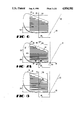
- FIG. 21 is an enlarged cross-sectional view of a parabolic groove in the striking face of the #5 golf iron shown in FIG. 17;
- FIG. 22 is an enlarged cross-section view of a box groove in the striking face of a conventional golf iron
- FIG. 23 is an enlarged sectional view of a V-groove in the striking face of a conventional golf iron
- FIG. 24 is an enlarged cross-sectional view showing the conventional box-groove of FIG. 22 superimposed over the parabolic groove shown in FIG. 21;
- FIG. 25 is a bottom plan view of a #5 golf iron of the present invention.
- FIG. 26 is a schematic representation showing the sole profiles of the set of golf irons of the present invention.
- FIG. 1 there is shown the head of a #5 golf iron 50 embodying the present invention.
- the #5 golf iron shown in FIG. 1 is one of a set of golf irons shown in segmented elevation views in FIGS. 3-13 including a #1 golf iron 10, a #2 golf iron 20, a #3 golf iron 30, a #4 golf iron 40, the #5 golf iron 50, a #6 golf iron 60, a #7 golf iron 70, a #8 golf iron 80, a #9 golf iron 90, a pitching wedge golf iron 100, and a sand wedge golf iron 110.
- each of the golf irons shown in FIGS. 3-13 are identified by a two-digit number in which the first digit identifies the iron number and the second digit identifies the feature.
- the #1 golf iron 10 has a shaft 11.
- the shafts for the other golf irons are identified as 21 for iron #2, 31 for iron #3, and so on ending with 101 identifying the shaft of the pitching wedge and 111 identifying the shaft of the sand wedge.
- the common features will be described in connection with the #5 golf iron shown in FIGS. 7A and 7B.
- the #5 iron 50 has a head 58 with an integral hosel 53, a heel 54, a toe 55, a sole 56, and a striking face 57.
- a shaft 51 is inserted into the hosel 53 and has a shaft axis 52.
- the iron head 58 has a center of mass 59.
- the centers of mass 19, 29, 39, 49, 59, 69, 79, 89, 99, 109, and 119 for each iron in the set are spaced vertically by distances 271-281 above the horizontal plane 135 as set out in Table 2 below.
- the centers of mass are shown projected into the vertical plane 450 (FIG. 19) which includes the axis (eg. 22, 52, or 102) of the shaft and not in the segmented and rotated plane of the iron's face. Consequently, the vertical distances 272, 275, and 280 are measured from the ground plane 135 to the heights of the centers of mass 29, 59, and 109 in the vertical plane 450 (FIG. 19).
- the offset of a golf iron is defined as the horizontal distance between the leading edge of the face of the golf iron and the axis of the shaft.
- FIGS. 16, 17, and 18, there is shown the cross-sections for the #2 iron, #5 iron, and pitching wedge iron.
- the profiles for the #2 iron, #5 iron, and pitching wedge are superimposed on each other in FIG. 19 and are oriented so that the shaft axes 22, 52, and 102, coincide and provide a vertical reference for gauging the offset of each club.
- the three clubs respectively have striking faces 27, 57, and 107 with leading edges 302, 305, and 310.
- each of the clubs respectively has a center of mass 29, 59, and 109.
- the #2 iron 20 has its leading edge 302 behind the vertical reference 22, 52, and 102 in the horizontal direction.
- the #2 iron is said to have a negative offset.
- the pitching wedge 100 has its leading edge 310 in front of the vertical reference of the shaft axes (22, 52, 102) in the horizontal direction so that it is said to have a positive offset.
- the #5 iron 50 typically has it leading edge 305 essentially in line with the vertical reference (22, 52, 102) established by the shaft axes thereby having a neutral or very close to neutral offset.
- the irons of the present invention which have the loft and lie angles shown in Table 1, have an offset in accordance with the following Table 3.
- the offsets of the irons of the present invention illustrated in FIG. 19 are in general conventional.
- the offset as previously noted helps compensate for centrifugal forces because of the distance between the axis of the shaft and the center of mass of the head.
- the centrifugal force on the center of mass of the club head pulls the center of mass downward as indicated by arrow 126 in FIG. 19 for the pitching wedge 100. Consequently, the flex in the shaft 101 causes the loft angle 128 between the face 107 and the axis 102 of the shaft 101 to increase thereby imparting a greater loft and therefore less distance to the golf ball.
- a line 130 which is the center line of the face on each iron, intersects the ground or horizontal plane 135 at a point 134.
- the line 130 is essentially perpendicular to the leading edge of each iron and is aligned with the center of mass of each iron.
- a projection of the shaft axis 52 intersects the horizontal plane 135 at a point 136.
- the distance 145 along the horizontal plane between the points 134 and 136 is the displacement between the center of mass and the axis of the shaft.
- each iron has a different displacement. Referring to FIGS.
- the #1 iron has a displacement 141
- the #2 iron has a displacement 142
- the #3 iron has a displacement 143
- the #4 iron has a displacement 144
- the #5 iron has a displacement 145
- the #6 iron has a displacement 146
- the #7 iron has a displacement 147
- the #8 iron has a displacement 148
- the #9 iron has a displacement 149
- the pitching wedge has a displacement 150
- the sand wedge has a displacement 151.
- the preferred displacements for a set of irons made in accordance with the present invention are set forth in Table 4.
- the displacements shown in Table 4 result from establishing a starting reference with the #1 Long iron (FIG. 3) which in one conventional embodiment has a displacement 141 of 1.5 inch and a lie angle 139 of 57° (Table 1).
- the shaft axis 12 intersects line 130 at a point 137.
- the other displacements 142-151 are determined at the horizontal plane 135 for each lie angle for each iron. If the lie angles are adjusted to accommodate a manufacturer's preference, the displacements should be changed accordingly.
- the rotational moment of inertia is related to the mass of the head and the perpendicular distance 162 from the shaft axis 52. It should be understood that the distance 162 shown in FIG. 7B is not a true representation because the center of mass is displaced into the plane of the drawing.
- the perpendicular distance 162 is 1.5991 inch
- the mass of the head 50 is 251 gms.
- the rotational moment of inertia about the shaft axis 52 can be calculated for each iron by the formula: ##EQU1## where M is the mass, L is the distance 162, and B is the average thickness of the head (equal to approximately 0.4 inch for each iron).
- the golf irons shown in FIGS. 3-13, having the loft angles, the offsets and the displacements disclosed in Tables 1, 3, and 4 have the following perpendicular distances, masses, and moments of inertia shown in Table 5.
- the moments of inertia for the irons in the set are approximately equal within less than 10%. It is believed that variations of as much as 17% will still produce the benefits of the invention.
- the variation is calculated by determining the maximum difference in the moments of inertia between any of the irons in the set (except for the sand wedge) and dividing the difference by the lowest moment of inertia.
- each iron of the set of irons has a reinforcing column behind the center of mass to reinforce the blade of the golf iron and to reduce any hollow or ringing sound that may result.
- the #5 golf iron 50 which is illustrative of all of the irons in the set, has a back side 168 which has a cavity 170 formed therein.
- the cavity 170 is for the purpose of distributing the majority of the mass of the golf iron at the heel 54 and the toe 55 to insure a relatively high rotational moment of inertia about the face center line 130 which passes through the center of mass 59.
- the cavity is of uniform depth centered about the center of mass.
- such a conventional iron has a thin blade 469 (FIG. 20) behind the striking face adjacent the center of mass. Therefore, when a ball is hit with such a conventional iron, the thin blade tends to produce a hollow or ringing sound which many golfers find objectionable.
- the cavity 170 which has side walls 174 and a floor surface 176.
- the floor surface 176 is elevated adjacent the center of mass as the result of the presence of a segment of a support column 180 (FIG. 20).
- the column 180 is positioned behind the striking face 57 (FIG. 17) and has a column axis 182 and a circumference 186.
- the axis 182 is parallel to the striking face 57 and lies within a plane 184 that is perpendicular to the planar face 57 and includes the center of mass 59. As can best be seen in FIG.
- the floor surface 176 of the cavity 170 is defined by the circumference 186 of the column 180 and by fill material 188 which provides a smooth transition from the circumference 186 of the column to a thin periphery 189 adjacent the sides 174.
- the support column 180 with the fill material 188 provides support for the striking face at the center of mass to eliminate the hollow or ringing sound that ordinary results from conventional golf irons which have cavities in the back side.
- the planar striking face 57 of the #5 iron shown in FIG. 7A has a pattern 190 of horizontal grooves 192.
- the pattern 190 is configured so that the space 194 between the grooves 192 is equal for each iron in the set.
- the length 255 of the full length grooves 192 of the #5 iron occupies a majority of the length of face 57.
- the other irons likewise have lengths 251 to 261 for the #1 iron to the sand wedge.
- the groove lengths 251 to 261 vary in direct proportion to the displacements 141-151 of the centers of mass for each iron.
- the specific length of the full length grooves 192 is not critical as long as the groove occupy a majority of the length of the face 57.
- the length of the grooves 192 is proportional to the displacement.
- the pattern of grooves disguises the fact that the irons have the progressive displacement so that the golfer does not subconsciously compensate for the advantages that flow from the progressive displacement.
- the horizontal grooves are for the purpose of channeling away water trapped between the golf ball and the striking face 57 from the point of impact and for providing a frictional surface to assure that back spin is imparted to the ball.
- Horizontal grooves in the prior art have been a groove 193 configured with a V cross-section as shown in FIG. 23 or a groove 195 configured with a box cross-section as shown in FIG. 22.
- Both prior art groove cross-sections have sharp junctions 198 and 200 where the V-shaped groove 193 intersects the striking surface 57 and junctions 202 and 204 where the box-shaped groove 195 joins the striking surface 57. Consequently, the sharp junctions 198, 200, 202, and 204 tend to scuff the ball as they impart back spin to the ball.
- FIG. 21 there is shown the cross-section of one of the horizontal grooves 192 formed in accordance with the present invention.
- the groove 192 in FIG. 21 has two sides 206 and 208 which join the striking face 57 at top junctions 210 and 212.
- the groove also has a planar bottom 214 which joins the sides 206 and 208 at bottom junctions 216 and 218.
- the top junctions 210 and 212 and the major portion of the sides 206 and 208 are defined by a parabola such as 220 for side 206 and top junction 210 and parabola 222 for side 208 and top junction 212.
- the bottom junctions 216 and 218 are defined by radii.
- the parabolic groove 192 can direct more water away from the contact area between the ball and the striking face 57. Also, because the top junctions 210 and 212 are defined by a portion of a parabola, they are not sharp and therefore do not scuff the ball.
- the sole of each golf iron is provided with a flat spot which causes the head to sit squarely when the golf iron is grounded at address.
- the #5 iron 50 having a sole 56 has a flat spot 235 on the sole measuring approximately 0.5" ⁇ 0.2". While the size of the flat spot 235 is not particularly critical, I found that the placement along the length of the sole 57 is of some importance in assisting the golfer in properly grounding the club. With reference to FIG. 26, it can be seen that the flat spot 235 on the #5 iron is located approximately half-way between the leading edge 305 and the trailing edge 325.
- the flat spots 231-241 on the irons 10, 20, 30, 40, 50, 60, 70, 80, 90, 100, and 110 are progressively located between the leading edge and the trailing edge as shown in FIG. 26 in a vertical line with the centers of mass 19, 29, 39, 49, 59, 69, 79, 89, 99, 109, and 119.
Abstract
Description
              TABLE 1
______________________________________
Prior Art
Iron #         Loft Angle
                         Lie Angle
______________________________________
1              16        57
2              18        57.5
3              21        58
4              24        59
5              27.5      60
6              32        60.5
7              37        61
8              41        61.5
9              45        62
Pitching Wedge 50        63
Sand Wedge     58        63
______________________________________
              TABLE 2
______________________________________
               Center of Mass
               Vertical
Iron #         Elevation (inches)
______________________________________
1              .798
2              .795
3              .793
4              .790
5              .787
6              .785
7              .782
8              .779
9              .776
Pitching Wedge .774
Sand Wedge     .774
______________________________________
              TABLE 3
______________________________________
Iron #         Offset (Inches)
______________________________________
1              -0.103
2              -0.082
3              -0.061
4              -0.039
5              -0.018
6              +0.003
7              +0.024
8              +0.046
9              +0.076
Pitching Wedge +0.088
Sand Wedge     +0.099
______________________________________
              TABLE 4
______________________________________
Iron #        Displacement (Inches)
______________________________________
1             1.5
2             1.4715
3             1.4433
4             1.3879
5             1.3336
6             1.3068
7             1.2804
8             1.2541
9             1.2282
Pitching Wedge
              1.1769
Sand Wedge    1.1769
______________________________________
              TABLE 5
______________________________________
                                  Moment
          Perpendicular           of Inertia
Iron #    Distance (inches)
                       Mass(grams)
                                  (lb. ft. sec.sup.2)
______________________________________
1         1.7221       227        4.282 × 10.sup.-4
2         1.7007       224        4.287 × 10.sup.-4
3         1.6809       239        4.296 × 10.sup.-4
4         1.6374       245        4.180 × 10.sup.-4
5         1.5991       251        4.085 × 10.sup.-4
6         1.5851       259        4.142 × 10.sup.-4
7         1.5787       265        4.204 × 10.sup.-4
8         1.5699       270        4.236 × 10.sup.-4
9         1.5600       273        4.261 × 10.sup.-4
Pitching Wedge
          1.5798       279        4.432 × 10.sup.-4
Sand Wedge
          1.5798       285        4.559 × 10.sup.-4
______________________________________
Claims (2)
Priority Applications (1)
| Application Number | Priority Date | Filing Date | Title |
|---|---|---|---|
| US07/193,925 US4854581A (en) | 1987-06-24 | 1988-05-13 | Golf irons |
Applications Claiming Priority (2)
| Application Number | Priority Date | Filing Date | Title |
|---|---|---|---|
| US07/066,077 US4802672A (en) | 1987-06-24 | 1987-06-24 | Set of golf irons |
| US07/193,925 US4854581A (en) | 1987-06-24 | 1988-05-13 | Golf irons |
Related Parent Applications (1)
| Application Number | Title | Priority Date | Filing Date |
|---|---|---|---|
| US07/066,077 Division US4802672A (en) | 1987-06-24 | 1987-06-24 | Set of golf irons |
Publications (1)
| Publication Number | Publication Date |
|---|---|
| US4854581A true US4854581A (en) | 1989-08-08 |
Family
ID=26746342
Family Applications (1)
| Application Number | Title | Priority Date | Filing Date |
|---|---|---|---|
| US07/193,925 Expired - Fee Related US4854581A (en) | 1987-06-24 | 1988-05-13 | Golf irons |
Country Status (1)
| Country | Link |
|---|---|
| US (1) | US4854581A (en) |
Cited By (64)
| Publication number | Priority date | Publication date | Assignee | Title |
|---|---|---|---|---|
| US4995609A (en) * | 1987-02-27 | 1991-02-26 | Callaway Golf Company | Iron golf club heads |
| US5067711A (en) * | 1989-04-10 | 1991-11-26 | Callaway Golf Company | Iron golf club heads |
| US5082278A (en) * | 1990-04-12 | 1992-01-21 | Hsien James C | Golf club head with variable center of gravity |
| US5120062A (en) * | 1990-07-26 | 1992-06-09 | Wilson Sporting Goods Co. | Golf club head with high toe and low heel weighting |
| US5160137A (en) * | 1988-09-02 | 1992-11-03 | Maruman Golf Kabushiki Kaisha | Iron golf club set |
| US5165688A (en) * | 1991-08-09 | 1992-11-24 | Callaway Golf Company | Golf club head to shaft connection |
| US5222734A (en) * | 1987-02-27 | 1993-06-29 | Callaway Golf Company | Iron golf club heads |
| US5224705A (en) * | 1990-07-26 | 1993-07-06 | Wilson Sporting Goods Co. | Golf club head with high toe and low heel weighting |
| US5282625A (en) * | 1992-08-05 | 1994-02-01 | Callaway Golf Company | Iron golf club head with dual intersecting recesses |
| US5290032A (en) * | 1990-04-02 | 1994-03-01 | Lisco, Inc. | Iron with progessive back cavity support bar |
| US5301946A (en) * | 1992-08-05 | 1994-04-12 | Callaway Golf Company | Iron golf club head with dual intersecting recesses and associated slits |
| US5306008A (en) * | 1992-09-04 | 1994-04-26 | Frank Kinoshita | Momentum transfer golf club |
| US5320347A (en) * | 1987-02-27 | 1994-06-14 | Callaway Golf Company | Iron golf club heads |
| US5330187A (en) * | 1992-08-05 | 1994-07-19 | Callaway Golf Company | Iron golf club head with dual intersecting recesses |
| US5333872A (en) * | 1993-01-21 | 1994-08-02 | Hillerich & Bradsby Co., Inc. | Golf club irons having improved weighting |
| US5344150A (en) * | 1992-08-05 | 1994-09-06 | Callaway Golf Company | Iron golf club head with straight, horizontal recess |
| US5377978A (en) * | 1994-07-05 | 1995-01-03 | Lee; Michael C. W. | Golf club hosel shift |
| US5388826A (en) * | 1994-02-14 | 1995-02-14 | Sherwood; Brad L. | Correlated set of golf club irons |
| US5409229A (en) * | 1992-08-05 | 1995-04-25 | Callaway Golf Company | Golf club head with audible vibration attenuation |
| US5419560A (en) * | 1994-03-15 | 1995-05-30 | Bamber; Jeffrey V. | Perimeter weighted golf clubs |
| US5433439A (en) * | 1993-09-15 | 1995-07-18 | Hsien; James C. | Golf club set having progressively offset faces |
| US5460377A (en) * | 1992-08-05 | 1995-10-24 | Callaway Golf Company | Golf putter with face plate insert |
| US5464218A (en) * | 1994-07-07 | 1995-11-07 | Callaway Golf Company | Golf putter head with undercut back cavity and peripheral weighting |
| US5472203A (en) * | 1992-08-05 | 1995-12-05 | Callaway Golf Company | Iron golf club head with dual intersecting recesses |
| US5480152A (en) * | 1990-10-16 | 1996-01-02 | Callaway Golf Company | Hollow, metallic golf club head with relieved sole and dendritic structure |
| US5485997A (en) * | 1992-08-05 | 1996-01-23 | Callaway Golf Company | Golf putter head with face plate insert having heightened medial portion |
| US5529543A (en) * | 1994-12-06 | 1996-06-25 | Beaumont, Sr.; Gregory J. | Golf irons with increased consistency |
| US5540437A (en) * | 1994-03-15 | 1996-07-30 | Bamber; Jeffrey V. | Perimeter weighted golf clubs |
| US5588923A (en) * | 1992-08-05 | 1996-12-31 | Callaway Golf Company | Golf club head with attached selected swing weight composite |
| USD377818S (en) * | 1996-01-16 | 1997-02-04 | Callaway Golf Company | Golf putter head with multi-arcuate configuration |
| USD378113S (en) * | 1996-01-16 | 1997-02-18 | Callaway Golf Company | Golf putter head with fluted rear side and stepped top wall |
| US5626530A (en) * | 1992-08-05 | 1997-05-06 | Callaway Golf Company | Golf club head with sole bevel indicia |
| US5645495A (en) * | 1991-05-01 | 1997-07-08 | Himeji Lodge Hakuba Co., Ltd. | Golf club |
| US5658209A (en) * | 1994-06-27 | 1997-08-19 | John T. Godwin | Golf club head with optimum distributed mass contour |
| US5665009A (en) * | 1996-08-08 | 1997-09-09 | Sherwood; Brad L. | Correlated set of golf club irons |
| USD383512S (en) * | 1994-06-20 | 1997-09-09 | Callaway Golf Company | Golf putter head with undercut cavity back |
| USD385933S (en) * | 1996-01-16 | 1997-11-04 | Callaway Golf Company | Golf putter head with recessed and fluted rear side |
| USD387830S (en) * | 1996-08-23 | 1997-12-16 | Gilbert Peter J | Portion of a sole of a golf club head |
| US5697853A (en) * | 1990-10-16 | 1997-12-16 | Callaway Golf Company | Hollow, metallic golf club head with relieved sole and dendritic structure |
| USD388851S (en) | 1996-01-16 | 1998-01-06 | Callaway Golf Company | Golf putter head with recessed and fluted rear side and stepped top wall |
| US5766087A (en) * | 1996-01-23 | 1998-06-16 | Sumitomo Rubber Industries, Ltd. | Set of golf clubs |
| US5776010A (en) * | 1997-01-22 | 1998-07-07 | Callaway Golf Company | Weight structure on a golf club head |
| WO1998031433A1 (en) * | 1997-01-22 | 1998-07-23 | Callaway Golf Company | Inertially tailored golf club heads |
| US5785605A (en) * | 1996-01-11 | 1998-07-28 | Callaway Golf Company | Hollow, metallic golf club head with configured medial ridge |
| USD401651S (en) | 1997-10-31 | 1998-11-24 | Callaway Golf Company | Golf putter head and angled hosel |
| USD402343S (en) | 1997-10-31 | 1998-12-08 | Callaway Golf Company | Golf putter head |
| USD402344S (en) | 1997-10-28 | 1998-12-08 | Callaway Golf Company | Golf putter head with curved flutes and a curved hosel |
| USD402722S (en) | 1997-10-28 | 1998-12-15 | Callaway Golf Company | Golf putter head with flutes and angled hosel |
| USD407445S (en) | 1997-03-10 | 1999-03-30 | Callaway Golf Company | Golf putter head with recessed and curved and fluted rear side |
| USD414830S (en) | 1997-10-28 | 1999-10-05 | Callaway Golf Company | Golf putter with angled hosel and recess-intercepting, curved flutes at rear side |
| US6007433A (en) * | 1998-04-02 | 1999-12-28 | Callaway Golf Company | Sole configuration for golf club head |
| USD420081S (en) * | 1998-04-01 | 2000-02-01 | Callaway Golf Company | Sole design for golf club head |
| US6168536B1 (en) | 1997-12-30 | 2001-01-02 | Love It Golf Company | Golf club head |
| US6569031B2 (en) * | 2000-07-14 | 2003-05-27 | Kasco Corporation | Iron club head |
| US20090036228A1 (en) * | 2007-08-02 | 2009-02-05 | Bridgestone Sports Co., Ltd. | Method of manufacturing golf club head and golf club head |
| US20090082129A1 (en) * | 2007-09-26 | 2009-03-26 | Bridgestone Sports Co., Ltd. | Method of Manufacturing Golf Club Head and Golf Club Head |
| US20100093459A1 (en) * | 2008-10-13 | 2010-04-15 | Cole Eric V | Club Heads With Contoured Back Faces And Methods Of Manufacturing The Same |
| US20100093461A1 (en) * | 2008-10-13 | 2010-04-15 | Cole Eric V | Club Heads With Contoured Back Faces And Methods Of Manufacturing The Same |
| US20110105240A1 (en) * | 2009-10-30 | 2011-05-05 | Hiroshi Abe | Golf club set |
| US20160101330A1 (en) * | 2014-10-08 | 2016-04-14 | Acushnet Company | Golf club head with variable center of gravity |
| US20180256947A1 (en) * | 2015-02-19 | 2018-09-13 | Acushnet Company | Weighted iron set |
| US20180296883A1 (en) * | 2017-04-14 | 2018-10-18 | Sumitomo Rubber Industries, Ltd. | Golf club set |
| US20180311540A1 (en) * | 2017-04-28 | 2018-11-01 | Sumitomo Rubber Industries, Ltd. | Golf club set |
| US10423945B2 (en) * | 2016-12-31 | 2019-09-24 | Taylor Made Golf Company, Inc. | Golf club head and method of manufacture |
Citations (3)
| Publication number | Priority date | Publication date | Assignee | Title |
|---|---|---|---|---|
| GB160030A (en) * | 1920-01-03 | 1921-03-17 | Harold John Kinsman | Improvements in or relating to golf clubs |
| US3035839A (en) * | 1960-11-02 | 1962-05-22 | Michael W Coglianese | Golf club |
| US3845955A (en) * | 1972-10-04 | 1974-11-05 | K Solheim | Gold club indicia |
-
1988
- 1988-05-13 US US07/193,925 patent/US4854581A/en not_active Expired - Fee Related
Patent Citations (3)
| Publication number | Priority date | Publication date | Assignee | Title |
|---|---|---|---|---|
| GB160030A (en) * | 1920-01-03 | 1921-03-17 | Harold John Kinsman | Improvements in or relating to golf clubs |
| US3035839A (en) * | 1960-11-02 | 1962-05-22 | Michael W Coglianese | Golf club |
| US3845955A (en) * | 1972-10-04 | 1974-11-05 | K Solheim | Gold club indicia |
Cited By (107)
| Publication number | Priority date | Publication date | Assignee | Title |
|---|---|---|---|---|
| US4995609A (en) * | 1987-02-27 | 1991-02-26 | Callaway Golf Company | Iron golf club heads |
| US5320347A (en) * | 1987-02-27 | 1994-06-14 | Callaway Golf Company | Iron golf club heads |
| US5222734A (en) * | 1987-02-27 | 1993-06-29 | Callaway Golf Company | Iron golf club heads |
| US5160137A (en) * | 1988-09-02 | 1992-11-03 | Maruman Golf Kabushiki Kaisha | Iron golf club set |
| US5067711A (en) * | 1989-04-10 | 1991-11-26 | Callaway Golf Company | Iron golf club heads |
| US5290032A (en) * | 1990-04-02 | 1994-03-01 | Lisco, Inc. | Iron with progessive back cavity support bar |
| US5082278A (en) * | 1990-04-12 | 1992-01-21 | Hsien James C | Golf club head with variable center of gravity |
| US5120062A (en) * | 1990-07-26 | 1992-06-09 | Wilson Sporting Goods Co. | Golf club head with high toe and low heel weighting |
| US5224705A (en) * | 1990-07-26 | 1993-07-06 | Wilson Sporting Goods Co. | Golf club head with high toe and low heel weighting |
| US6027416A (en) * | 1990-10-16 | 2000-02-22 | Callaway Golf Company | Hollow, metallic golf club head with relieved sole and dendritic structure |
| US5697853A (en) * | 1990-10-16 | 1997-12-16 | Callaway Golf Company | Hollow, metallic golf club head with relieved sole and dendritic structure |
| US5480152A (en) * | 1990-10-16 | 1996-01-02 | Callaway Golf Company | Hollow, metallic golf club head with relieved sole and dendritic structure |
| US5645495A (en) * | 1991-05-01 | 1997-07-08 | Himeji Lodge Hakuba Co., Ltd. | Golf club |
| US5275399A (en) * | 1991-08-09 | 1994-01-04 | Callaway Golf Company | Golf club head to shaft connection |
| US5165688A (en) * | 1991-08-09 | 1992-11-24 | Callaway Golf Company | Golf club head to shaft connection |
| US5485997A (en) * | 1992-08-05 | 1996-01-23 | Callaway Golf Company | Golf putter head with face plate insert having heightened medial portion |
| US5441264A (en) * | 1992-08-05 | 1995-08-15 | Callaway Golf Company | Iron golf club head with straight, horizontal recess |
| US5588923A (en) * | 1992-08-05 | 1996-12-31 | Callaway Golf Company | Golf club head with attached selected swing weight composite |
| US5704849A (en) * | 1992-08-05 | 1998-01-06 | Callaway Golf Company | Golf club head with audible vibration attenuation |
| US5409229A (en) * | 1992-08-05 | 1995-04-25 | Callaway Golf Company | Golf club head with audible vibration attenuation |
| US5282625A (en) * | 1992-08-05 | 1994-02-01 | Callaway Golf Company | Iron golf club head with dual intersecting recesses |
| US5588922A (en) * | 1992-08-05 | 1996-12-31 | Callaway Golf Company | Iron golf club head with forwardly divergent interior recess |
| US5344150A (en) * | 1992-08-05 | 1994-09-06 | Callaway Golf Company | Iron golf club head with straight, horizontal recess |
| US5437456A (en) * | 1992-08-05 | 1995-08-01 | Callaway Golf Company | Iron golf club head with dual intersecting recesses and associated slits |
| US5301946A (en) * | 1992-08-05 | 1994-04-12 | Callaway Golf Company | Iron golf club head with dual intersecting recesses and associated slits |
| US5460377A (en) * | 1992-08-05 | 1995-10-24 | Callaway Golf Company | Golf putter with face plate insert |
| US5626530A (en) * | 1992-08-05 | 1997-05-06 | Callaway Golf Company | Golf club head with sole bevel indicia |
| US5472203A (en) * | 1992-08-05 | 1995-12-05 | Callaway Golf Company | Iron golf club head with dual intersecting recesses |
| US5605511A (en) * | 1992-08-05 | 1997-02-25 | Callaway Golf Company | Golf club head with audible vibration attenuation |
| US5330187A (en) * | 1992-08-05 | 1994-07-19 | Callaway Golf Company | Iron golf club head with dual intersecting recesses |
| US5749795A (en) * | 1992-08-05 | 1998-05-12 | Callaway Golf Company | Iron golf club head with dual intersecting recesses |
| US5605510A (en) * | 1992-08-05 | 1997-02-25 | Callaway Golf Company | Golf putter with face plate insert |
| US5306008A (en) * | 1992-09-04 | 1994-04-26 | Frank Kinoshita | Momentum transfer golf club |
| US5423546A (en) * | 1993-01-21 | 1995-06-13 | Hillerich & Bradsbry Co., Inc. | Golf club irons having improved weighting |
| US5333872A (en) * | 1993-01-21 | 1994-08-02 | Hillerich & Bradsby Co., Inc. | Golf club irons having improved weighting |
| US5433439A (en) * | 1993-09-15 | 1995-07-18 | Hsien; James C. | Golf club set having progressively offset faces |
| US6196934B1 (en) | 1994-02-14 | 2001-03-06 | Sherwood Investments, Inc. | Correlated set of golf club irons |
| US6547675B2 (en) | 1994-02-14 | 2003-04-15 | U. I. G., Inc. | Correlated set of golf club irons |
| US5480145A (en) * | 1994-02-14 | 1996-01-02 | Sherwood; Brad L. | Correlated set of golf club irons |
| US20040259658A1 (en) * | 1994-02-14 | 2004-12-23 | Sherwood Brad L | Correlated set of golf club irons |
| US6863621B2 (en) | 1994-02-14 | 2005-03-08 | U.I.G., Inc. | Correlated set of golf club irons |
| US5388826A (en) * | 1994-02-14 | 1995-02-14 | Sherwood; Brad L. | Correlated set of golf club irons |
| US7022033B2 (en) | 1994-03-15 | 2006-04-04 | Pelican Golf, Inc. | Perimeter weighted golf clubs |
| US5827132A (en) * | 1994-03-15 | 1998-10-27 | Pelican Golf, Inc. | Perimeter weighted golf clubs |
| US5669830A (en) * | 1994-03-15 | 1997-09-23 | Bamber; Jeffrey Vincent | Perimeter weighted golf clubs |
| US20030073511A1 (en) * | 1994-03-15 | 2003-04-17 | Bamber Jeffrey Vincent | Perimeter weighted golf clubs |
| US6702693B2 (en) | 1994-03-15 | 2004-03-09 | Pelican Golf, Inc. | Perimeter weighted golf clubs |
| US5419560A (en) * | 1994-03-15 | 1995-05-30 | Bamber; Jeffrey V. | Perimeter weighted golf clubs |
| US5540437A (en) * | 1994-03-15 | 1996-07-30 | Bamber; Jeffrey V. | Perimeter weighted golf clubs |
| US7128663B2 (en) | 1994-03-15 | 2006-10-31 | Pelican Golf, Inc. | Perimeter weighted golf clubs |
| USD383512S (en) * | 1994-06-20 | 1997-09-09 | Callaway Golf Company | Golf putter head with undercut cavity back |
| US5658209A (en) * | 1994-06-27 | 1997-08-19 | John T. Godwin | Golf club head with optimum distributed mass contour |
| US5377978A (en) * | 1994-07-05 | 1995-01-03 | Lee; Michael C. W. | Golf club hosel shift |
| US5464218A (en) * | 1994-07-07 | 1995-11-07 | Callaway Golf Company | Golf putter head with undercut back cavity and peripheral weighting |
| US5529543A (en) * | 1994-12-06 | 1996-06-25 | Beaumont, Sr.; Gregory J. | Golf irons with increased consistency |
| US5976029A (en) * | 1995-02-13 | 1999-11-02 | Brad L. Sherwood | Correlated set of golf club irons |
| US5785605A (en) * | 1996-01-11 | 1998-07-28 | Callaway Golf Company | Hollow, metallic golf club head with configured medial ridge |
| USD385933S (en) * | 1996-01-16 | 1997-11-04 | Callaway Golf Company | Golf putter head with recessed and fluted rear side |
| USD388851S (en) | 1996-01-16 | 1998-01-06 | Callaway Golf Company | Golf putter head with recessed and fluted rear side and stepped top wall |
| USD378113S (en) * | 1996-01-16 | 1997-02-18 | Callaway Golf Company | Golf putter head with fluted rear side and stepped top wall |
| USD377818S (en) * | 1996-01-16 | 1997-02-04 | Callaway Golf Company | Golf putter head with multi-arcuate configuration |
| US5766087A (en) * | 1996-01-23 | 1998-06-16 | Sumitomo Rubber Industries, Ltd. | Set of golf clubs |
| US5665009A (en) * | 1996-08-08 | 1997-09-09 | Sherwood; Brad L. | Correlated set of golf club irons |
| USD387830S (en) * | 1996-08-23 | 1997-12-16 | Gilbert Peter J | Portion of a sole of a golf club head |
| US5776010A (en) * | 1997-01-22 | 1998-07-07 | Callaway Golf Company | Weight structure on a golf club head |
| US6045455A (en) * | 1997-01-22 | 2000-04-04 | Callaway Golf Company | Inertially tailored golf club heads |
| WO1998031433A1 (en) * | 1997-01-22 | 1998-07-23 | Callaway Golf Company | Inertially tailored golf club heads |
| USD407445S (en) | 1997-03-10 | 1999-03-30 | Callaway Golf Company | Golf putter head with recessed and curved and fluted rear side |
| USD402344S (en) | 1997-10-28 | 1998-12-08 | Callaway Golf Company | Golf putter head with curved flutes and a curved hosel |
| USD414830S (en) | 1997-10-28 | 1999-10-05 | Callaway Golf Company | Golf putter with angled hosel and recess-intercepting, curved flutes at rear side |
| USD402722S (en) | 1997-10-28 | 1998-12-15 | Callaway Golf Company | Golf putter head with flutes and angled hosel |
| USD401651S (en) | 1997-10-31 | 1998-11-24 | Callaway Golf Company | Golf putter head and angled hosel |
| USD402343S (en) | 1997-10-31 | 1998-12-08 | Callaway Golf Company | Golf putter head |
| US6932714B2 (en) * | 1997-12-30 | 2005-08-23 | Love It Golf Company | Golf club head |
| US20030199336A1 (en) * | 1997-12-30 | 2003-10-23 | Lovett Golf Company | Golf club head |
| US6565451B1 (en) * | 1997-12-30 | 2003-05-20 | Lovett Golf Company | Golf club head |
| US6168536B1 (en) | 1997-12-30 | 2001-01-02 | Love It Golf Company | Golf club head |
| USD420081S (en) * | 1998-04-01 | 2000-02-01 | Callaway Golf Company | Sole design for golf club head |
| US6007433A (en) * | 1998-04-02 | 1999-12-28 | Callaway Golf Company | Sole configuration for golf club head |
| US6165077A (en) * | 1998-04-02 | 2000-12-26 | Callaway Golf Company | Sole configuration for golf club head |
| US6569031B2 (en) * | 2000-07-14 | 2003-05-27 | Kasco Corporation | Iron club head |
| US20090036228A1 (en) * | 2007-08-02 | 2009-02-05 | Bridgestone Sports Co., Ltd. | Method of manufacturing golf club head and golf club head |
| US20090082129A1 (en) * | 2007-09-26 | 2009-03-26 | Bridgestone Sports Co., Ltd. | Method of Manufacturing Golf Club Head and Golf Club Head |
| US7914394B2 (en) * | 2008-10-13 | 2011-03-29 | Karsten Manufacturing Corporation | Club heads with contoured back faces and methods of manufacturing the same |
| US20100093461A1 (en) * | 2008-10-13 | 2010-04-15 | Cole Eric V | Club Heads With Contoured Back Faces And Methods Of Manufacturing The Same |
| US7794335B2 (en) * | 2008-10-13 | 2010-09-14 | Karsten Manufacturing Corporation | Club heads with contoured back faces and methods of manufacturing the same |
| US20100279790A1 (en) * | 2008-10-13 | 2010-11-04 | Karsten Manufacturing Corporation | Club Heads With Contoured Back Faces And Methos Of Manufacturing The Same |
| US20100093459A1 (en) * | 2008-10-13 | 2010-04-15 | Cole Eric V | Club Heads With Contoured Back Faces And Methods Of Manufacturing The Same |
| US20110118055A1 (en) * | 2008-10-13 | 2011-05-19 | Cole Eric V | Club heads with contoured back faces and methods of manufacturing the same |
| US8221264B2 (en) | 2008-10-13 | 2012-07-17 | Karsten Manufacturing Corporation | Club heads with contoured back faces and methods of manufacturing the same |
| US8235842B2 (en) * | 2008-10-13 | 2012-08-07 | Karsten Manufacturing Corporation | Club heads with contoured back faces and methods of manufacturing the same |
| US8616998B2 (en) | 2008-10-13 | 2013-12-31 | Karsten Manufacturing Corporation | Club heads with contoured back faces and methods of manufacturing the same |
| US20110105240A1 (en) * | 2009-10-30 | 2011-05-05 | Hiroshi Abe | Golf club set |
| US8409029B2 (en) * | 2009-10-30 | 2013-04-02 | Sri Sports Limited | Golf club set |
| US20160101330A1 (en) * | 2014-10-08 | 2016-04-14 | Acushnet Company | Golf club head with variable center of gravity |
| US20180256947A1 (en) * | 2015-02-19 | 2018-09-13 | Acushnet Company | Weighted iron set |
| US10463933B2 (en) * | 2015-02-19 | 2019-11-05 | Acushnet Company | Weighted iron set |
| US10881924B2 (en) | 2015-02-19 | 2021-01-05 | Acushnet Company | Weighted iron set |
| US11478684B2 (en) | 2015-02-19 | 2022-10-25 | Acushnet Company | Weighted iron set |
| US10423945B2 (en) * | 2016-12-31 | 2019-09-24 | Taylor Made Golf Company, Inc. | Golf club head and method of manufacture |
| US11004046B2 (en) * | 2016-12-31 | 2021-05-11 | Taylor Made Golf Company, Inc. | Golf club head and method of manufacture |
| US11164171B2 (en) * | 2016-12-31 | 2021-11-02 | Taylor Made Golf Company, Inc. | Golf club head and method of manufacture |
| US11907923B2 (en) | 2016-12-31 | 2024-02-20 | Taylor Made Golf Company, Inc. | Golf club head and method of manufacture |
| US20180296883A1 (en) * | 2017-04-14 | 2018-10-18 | Sumitomo Rubber Industries, Ltd. | Golf club set |
| US10493337B2 (en) * | 2017-04-14 | 2019-12-03 | Sumitomo Rubber Industries, Ltd. | Golf club set |
| US20180311540A1 (en) * | 2017-04-28 | 2018-11-01 | Sumitomo Rubber Industries, Ltd. | Golf club set |
| US10478682B2 (en) * | 2017-04-28 | 2019-11-19 | Sumitomo Rubber Industries, Ltd. | Golf club set |
Similar Documents
| Publication | Publication Date | Title |
|---|---|---|
| US4854581A (en) | Golf irons | |
| US4957294A (en) | Golf club head | |
| US4802672A (en) | Set of golf irons | |
| US4858929A (en) | Golf irons | |
| US5333872A (en) | Golf club irons having improved weighting | |
| US4420156A (en) | Iron-type golf clubs | |
| US5658209A (en) | Golf club head with optimum distributed mass contour | |
| US5120062A (en) | Golf club head with high toe and low heel weighting | |
| US4471961A (en) | Golf club with bulge radius and increased moment of inertia about an inclined axis | |
| US4498673A (en) | Golf club | |
| US5335914A (en) | Golf club head | |
| US5547426A (en) | Progressive golf club having a diagonally balanced slot back | |
| US4913435A (en) | Golf club and a set of golf clubs | |
| US4944515A (en) | Hollow golf club head with internal support | |
| US5326105A (en) | Sea plane sole for a golf club | |
| US4762322A (en) | Golf club | |
| US3655188A (en) | Correlated golf club set | |
| US5094457A (en) | Low axial inertia golf club | |
| US5209473A (en) | Set of golf clubs having oval shape cavity back | |
| US5544884A (en) | Golf club with skewed sole | |
| US5224705A (en) | Golf club head with high toe and low heel weighting | |
| US20070078030A1 (en) | Iron-type golf club head with sole having stable static address position | |
| US5501460A (en) | Golf club set with constant projected topline angle | |
| JPS6031740Y2 (en) | iron club set | |
| JPH0671487B2 (en) | Iron club head |
Legal Events
| Date | Code | Title | Description |
|---|---|---|---|
| FEPP | Fee payment procedure |
Free format text: PAYOR NUMBER ASSIGNED (ORIGINAL EVENT CODE: ASPN); ENTITY STATUS OF PATENT OWNER: LARGE ENTITY |
|
| FPAY | Fee payment |
Year of fee payment: 4 |
|
| FPAY | Fee payment |
Year of fee payment: 8 |
|
| AS | Assignment |
Owner name: MGC HOLDING INC., A CORP OF DELAWARE, GEORGIA Free format text: ASSIGNMENT OF ASSIGNORS INTEREST;ASSIGNOR:MACGREGOR GOLF COMPANY;REEL/FRAME:008568/0522 Effective date: 19970131 |
|
| AS | Assignment |
Owner name: MACGREGOR GOLF COMPANY, GEORGIA Free format text: CHANGE OF NAME;ASSIGNOR:MGC HOLDING INC.;REEL/FRAME:008545/0939 Effective date: 19970204 |
|
| AS | Assignment |
Owner name: CONGRESS FINANCIAL CORPORATION (WESTERN), CALIFORN Free format text: SECURITY AGREEMENT;ASSIGNOR:MACGREGOR GOLF COMPANY;REEL/FRAME:009845/0782 Effective date: 19990319 |
|
| REMI | Maintenance fee reminder mailed | ||
| LAPS | Lapse for failure to pay maintenance fees | ||
| FP | Lapsed due to failure to pay maintenance fee |
Effective date: 20010808 |
|
| AS | Assignment |
Owner name: MACGREGOR GOLF COMPANY, GEORGIA Free format text: NOTICE OF RELEASE OF SECURITY INTEREST IN PATENTS;ASSIGNOR:CONGRESS FINANCIAL CORPORATION (WESTERN);REEL/FRAME:012973/0547 Effective date: 20020530 |
|
| AS | Assignment |
Owner name: FOOTHILL CAPITAL CORPORATION, GEORGIA Free format text: SECURITY INTEREST;ASSIGNOR:MACGREGOR GOLF COMPANY;REEL/FRAME:013077/0244 Effective date: 20020701 |
|
| STCH | Information on status: patent discontinuation |
Free format text: PATENT EXPIRED DUE TO NONPAYMENT OF MAINTENANCE FEES UNDER 37 CFR 1.362 |