US4850693A - Compact portable diffraction moire interferometer - Google Patents
Compact portable diffraction moire interferometer Download PDFInfo
- Publication number
- US4850693A US4850693A US07/197,235 US19723588A US4850693A US 4850693 A US4850693 A US 4850693A US 19723588 A US19723588 A US 19723588A US 4850693 A US4850693 A US 4850693A
- Authority
- US
- United States
- Prior art keywords
- interferometer
- beams
- diffraction
- laser
- grating
- Prior art date
- Legal status (The legal status is an assumption and is not a legal conclusion. Google has not performed a legal analysis and makes no representation as to the accuracy of the status listed.)
- Expired - Lifetime
Links
- 239000000835 fiber Substances 0.000 claims abstract description 34
- 230000008878 coupling Effects 0.000 claims abstract description 5
- 238000010168 coupling process Methods 0.000 claims abstract description 5
- 238000005859 coupling reaction Methods 0.000 claims abstract description 5
- 230000001427 coherent effect Effects 0.000 claims description 18
- 238000000034 method Methods 0.000 claims description 16
- 239000013307 optical fiber Substances 0.000 claims description 9
- 230000010287 polarization Effects 0.000 claims description 6
- 230000003287 optical effect Effects 0.000 abstract description 7
- 238000005305 interferometry Methods 0.000 description 15
- 238000003384 imaging method Methods 0.000 description 9
- 239000000463 material Substances 0.000 description 8
- 238000010586 diagram Methods 0.000 description 7
- 238000006073 displacement reaction Methods 0.000 description 5
- 230000035945 sensitivity Effects 0.000 description 5
- 238000001914 filtration Methods 0.000 description 3
- 238000005259 measurement Methods 0.000 description 3
- 229910052782 aluminium Inorganic materials 0.000 description 2
- XAGFODPZIPBFFR-UHFFFAOYSA-N aluminium Chemical compound [Al] XAGFODPZIPBFFR-UHFFFAOYSA-N 0.000 description 2
- 230000000712 assembly Effects 0.000 description 2
- 238000000429 assembly Methods 0.000 description 2
- 239000000969 carrier Substances 0.000 description 2
- 230000001419 dependent effect Effects 0.000 description 2
- 238000012986 modification Methods 0.000 description 2
- 230000004048 modification Effects 0.000 description 2
- 238000000926 separation method Methods 0.000 description 2
- 230000000903 blocking effect Effects 0.000 description 1
- 230000008859 change Effects 0.000 description 1
- 238000000576 coating method Methods 0.000 description 1
- 230000006835 compression Effects 0.000 description 1
- 238000007906 compression Methods 0.000 description 1
- 230000001066 destructive effect Effects 0.000 description 1
- 230000000694 effects Effects 0.000 description 1
- 238000005210 holographic interferometry Methods 0.000 description 1
- 238000001093 holography Methods 0.000 description 1
- 238000005286 illumination Methods 0.000 description 1
- 238000004519 manufacturing process Methods 0.000 description 1
- 230000007246 mechanism Effects 0.000 description 1
- 229910052751 metal Inorganic materials 0.000 description 1
- 239000002184 metal Substances 0.000 description 1
- 238000009659 non-destructive testing Methods 0.000 description 1
- 230000008569 process Effects 0.000 description 1
- 238000011160 research Methods 0.000 description 1
- 230000037380 skin damage Effects 0.000 description 1
- 230000003595 spectral effect Effects 0.000 description 1
- 238000001228 spectrum Methods 0.000 description 1
- 230000007480 spreading Effects 0.000 description 1
- 238000010561 standard procedure Methods 0.000 description 1
- 239000000758 substrate Substances 0.000 description 1
- 238000012549 training Methods 0.000 description 1
Images


Classifications
-
- G—PHYSICS
- G01—MEASURING; TESTING
- G01B—MEASURING LENGTH, THICKNESS OR SIMILAR LINEAR DIMENSIONS; MEASURING ANGLES; MEASURING AREAS; MEASURING IRREGULARITIES OF SURFACES OR CONTOURS
- G01B11/00—Measuring arrangements characterised by the use of optical techniques
- G01B11/16—Measuring arrangements characterised by the use of optical techniques for measuring the deformation in a solid, e.g. optical strain gauge
- G01B11/165—Measuring arrangements characterised by the use of optical techniques for measuring the deformation in a solid, e.g. optical strain gauge by means of a grating deformed by the object
-
- G—PHYSICS
- G01—MEASURING; TESTING
- G01D—MEASURING NOT SPECIALLY ADAPTED FOR A SPECIFIC VARIABLE; ARRANGEMENTS FOR MEASURING TWO OR MORE VARIABLES NOT COVERED IN A SINGLE OTHER SUBCLASS; TARIFF METERING APPARATUS; MEASURING OR TESTING NOT OTHERWISE PROVIDED FOR
- G01D5/00—Mechanical means for transferring the output of a sensing member; Means for converting the output of a sensing member to another variable where the form or nature of the sensing member does not constrain the means for converting; Transducers not specially adapted for a specific variable
- G01D5/26—Mechanical means for transferring the output of a sensing member; Means for converting the output of a sensing member to another variable where the form or nature of the sensing member does not constrain the means for converting; Transducers not specially adapted for a specific variable characterised by optical transfer means, i.e. using infrared, visible, or ultraviolet light
- G01D5/32—Mechanical means for transferring the output of a sensing member; Means for converting the output of a sensing member to another variable where the form or nature of the sensing member does not constrain the means for converting; Transducers not specially adapted for a specific variable characterised by optical transfer means, i.e. using infrared, visible, or ultraviolet light with attenuation or whole or partial obturation of beams of light
- G01D5/34—Mechanical means for transferring the output of a sensing member; Means for converting the output of a sensing member to another variable where the form or nature of the sensing member does not constrain the means for converting; Transducers not specially adapted for a specific variable characterised by optical transfer means, i.e. using infrared, visible, or ultraviolet light with attenuation or whole or partial obturation of beams of light the beams of light being detected by photocells
- G01D5/36—Forming the light into pulses
- G01D5/38—Forming the light into pulses by diffraction gratings
Definitions
- This invention relates to an interferometer and more particularly to a compact, portable diffraction moire interferometer useful for determining material distortion and strain.
- Applicant provides a compact, portable device, easily used by an inexperienced operator, utilizing the technique of diffraction moire interferometry.
- the technique of diffraction moire interferometry and diffraction grating interferometry upon which it is based, is directly sensitive to in-plane displacements (unlike holography, photoelasticity and strain gauges), provides full field data over a substantial area (unlike strain gauges), provides excellent, variable resolution, and, finally, provides very high quality data, not degraded by laser speckle (as with holographic and speckle interferometry).
- interferometer may be applied to any arrangement whereby a beam of light is separated into two or more parts, the parts being subsequently reunited after traversing different optical paths.
- Diffraction moire interferometry uses a reflective-type diffraction grating (i.e. a specimen grating) which is fixed to the object under study and illuminated by two mutually coherent collimated beams. If the illuminating beams are set at the proper incidence angles, the plus first diffraction order of one illuminating beam and the minus first diffraction order of the other beam coincide in space along a line normal to the specimen.
- interference fringes (sometimes called moire patterns) representing a contour map of in-plane displacements can be observed. Comparison of fringes before and after loading can be used to determine load-induced displacements.
- Sensitivity of the technique is dependent upon the frequency of the diffraction grating placed on the specimen and on the wavelength used to illuminate the grating. Sensitivities of better than 0.5 micrometer are routinely obtained, and various interpolations can further extend this resolution.
- Moire deflectometry has been preferred to diffraction moire interferometry because it involves very simple alignment and therefore is much easier and less expensive to set up (see for example, U.S. Pat. No. 4,459,027, Kafri et al., and U.S. Pat. No. 4,577,940, Krasinski et al.).
- coarse moire does not provide adequate resolution for many modern applications.
- this invention comprises a novel improved compact and portable moire interferometer used to determine surface deformations of an object.
- the improved interferometer is comprised of a laser beam, optical and fiber optics devices coupling the beam to one or more evanescent wave splitters, and collimating lenses directing the split beam at the specimen grating. Means are provided for viewing the resultant fringe patterns.
- the system is portable and can be used on-site.
- Set up and alignment time averages about 20 minutes, and similar time is all that is required if the system or grating is changed during operation. Operator training is considerably reduced.
- FIG. 1 shows the basic function of a diffraction grating, that is, dividing an incident beam into a number of diffracted beams.
- FIG. 2 is a schematic diagram of a diffraction moire interferometer of the prior art, using the standard elements including a beamsplitter and mirrors.
- FIG. 3 is a schematic diagram of the preferred embodiment of the present invention, using a laser and fiber optics; the laser beam is split into two incident beams.
- FIG. 4 also depicts the preferred embodiment of the present invention, showing the instrument which incorporates the components diagrammed in FIG. 3.
- FIG. 5 is a schematic diagram of an alternate embodiment of the present invention. four beams illuminate two specimen gratings.
- FIG. 6 depicts the instrument which embodies the four beam system.
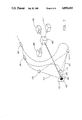
- FIG. 7 is a schematic diagram of another alternate embodiment of the present invention. a laser beam is split into three incident beams.
- Diffraction gratings are used to disperse the frequency components in an incident light beam into a spectrum.
- the exit angle is a function of the beam incident angle and its wavelength.
- the incident beam 20 is simply redirected by the grating 21 into new beams at fixed angles.
- the multiple beams generated are called diffraction orders.
- the zero order 0 is the "normal" reflection, where the angle of incidence equals the angle of reflection.
- the various output diffraction orders are designated ⁇ 1, ⁇ 2, etc.
- the usual procedure of diffraction moire interferometry is to replicate an aluminized diffraction grating 31 onto the specimen 30.
- An incident beam 32 which may be a laser beam, is split into two beams by a beam splitter 33, thereby insuring that the beams 34 and 35 directed to the specimen 30 are mutually coherent.
- Mirror 36 is employed to collimate the beam 34 and mirror 37 collimates the beam 35, directing the beams to the specimen 30.
- Diffraction by the specimen grating 31 produces output beam 38 and output beam 39. Under a load or deformed condition, a pattern of constructive and destructive interference is formed, which appears to the imaging device 40 as fringes of bright and dark.
- the physical cause of fringe production is that loading the specimen 30 distorts the specimen, thereby distorting the grating 31.
- Uniform distortion for example, perpendicular to the grating grooves, will create a grating of lower groove density. This implies that the diffraction orders generated by illuminating the grating 31 will exit the grating 31 at a different angle, obeying the grating equation:
- ⁇ the wavelength of light used to illuminate the grating
- the two first order diffraction beams created by the two incident beams will no longer be aligned and will interfere to produce fringes.
- the resulting fringes will be parallel to each other and to the grating groove direction, with more deformation creating more and finer fringes. If the deformation varies locally over the specimen, then the density and orientation of the fringes will vary similarly.
- the resulting fringe pattern can be analyzed to yield the local extent and nature of the deformation.
- Sensitivity of the diffraction moire interferometer is due to the use of diffraction gratings with very fine spacing (resolution is inversely proportional to the grating spatial frequency).
- Coarse gratings, used commonly with moire deflectometers, are in the order of 20 to 40 lines/mm.
- Fine gratings used for diffraction moire interferometry may range in spatial frequency from 100 lines/mm all the way up to 2000 lines/mm (50,800 lines/inch).
- Incident beam 34 and incident beam 35 must be adjustable with an angular accuracy of one part in 100,000.
- the mirrored system in FIG. 2 accomplishes this using a complex arrangement of beamsplitters, mirrors, path matching arrangements and stable supports for the components.
- the critical beam intersection angle must be exact, and any change in the specimen grating 31 requires that the entire setup process be repeated, often taking several hours even for a very experienced operator.
- FIG. 3 is a schematic diagram of the preferred embodiment of the present invention.
- a laser 53 directs a laser beam to a fiber optic coupler 57.
- the signal is then split by an evanescent wave fiber optic beam splitter 60 (also called a coupler) and the resulting two beams pass respectively through optical fiber 62 to collimating lens 70 and through optical fiber 63 to collimating lens 71.
- Incident beam 74 and incident beam 75 are directed onto the specimen 50 and the diffraction grating 51. Interference patterns are viewed by an imaging device 90.
- the laser 53 is a 10 mw single mode polarized HeNe laser which has a beam diameter of about 0.6 mm.
- a beam expander 55 increases the diameter of the laser output beam to the optimal input diameter of the laser-to-fiber optic coupler 57.
- the intervening beam expander 55 increases the useful power of the HeNa laser 53 by a power of three, enabling use of a less powerful laser, and, like the use of a fast shutter on a camera, making the interferometer less sensitive to vibrations.
- the laser-to-fiber optic coupler 57 serves to focus the output beam of the laser down to the 5 micrometer spot needed to enter the optical fiber 59 efficiently.
- the function of the fiber optic beam splitter 60 is to distribute the beam power equally between two polarization maintaining, single mode optical fibers 62 and 63. In doing so, the device does not distort the beam optical wavefront excessively, and does not disturb the polarization of the output beams 74 and 75.
- the output beam powers are also closely matched to produce good quality data.
- the laser 53 may be mounted remotely, using a fiber optic link (not shown). Mounting the laser 53 remotely will facilitate the use of a more powerful laser, if that is necessary in a particular application.
- the fiber optic system works as well to provide spatial filtering of the laser beam.
- this function is usually provided by an external device consisting of a lens and matching pinhole, whereby the laser beam is focused to a small spot by the lens and passes through the pinhole.
- the fundamental transverse mode of the laser the TEM 00 mode
- the other modes focus to larger spots and are blocked by the pinhole substrate.
- the beam exiting the pinhole has fewer transverse intensity variations, and is said to be "cleaner".
- the single mode fiber 62 has a core only 5 microns in diameter, only the TEM 00 mode is captured by the fiber and transmitted along its length.
- the fiber 62 and laser-to-fiber coupler 57 in combination perform a spatial filtering function.
- the output beam 74 is therefore very clean.
- the fiber 63 which also has a core of 5 microns in diameter, and coupler 57 perform a filtering function and the output beam 75 is very clean.
- the small (5 micron diameter) beam of laser light exiting the optical fiber 62 must be expanded to a useful diameter (often 25 to 50 mm) and then collimated, thereby preventing the beam from spreading further.
- the beam exiting the fiber 62 naturally expands in a cone, so generally no other effort is required to expand the beam until it has expanded sufficiently to cover the lens 70. If the distance from the end of the fiber 62 to the lens 70 is equal to the lens focal length, then the beam exiting the lens 70 will be well collimated. Similarly, if the distance from the end of fiber 63 to the lens 71 is equal to the lens focal length then the beam exiting the lens 71 will be well collimated.
- the lenses 70 and 71 should be well corrected and have multiantireflection coatings throughout.
- Slight adjustments to the collimation can be made with the lens focus mechanism or by moving the end of the fiber 62 relative to the lens 70 or the end of the fiber 63 relative to the lens 71.
- the lens aperture should be wide open in general, since closing down the lens iris simply reduces the beam diameter without dimming the beam.
- the most convenient and inexpensive lenses for collimation are high quality camera lenses, but for very demanding applications specially designed lenses may be preferable.
- an f/5 200 mm focal length lens is suitable for a 50 mm output beam.
- the devices of FIG. 3 are placed in or mounted on a metal enclosure 100, depicted in FIG. 4 to provide a compact portable diffraction moire interferometer.
- the enclosure 100 is made of welded sections of 1/4 inch aluminum plate with two removable lids (not shown) of 1/8 inch aluminum sheet.
- the specific form chosen was designed to provide a highly flexible research instrument. More specialized applications may require fewer adjustments and a simpler or smaller configuration might be appropriate.
- the HeNe laser 53 and its power supply 94 Within the enclosure 100 are the HeNe laser 53 and its power supply 94, the laser beam expander 55, the fiber optic coupler 57, and the fiber optic beamsplitter 60.
- a pair of rack and pinion carriers 81 and 82 and rails 83 and 84 are mounted on the top of the enclosure 100. These are designed to hold the collimating lens assemblies 70 and 71 respectively and to adjust their lateral position relative to each other and to the specimen 50.
- the collimating assemblies 70 and 71 have rotary adjustments 85 and 86 respectively which permit coarse angular positioning in a horizontal plane. This supports a lens mount which permits fine angular adjustments over about ⁇ 3 degrees in both the horizontal and vertical planes.
- a fixed ball (not shown) defines the rear contact point of the enclosure 100 with the table, and a pair of leveling screws (not shown) at the opposite ends of the box near the front provide some adjustment of the orientation of the box relative to the specimen 50.
- An imaging device usually a film or video camera (not shown), can be either internal, attached to the top of the enclosure 100, or external, separately supported by a tripod or other device (not shown).
- the imaging device must be arranged so as to be directed at the specimen grating 51 and so as to permit the ⁇ 1 diffraction orders to enter the device and to be imaged on the recording material (imaging devices which have mechanical movements, such as shutters, should not be mounted on the enclosure 100 to avoid excess vibration).
- the interference patterns may also be observed by direct human vision, with the aid of a device such as an opaque screen, diffusing screen, or magnifying lens placed in the line of sight between the specimen grating and the viewer.
- Alignment of the compact, portable interferometer depicted in FIG. 4 has the purpose of adjusting the angles of incident beam 74 and incident beam 75, and the specimen grating 51 so that the first order diffraction beams exit the grating 51 normal to the grating surface.
- the first diffraction orders from each of the two incident beams 74 and 75 will be perfectly aligned and will interfere to generate an interference pattern.
- the collimating lenses 70 and 71 are adjusted so that the beams 74 and 75 interact in the plane of the specimen 50, and so that the lenses 70 and 71 are equidistant from the midpoint of the rail system 83 and 84.
- Alignment is accomplished in four basic steps, requiring little or no operator experience with optical instruments or the method of diffraction moire interferometry. Of course, caution should be exercised throughout, because eye or skin damage could result due to excessive exposure to the laser beam.
- the intensity of the laser 53 is adjusted and focused on the fiber end of the laser-to-fiber coupler 57. Maximum intensity of the fiber output beam will occur when the laser spot lies on the fiber core.
- the beam intersection angle is set.
- the angle of beams 74 and 75 is constant for each grating groove density and is available in a table look-up format. For example, for a diffraction grating with spatial frequency of 1200 lines/mm, the angle between 74 or 75 and normal will be 49.41 degrees.
- the beam angle is set roughly by adjusting the rotary posts on the rack and pinion carriers 81 and 82 supporting the collimating lenses 70 and 71 respectively. Fine adjustment is completed using the angular adjustments 85 and 86.
- the separation of the collimating lenses 70 and 71 is adjusted. For a given beam angle, the separation between the collimators 70 and 71 determines where the beams intersect, and hence where the specimen 50 will be located. The intersection of beams 74 and 75 is observed on a card, and the collimating lenses 70 and 71 are moved until the intersection lies in the specimen plane. The collimators 70 and 71 should be equidistant from the midpoint of the rail system 83 and 84.
- the specimen grating 51 or an identical reference grating is placed so that it is centered between the collimating lenses 70 and 71 and so that the surface of the grating 51 is perpendicular to the line bisecting the beam angle as well as the viewing direction. This is accomplished by adjusting the angles of beams 74 and 75, and then rotating the grating 51, or the enclosure 100, so that the reflection (i.e. the zero diffraction order) of beam 74 hits the center of the opposite lens 71, and the reflection of beam 75 hits the center of lens 70.
- the interferometer depicted in FIG. 4 accomplishes the object of the present invention, to provide a diffraction moire interferometer which is compact, portable, convenient to use, and requires little user familiarity with the underlying concepts.
- FIG. 5 is a schematic diagram of a four beam system--an alternate embodiment of the present invention which expands the capability of the instrument by permitting the determination of material distortion or strain in both x and y directions simultaneously.
- a normal diffraction grating consists of a series of parallel lines or grooves. Illumination of the grating by two mutually coherent laser beams in the manner described above yields information about distortions perpendicular to the grating grooves. Resolution of the distortions parallel to the grating grooves is accomplished by superimposing two gratings and illuminating the two gratings with two pair of mutually coherent laser beams.
- the output of one laser is split by beamsplitter 260 and the output of a second laser (not shown) is split by the beamsplitter 261.
- Collimating lenses 270 and 271 direct a pair of incident beams 274 and 275 respectively and collimating lenses 272 and 273 direct a pair of incident beams 276 and 277 respectively.
- the lasers may be but need not be matched--for example, one may be an HeNe laser and the other may be a diode laser, as long as each has adequate power and coherence, is compatible with the fiber optics used, and is within the spectral region of a suitable imaging device.
- the incident beams 274, 275, 276 and 277 are directed by the collimating lenses 270, 271, 272 and 273 respectively to two specimen gratings 251 and 252, superimposed so that the grooves of grating 251 are perpendicular to the grooves of grating 252, and vice versa.
- beam separator 293 is used to separate the coincident beams.
- a beam separator might be constructed using long focal length lenses to direct the data beams to one or more mirrors, which in turn would then convey the beams to the imaging devices 290 and 291.
- FIG. 6 depicts a compact, portable instrument which embodies the four beam system.
- Two lasers 353 and 354 draw upon the same power source 359.
- the beam of laser 353 is expanded by expander 355, joined with the fiber optics by a coupler 357, divided into two signals by splitter 360, and focused by collimating lenses 370 and 371 on the specimen grating 351.
- the beam of laser 354 is focused by collimating lenses 372 and 373 on specimen grating 352.
- imaging devices (not shown) aided by a beam separator (not shown) will view the interference patterns representing material distortion of the specimen 350 in both x and y directions.
- a three beam moire interferometry system provides this determination, using three separate beams derived from the same laser so that the three beams are mutually coherent. As illustrated in the schematic diagram of FIG. 7, this is accomplished by using two successive polarization maintaining, single mode fiber optic beamsplitters 460 and 461.
- the first beamsplitter 460 may be variable to permit adjustment of the relative intensities of the beams to compensate for any losses in the fibers or couplers.
- two diffraction gratings 451 and 452 are superimposed so that the grooves of one grating are perpendicular to those of the other.
- the collimating lenses 470, 471 and 472 are respectively placed at the vertices of a right triangle, so that the normal to the specimen passes through the center of the hypotenuse of the right triangle. This arrangement of collimating lenses 470, 471 and 472 accomplishes a 45 degree displacement from x and y directions.
- each interference pattern can be coincident. It is possible to view each interference pattern independently by blocking first beam 474, then beam 475, then beam 476, and recording the fringe pattern generated by each remaining pair of beams. As illustrated in FIG. 7, a beam separator 493 can also be used so that the three interference patterns can be recorded simultaneously.
Abstract
Description
Sin B.sub.m =sin A+m*λ*F
Claims (11)
Priority Applications (3)
| Application Number | Priority Date | Filing Date | Title |
|---|---|---|---|
| US07/197,235 US4850693A (en) | 1988-05-23 | 1988-05-23 | Compact portable diffraction moire interferometer |
| PCT/US1989/002457 WO1989011629A1 (en) | 1988-05-23 | 1989-05-23 | Compact portable diffraction moire interferometer |
| EP89907513A EP0374242A1 (en) | 1988-05-23 | 1989-05-23 | Compact portable diffraction moire interferometer |
Applications Claiming Priority (1)
| Application Number | Priority Date | Filing Date | Title |
|---|---|---|---|
| US07/197,235 US4850693A (en) | 1988-05-23 | 1988-05-23 | Compact portable diffraction moire interferometer |
Publications (1)
| Publication Number | Publication Date |
|---|---|
| US4850693A true US4850693A (en) | 1989-07-25 |
Family
ID=22728573
Family Applications (1)
| Application Number | Title | Priority Date | Filing Date |
|---|---|---|---|
| US07/197,235 Expired - Lifetime US4850693A (en) | 1988-05-23 | 1988-05-23 | Compact portable diffraction moire interferometer |
Country Status (3)
| Country | Link |
|---|---|
| US (1) | US4850693A (en) |
| EP (1) | EP0374242A1 (en) |
| WO (1) | WO1989011629A1 (en) |
Cited By (33)
| Publication number | Priority date | Publication date | Assignee | Title |
|---|---|---|---|---|
| US4984883A (en) * | 1989-07-21 | 1991-01-15 | Joseph Winocur | Translation insensitive keratometer using moire deflectometry |
| US5026154A (en) * | 1989-10-06 | 1991-06-25 | The United States Of America As Represented By The United States Department Of Energy | Multipulsed dynamic moire interferometer |
| WO1992004594A1 (en) * | 1990-08-31 | 1992-03-19 | Commonwealth Scientific And Industrial Research Organisation | Interference microscope |
| US5100227A (en) * | 1989-07-21 | 1992-03-31 | Joseph Winocur | Translation insensitive keratometer using moire deflectometry |
| DE4039972A1 (en) * | 1990-12-14 | 1992-06-17 | Man Technologie Gmbh | Detecting surface deformations by electronic speckle interferometry - coping with two or more deformation directions simultaneously using single light source and symmetrical detection beams |
| US5175601A (en) * | 1991-10-15 | 1992-12-29 | Electro-Optical Information Systems | High-speed 3-D surface measurement surface inspection and reverse-CAD system |
| US5231468A (en) * | 1991-11-06 | 1993-07-27 | Eg&G Idaho, Inc. | Beam shuttering interferometer and method |
| EP0577090A2 (en) * | 1992-06-30 | 1994-01-05 | Canon Kabushiki Kaisha | Optical encoder |
| US5319445A (en) * | 1992-09-08 | 1994-06-07 | Fitts John M | Hidden change distribution grating and use in 3D moire measurement sensors and CMM applications |
| US5349442A (en) * | 1991-09-20 | 1994-09-20 | Eg&G Idaho, Inc. | Hand held phase-shifting diffraction moire interferometer |
| US5481922A (en) * | 1994-05-31 | 1996-01-09 | Washabaugh; Peter D. | Elastic transducer designs incorporating finite length measurement paths |
| US5619332A (en) * | 1995-05-15 | 1997-04-08 | Tracor, Inc. | High spectral resolution fiber optic spectrometer |
| US5633467A (en) * | 1993-06-04 | 1997-05-27 | Pure Technologies Inc. | Apparatus and method for non-destructive testing of structures |
| US5671042A (en) * | 1992-02-18 | 1997-09-23 | Illinois Institute Of Technology | Holomoire strain analyzer |
| US5682236A (en) * | 1993-07-02 | 1997-10-28 | Metrolaser | Remote measurement of near-surface physical properties using optically smart surfaces |
| US5710629A (en) * | 1992-12-10 | 1998-01-20 | Schneider Electric S.A. | Interferometric measuring device forming a spacial interference pattern |
| CN1039157C (en) * | 1994-12-01 | 1998-07-15 | 天津大学 | Intelligent interference cloud testing instrument |
| US5898486A (en) * | 1994-03-25 | 1999-04-27 | International Business Machines Corporation | Portable moire interferometer and corresponding moire interferometric method |
| US6128082A (en) * | 1998-09-18 | 2000-10-03 | Board Of Trustees Operating Michigan State University | Technique and apparatus for performing electronic speckle pattern interferometry |
| US6188482B1 (en) | 1998-09-18 | 2001-02-13 | Board Of Trustees Operating Michigan State University | Apparatus for electronic speckle pattern interferometry |
| US20030015590A1 (en) * | 2001-07-17 | 2003-01-23 | Chen Bo Su | Reflective apparatus and method for optically sensing relative torque employing Moire fringes |
| EP1531318A1 (en) * | 2003-11-17 | 2005-05-18 | University of Liege | Process and apparatus for measuring a 3D shape of an object |
| WO2005049840A2 (en) * | 2003-11-17 | 2005-06-02 | Universite De Liege | Process and apparatus for measuring the three-dimensional shape of an object |
| US6924888B2 (en) * | 2000-11-29 | 2005-08-02 | Steinbichler Optotechnik Gmbh | Process and apparatus for recording the deformation of objects |
| US20070046525A1 (en) * | 2005-02-15 | 2007-03-01 | Holbrook David S | Electromagnetic scanning imager |
| US20070121121A1 (en) * | 2005-10-17 | 2007-05-31 | Robert Wilhelm | Method and apparatus for detecting the deformation of objects |
| US20080075328A1 (en) * | 2006-09-15 | 2008-03-27 | Sciammarella Cesar A | System and method for analyzing displacements and contouring of surfaces |
| US20080278729A1 (en) * | 2007-05-08 | 2008-11-13 | Min Young Kim | Multi-directional projection type moire interferometer and inspection method of using the same |
| US20090195786A1 (en) * | 2008-02-05 | 2009-08-06 | Philippe Gastaldo | Device for inspecting semi-conductor wafers |
| US20100109680A1 (en) * | 2005-02-15 | 2010-05-06 | Walleye Technologies, Inc. | Electromagnetic scanning imager |
| US20100117885A1 (en) * | 2005-02-15 | 2010-05-13 | Holbrook David S | Electromagnetic scanning imager |
| US9632005B1 (en) | 2015-04-20 | 2017-04-25 | Exelis, Inc. | Multi order diffractive devices |
| WO2018209048A1 (en) * | 2017-05-12 | 2018-11-15 | Saudi Arabian Oil Company | Apparatus and method for smart material analysis |
Citations (6)
| Publication number | Priority date | Publication date | Assignee | Title |
|---|---|---|---|---|
| US4432239A (en) * | 1981-12-08 | 1984-02-21 | Bykov Anatoly P | Apparatus for measuring deformation |
| US4459027A (en) * | 1980-11-04 | 1984-07-10 | The State Of Israel, Atomic Energy Commission | Method and equipment for mapping radiation deflection |
| US4474466A (en) * | 1981-03-11 | 1984-10-02 | National Research Development Corporation | Measurement of deformation |
| JPS60177207A (en) * | 1984-02-24 | 1985-09-11 | Toshiba Corp | Strain measuring device |
| US4577940A (en) * | 1984-12-19 | 1986-03-25 | Allied Corporation | Moire microscope |
| US4641972A (en) * | 1984-09-14 | 1987-02-10 | New York Institute Of Technology | Method and apparatus for surface profilometry |
-
1988
- 1988-05-23 US US07/197,235 patent/US4850693A/en not_active Expired - Lifetime
-
1989
- 1989-05-23 EP EP89907513A patent/EP0374242A1/en not_active Withdrawn
- 1989-05-23 WO PCT/US1989/002457 patent/WO1989011629A1/en not_active Application Discontinuation
Patent Citations (6)
| Publication number | Priority date | Publication date | Assignee | Title |
|---|---|---|---|---|
| US4459027A (en) * | 1980-11-04 | 1984-07-10 | The State Of Israel, Atomic Energy Commission | Method and equipment for mapping radiation deflection |
| US4474466A (en) * | 1981-03-11 | 1984-10-02 | National Research Development Corporation | Measurement of deformation |
| US4432239A (en) * | 1981-12-08 | 1984-02-21 | Bykov Anatoly P | Apparatus for measuring deformation |
| JPS60177207A (en) * | 1984-02-24 | 1985-09-11 | Toshiba Corp | Strain measuring device |
| US4641972A (en) * | 1984-09-14 | 1987-02-10 | New York Institute Of Technology | Method and apparatus for surface profilometry |
| US4577940A (en) * | 1984-12-19 | 1986-03-25 | Allied Corporation | Moire microscope |
Non-Patent Citations (4)
| Title |
|---|
| McDonach et al; Optics and Lasers in Engineering, vol. 1, No. 2, pp. 85 105, 12/80. * |
| McDonach et al; Optics and Lasers in Engineering, vol. 1, No. 2, pp. 85-105, 12/80. |
| McKelvie et al; Proc. SPIE, vol. 814, pp. 464 474, 1987. * |
| McKelvie et al; Proc. SPIE, vol. 814, pp. 464-474, 1987. |
Cited By (46)
| Publication number | Priority date | Publication date | Assignee | Title |
|---|---|---|---|---|
| US5100227A (en) * | 1989-07-21 | 1992-03-31 | Joseph Winocur | Translation insensitive keratometer using moire deflectometry |
| US4984883A (en) * | 1989-07-21 | 1991-01-15 | Joseph Winocur | Translation insensitive keratometer using moire deflectometry |
| US5026154A (en) * | 1989-10-06 | 1991-06-25 | The United States Of America As Represented By The United States Department Of Energy | Multipulsed dynamic moire interferometer |
| WO1992004594A1 (en) * | 1990-08-31 | 1992-03-19 | Commonwealth Scientific And Industrial Research Organisation | Interference microscope |
| DE4039972A1 (en) * | 1990-12-14 | 1992-06-17 | Man Technologie Gmbh | Detecting surface deformations by electronic speckle interferometry - coping with two or more deformation directions simultaneously using single light source and symmetrical detection beams |
| US5349442A (en) * | 1991-09-20 | 1994-09-20 | Eg&G Idaho, Inc. | Hand held phase-shifting diffraction moire interferometer |
| US5175601A (en) * | 1991-10-15 | 1992-12-29 | Electro-Optical Information Systems | High-speed 3-D surface measurement surface inspection and reverse-CAD system |
| US5231468A (en) * | 1991-11-06 | 1993-07-27 | Eg&G Idaho, Inc. | Beam shuttering interferometer and method |
| US5671042A (en) * | 1992-02-18 | 1997-09-23 | Illinois Institute Of Technology | Holomoire strain analyzer |
| US5359193A (en) * | 1992-06-30 | 1994-10-25 | Canon Kabushiki Kaisha | Talbot's interference type optical encoder |
| EP0577090A2 (en) * | 1992-06-30 | 1994-01-05 | Canon Kabushiki Kaisha | Optical encoder |
| EP0577090A3 (en) * | 1992-06-30 | 1994-03-23 | Canon Kk | |
| US5319445A (en) * | 1992-09-08 | 1994-06-07 | Fitts John M | Hidden change distribution grating and use in 3D moire measurement sensors and CMM applications |
| US5710629A (en) * | 1992-12-10 | 1998-01-20 | Schneider Electric S.A. | Interferometric measuring device forming a spacial interference pattern |
| US5633467A (en) * | 1993-06-04 | 1997-05-27 | Pure Technologies Inc. | Apparatus and method for non-destructive testing of structures |
| US5682236A (en) * | 1993-07-02 | 1997-10-28 | Metrolaser | Remote measurement of near-surface physical properties using optically smart surfaces |
| US5898486A (en) * | 1994-03-25 | 1999-04-27 | International Business Machines Corporation | Portable moire interferometer and corresponding moire interferometric method |
| US5481922A (en) * | 1994-05-31 | 1996-01-09 | Washabaugh; Peter D. | Elastic transducer designs incorporating finite length measurement paths |
| CN1039157C (en) * | 1994-12-01 | 1998-07-15 | 天津大学 | Intelligent interference cloud testing instrument |
| US5619332A (en) * | 1995-05-15 | 1997-04-08 | Tracor, Inc. | High spectral resolution fiber optic spectrometer |
| US6128082A (en) * | 1998-09-18 | 2000-10-03 | Board Of Trustees Operating Michigan State University | Technique and apparatus for performing electronic speckle pattern interferometry |
| US6188482B1 (en) | 1998-09-18 | 2001-02-13 | Board Of Trustees Operating Michigan State University | Apparatus for electronic speckle pattern interferometry |
| US6924888B2 (en) * | 2000-11-29 | 2005-08-02 | Steinbichler Optotechnik Gmbh | Process and apparatus for recording the deformation of objects |
| US20030015590A1 (en) * | 2001-07-17 | 2003-01-23 | Chen Bo Su | Reflective apparatus and method for optically sensing relative torque employing Moire fringes |
| US6817528B2 (en) * | 2001-07-17 | 2004-11-16 | Honeywell International Inc. | Reflective apparatus and method for optically sensing relative torque employing Moirè fringes |
| EP1531318A1 (en) * | 2003-11-17 | 2005-05-18 | University of Liege | Process and apparatus for measuring a 3D shape of an object |
| WO2005049840A2 (en) * | 2003-11-17 | 2005-06-02 | Universite De Liege | Process and apparatus for measuring the three-dimensional shape of an object |
| WO2005049840A3 (en) * | 2003-11-17 | 2005-07-21 | Univ Liege | Process and apparatus for measuring the three-dimensional shape of an object |
| US8253619B2 (en) | 2005-02-15 | 2012-08-28 | Techtronic Power Tools Technology Limited | Electromagnetic scanning imager |
| US8593157B2 (en) | 2005-02-15 | 2013-11-26 | Walleye Technologies, Inc. | Electromagnetic scanning imager |
| US20070046525A1 (en) * | 2005-02-15 | 2007-03-01 | Holbrook David S | Electromagnetic scanning imager |
| US7626400B2 (en) | 2005-02-15 | 2009-12-01 | Walleye Technologies, Inc. | Electromagnetic scanning imager |
| US20100109680A1 (en) * | 2005-02-15 | 2010-05-06 | Walleye Technologies, Inc. | Electromagnetic scanning imager |
| US20100117885A1 (en) * | 2005-02-15 | 2010-05-13 | Holbrook David S | Electromagnetic scanning imager |
| US7860297B2 (en) * | 2005-10-17 | 2010-12-28 | Steinbichler Optotechnik Gmbh | Method and apparatus for detecting the deformation of objects |
| US20070121121A1 (en) * | 2005-10-17 | 2007-05-31 | Robert Wilhelm | Method and apparatus for detecting the deformation of objects |
| US8054471B2 (en) | 2006-09-15 | 2011-11-08 | Sciammarella Cesar A | System and method for analyzing displacements and contouring of surfaces |
| US20080075328A1 (en) * | 2006-09-15 | 2008-03-27 | Sciammarella Cesar A | System and method for analyzing displacements and contouring of surfaces |
| US7894077B2 (en) * | 2007-05-08 | 2011-02-22 | Koh Young Technology Inc. | Multi-directional projection type moire interferometer and inspection method of using the same |
| US20080278729A1 (en) * | 2007-05-08 | 2008-11-13 | Min Young Kim | Multi-directional projection type moire interferometer and inspection method of using the same |
| US20090195786A1 (en) * | 2008-02-05 | 2009-08-06 | Philippe Gastaldo | Device for inspecting semi-conductor wafers |
| US9632005B1 (en) | 2015-04-20 | 2017-04-25 | Exelis, Inc. | Multi order diffractive devices |
| WO2018209048A1 (en) * | 2017-05-12 | 2018-11-15 | Saudi Arabian Oil Company | Apparatus and method for smart material analysis |
| US10401155B2 (en) | 2017-05-12 | 2019-09-03 | Saudi Arabian Oil Company | Apparatus and method for smart material analysis |
| CN110603432A (en) * | 2017-05-12 | 2019-12-20 | 沙特阿拉伯石油公司 | Apparatus and method for smart material analysis |
| US10895447B2 (en) | 2017-05-12 | 2021-01-19 | Saudi Arabian Oil Company | Apparatus for smart material analysis |
Also Published As
| Publication number | Publication date |
|---|---|
| WO1989011629A1 (en) | 1989-11-30 |
| EP0374242A1 (en) | 1990-06-27 |
Similar Documents
| Publication | Publication Date | Title |
|---|---|---|
| US4850693A (en) | Compact portable diffraction moire interferometer | |
| KR100225923B1 (en) | Phase shifting diffraction interferometer | |
| US4869593A (en) | Interferometric surface profiler | |
| US4948253A (en) | Interferometric surface profiler for spherical surfaces | |
| US6188482B1 (en) | Apparatus for electronic speckle pattern interferometry | |
| US5493398A (en) | Device for observing test-piece surfaces by the speckle-shearing-method for the measurement of deformations | |
| US6806965B2 (en) | Wavefront and intensity analyzer for collimated beams | |
| PT736759E (en) | WAVE FRONT DETECTOR WITH MICRO-MIRROR FOR SELF-REFERENCE AND ITS ALIGNMENT | |
| JPS59500488A (en) | Optical processing method and device using holography | |
| US3447874A (en) | Apparatus for testing lenses and method | |
| JPH0224504A (en) | Interferometer for measuring shape of aspheric surface utilizing computer hologram | |
| JPH0324432A (en) | Optical instrument for phase detection inspection of optical system, particularly spectacle lens | |
| US4474466A (en) | Measurement of deformation | |
| US6704112B1 (en) | Application of the phase shifting diffraction interferometer for measuring convex mirrors and negative lenses | |
| US4747688A (en) | Fiber optic coherence meter | |
| JPH0769219B2 (en) | Interference fringe analysis method and apparatus therefor | |
| CN1039745C (en) | Real-time one step double-wavelength holographic interference checking device | |
| US4347000A (en) | Interferometric system | |
| Deason et al. | A compact portable diffraction moiré interferometer | |
| JP2621792B2 (en) | Method and apparatus for measuring spatial coherence | |
| SU848999A1 (en) | Interferometer for checking lens and mirror aberration changes in the process of their mounting position | |
| JPS60211306A (en) | Adjusting method of optical system of fringe scan shearing interference measuring instrument | |
| JP3410800B2 (en) | Vibration resistant interferometer | |
| Page | Interferometry | |
| US4733964A (en) | Device for joining light waves |
Legal Events
| Date | Code | Title | Description |
|---|---|---|---|
| AS | Assignment |
Owner name: UNITED STATES OF AMERICA, THE, AS REPRESENTED BY T Free format text: ASSIGNMENT OF ASSIGNORS INTEREST.;ASSIGNORS:DEASON, VANCE A.;WARD, MICHAEL B.;REEL/FRAME:004930/0169 Effective date: 19880517 |
|
| STCF | Information on status: patent grant |
Free format text: PATENTED CASE |
|
| FEPP | Fee payment procedure |
Free format text: PAYOR NUMBER ASSIGNED (ORIGINAL EVENT CODE: ASPN); ENTITY STATUS OF PATENT OWNER: LARGE ENTITY |
|
| FPAY | Fee payment |
Year of fee payment: 4 |
|
| AS | Assignment |
Owner name: EG&G IDAHO, INC., IDAHO Free format text: ASSIGNMENT OF ASSIGNORS INTEREST.;ASSIGNORS:DEASON, VANCE A.;WARD, MICHAEL B.;REEL/FRAME:006442/0476 Effective date: 19930204 |
|
| FPAY | Fee payment |
Year of fee payment: 8 |
|
| AS | Assignment |
Owner name: LOCKHEED MARTIN IDAHO TECHNOLOGIES, IDAHO Free format text: ASSIGNMENT OF ASSIGNORS INTEREST;ASSIGNOR:EG&G IDAHO, INC.;REEL/FRAME:010226/0278 Effective date: 19940921 |
|
| AS | Assignment |
Owner name: BECHTEL BXWT IDAHO, LLC, IDAHO Free format text: ASSIGNMENT OF ASSIGNORS INTEREST;ASSIGNOR:LOCKHEED MARTIN IDAHO TECHNOLOGIES COMPANY;REEL/FRAME:010579/0988 Effective date: 19990928 |
|
| REMI | Maintenance fee reminder mailed | ||
| FPAY | Fee payment |
Year of fee payment: 12 |
|
| SULP | Surcharge for late payment |
Year of fee payment: 11 |
|
| AS | Assignment |
Owner name: BATTELLE ENERGY ALLIANCE, LLC, IDAHO Free format text: ASSIGNMENT OF ASSIGNORS INTEREST;ASSIGNOR:BECHTEL BWXT IDAHO, LLC;REEL/FRAME:016226/0765 Effective date: 20050201 Owner name: BATTELLE ENERGY ALLIANCE, LLC,IDAHO Free format text: ASSIGNMENT OF ASSIGNORS INTEREST;ASSIGNOR:BECHTEL BWXT IDAHO, LLC;REEL/FRAME:016226/0765 Effective date: 20050201 |