US4850162A - Access floor system - Google Patents
Access floor system Download PDFInfo
- Publication number
- US4850162A US4850162A US07/224,103 US22410388A US4850162A US 4850162 A US4850162 A US 4850162A US 22410388 A US22410388 A US 22410388A US 4850162 A US4850162 A US 4850162A
- Authority
- US
- United States
- Prior art keywords
- pedestals
- duct
- duct element
- access floor
- floor arrangement
- Prior art date
- Legal status (The legal status is an assumption and is not a legal conclusion. Google has not performed a legal analysis and makes no representation as to the accuracy of the status listed.)
- Expired - Fee Related
Links
Images


Classifications
-
- E—FIXED CONSTRUCTIONS
- E04—BUILDING
- E04F—FINISHING WORK ON BUILDINGS, e.g. STAIRS, FLOORS
- E04F15/00—Flooring
- E04F15/02—Flooring or floor layers composed of a number of similar elements
- E04F15/024—Sectional false floors, e.g. computer floors
- E04F15/02447—Supporting structures
- E04F15/02458—Framework supporting the panels
-
- H—ELECTRICITY
- H02—GENERATION; CONVERSION OR DISTRIBUTION OF ELECTRIC POWER
- H02G—INSTALLATION OF ELECTRIC CABLES OR LINES, OR OF COMBINED OPTICAL AND ELECTRIC CABLES OR LINES
- H02G3/00—Installations of electric cables or lines or protective tubing therefor in or on buildings, equivalent structures or vehicles
- H02G3/28—Installations of cables, lines, or separate protective tubing therefor in conduits or ducts pre-established in walls, ceilings or floors
- H02G3/283—Installations of cables, lines, or separate protective tubing therefor in conduits or ducts pre-established in walls, ceilings or floors in floors
- H02G3/285—Installations of cables, lines, or separate protective tubing therefor in conduits or ducts pre-established in walls, ceilings or floors in floors in modular floors, e.g. access floors
-
- F—MECHANICAL ENGINEERING; LIGHTING; HEATING; WEAPONS; BLASTING
- F24—HEATING; RANGES; VENTILATING
- F24F—AIR-CONDITIONING; AIR-HUMIDIFICATION; VENTILATION; USE OF AIR CURRENTS FOR SCREENING
- F24F2221/00—Details or features not otherwise provided for
- F24F2221/40—HVAC with raised floors
Definitions
- the present invention relates to access floor systems, particularly to those used in elevated floor systems wherein the floor is raised above a supporting subfloor, having high and low voltage wiring distributed between the elevated floor and the subfloor in order to service equipment at various locations on the floor.
- Elevated floor assemblies also called full access floor assemblies, comprising a raised floor supported a spaced distance above a permanent or otherwise supporting subfloor, are in general use in contemporary buildings, particularly in areas used for housing computers and computer-related systems.
- Computers, printers, and other peripherals, etc. are typically interconnected by cables, pipes, air ducts, and the like for the purpose of powering and coordinating the various units and maintaining each unit at its required operating temperature.
- the elevated floor assembly enables these interconnections to be routed and channeled in the space defined by the raised floor and the supporting subfloor below.
- the standard elevated floor structure consists of floor panels, such as those disclosed in U.S. Pat. No. 4,656,795, which are supported above a subfloor, generally by a plurality of pedestals, such as those described in U.S. Pat. Nos. 4,558,544 and 3,398,933.
- the present invention comprises an elevated floor having a duct element which significantly reduces the line tangling problems of prior elevated floor systems and permits various lines to be segregated as needed.
- the duct element comprises a pair of generally parallel cells joined together in a spaced-apart relationship. Each element is secured to a row of a plurality of pedestals, such that a cell is disposed on each side of the row of pedestals.
- the interconnecting electrical cables, hookup lines, etc. are run through the cells, thereby significantly reducing the tangled, random line network of prior systems.
- Each cell may be used for running compatible wiring, segregating that wiring from that in the other cell.
- the duct element assists the pedestals in supporting the elevated floor, while in another preferred embodiment, the duct elements are disposed a spaced distance below the elevated floor and render no support therefor.
- feeder ducts extend transversely of the duct elements and communicate with the cells.
- FIG. 1 is an isometric illustration of a preferred duct element of the present invention.
- FIG. 1a is an isometric view of an alternative embodiment of a duct element of the present invention.
- FIG. 2 is a plan view schematically illustrating an elevated floor system showing pedestals and a pair of the duct elements of the present invention cooperating with a feeder duct.
- FIG. 3 is a side view of a duct element of the present invention.
- FIG. 4 is a cross-sectional view, taken along the line 4--4 of FIG. 2, showing a preferred embodiment of the present invention.
- FIG. 5 is a cross-sectional view, similar to FIG. 4, showing another preferred embodiment of the present invention.
- FIG. 6 is an isometric view of a preferred duct element of the present invention being used in cooperation with a feeder duct.
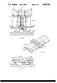
- FIG. 7 is a cross-sectional view taken along the line 7--7 of FIG. 6.
- FIG. 8 is an elevation view in partial cross section of a preferred embodiment of the present invention, illustrating a method of supporting the feeder duct.
- FIG. 9 is an isometric view of an optional hold-down clip for use with a preferred embodiment of the present invention.
- FIG. 10 is a partial cross sectional view of a preferred embodiment of the present invention showing the use of the optional hold-down clip of FIG. 9.
- FIG. 1 illustrates a preferred embodiment of a duct element used in practicing the present invention.
- the duct element generally 10 presents a pair of spaced-apart, generally parallel cells 11 having hollow interiors 13, through which wiring (not shown) may be passed, and maintained in a relatively disentangled state.
- the duct element 10 may be formed from upper and lower corrugated members 14, 15 having contiguous portions, such as, central spacer portions 12 and outwardly extending ribs 16.
- the members 14, 15 may be spot welded or otherwise secured together along the contiguous portions 12, 16.
- the spacer portion 12 has a plurality of pedestal openings 17 which allow the duct element 10 to be mounted on plural pedestals 18 of a row of pedestals, as will hereinafter be described.
- the pedestals 18 are arranged in an array of rows R and columns C, the spacing for which is generally dictated by the horizontal dimensions of the raised access floor panels which are supported on these pedestals, the loading requirements for the particular elevated floor and the loading capacity of the individual pedestals used.
- the pedestals 18 rest on and preferably are secured to a support surface 29, such as a concrete subfloor. As shown in FIGS.
- the duct elements 10 straddle a row of pedestals 18 such that one of the cells 11 is disposed on each side of the row of pedestals 18 that is, each cell 11 is laterally offset from the pedestals of the row of pedestals 18.
- more than one duct element 10 may be used, and a second duct element may be spaced from the first duct element and similarly secured to a second row of pedestals 18, such that one of the cells is disposed on each side of the second row of pedestals, that is, each of the cells 11 is laterally offset from the pedestals of the second row.
- the duct element 10 may have at either end a recessed portion 19, which may be dimensioned and shaped to receive a lap strip 20, used to secure adjoining sections of the duct elements 10 together as shown.
- the adjoining sections may be joined in a male end/female end-type fashion.
- FIG. 3 illustrates a side elevation of a section of the duct element 10.
- the cells 11 of the duct element 10 generally include in the outboard vertical webs 21 of the cell, a plurality of knock-outs 22, for egressing the various wires running through the cells 11 in order to access the equipment on the elevated floor.
- These knock-outs 22 generally provide communication between each of the cells and the plenum space S (FIG. 4) between the access floor panels 24 and the supporting surface 29.
- FIG. 4 illustrates a preferred method of mounting a duct element 10 on a pedestal 18, which has a base 18a resting on a subfloor 29, such as a concrete slab.
- each cell 11 of the duct element 10 has an upper surface 11a which assists in supporting the elevated floor, generally 23.
- a relatively small portion of the cell resides above the top of the pedestal 18, while a relatively major portion of the cell resides below the top of the pedestal 18.
- the elevated floor 23 is comprised of multiple access floor panels 24.
- the duct element 10 is secured to the pedestal 18 by sliding the pedestal opening 17 in the spacer portion 12 down over the pedestal column 26 until the spacer portion 12 comes to rest on an adjustable collar 25 on the pedestal 18.
- the adjustable collar 25 may be a pipe with enlarged end portions which is slidably disposed on the pedestal column 26.
- the pedestal column 26 may be threaded as shown, in which case a pedestal adjusting nut 27 on which the collar 25 rests may be used to adjust the collar 25 vertically as required, in order to position the cells 11 in supporting engagement with the access floor 23 as illustrated.
- the duct element may be secured in place, as with a top locking nut 28, which is threaded down into locking engagement with the spacer portion 12.
- each of the cells 11 of the duct element 10 is disposed on opposite sides of the particular row of pedestals 18 cooperating with the duct element.
- the duct element of the FIG. 4 embodiment acts in a dual capacity, as a combined stringer for supporting in part the elevated floor 23, and as a dual cell arrangement for containing and segregating various wires and other interconnections running below the floor 23.
- FIGS. 2 and 4 and assuming this Figure represents a plan view of a floor system using the embodiment illustrated in FIG. 4, it is evident that the duct element 10 supports those portions of the elevated floor 23 which are directly over the duct elements 10. However, areas of the floor 23 which are not directly over the duct elements 10 are supported by the pedestals 18.
- certain of the floor panels 24 are supported in part by the pedestals 18 and in part by the duct element 10.
- FIG. 5 An alternative preferred embodiment of the present invention is illustrated in FIG. 5.
- the access floor panels 24 are supported directly by the pedestals 18 rather than by the cells 11, and the duct element 10 resides entirely below the top of the pedestal 18.
- the adjustable collar 25 includes an upper platform 30 which supports the access floor panels as shown.
- the access floor panels may be secured to the upper platform 30 by fasteners 31, such as hold-down screws, which are placed at all four intersecting corners of the panels 24, which corners are supported by the pedestal 18. In such a configuration, there generally exists a space 32 between the panels 24 and the top surface 11a of the cells 11.
- the duct element 10 is formed from an upper corrugated member 14a and a flat lower member 43 which is coextensive in width and length with the upper member 14a.
- the upper member 14a of the cells 11 has flared ribs 16 which along with the spacer portion 12 may be attached to the flat lower member 43 as earlier described.
- the cells 11 and upper platform 30 are simultaneously adjusted vertically by turning the nut 27 in the appropriate direction on the threaded pedestal column 26.
- either of the FIG. 4 or FIG. 5 embodiments of the present invention may be used in cooperation with a feeder duct 33 which extends transversely of and beneath the duct element 10, and which overlies the subfloor or support surface 29.
- the feeder duct 33 may rest on the supporting surface 29, and communicates with the cells 11. If the feeder duct rests on the supporting surface 29, it may be necessary to use shims (not shown) under the feeder duct 33 if the supporting surface is irregular or out of plane.
- the duct elements 10 may be attached to the feeder duct in any practical manner, such as by use of L-shaped clips 44 (FIG. 7) which are welded or rivited at the intersecting corners of the duct element 10 and feeder duct 33.
- the feeder duct 33 is segregated into two compartments, 34.
- One compartment 34 may be used for high voltage, such as power wiring, and accesses one of the cells 11, which cell is used for a corresponding purpose, and the other compartment 34 may be used for low voltage service, such as telephone and computer wiring, and likewise accesses the other cell 11, which is used for a corresponding purpose.
- the feeder duct 33 preferably has removable covers 35, which may be removed to access the compartments 34 therein. Also, the feeder duct 33 preferably has a divider 36 which segregates the interior of the feeder duct 33 into the separate compartments 34.
- FIG. 7 illustrates the duct element 10 at a point of intersection with the feeder duct 33. As shown, the cells 11 rest on the feeder duct 33. In this illustration (FIG. 7), one of the cells 11 is accessed by the electrical wires, and the other of the cells 11, which is not seen, would be accessed by the telephone/computer wires.
- FIG. 8 illustrates a method of supporting the feeder duct 33 on the pedestals 18 in situations where the height of the floor 23 is equal to or greater than seven inches.
- the feeder duct 33 may be supported by support stringers 37, which span between two adjacent pedestals 18 and are secured thereto, as by pointed set screws 38.
- the set screws are loosened and the stringer 37, which is slidably received by the pedestal 18, is slid up or down on the pedestal as desired to the required position and the set screws are tightened.
- the duct elements would rest on the feeder ducts as earlier described.
- FIGS. 9 and 10 illustrate an optional hold-down clip for use in providing further stability to the system illustrated in FIG. 4, without the need for stringers.
- the hold-down clip generally 39, comprises a saddle-shaped member having a pair of attachment flanges 40, which permit the clip 39 to be attached to the spacer portion 12 as illustrated in FIG. 10.
- the attachment may be by any means, such as spot welding, or field installed break stem rivets.
- the clip 39 has a top wall 41 which, when the clip is positioned on the spacer portion 12, is disposed at substantially the same height as the top surface 11a of the cells 11.
- the top wall 41 preferably includes a plurality of threaded holes 42 into which the fasteners, or panel hold down screws 31 are threaded in order to secure the access floor panels 24 to the clip 38, as shown in FIG. 10.
Abstract
Description
Claims (19)
Priority Applications (3)
| Application Number | Priority Date | Filing Date | Title |
|---|---|---|---|
| US07/224,103 US4850162A (en) | 1988-07-26 | 1988-07-26 | Access floor system |
| ES8900615A ES2015375A6 (en) | 1988-07-26 | 1989-02-21 | Access floor system |
| PT91109A PT91109A (en) | 1988-07-26 | 1989-07-10 | PAVEMENT SYSTEM WITH ACCESS |
Applications Claiming Priority (1)
| Application Number | Priority Date | Filing Date | Title |
|---|---|---|---|
| US07/224,103 US4850162A (en) | 1988-07-26 | 1988-07-26 | Access floor system |
Publications (1)
| Publication Number | Publication Date |
|---|---|
| US4850162A true US4850162A (en) | 1989-07-25 |
Family
ID=22839292
Family Applications (1)
| Application Number | Title | Priority Date | Filing Date |
|---|---|---|---|
| US07/224,103 Expired - Fee Related US4850162A (en) | 1988-07-26 | 1988-07-26 | Access floor system |
Country Status (3)
| Country | Link |
|---|---|
| US (1) | US4850162A (en) |
| ES (1) | ES2015375A6 (en) |
| PT (1) | PT91109A (en) |
Cited By (38)
| Publication number | Priority date | Publication date | Assignee | Title |
|---|---|---|---|---|
| US5341614A (en) * | 1992-12-23 | 1994-08-30 | Mirai Industries Co., Ltd. | Floor system for laying cables and pipes underneath the floor |
| US5465534A (en) * | 1994-05-26 | 1995-11-14 | Equipto | Flooring substructure |
| US5477649A (en) * | 1993-04-30 | 1995-12-26 | Airtite Contractors Inc. | Raised floor cable trough system |
| US5483776A (en) * | 1993-05-18 | 1996-01-16 | Steelcase, Inc. | Utility floor construction |
| US5546717A (en) * | 1994-04-20 | 1996-08-20 | Walker Systems, Inc. | Access floor trench raceway |
| US5548932A (en) * | 1994-11-08 | 1996-08-27 | Maxcess Technologies, Inc. | Adjustable cable tray support system |
| EP0758040A2 (en) * | 1995-08-08 | 1997-02-12 | Mensch AG Gipsergeschäft | Sectional false floor |
| US5613330A (en) * | 1994-12-27 | 1997-03-25 | Euroshield Oy | Support pillar system for a magnetically-shielded room |
| WO1997042692A1 (en) * | 1996-05-08 | 1997-11-13 | T.T.H. Ltd. | Cable management systems |
| US5761855A (en) * | 1996-06-28 | 1998-06-09 | Vanguard Semiconductor Corporation | Structure and method of implementing a supplementary column for supporting a raised floor |
| US5953870A (en) * | 1997-09-11 | 1999-09-21 | Jette; Roger | Raised floor system and cable support apparatus |
| US6347493B1 (en) | 1997-09-11 | 2002-02-19 | Roger Jette | Raised floor system and support apparatus |
| US6463704B1 (en) | 1999-11-05 | 2002-10-15 | Roger Jette | Cable support apparatus for a raised floor system |
| US20030089049A1 (en) * | 2001-11-13 | 2003-05-15 | Maxcess Technologies, Inc. | Resilient pedestal head for a raised access floor system |
| US6637165B2 (en) | 1997-09-11 | 2003-10-28 | Roger Jette | Raised floor system and support apparatus |
| US20030213191A1 (en) * | 2001-07-30 | 2003-11-20 | Roger Jette | Cable support apparatus for a raised floor system |
| US6669163B2 (en) * | 2000-01-20 | 2003-12-30 | Universal Support Systems Llc | Support apparatus and grounded equipment frame |
| US6672022B2 (en) | 2000-05-31 | 2004-01-06 | George E. Simmons | Cable tray support system |
| US20040055232A1 (en) * | 1997-09-11 | 2004-03-25 | Roger Jette | Raised floor system and support apparatus |
| US20050005547A1 (en) * | 2003-07-11 | 2005-01-13 | Bruce Mead | Top levelled pedestal |
| US7032614B2 (en) | 2000-11-03 | 2006-04-25 | Applied Materials, Inc. | Facilities connection box for pre-facilitation of wafer fabrication equipment |
| US7063301B2 (en) | 2000-11-03 | 2006-06-20 | Applied Materials, Inc. | Facilities connection bucket for pre-facilitation of wafer fabrication equipment |
| US20070082588A1 (en) * | 2005-09-27 | 2007-04-12 | De Vries Nicholas | Methods and apparatus for coupling semiconductor device manufacturing equipment to the facilities of a manufacturing location |
| US20080066401A1 (en) * | 2006-09-14 | 2008-03-20 | Roger Jette | Suspended cable support system |
| US7373759B1 (en) | 2000-05-31 | 2008-05-20 | Simmons George E | Cable tray support assembly |
| WO2008102395A1 (en) * | 2007-02-21 | 2008-08-28 | Intec S.P.A | A modular plate for forming a horizontal partition for dividing the cavity between a load bearing sill and a raised floor |
| EP1936766A3 (en) * | 1997-09-11 | 2008-10-15 | Roger Jette | Raised floor system and support apparatus |
| US20100062703A1 (en) * | 2007-06-26 | 2010-03-11 | Toyota Shatai Kabushiki Kaisha | Duct installation structure |
| US20100281790A1 (en) * | 2009-05-07 | 2010-11-11 | Philip Burgess | Adjustable Leveling Pedestal |
| US20130320161A1 (en) * | 2012-06-04 | 2013-12-05 | Hilti Aktiengesellschaft | Support foot for applying and distributing forces to a pressure-sensitive substrate as well as a stand system having such a support foot |
| ITMI20122029A1 (en) * | 2012-11-29 | 2014-05-30 | Roberto Messana | PLENUM WITH MODULAR ELEMENTS FOR AIR-CONDITIONING SYSTEMS, IN AN RAISED FLOOR STRUCTURE. |
| WO2014096190A1 (en) * | 2012-12-21 | 2014-06-26 | Tegometall International Ag | Hook part |
| US20150101275A1 (en) * | 2013-10-15 | 2015-04-16 | Rad Technology Medical Systems Llc | Radiation vault module with adjustable base frame |
| EP2889222A1 (en) * | 2013-12-31 | 2015-07-01 | Airbus Operations (S.A.S) | Temporary floor for an aircraft cabin, used during the construction of the aircraft, and slab making up said floor |
| US20170051526A1 (en) * | 2015-08-19 | 2017-02-23 | biljax inc. | Engineered Floor and Scaffold Systems |
| EP3747313A1 (en) * | 2019-06-05 | 2020-12-09 | Rol Ergo AB | Method of manufacturing a base plate member for a table and a product thereof |
| USRE49817E1 (en) * | 2016-07-01 | 2024-01-30 | O'keeffe's, Inc. | Mechanism for supporting and positioning a glass floor unit |
| US11959300B2 (en) | 2020-09-02 | 2024-04-16 | Bil-Jax, Inc. | Floor structure system and method of use |
Citations (11)
| Publication number | Priority date | Publication date | Assignee | Title |
|---|---|---|---|---|
| DE1002517B (en) * | 1952-04-09 | 1957-02-14 | Kloeckner Humboldt Deutz Ag | Welded junction connection for trusses made of tubular profiles |
| US2870623A (en) * | 1957-09-24 | 1959-01-27 | Victor S Murray | Supported concrete floor and conduits |
| US2975559A (en) * | 1957-02-12 | 1961-03-21 | Robertson Co H H | Wire distributing cellular metal floor |
| FR1306680A (en) * | 1961-09-05 | 1962-10-19 | Improvements made to sets such as heated floors | |
| CA676751A (en) * | 1963-12-24 | S. Murray Victor | Multi-cell underfloor duct and junction box therefor | |
| US3316680A (en) * | 1964-02-11 | 1967-05-02 | Jerome R Chrastek | Floor structure |
| US3398933A (en) * | 1966-06-29 | 1968-08-27 | Victor G. Haroldson | Adjustable pedestal for elevated flooring |
| US3924370A (en) * | 1974-07-24 | 1975-12-09 | Bell Telephone Labor Inc | Raised floor with clamped panel support |
| US4016357A (en) * | 1975-07-18 | 1977-04-05 | Burroughs Corporation | Floor structure for the environment of a modular computer system |
| US4558544A (en) * | 1983-03-30 | 1985-12-17 | H. H. Robertson Company | Adjustable pedestal for elevated floors |
| US4656795A (en) * | 1983-06-10 | 1987-04-14 | H. H. Robertson Company | Floor panel for elevated floor assembly |
-
1988
- 1988-07-26 US US07/224,103 patent/US4850162A/en not_active Expired - Fee Related
-
1989
- 1989-02-21 ES ES8900615A patent/ES2015375A6/en not_active Expired - Fee Related
- 1989-07-10 PT PT91109A patent/PT91109A/en not_active Application Discontinuation
Patent Citations (11)
| Publication number | Priority date | Publication date | Assignee | Title |
|---|---|---|---|---|
| CA676751A (en) * | 1963-12-24 | S. Murray Victor | Multi-cell underfloor duct and junction box therefor | |
| DE1002517B (en) * | 1952-04-09 | 1957-02-14 | Kloeckner Humboldt Deutz Ag | Welded junction connection for trusses made of tubular profiles |
| US2975559A (en) * | 1957-02-12 | 1961-03-21 | Robertson Co H H | Wire distributing cellular metal floor |
| US2870623A (en) * | 1957-09-24 | 1959-01-27 | Victor S Murray | Supported concrete floor and conduits |
| FR1306680A (en) * | 1961-09-05 | 1962-10-19 | Improvements made to sets such as heated floors | |
| US3316680A (en) * | 1964-02-11 | 1967-05-02 | Jerome R Chrastek | Floor structure |
| US3398933A (en) * | 1966-06-29 | 1968-08-27 | Victor G. Haroldson | Adjustable pedestal for elevated flooring |
| US3924370A (en) * | 1974-07-24 | 1975-12-09 | Bell Telephone Labor Inc | Raised floor with clamped panel support |
| US4016357A (en) * | 1975-07-18 | 1977-04-05 | Burroughs Corporation | Floor structure for the environment of a modular computer system |
| US4558544A (en) * | 1983-03-30 | 1985-12-17 | H. H. Robertson Company | Adjustable pedestal for elevated floors |
| US4656795A (en) * | 1983-06-10 | 1987-04-14 | H. H. Robertson Company | Floor panel for elevated floor assembly |
Cited By (53)
| Publication number | Priority date | Publication date | Assignee | Title |
|---|---|---|---|---|
| US5341614A (en) * | 1992-12-23 | 1994-08-30 | Mirai Industries Co., Ltd. | Floor system for laying cables and pipes underneath the floor |
| US5477649A (en) * | 1993-04-30 | 1995-12-26 | Airtite Contractors Inc. | Raised floor cable trough system |
| US5483776A (en) * | 1993-05-18 | 1996-01-16 | Steelcase, Inc. | Utility floor construction |
| US5546717A (en) * | 1994-04-20 | 1996-08-20 | Walker Systems, Inc. | Access floor trench raceway |
| US5465534A (en) * | 1994-05-26 | 1995-11-14 | Equipto | Flooring substructure |
| US5548932A (en) * | 1994-11-08 | 1996-08-27 | Maxcess Technologies, Inc. | Adjustable cable tray support system |
| US5613330A (en) * | 1994-12-27 | 1997-03-25 | Euroshield Oy | Support pillar system for a magnetically-shielded room |
| EP0758040A3 (en) * | 1995-08-08 | 1998-09-30 | Mensch AG Gipsergeschäft | Sectional false floor |
| EP0758040A2 (en) * | 1995-08-08 | 1997-02-12 | Mensch AG Gipsergeschäft | Sectional false floor |
| WO1997042692A1 (en) * | 1996-05-08 | 1997-11-13 | T.T.H. Ltd. | Cable management systems |
| US5761855A (en) * | 1996-06-28 | 1998-06-09 | Vanguard Semiconductor Corporation | Structure and method of implementing a supplementary column for supporting a raised floor |
| US20040055232A1 (en) * | 1997-09-11 | 2004-03-25 | Roger Jette | Raised floor system and support apparatus |
| US5953870A (en) * | 1997-09-11 | 1999-09-21 | Jette; Roger | Raised floor system and cable support apparatus |
| US6347493B1 (en) | 1997-09-11 | 2002-02-19 | Roger Jette | Raised floor system and support apparatus |
| US6449912B2 (en) | 1997-09-11 | 2002-09-17 | Roger Jette | Cable support apparatus |
| EP1936766A3 (en) * | 1997-09-11 | 2008-10-15 | Roger Jette | Raised floor system and support apparatus |
| US6637165B2 (en) | 1997-09-11 | 2003-10-28 | Roger Jette | Raised floor system and support apparatus |
| US6463704B1 (en) | 1999-11-05 | 2002-10-15 | Roger Jette | Cable support apparatus for a raised floor system |
| US7168212B2 (en) | 1999-11-05 | 2007-01-30 | Roger Jette | Cable support apparatus for a raised floor system |
| US6669163B2 (en) * | 2000-01-20 | 2003-12-30 | Universal Support Systems Llc | Support apparatus and grounded equipment frame |
| US20040031902A1 (en) * | 2000-01-20 | 2004-02-19 | Universal Support Systems Llc | Support apparatus |
| US6672022B2 (en) | 2000-05-31 | 2004-01-06 | George E. Simmons | Cable tray support system |
| US7373759B1 (en) | 2000-05-31 | 2008-05-20 | Simmons George E | Cable tray support assembly |
| US7063301B2 (en) | 2000-11-03 | 2006-06-20 | Applied Materials, Inc. | Facilities connection bucket for pre-facilitation of wafer fabrication equipment |
| US7032614B2 (en) | 2000-11-03 | 2006-04-25 | Applied Materials, Inc. | Facilities connection box for pre-facilitation of wafer fabrication equipment |
| US20030213191A1 (en) * | 2001-07-30 | 2003-11-20 | Roger Jette | Cable support apparatus for a raised floor system |
| US20030089049A1 (en) * | 2001-11-13 | 2003-05-15 | Maxcess Technologies, Inc. | Resilient pedestal head for a raised access floor system |
| US6983570B2 (en) | 2003-07-11 | 2006-01-10 | Asm Modular Systems Ltd. | Top levelled access floor system |
| US20050005547A1 (en) * | 2003-07-11 | 2005-01-13 | Bruce Mead | Top levelled pedestal |
| US20070082588A1 (en) * | 2005-09-27 | 2007-04-12 | De Vries Nicholas | Methods and apparatus for coupling semiconductor device manufacturing equipment to the facilities of a manufacturing location |
| US7959019B2 (en) | 2006-09-14 | 2011-06-14 | Roger Jette | Suspended cable support system |
| US20080066401A1 (en) * | 2006-09-14 | 2008-03-20 | Roger Jette | Suspended cable support system |
| WO2008102395A1 (en) * | 2007-02-21 | 2008-08-28 | Intec S.P.A | A modular plate for forming a horizontal partition for dividing the cavity between a load bearing sill and a raised floor |
| US20100062703A1 (en) * | 2007-06-26 | 2010-03-11 | Toyota Shatai Kabushiki Kaisha | Duct installation structure |
| US8425285B2 (en) * | 2007-06-26 | 2013-04-23 | Toyota Shatai Kabushiki Kaisha | Duct installation structure |
| US20100281790A1 (en) * | 2009-05-07 | 2010-11-11 | Philip Burgess | Adjustable Leveling Pedestal |
| US20130320161A1 (en) * | 2012-06-04 | 2013-12-05 | Hilti Aktiengesellschaft | Support foot for applying and distributing forces to a pressure-sensitive substrate as well as a stand system having such a support foot |
| US9188273B2 (en) * | 2012-06-04 | 2015-11-17 | Hilti Aktiengesellschaft | Support foot for applying and distributing forces to a pressure-sensitive substrate as well as a stand system having such a support foot |
| ITMI20122029A1 (en) * | 2012-11-29 | 2014-05-30 | Roberto Messana | PLENUM WITH MODULAR ELEMENTS FOR AIR-CONDITIONING SYSTEMS, IN AN RAISED FLOOR STRUCTURE. |
| WO2014096190A1 (en) * | 2012-12-21 | 2014-06-26 | Tegometall International Ag | Hook part |
| CN104869866A (en) * | 2012-12-21 | 2015-08-26 | 蒂戈麦特尔(国际)股份公司 | Hook part |
| US10876675B2 (en) * | 2013-10-15 | 2020-12-29 | Rad Technology Medical Systems Llc | Radiation vault module with adjustable base frame |
| US20150101275A1 (en) * | 2013-10-15 | 2015-04-16 | Rad Technology Medical Systems Llc | Radiation vault module with adjustable base frame |
| FR3015954A1 (en) * | 2013-12-31 | 2015-07-03 | Airbus Operations Sas | PROVISIONAL FLOOR FOR AIRCRAFT CABIN, USED DURING THE CONSTRUCTION OF THE AIRCRAFT, AND SLAB COMPONENT OF THIS FLOOR |
| EP2889222A1 (en) * | 2013-12-31 | 2015-07-01 | Airbus Operations (S.A.S) | Temporary floor for an aircraft cabin, used during the construction of the aircraft, and slab making up said floor |
| US20170051526A1 (en) * | 2015-08-19 | 2017-02-23 | biljax inc. | Engineered Floor and Scaffold Systems |
| US10508467B2 (en) * | 2015-08-19 | 2019-12-17 | biljax, inc. | Engineered floor and scaffold systems |
| US10781605B2 (en) | 2015-08-19 | 2020-09-22 | Bil-Jax, Inc. | Engineered floor and scaffold system |
| US11142925B2 (en) | 2015-08-19 | 2021-10-12 | Bil-Jax, Inc. | Engineered floor and scaffold system |
| USRE49817E1 (en) * | 2016-07-01 | 2024-01-30 | O'keeffe's, Inc. | Mechanism for supporting and positioning a glass floor unit |
| EP3747313A1 (en) * | 2019-06-05 | 2020-12-09 | Rol Ergo AB | Method of manufacturing a base plate member for a table and a product thereof |
| WO2020245249A1 (en) * | 2019-06-05 | 2020-12-10 | Rol Ergo Ab | Method of manufacturing a base plate member for a table and a product thereof |
| US11959300B2 (en) | 2020-09-02 | 2024-04-16 | Bil-Jax, Inc. | Floor structure system and method of use |
Also Published As
| Publication number | Publication date |
|---|---|
| PT91109A (en) | 1990-02-08 |
| ES2015375A6 (en) | 1990-08-16 |
Similar Documents
| Publication | Publication Date | Title |
|---|---|---|
| US4850162A (en) | Access floor system | |
| US4016357A (en) | Floor structure for the environment of a modular computer system | |
| US5675949A (en) | Utility distribution system for open office plans and the like | |
| EP0006707B1 (en) | System for dividing a floor space into a plurality of work areas | |
| US5477649A (en) | Raised floor cable trough system | |
| US6637165B2 (en) | Raised floor system and support apparatus | |
| US6449912B2 (en) | Cable support apparatus | |
| KR970000447B1 (en) | Hollow floor panel | |
| US5546717A (en) | Access floor trench raceway | |
| US6672022B2 (en) | Cable tray support system | |
| US7168212B2 (en) | Cable support apparatus for a raised floor system | |
| US4630417A (en) | Modular combination floor support and electrical isolation system for use in building structures | |
| US6311440B1 (en) | Floor mounted utility post | |
| US7373759B1 (en) | Cable tray support assembly | |
| US4404780A (en) | Support system for restraining lateral movement of pier-mounted building | |
| US6347493B1 (en) | Raised floor system and support apparatus | |
| US5381994A (en) | Universal base | |
| US20040055232A1 (en) | Raised floor system and support apparatus | |
| US5228252A (en) | Floor panel used in raised flooring with interlocking domes | |
| JPH11251770A (en) | Rack for communication apparatus | |
| DK627386A (en) | A ROOM, ISSUE A CABIN OR A CABINET OF A VESSEL | |
| US5899161A (en) | Ship with plane area elements which extend horizontally and are located in the hull of the ship | |
| US20030213191A1 (en) | Cable support apparatus for a raised floor system | |
| US4661652A (en) | Composite header/junction box | |
| US5140791A (en) | Limited access feeder raceway |
Legal Events
| Date | Code | Title | Description |
|---|---|---|---|
| AS | Assignment |
Owner name: H. H. ROBERTSON COMPANY, A CORP. OF PA, PENNSYLVAN Free format text: ASSIGNMENT OF ASSIGNORS INTEREST.;ASSIGNOR:ALBRECHT, RAYMOND E.;REEL/FRAME:005126/0377 Effective date: 19880923 |
|
| AS | Assignment |
Owner name: EQUITABLE BANK, NATIONAL ASSOCIATION, AS AGENT Free format text: SECURITY INTEREST;ASSIGNOR:H.H. ROBERTSON COMPANY;REEL/FRAME:005261/0382 Effective date: 19891013 |
|
| FEPP | Fee payment procedure |
Free format text: PAYOR NUMBER ASSIGNED (ORIGINAL EVENT CODE: ASPN); ENTITY STATUS OF PATENT OWNER: LARGE ENTITY |
|
| AS | Assignment |
Owner name: H. H. ROBERTSON, A CORP. OF DELAWARE, PENNSYLVANIA Free format text: RELEASED BY SECURED PARTY;ASSIGNOR:MARYLAND NATIONAL BANK;REEL/FRAME:005518/0120 Effective date: 19901107 Owner name: H. H. ROBERTSON, A CORP. OF DELAWARE, PENNSYLVANIA Free format text: RELEASED BY SECURED PARTY;ASSIGNOR:FIRST CITY SECURITIES INC.;REEL/FRAME:005518/0137 Effective date: 19901106 Owner name: WELLS FARGO BANK, N.A., A NATIONAL BANKING ASSOCIA Free format text: SECURITY INTEREST;ASSIGNOR:ROBERTSON CECO CORPORATION, A DE CORP.;REEL/FRAME:005617/0421 Effective date: 19901108 Owner name: WELLS FARGO BANK, N.A., A NATIONAL BANKING ASSOCIA Free format text: SECURITY INTEREST;ASSIGNOR:ROBERTSON-CECO CORPORATION, A DE CORP.;REEL/FRAME:005498/0434 Effective date: 19901108 |
|
| AS | Assignment |
Owner name: ROBERTSON-CECO CORPORATION, A DE CORP. Free format text: ASSIGNMENT OF ASSIGNORS INTEREST. EFFECTIVE NOVEMBER 8, 1990;ASSIGNOR:H.H. ROBERTSON COMPANY;REEL/FRAME:005587/0020 Effective date: 19901105 |
|
| FEPP | Fee payment procedure |
Free format text: PAYER NUMBER DE-ASSIGNED (ORIGINAL EVENT CODE: RMPN); ENTITY STATUS OF PATENT OWNER: LARGE ENTITY |
|
| AS | Assignment |
Owner name: WELLS FARGO BANK, N.A. A NATIONAL BANKING ASSOCIA Free format text: SECURITY INTEREST;ASSIGNOR:ROBERTSON-CECO CORPORATION, A DE CORP.;REEL/FRAME:006066/0524 Effective date: 19920131 |
|
| AS | Assignment |
Owner name: UNITED DOMINION INDUSTRIES, INC., NORTH CAROLINA Free format text: ASSIGNOR HEREBY CONFIRMS THE ENTIRE INTEREST IN SAID PATENTS TO ASSIGNEE EFFECTIVE AS OF MARCH 20, 1992.;ASSIGNOR:ROBERTSON-CECO CORPORATION, A CORP. OF DE;REEL/FRAME:006057/0047 Effective date: 19920320 |
|
| FPAY | Fee payment |
Year of fee payment: 4 |
|
| AS | Assignment |
Owner name: PNC BANK, NATIONAL ASSOCIATION, PENNSYLVANIA Free format text: SECURITY AGREEMENT;ASSIGNOR:STEELITE, SMITH;REEL/FRAME:008031/0224 Effective date: 19960627 Owner name: SMITH STEELITE, PENNSYLVANIA Free format text: ASSIGNMENT OF ASSIGNORS INTEREST;ASSIGNOR:ROSS HOLDING, INC.;REEL/FRAME:008031/0184 Effective date: 19960627 Owner name: ROSS HOLDING, INC., NORTH CAROLINA Free format text: ASSIGNMENT OF ASSIGNORS INTEREST;ASSIGNOR:UNITED DOMINION INDUSTRIES, INC.;REEL/FRAME:008031/0216 Effective date: 19960627 |
|
| AS | Assignment |
Owner name: CENTRIA, PENNSYLVANIA Free format text: CHANGE OF NAME;ASSIGNOR:STEELITE, SMITH;REEL/FRAME:008328/0291 Effective date: 19961018 |
|
| REMI | Maintenance fee reminder mailed | ||
| LAPS | Lapse for failure to pay maintenance fees | ||
| FP | Lapsed due to failure to pay maintenance fee |
Effective date: 19970730 |
|
| STCH | Information on status: patent discontinuation |
Free format text: PATENT EXPIRED DUE TO NONPAYMENT OF MAINTENANCE FEES UNDER 37 CFR 1.362 |