US4839570A - Current limiting control circuit for d.c. motors - Google Patents
Current limiting control circuit for d.c. motors Download PDFInfo
- Publication number
- US4839570A US4839570A US07/186,597 US18659788A US4839570A US 4839570 A US4839570 A US 4839570A US 18659788 A US18659788 A US 18659788A US 4839570 A US4839570 A US 4839570A
- Authority
- US
- United States
- Prior art keywords
- circuit
- motor
- voltage
- armature
- speed control
- Prior art date
- Legal status (The legal status is an assumption and is not a legal conclusion. Google has not performed a legal analysis and makes no representation as to the accuracy of the status listed.)
- Expired - Fee Related
Links
Images


Classifications
-
- H—ELECTRICITY
- H02—GENERATION; CONVERSION OR DISTRIBUTION OF ELECTRIC POWER
- H02H—EMERGENCY PROTECTIVE CIRCUIT ARRANGEMENTS
- H02H7/00—Emergency protective circuit arrangements specially adapted for specific types of electric machines or apparatus or for sectionalised protection of cable or line systems, and effecting automatic switching in the event of an undesired change from normal working conditions
- H02H7/08—Emergency protective circuit arrangements specially adapted for specific types of electric machines or apparatus or for sectionalised protection of cable or line systems, and effecting automatic switching in the event of an undesired change from normal working conditions for dynamo-electric motors
- H02H7/0811—Emergency protective circuit arrangements specially adapted for specific types of electric machines or apparatus or for sectionalised protection of cable or line systems, and effecting automatic switching in the event of an undesired change from normal working conditions for dynamo-electric motors for dc motors
-
- H—ELECTRICITY
- H02—GENERATION; CONVERSION OR DISTRIBUTION OF ELECTRIC POWER
- H02P—CONTROL OR REGULATION OF ELECTRIC MOTORS, ELECTRIC GENERATORS OR DYNAMO-ELECTRIC CONVERTERS; CONTROLLING TRANSFORMERS, REACTORS OR CHOKE COILS
- H02P7/00—Arrangements for regulating or controlling the speed or torque of electric DC motors
- H02P7/06—Arrangements for regulating or controlling the speed or torque of electric DC motors for regulating or controlling an individual dc dynamo-electric motor by varying field or armature current
- H02P7/18—Arrangements for regulating or controlling the speed or torque of electric DC motors for regulating or controlling an individual dc dynamo-electric motor by varying field or armature current by master control with auxiliary power
- H02P7/24—Arrangements for regulating or controlling the speed or torque of electric DC motors for regulating or controlling an individual dc dynamo-electric motor by varying field or armature current by master control with auxiliary power using discharge tubes or semiconductor devices
- H02P7/28—Arrangements for regulating or controlling the speed or torque of electric DC motors for regulating or controlling an individual dc dynamo-electric motor by varying field or armature current by master control with auxiliary power using discharge tubes or semiconductor devices using semiconductor devices
-
- Y—GENERAL TAGGING OF NEW TECHNOLOGICAL DEVELOPMENTS; GENERAL TAGGING OF CROSS-SECTIONAL TECHNOLOGIES SPANNING OVER SEVERAL SECTIONS OF THE IPC; TECHNICAL SUBJECTS COVERED BY FORMER USPC CROSS-REFERENCE ART COLLECTIONS [XRACs] AND DIGESTS
- Y10—TECHNICAL SUBJECTS COVERED BY FORMER USPC
- Y10S—TECHNICAL SUBJECTS COVERED BY FORMER USPC CROSS-REFERENCE ART COLLECTIONS [XRACs] AND DIGESTS
- Y10S388/00—Electricity: motor control systems
- Y10S388/90—Specific system operational feature
- Y10S388/902—Compensation
-
- Y—GENERAL TAGGING OF NEW TECHNOLOGICAL DEVELOPMENTS; GENERAL TAGGING OF CROSS-SECTIONAL TECHNOLOGIES SPANNING OVER SEVERAL SECTIONS OF THE IPC; TECHNICAL SUBJECTS COVERED BY FORMER USPC CROSS-REFERENCE ART COLLECTIONS [XRACs] AND DIGESTS
- Y10—TECHNICAL SUBJECTS COVERED BY FORMER USPC
- Y10S—TECHNICAL SUBJECTS COVERED BY FORMER USPC CROSS-REFERENCE ART COLLECTIONS [XRACs] AND DIGESTS
- Y10S388/00—Electricity: motor control systems
- Y10S388/90—Specific system operational feature
- Y10S388/903—Protective, e.g. voltage or current limit
-
- Y—GENERAL TAGGING OF NEW TECHNOLOGICAL DEVELOPMENTS; GENERAL TAGGING OF CROSS-SECTIONAL TECHNOLOGIES SPANNING OVER SEVERAL SECTIONS OF THE IPC; TECHNICAL SUBJECTS COVERED BY FORMER USPC CROSS-REFERENCE ART COLLECTIONS [XRACs] AND DIGESTS
- Y10—TECHNICAL SUBJECTS COVERED BY FORMER USPC
- Y10S—TECHNICAL SUBJECTS COVERED BY FORMER USPC CROSS-REFERENCE ART COLLECTIONS [XRACs] AND DIGESTS
- Y10S388/00—Electricity: motor control systems
- Y10S388/907—Specific control circuit element or device
- Y10S388/91—Operational/differential amplifier
-
- Y—GENERAL TAGGING OF NEW TECHNOLOGICAL DEVELOPMENTS; GENERAL TAGGING OF CROSS-SECTIONAL TECHNOLOGIES SPANNING OVER SEVERAL SECTIONS OF THE IPC; TECHNICAL SUBJECTS COVERED BY FORMER USPC CROSS-REFERENCE ART COLLECTIONS [XRACs] AND DIGESTS
- Y10—TECHNICAL SUBJECTS COVERED BY FORMER USPC
- Y10S—TECHNICAL SUBJECTS COVERED BY FORMER USPC CROSS-REFERENCE ART COLLECTIONS [XRACs] AND DIGESTS
- Y10S388/00—Electricity: motor control systems
- Y10S388/907—Specific control circuit element or device
- Y10S388/915—Sawtooth or ramp waveform generator
-
- Y—GENERAL TAGGING OF NEW TECHNOLOGICAL DEVELOPMENTS; GENERAL TAGGING OF CROSS-SECTIONAL TECHNOLOGIES SPANNING OVER SEVERAL SECTIONS OF THE IPC; TECHNICAL SUBJECTS COVERED BY FORMER USPC CROSS-REFERENCE ART COLLECTIONS [XRACs] AND DIGESTS
- Y10—TECHNICAL SUBJECTS COVERED BY FORMER USPC
- Y10S—TECHNICAL SUBJECTS COVERED BY FORMER USPC CROSS-REFERENCE ART COLLECTIONS [XRACs] AND DIGESTS
- Y10S388/00—Electricity: motor control systems
- Y10S388/907—Specific control circuit element or device
- Y10S388/917—Thyristor or scr
- Y10S388/918—Trigger by unijunction transistor
-
- Y—GENERAL TAGGING OF NEW TECHNOLOGICAL DEVELOPMENTS; GENERAL TAGGING OF CROSS-SECTIONAL TECHNOLOGIES SPANNING OVER SEVERAL SECTIONS OF THE IPC; TECHNICAL SUBJECTS COVERED BY FORMER USPC CROSS-REFERENCE ART COLLECTIONS [XRACs] AND DIGESTS
- Y10—TECHNICAL SUBJECTS COVERED BY FORMER USPC
- Y10S—TECHNICAL SUBJECTS COVERED BY FORMER USPC CROSS-REFERENCE ART COLLECTIONS [XRACs] AND DIGESTS
- Y10S388/00—Electricity: motor control systems
- Y10S388/907—Specific control circuit element or device
- Y10S388/921—Timer or time delay means
Definitions
- the present invention is directed to controlling the application of direct current to a reversible d.c. electric motor, and more particularly to a circuit arrangement for producing current limit signals for control purposes.
- Conventional control circuits for d.c. motors are utilized in many industrial machines such as paper processing apparatus, loaders, trucks and the like. These known circuits usually employ silicon controlled rectifiers integrated in the motor electric supply circuit, and some device to produce a train of pulses arranged to effect periodic conduction of the rectifiers. In this manner, the motor is energized by pulses of direct current, and control of the duration of the pulses is utilized for motor control purposes such as speed of the motor drive, and for compensation during various load conditions.
- One method of compensation in this regard is to boost the voltage produced in the control circuit, and made available for the motor supply, to an amount equal to the voltage drop at any controlled motor speed.
- the present invention is directed to a controlling circuit wherein a sensing signal is produced, indicative of the current through a sensing resistor arranged to sense the voltage drop across the armature of a d.c. motor.
- the sensing signal is conducted to an amplifier whereat it is amplified and compared to a reference voltage to produce an error signal in accordance with current limiting need for the motor.
- This amplifier is dedicated solely to the current limiting function, and the amplified corrective signal is fed directly into a trigger circuit, which controls the d.c. power supply to the motor.
- the d.c. power supply comprises a full wave bridge circuit employing a silicon controlled rectifier in each of its input legs, rather than being battery operated, or utilizing other electronic components, thereby assuring that time responsiveness and accuracy are not jeopardized.
- FIG. 1 is a block diagram of the preferred embodiment of the present invention.
- FIGS. 2A, 2B and 3B schematic diagrams of an overall motor control system incorporating the present invention.
- FIG. 1 illustrates the general arrangement of circuitry for controlling the speed of a d.c. motor 10 and for providing current limit control thereto.
- a full wave rectifying circuit 12 having an a.c. input of either 120 volts or 240 volts, serves as the power supply to the motor.
- a motor sensing device 14, in the form of a resistor, is arranged to sense the voltage across the armature of the motor 10. The sensed voltage is fed and integrated into an amplifier circuit 16 for current limiting purposes. Within the amplifier circuit 16, the upper limit set point for motor current is established. Upon activation of the circuit 16 (when the motor current is above the set point), a resultant signal is conducted to a trigger circuit 18 for the rectifying circuit 12, thereby energizing the motor 10 in accordance with the desired current limiting conditions.
- the voltage drop from the sensing resistor 14 is also conducted to a current/resistance (IR) compensating circuit 20, which serves to compensate for the inherent internal resistance of the motor armature in accordance with varying loads on the motor.
- IR current/resistance
- a speed error amplifier 26 receives an error signal across the output of the controlling circuitry for the motor 10 in order to maintain speed according to desired speed settings.
- FIG. 1 Another modifying circuit integrated into the system illustrated in FIG. 1, is a linear ramp generator circuit 22 which serves to control motor acceleration and deceleration by the application of an operator induced control signal for the motor 10 by way of a main speed device 24 in the form of a potentiometer.
- a speed error amplifier 26 is interposed between the ramp generator 22 and the trigger circuit 18 adding voltage to the operator induced voltage to compensate for internal armature resistance.
- the system of FIG. 1 includes an automatic inhibit circuit 28, which automatically inhibits the current control of the motor in the event sudden drops in the input power to the power supply for the motor 10, and quick return of full input power occur while charging capacitors have not been fully discharged.
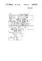
- FIGS. 2A-2C illustrate specific embodiments thereof.
- the armature for the motor 10 is adapted to be energized directly by the full wave bridge circuit 12, which includes a pair of silicon controlled rectifiers SCR 1 and SCR 2, one in each of the input legs of the bridge circuit, diodes D13 and D14 in the other legs of the bridge, the diode D15, resistor R39 and capacitor C21.
- A.c. input of either 120 v or 240 v is brought into the bridge circuit by way of terminals L1, L2.
- the output of the bridge circuit is connected to the armature of the motor 10 by way of terminals A+and A-, and the field coil of the motor is connected to the terminals F+and F-.
- a current sensing resistor R21 is connected to the armature of the motor at the terminal A-. This resistor serves to sense the current through the armature and develops a voltage proportional to the current. As an example, if the motor 10 develops 1 hp by drawing 10 amps d.c. at full load, approximately 100 millivolts is produced in the resistor R21. This voltage is fed into the two operative amplifiers: the current limiting circuit 16 and the current/resistance compensating circuit 20.
- the signal developed in the resistor R21 which is indicative of the voltage drop across the armature of the motor under various loading conditions, is utilized to provide compensating voltage for that lost by virtue of the internal resistance of the armature.
- This voltage is added to the voltage, which is normally impressed upon the motor for speed control during normal operation of the motor so that the motor is always induced with the proper voltage level indicative of operator demand.
- the motor 10 is a one horsepower motor, has a 10 amp rating, and with energization by 100 volts, it will provide 2000 rpm. If the voltage is reduced 50 volts, it will produce 1000 rpm.
- the compensating circuit 20 will produce the needed 10 volts, which can be pre-set when the motor load is to draw 10 amps, and to add this voltage to the speed amplifier circuit 26, as will be discussed below.
- the circuit 20 is linear, so that at 5 amps it will produce 5 volts and at 21/2 amps, it will produce 21/2 volts. In operation, then, in the example above, if 50 volts is normally induced into the motor, the control system will actually impress a total of 60 volts upon the motor.
- the voltage drop signal produced by the resistor R21 will also be conducted to the current limiting circuit 16, where it is amplified by amplifier IC2D.
- the amplified signal is directed to a high gain comparator consisting of the device directed to a high gain comparator consisting of the device IC2A in the trigger circuit 18, as one of its inputs.
- a potentiometer R29 connected as an input to IC2D is pre-set to adjust the threshold at which IC2D conducts.
- the capacitor C12 acts as a noise capacitor.
- a threshold is set up in IC2D, and when the voltage in the resistor R21 reaches the level pre-set in the potentiometer R29, the amplifier IC2D starts to conduct.
- the amplified signal from IC2D is conducted to the input side of a device IC2A in the trigger circuit 18. As the amplifier IC2D starts to conduct, it pulls the input to the comparator of IC2A to zero when the reference point of the amplifier IC2D is reached.
- a threshold in R29 is set with current limits of 15 amps.
- the current limiting circuit will not operate until the current starts to approach approximately 14.8-14.9 amps, and upon reaching 15 amps, the threshold of comparator IC2D starts to conduct, resulting in pulling of the signal away from resistor R22, whereupon IC2A levels off at the 15 amp level.
- the trigger circuit 18 includes transistors Q1 and Q2, which are adapted to change the phasing of the firing of the silicon controlled rectifiers SCR1 and SCR2.
- the transistor Q1 is used to synchronize the trigger with zero crossing voltage of the full wave rectified voltage on the sensor diode Z2, and the diode D7 serves as the isolation diode.
- the effect of changing of the phasing of IC2A is transmitted to the rectifiers SCR1, SCR2 for controlling the power input to the motor 10.
- the change in phasing by the transistors Q1 and Q2 is performed by way of the transformer T1, with the transistor Q2 actually serving as the firing component for the rectifiers SCR1, SCR2 through the transformer.
- FIG. 2A Operator control for the system of FIGS. 2A-2C is illustrated in FIG. 2A, in the form of the linear ramp generator 22 and the main speed device 24, which is the potentiometer R2.
- the potentiometer R2 is the main speed control for the operation of the motor 10 and is arranged to set up reference voltages which are conducted into amplifiers IC1A and IC1B.
- the amplifiers IC1A and IC1B, and their related electronic components, operate as accelerator and decelerator devices, respectively, in the operative responses of the motor.
- the circuit 22 functions to provide an operator settable pre-set delay in the conduction of electric power to the motor 10, regardless of whether the speed of the motor is up or down, or forward or in reverse. In this manner, motor speed increase or decrease is delayed in the event an operator manipulated the speed potentiometer R2 too rapidly in either direction. If the application for the control system is utilized, for example, in a paper processing machine, and if the motor responded too quickly, it may tear the web of paper being processed. On the other hand, if the motor in use suddenly stopped, mechanical inertia, especially with a high friction load, may cause damaging effects.
- the potentiometer R8, and associated diode Dl serve to vary the delayed time for an increase in motor speed
- the potentiometer R9 and diode D2 serve to vary the delayed time for a decrease in motor speed.
- the time delays may be adjustable from 0.2 to 10.0 seconds.
- the output signal of the ramp generator circuit 22, applied to resistor R13, is a d.c. filtered voltage. This signal follows the motion ff the potentiometer R2 with an adjustable delay.
- the compensating amplifier circuit 20 produces a signal indicative of the inherent internal resistance of the armature for the motor 10 for any load placed on the motor.
- This compensating signal is conducted by way of the resistor R34, to a junction between the resistor R13 and the voltage reference amplifier IC2B, which is in effect a speed error amplifier.
- This compensating signal as fed by R34, is added to the command signal from the ramp generator circuit 22, which is fed through the resistor R13. Their combined signal is transmitted to the motor supply circuit for energizing the motor in accordance with the total voltage.
- the speed error amplifier IC2B takes the error signals between R13, which is the reference speed, and the feedback voltage developed between the resistors R19 and R20.
- the amplifier measures the voltage across the output of the motor control and compares it with the reference voltage established out of the potentiometer setting of R2.
- the compensating network comprising IC2B, the capacitors C4, C5 and the resistor R15, serve to integrate and process the signal, and enhance the frequency response of the control.
- the automatic inhibit circuit 28 is actually a part of the supply circuitry for the motor 10. It is utilized to protect the motor from damage in the event the a.c. input is turned on and off very abruptly before the power supply capacitors have a chance to fully discharge.
- the capacitor C18 is charged.
- the transistor Q3 closes and discharges the voltage in C18 through the SCR switch Q4.
- the resistor R36 is one ohm
- the capacitor C19 is rated at 100 microfarad
- the time constant for discharge of the capacitor C19 is 100 microseconds. This arrangement, in effect, brings the capacitor voltage of C19 from approximately 22 volts down to one-half volt in a half a millisecond.
- control system for d.c. motor utilizes a separate and dedicated amplifier for current limiting control of the motor.
- current limit control is generally made available in a current limit control circuit which also provides for current/resistance compensation.
- the circuits 16 and 20 are generally combined into a single amplifier circuit, which performs the function of both circuits.
- the limitations inherent in the current/resistance compensation circuit, such as lag in response time is avoided.
- the same may be integrated into the speed control circuitry at a point which is more efficient in control processing than would be the case if a single, all purpose, amplifier were used.
- the integration of a dedicated current limit amplifier results in quick-acting response, which is not available with a multi-use amplifier.
- the quick-acting characteristic is augmented by virtue of the fact that the signal produced in the current limit amplifier is directly fed into the trigger circuit for the power supply for the motor being controlled.
- the present invention provides d.c. motor speed control, which is most responsive to operator demands, both as to preciseness and to timeliness.
- the present invention is particularly adapted to provide a drive which can be accurately applied in a very precise and timely manner.
- the trigger circuit 18 may utilize unijunction transistors, programmable unijunction transistors, or combinations of other transistors.
Abstract
Description
Claims (5)
Priority Applications (1)
| Application Number | Priority Date | Filing Date | Title |
|---|---|---|---|
| US07/186,597 US4839570A (en) | 1988-04-27 | 1988-04-27 | Current limiting control circuit for d.c. motors |
Applications Claiming Priority (1)
| Application Number | Priority Date | Filing Date | Title |
|---|---|---|---|
| US07/186,597 US4839570A (en) | 1988-04-27 | 1988-04-27 | Current limiting control circuit for d.c. motors |
Publications (1)
| Publication Number | Publication Date |
|---|---|
| US4839570A true US4839570A (en) | 1989-06-13 |
Family
ID=22685563
Family Applications (1)
| Application Number | Title | Priority Date | Filing Date |
|---|---|---|---|
| US07/186,597 Expired - Fee Related US4839570A (en) | 1988-04-27 | 1988-04-27 | Current limiting control circuit for d.c. motors |
Country Status (1)
| Country | Link |
|---|---|
| US (1) | US4839570A (en) |
Cited By (8)
| Publication number | Priority date | Publication date | Assignee | Title |
|---|---|---|---|---|
| US4990929A (en) * | 1988-12-15 | 1991-02-05 | Harada Kogyo Kabushiki Kaisha | Motor-driven automobile antenna with timer circuit |
| US5028854A (en) * | 1990-01-30 | 1991-07-02 | The Pillsbury Company | Variable speed motor drive |
| US5061884A (en) * | 1990-02-12 | 1991-10-29 | Kb Electronics, Inc. | Current limiting control circuit for D.C. motors with line dropout protection |
| US5134682A (en) * | 1987-05-27 | 1992-07-28 | Papst-Motoren Gmbh & Co. Kg | Driver circuit for a d.c. motor without commutator |
| US5351336A (en) * | 1992-07-17 | 1994-09-27 | Wilkerson A W | Motor control having improved speed regulation under intermittent loading |
| US5367600A (en) * | 1992-07-21 | 1994-11-22 | Wilkerson A W | Motor control for a treadmill having improved power supply and improved speed regulation under intermittent loading |
| US6460626B2 (en) | 1998-12-30 | 2002-10-08 | Black & Decker Inc. | Dual-mode non-isolated corded system for transportable cordless power tools |
| US9647444B2 (en) | 2015-06-16 | 2017-05-09 | Hamilton Sundstrand Corporation | Variable threshold current limiting circuit |
Citations (7)
| Publication number | Priority date | Publication date | Assignee | Title |
|---|---|---|---|---|
| US3551774A (en) * | 1969-04-04 | 1970-12-29 | Square D Co | Current limiting circuit for a solid state d.c. motor control circuit |
| US3999108A (en) * | 1972-08-16 | 1976-12-21 | Canon Kabushiki Kaisha | Speed regulation system for DC motors with hall generators |
| US4297623A (en) * | 1977-06-20 | 1981-10-27 | Compagnie Internationale Pour L'informatique Cii-Honeywell Bull | System for controlling a separately excited constant load DC electric motor |
| US4371818A (en) * | 1980-10-15 | 1983-02-01 | Minnesota Mining And Manufacturing Company | Spindle motor control system |
| US4468597A (en) * | 1981-02-11 | 1984-08-28 | Faiveley S.A. | Method for regulating the power supply to a direct-current motor and a device for the application of said method |
| US4511830A (en) * | 1978-08-29 | 1985-04-16 | Canon Kabushiki Kaisha | Servo control apparatus |
| US4514665A (en) * | 1983-01-05 | 1985-04-30 | Towmotor Corporation | Current limit control circuit |
-
1988
- 1988-04-27 US US07/186,597 patent/US4839570A/en not_active Expired - Fee Related
Patent Citations (7)
| Publication number | Priority date | Publication date | Assignee | Title |
|---|---|---|---|---|
| US3551774A (en) * | 1969-04-04 | 1970-12-29 | Square D Co | Current limiting circuit for a solid state d.c. motor control circuit |
| US3999108A (en) * | 1972-08-16 | 1976-12-21 | Canon Kabushiki Kaisha | Speed regulation system for DC motors with hall generators |
| US4297623A (en) * | 1977-06-20 | 1981-10-27 | Compagnie Internationale Pour L'informatique Cii-Honeywell Bull | System for controlling a separately excited constant load DC electric motor |
| US4511830A (en) * | 1978-08-29 | 1985-04-16 | Canon Kabushiki Kaisha | Servo control apparatus |
| US4371818A (en) * | 1980-10-15 | 1983-02-01 | Minnesota Mining And Manufacturing Company | Spindle motor control system |
| US4468597A (en) * | 1981-02-11 | 1984-08-28 | Faiveley S.A. | Method for regulating the power supply to a direct-current motor and a device for the application of said method |
| US4514665A (en) * | 1983-01-05 | 1985-04-30 | Towmotor Corporation | Current limit control circuit |
Cited By (9)
| Publication number | Priority date | Publication date | Assignee | Title |
|---|---|---|---|---|
| US5134682A (en) * | 1987-05-27 | 1992-07-28 | Papst-Motoren Gmbh & Co. Kg | Driver circuit for a d.c. motor without commutator |
| US4990929A (en) * | 1988-12-15 | 1991-02-05 | Harada Kogyo Kabushiki Kaisha | Motor-driven automobile antenna with timer circuit |
| US5028854A (en) * | 1990-01-30 | 1991-07-02 | The Pillsbury Company | Variable speed motor drive |
| US5061884A (en) * | 1990-02-12 | 1991-10-29 | Kb Electronics, Inc. | Current limiting control circuit for D.C. motors with line dropout protection |
| US5351336A (en) * | 1992-07-17 | 1994-09-27 | Wilkerson A W | Motor control having improved speed regulation under intermittent loading |
| US5367600A (en) * | 1992-07-21 | 1994-11-22 | Wilkerson A W | Motor control for a treadmill having improved power supply and improved speed regulation under intermittent loading |
| US6460626B2 (en) | 1998-12-30 | 2002-10-08 | Black & Decker Inc. | Dual-mode non-isolated corded system for transportable cordless power tools |
| US6675912B2 (en) | 1998-12-30 | 2004-01-13 | Black & Decker Inc. | Dual-mode non-isolated corded system for transportable cordless power tools |
| US9647444B2 (en) | 2015-06-16 | 2017-05-09 | Hamilton Sundstrand Corporation | Variable threshold current limiting circuit |
Similar Documents
| Publication | Publication Date | Title |
|---|---|---|
| US4574226A (en) | Method and apparatus for controlling an electric motor the rotational speed of which is automatically reduced in no-load idling operation | |
| US3950684A (en) | Direct current motor speed control apparatus | |
| US4851170A (en) | Injection control method of injection molding machine | |
| US4079301A (en) | D.C. motor control | |
| US4240015A (en) | Control system and method for operating a DC motor | |
| US4839570A (en) | Current limiting control circuit for d.c. motors | |
| JPH0361016B2 (en) | ||
| US4297623A (en) | System for controlling a separately excited constant load DC electric motor | |
| US4443750A (en) | Energy saving motor speed controller | |
| US4378517A (en) | Method and apparatus for controlling the energization of an electric motor | |
| US3701556A (en) | Control system for diesel locomotive | |
| US5061884A (en) | Current limiting control circuit for D.C. motors with line dropout protection | |
| US3995208A (en) | Control circuit | |
| US3555386A (en) | Control apparatus for motors and the like | |
| US4915162A (en) | Method and apparatus for heater current control for automatic vending machine | |
| US4302711A (en) | DC Servomotor circuit having drive current controlled as a function of motor speed | |
| US3935520A (en) | DC motor regulator | |
| CA1105119A (en) | Automatic control system with integrator offset | |
| GB2159011A (en) | Electric vehicle current regulator | |
| GB1531346A (en) | Regenerative motor control having field and armature coordinating means | |
| US4441009A (en) | Arc voltage control circuit for welding apparatus | |
| US3789229A (en) | Welding control circuit and method | |
| JPS63191B2 (en) | ||
| RU2239936C2 (en) | Method for controlling synchronous motor field current | |
| US3536971A (en) | Inherent current limit circuit |
Legal Events
| Date | Code | Title | Description |
|---|---|---|---|
| AS | Assignment |
Owner name: KB ELECTRONICS INC., 73 WORTMAN AAVENUE, BROOKLYN, Free format text: ASSIGNMENT OF ASSIGNORS INTEREST.;ASSIGNOR:SAGANOVSKY, ABRAHAM;REEL/FRAME:004867/0506 Effective date: 19880419 Owner name: KB ELECTRONICS INC.,NEW YORK Free format text: ASSIGNMENT OF ASSIGNORS INTEREST;ASSIGNOR:SAGANOVSKY, ABRAHAM;REEL/FRAME:004867/0506 Effective date: 19880419 |
|
| FEPP | Fee payment procedure |
Free format text: PAYOR NUMBER ASSIGNED (ORIGINAL EVENT CODE: ASPN); ENTITY STATUS OF PATENT OWNER: LARGE ENTITY Free format text: PAT HLDR NO LONGER CLAIMS SMALL ENT STAT AS SMALL BUSINESS (ORIGINAL EVENT CODE: LSM2); ENTITY STATUS OF PATENT OWNER: LARGE ENTITY |
|
| FEPP | Fee payment procedure |
Free format text: PAYOR NUMBER ASSIGNED (ORIGINAL EVENT CODE: ASPN); ENTITY STATUS OF PATENT OWNER: LARGE ENTITY Free format text: PAYER NUMBER DE-ASSIGNED (ORIGINAL EVENT CODE: RMPN); ENTITY STATUS OF PATENT OWNER: LARGE ENTITY |
|
| FPAY | Fee payment |
Year of fee payment: 4 |
|
| FEPP | Fee payment procedure |
Free format text: PAYER NUMBER DE-ASSIGNED (ORIGINAL EVENT CODE: RMPN); ENTITY STATUS OF PATENT OWNER: LARGE ENTITY Free format text: PAYOR NUMBER ASSIGNED (ORIGINAL EVENT CODE: ASPN); ENTITY STATUS OF PATENT OWNER: LARGE ENTITY |
|
| FPAY | Fee payment |
Year of fee payment: 8 |
|
| REFU | Refund |
Free format text: REFUND PROCESSED. MAINTENANCE FEE HAS ALREADY BEEN PAID (ORIGINAL EVENT CODE: R160); ENTITY STATUS OF PATENT OWNER: LARGE ENTITY |
|
| FEPP | Fee payment procedure |
Free format text: PAYER NUMBER DE-ASSIGNED (ORIGINAL EVENT CODE: RMPN); ENTITY STATUS OF PATENT OWNER: LARGE ENTITY Free format text: PAYOR NUMBER ASSIGNED (ORIGINAL EVENT CODE: ASPN); ENTITY STATUS OF PATENT OWNER: LARGE ENTITY |
|
| REMI | Maintenance fee reminder mailed | ||
| LAPS | Lapse for failure to pay maintenance fees | ||
| FP | Lapsed due to failure to pay maintenance fee |
Effective date: 20010613 |
|
| STCH | Information on status: patent discontinuation |
Free format text: PATENT EXPIRED DUE TO NONPAYMENT OF MAINTENANCE FEES UNDER 37 CFR 1.362 |