US4823357A - Diffraction limited dichroic combiner diode laser - Google Patents
Diffraction limited dichroic combiner diode laser Download PDFInfo
- Publication number
- US4823357A US4823357A US06/928,356 US92835686A US4823357A US 4823357 A US4823357 A US 4823357A US 92835686 A US92835686 A US 92835686A US 4823357 A US4823357 A US 4823357A
- Authority
- US
- United States
- Prior art keywords
- laser
- beams
- combined
- diode
- discrete wavelengths
- Prior art date
- Legal status (The legal status is an assumption and is not a legal conclusion. Google has not performed a legal analysis and makes no representation as to the accuracy of the status listed.)
- Expired - Fee Related
Links
Images


Classifications
-
- G—PHYSICS
- G02—OPTICS
- G02B—OPTICAL ELEMENTS, SYSTEMS OR APPARATUS
- G02B6/00—Light guides; Structural details of arrangements comprising light guides and other optical elements, e.g. couplings
- G02B6/24—Coupling light guides
- G02B6/42—Coupling light guides with opto-electronic elements
- G02B6/4201—Packages, e.g. shape, construction, internal or external details
- G02B6/4246—Bidirectionally operating package structures
-
- G—PHYSICS
- G02—OPTICS
- G02B—OPTICAL ELEMENTS, SYSTEMS OR APPARATUS
- G02B6/00—Light guides; Structural details of arrangements comprising light guides and other optical elements, e.g. couplings
- G02B6/24—Coupling light guides
- G02B6/42—Coupling light guides with opto-electronic elements
- G02B6/4201—Packages, e.g. shape, construction, internal or external details
- G02B6/4249—Packages, e.g. shape, construction, internal or external details comprising arrays of active devices and fibres
-
- H—ELECTRICITY
- H01—ELECTRIC ELEMENTS
- H01S—DEVICES USING THE PROCESS OF LIGHT AMPLIFICATION BY STIMULATED EMISSION OF RADIATION [LASER] TO AMPLIFY OR GENERATE LIGHT; DEVICES USING STIMULATED EMISSION OF ELECTROMAGNETIC RADIATION IN WAVE RANGES OTHER THAN OPTICAL
- H01S5/00—Semiconductor lasers
- H01S5/02—Structural details or components not essential to laser action
- H01S5/022—Mountings; Housings
- H01S5/023—Mount members, e.g. sub-mount members
- H01S5/02325—Mechanically integrated components on mount members or optical micro-benches
-
- H—ELECTRICITY
- H01—ELECTRIC ELEMENTS
- H01S—DEVICES USING THE PROCESS OF LIGHT AMPLIFICATION BY STIMULATED EMISSION OF RADIATION [LASER] TO AMPLIFY OR GENERATE LIGHT; DEVICES USING STIMULATED EMISSION OF ELECTROMAGNETIC RADIATION IN WAVE RANGES OTHER THAN OPTICAL
- H01S5/00—Semiconductor lasers
- H01S5/02—Structural details or components not essential to laser action
- H01S5/024—Arrangements for thermal management
- H01S5/02407—Active cooling, e.g. the laser temperature is controlled by a thermo-electric cooler or water cooling
- H01S5/02415—Active cooling, e.g. the laser temperature is controlled by a thermo-electric cooler or water cooling by using a thermo-electric cooler [TEC], e.g. Peltier element
-
- H—ELECTRICITY
- H01—ELECTRIC ELEMENTS
- H01S—DEVICES USING THE PROCESS OF LIGHT AMPLIFICATION BY STIMULATED EMISSION OF RADIATION [LASER] TO AMPLIFY OR GENERATE LIGHT; DEVICES USING STIMULATED EMISSION OF ELECTROMAGNETIC RADIATION IN WAVE RANGES OTHER THAN OPTICAL
- H01S5/00—Semiconductor lasers
- H01S5/40—Arrangement of two or more semiconductor lasers, not provided for in groups H01S5/02 - H01S5/30
- H01S5/4012—Beam combining, e.g. by the use of fibres, gratings, polarisers, prisms
-
- G—PHYSICS
- G02—OPTICS
- G02B—OPTICAL ELEMENTS, SYSTEMS OR APPARATUS
- G02B6/00—Light guides; Structural details of arrangements comprising light guides and other optical elements, e.g. couplings
- G02B6/24—Coupling light guides
- G02B6/26—Optical coupling means
- G02B6/28—Optical coupling means having data bus means, i.e. plural waveguides interconnected and providing an inherently bidirectional system by mixing and splitting signals
- G02B6/293—Optical coupling means having data bus means, i.e. plural waveguides interconnected and providing an inherently bidirectional system by mixing and splitting signals with wavelength selective means
- G02B6/29346—Optical coupling means having data bus means, i.e. plural waveguides interconnected and providing an inherently bidirectional system by mixing and splitting signals with wavelength selective means operating by wave or beam interference
- G02B6/29358—Multiple beam interferometer external to a light guide, e.g. Fabry-Pérot, etalon, VIPA plate, OTDL plate, continuous interferometer, parallel plate resonator
-
- G—PHYSICS
- G02—OPTICS
- G02B—OPTICAL ELEMENTS, SYSTEMS OR APPARATUS
- G02B6/00—Light guides; Structural details of arrangements comprising light guides and other optical elements, e.g. couplings
- G02B6/24—Coupling light guides
- G02B6/26—Optical coupling means
- G02B6/28—Optical coupling means having data bus means, i.e. plural waveguides interconnected and providing an inherently bidirectional system by mixing and splitting signals
- G02B6/293—Optical coupling means having data bus means, i.e. plural waveguides interconnected and providing an inherently bidirectional system by mixing and splitting signals with wavelength selective means
- G02B6/29346—Optical coupling means having data bus means, i.e. plural waveguides interconnected and providing an inherently bidirectional system by mixing and splitting signals with wavelength selective means operating by wave or beam interference
- G02B6/29361—Interference filters, e.g. multilayer coatings, thin film filters, dichroic splitters or mirrors based on multilayers, WDM filters
- G02B6/29362—Serial cascade of filters or filtering operations, e.g. for a large number of channels
- G02B6/29365—Serial cascade of filters or filtering operations, e.g. for a large number of channels in a multireflection configuration, i.e. beam following a zigzag path between filters or filtering operations
- G02B6/29367—Zigzag path within a transparent optical block, e.g. filter deposited on an etalon, glass plate, wedge acting as a stable spacer
-
- G—PHYSICS
- G02—OPTICS
- G02B—OPTICAL ELEMENTS, SYSTEMS OR APPARATUS
- G02B6/00—Light guides; Structural details of arrangements comprising light guides and other optical elements, e.g. couplings
- G02B6/24—Coupling light guides
- G02B6/42—Coupling light guides with opto-electronic elements
- G02B6/4201—Packages, e.g. shape, construction, internal or external details
- G02B6/4204—Packages, e.g. shape, construction, internal or external details the coupling comprising intermediate optical elements, e.g. lenses, holograms
- G02B6/4215—Packages, e.g. shape, construction, internal or external details the coupling comprising intermediate optical elements, e.g. lenses, holograms the intermediate optical elements being wavelength selective optical elements, e.g. variable wavelength optical modules or wavelength lockers
-
- G—PHYSICS
- G02—OPTICS
- G02B—OPTICAL ELEMENTS, SYSTEMS OR APPARATUS
- G02B6/00—Light guides; Structural details of arrangements comprising light guides and other optical elements, e.g. couplings
- G02B6/24—Coupling light guides
- G02B6/42—Coupling light guides with opto-electronic elements
- G02B6/4201—Packages, e.g. shape, construction, internal or external details
- G02B6/4256—Details of housings
- G02B6/4257—Details of housings having a supporting carrier or a mounting substrate or a mounting plate
- G02B6/4259—Details of housings having a supporting carrier or a mounting substrate or a mounting plate of the transparent type
-
- G—PHYSICS
- G02—OPTICS
- G02B—OPTICAL ELEMENTS, SYSTEMS OR APPARATUS
- G02B6/00—Light guides; Structural details of arrangements comprising light guides and other optical elements, e.g. couplings
- G02B6/24—Coupling light guides
- G02B6/42—Coupling light guides with opto-electronic elements
- G02B6/4201—Packages, e.g. shape, construction, internal or external details
- G02B6/4266—Thermal aspects, temperature control or temperature monitoring
- G02B6/4268—Cooling
- G02B6/4271—Cooling with thermo electric cooling
-
- H—ELECTRICITY
- H01—ELECTRIC ELEMENTS
- H01S—DEVICES USING THE PROCESS OF LIGHT AMPLIFICATION BY STIMULATED EMISSION OF RADIATION [LASER] TO AMPLIFY OR GENERATE LIGHT; DEVICES USING STIMULATED EMISSION OF ELECTROMAGNETIC RADIATION IN WAVE RANGES OTHER THAN OPTICAL
- H01S5/00—Semiconductor lasers
- H01S5/005—Optical components external to the laser cavity, specially adapted therefor, e.g. for homogenisation or merging of the beams or for manipulating laser pulses, e.g. pulse shaping
- H01S5/0078—Optical components external to the laser cavity, specially adapted therefor, e.g. for homogenisation or merging of the beams or for manipulating laser pulses, e.g. pulse shaping for frequency filtering
-
- H—ELECTRICITY
- H01—ELECTRIC ELEMENTS
- H01S—DEVICES USING THE PROCESS OF LIGHT AMPLIFICATION BY STIMULATED EMISSION OF RADIATION [LASER] TO AMPLIFY OR GENERATE LIGHT; DEVICES USING STIMULATED EMISSION OF ELECTROMAGNETIC RADIATION IN WAVE RANGES OTHER THAN OPTICAL
- H01S5/00—Semiconductor lasers
- H01S5/02—Structural details or components not essential to laser action
- H01S5/024—Arrangements for thermal management
- H01S5/02453—Heating, e.g. the laser is heated for stabilisation against temperature fluctuations of the environment
-
- H—ELECTRICITY
- H01—ELECTRIC ELEMENTS
- H01S—DEVICES USING THE PROCESS OF LIGHT AMPLIFICATION BY STIMULATED EMISSION OF RADIATION [LASER] TO AMPLIFY OR GENERATE LIGHT; DEVICES USING STIMULATED EMISSION OF ELECTROMAGNETIC RADIATION IN WAVE RANGES OTHER THAN OPTICAL
- H01S5/00—Semiconductor lasers
- H01S5/40—Arrangement of two or more semiconductor lasers, not provided for in groups H01S5/02 - H01S5/30
- H01S5/4025—Array arrangements, e.g. constituted by discrete laser diodes or laser bar
- H01S5/4087—Array arrangements, e.g. constituted by discrete laser diodes or laser bar emitting more than one wavelength
Definitions
- the present invention relates generally to laser communication systems, and more specifically to a laser transmitter which uses dichroic combination to combine the output beams of numerous diode lasers into a single diffraction-limited beam.
- the laser beams of spaceborne laser communication systems must travel great distances (100 to 1,000 miles) in links involving space platforms. To achieve adequate signal margins for acquisition, track, and communication the beams must be focussed very sharply with minimum beam divergence so that the received beam appears to be its brightest (maximum irradiance). The optimum condition occurs when a full aperture beam is emitted from a near perfect (diffraction limited) telescopic optical system. If the source laser produces a near perfect beam, a diffraction limited telescope can project the laser beam into the brightest possible signal at the receiver.
- Laser diodes are small, efficient, and their low voltage drive requirements are compatible with the signal levels available from highly reliable solid state circuit components. In the design of a laser transmitter these features are important because they result in decreased system size and weight, reduced cooling and electrical requirements, and increased overall system reliability.
- the favorable mechanical and electrical characteristics of laser diodes are complemented by a number of useful optical properties.
- the operating wavelength of a laser diode may be accurately tuned over a broad range by controlling either the diode temperature or drive current.
- the output power of a laser diode may be directly modulated at frequencies up to several gigahertz by modulating the diode drive current. Separate modulator crystals and high voltage drive electronics are not required.
- laser diodes can be made to provide a single axial mode output. They are also highly polarized, a property which would be useful in combining, separating, or isolating signals.
- the d'Auria et al patent is pertinent for its disclosure of a transmitting and receiving system with independent communication channels in a single optical fiber.
- a plurality of laser diodes supply infrared rays of different wavelengths to respective ones of a series of selective mirrors.
- the mirrors are tilted at a 45 degree angle and downstream beams are directed to the exit sides of the mirrors where they are reflected and combined with the beams passing through from the upstream sides of the mirrors. In this way, the light radiation from the diodes is multiplexed to the single fiber.
- Eberly et al provide an optical communications system which uses pulses of different wavelength and/or polarization.
- Ahearn shows a gallium arsenide laser diode array.
- the present invention is a laser transmitter which combines numerous single longitudinal mode diodes using dichroic combination to produce a high power, diffraction limited beam which may be transmitted at minimum beam divergence using the full aperture of a transmitter telescope.
- One embodiment of the present invention is a laser transmitter composed of: six diode lasers, five narrow band filters, a 2% beam splitter, a variably tilted interference filter, a photodiode detector, and a wavelength controller circuit.
- the output beams of six diodes are sequentially added by the successive transmission through (and subsequent reflection from) the five narrowband filters.
- Each of the narrowband filters superimposes and collimates received laser beams to produce a combined laser beam as follows.
- the first diode laser produces a collimated beam of a first wavelength, which is directed at a narrowband or long wave pass filter that is tilted slightly (about 10 degrees). This beam passes through the filter.
- a beam of a second wavelength from the second diode laser is directed toward the exit side of the filter (which acts as a mirror) at such an angle that the second beam is reflected colinear with the first beam and superimposed on it.
- Each of the subsequent narrowband filters perform a dichroic combination of received laser beams by superimposing each subsequent laser beam onto the combined laser beam.
- This combined laser beam is sampled by the 2% beam splitter which outputs 98% of the combined laser beam while forwarding a 2% sample laser beam to the tilted interference filter.
- the tilted interference filter produces filtered sample beams by adjustably filtering the sample laser beam into the wavelengths ideally produced by each of the diode lasers. These filtered sample beams are received by the photodiode detector.
- the photodiode detector is a commercially available photodiode which monitors the optical power of the filtered sample laser beams by being operated in the photovoltaic mode, and detecting the center wavelengths ideally produced by each of the diode lasers. The photodiode detector produces detection signals which indicates whether the diode lasers need to be adjusted.
- the detection of the signals of the photodiode are received by the wavelength controller circuit which responds by producing adjustment signals to each diode laser, as required to adjust the wavelengths of the laser beams produced by them.
- the adjustment signals adjust the wavelengths of the laser diodes by producing minute changes in the operating temperatures of the laser diode.
- FIGS. 1 and 2 are illustrations of two embodiments of the present invention.
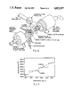
- FIG. 3 is a chart of the measures of the filtered outputs of the laser sources of FIG. 2;
- FIG. 4 is a view of a thermal adjusting element which is placed in proximity to a laser diode
- FIG. 5 is an electrical schematic of the driver circuit which controls the thermal adjusting element depicted in FIG. 4;
- FIG. 6 is a detailed illustration of the beamsplitter, optical encoder and tilted filter of the system of FIG. 1;
- FIG. 7 is a chart depicting the temperature dependence of the lasing wavelengths of a laser.
- the present invention provides the dichroic combination of the outputs of numerous longitudinal diode lasers into a single, combined laser beam.
- FIG. 1 is an illustration of the multireflection dichroic combiner laser of the present invention.
- the system of FIG. 1 uses: five diode lasers T 1 -T 5 , four narrow band filters 101-104, a 2% beam splitter 100, an interference filter 201, a detector 203, and a wavelength controller circuit 204.
- the diode laser sources T 1 -T 5 may be commercially available GaAs or GaAlAs diode lasers or diode laser arrays with output ranges from 8,000 to 8,8000 angstroms.
- the diode lasers T 1 -T 5 respectively output ⁇ 1 - ⁇ 5 laser beams with center wavelengths spaced 20 angstroms apart for a total bandpass of less than 100 angstroms.
- the narrowband filters 101-104 are used for the dichroic combination of laser beams ⁇ 1 - ⁇ 5 as follows.
- Filter 101 has a bandpass is such that ⁇ 1 light reflects from it while light from diode T 2 is transmitted.
- the filters 101-104 are stepped in their center bandpass in 20 angstrom increments, and each diode's light in turn is transmitted by its own filter only to be reflected by each subsequent filter in the sequence.
- each filter is tilted slightly (about 10 degrees) with respect to a plane normal to the incident laser beams.
- the 95% reflectivity of filter 101 reflects the ⁇ 1 light of laser T 1 , while the 92% transmissivity of filter 101 superimposes the ⁇ 2 light onto the ⁇ 1 light.
- the reflectivity of filter 102 reflects the ⁇ 1 and ⁇ 2 beams while its 92% transmissivity superimposes the ⁇ 3 light from laser diode T 3 onto the ⁇ 1 and ⁇ 2 beams. This process continues until the last narrowband filter 104 outputs a combined beam which includes the beams from all the T 1 -T 5 laser diodes.
- the combined laser beam produced by the last narrowband filter 104 is output and sampled by the 2% beamsplitter 100.
- This is also a commercially available optical element, and need not be described other than to observe that it outputs 98% of the combined laser beam while forwarding a 2% sample laser beam to the tilted interference filter 201.
- the tilted interference filter 201 is also a commercially available device which produces filtered samples beams by adjustably filtering the sample laser beam into the wavelengths ideally produced by each of the diode lasers T 1 -T 5 . These filtered sample beams are received by the photodiode detector 203.
- the photodiode detector 203 is a Hewlett-Packard photodiode which is operated in the photovoltiac mode to monitor the optical power of the filtered sample laser beams from the tilted interference filter 101.
- the photodiode detector 203 is set to detect the center wavelengths ideally produced by each of the diode lasers T 1 -T 5 , and produce detection signals which indicate whether the diode lasers need to be adjusted.
- the detection signals of the photodiode detector 203 are received by the wavelength controller circuit 204 which responds by producing adjustment signals to each diode laser, as required to adjust the wavelengths of the laser beams produced by them.
- the adjustment signals adjust the wavelengths of the laser diodes by producing minute changes in the operating temperature of the laser diode.
- the wavelength controller circuit and the process of thermal adjustment of the laser diodes is discussed in detail below.
- FIG. 2 is a schematic of another embodiment of the present invention, in which the output beams ⁇ 1 - ⁇ 6 of six diodes is sequentially added by the successive transmission and subsequent reflection by five narrowband filters.
- the purpose of FIG. 2 is to illustrate an example of a finished dichroic combining system and to emphasize that the system of FIG. 1 is just an example of the present invention. More specifically, the system of FIG. 2 is used to introduce FIG. 3 which is a chart of the measured filter transmissions for ⁇ 1 - ⁇ 6 of the laser beams of FIG. 2.
- FIG. 3 is meant to serve as a guideline for the operating characteristics of the laser diodes used in the invention. Progressive summing occurs from shorter to longer wavelengths.
- the GaAlAs diodes of FIG. 1 and 2 are capable of wavelengths ranging from 8,000 to 8,800 angstroms, but are set with wavelength separations of 20 angstroms, as illustrated in FIG. 3.
- the dichroic summing of the present invention is possible because of the availability of narrowband interference filters with extremely sharp transmission/reflection transitions. Narrowband interference filters are used instead of long or short wavelength bandpass filters because much steeper transmission slopes are available.
- the measured transmission curves of the five filters are shown in FIG. 3. The peak transmission of the mounted filters is close to 90% while the reflection efficiency is about 95%.
- each diode must run with nearly all of its power confined to the assigned passband.
- diode spacing is 20 angstroms
- the target passband for each diode is about 10 angstroms wide since operation outside this band results in unacceptable reflection and transmission losses at the adjacent passband interface.
- the diode beams must be collimated.
- a diffracion limited collimating lens is required if the diode wavefront quality is to be maintained.
- the combiner arrangement of FIG. 2 uses narrow bandpass filters bonded onto a high quality BK-7 glass block whose filter faces are precisely parallel.
- the laser diode collimated beams are tilted slightly with respect to the narrowband filters to provide beam translation along the block providing adequate spacing between adjacent diode collimator assemblies. If the beam tilt relative to the filters is held to 15 degrees or less, little polarization effect is realized and the inherently strong diode linear polarization is maintained. For this laser, 10 degrees was chosen as the angle of incidence.
- the collimator lens numerical aperture in the system of FIG. 2, was chosen to accept the most divergent diode beam, 68.5 degrees full angle at the 1/e 2 point.
- the lens was supplied by Optics Plus, Inc., using a model LDCO-62 diode collimator lens which was modified to accommodate the etalon in the back focal space and include an Invar barrel.
- the design is operable over a broad spectral operating range of 633 to 905 nm.
- the field of view is 30 milliradians and, as analyzed by ray tracing, the RMS wavefront error is one twenty-third wave over the field. Interferometric testing of the diode-etalon-lens combination showed total wavefront error of better than one-sixteenth wave verifying the diffraction limited lens image quality.
- the filters in FIG. 2 are bonded to the glass combiner block using an index matching cement.
- the glass combiner block supplied by Muffoletto Optical Co., is thermally controlled by upper and lower surface thermofoil heaters which control the block to a preset value within 0.2° C. This control is done for two reasons. First the narrowband filters are held at a constant temperature although they do not require a high degree of thermal control precision since their temperature coefficient (wavelength) is +0.22 angstroms per degree C. Second, and more important, negligible thermal gradients are maintained in the block to assure minimal wavefront degradiation as the beams traverse the block. The wavefront variation in a single traverse of the block is 0.0067 waves rms for a gradient of 0.02° C., which is negligible.
- each laser diode may also be actively controlled by adjusting the diode junction temperature using a thermo-electric cooler for each diode.
- FIG. 4 Another technique is depicted in FIG. 4, in which each laser diode 400 is mounted on a copper heat sink 401.
- a thermistor 402 is mounted adjacent to the laser diode and functions as a heater to allow thermal control of the wavelengths of the laser diode 400.
- a glass etalon 405. This is a driver which supplies current to the 120 ohm thermistor 402.
- a schematic of an etalon driver circuit is depicted in FIG. 5.
- the etalon driver circuit of FIG. 5 receives a logic "1" to turn the heater off, and a logic "0" to turn the heater on. Since each of the diodes operates at different wavelengths, they are held at different temperatures.
- the 120 ohm diode heater in FIG. 5 is activated to keep its laser diode at the appropriate operating temperature.
- An example of a temperature distribution between three GaAlAs diodes that produces the 20 angstrom separation is: 16° C. (60.8° F.), 20° C. (68.O° F.), and 24° C. (75.2° F.). All the dichroic filters in the combiner block of FIG. 2 are designed for operation at 24° C., but each design will change depending upon the type of diode laser selected.
- the detector 203 was identified as a commericially available photodiode obtained from Hewlett-Packard.
- the tilted interference filter 201 is a commercially available spike filter which is electrically connected with an ITEK 15 bit optical encoder 202, and which has the spike filter characteristics presented below in Table 1.
- FIG. 6 is an illustration of the beam splitter 100, optical encoder 202, spike filter 201 and detector 203 used in the embodiment of FIG. 1.
- the beam-splitter 100 is used to direct a small percentage of the laser power from the main beam onto the tilting filter 201.
- Angular orientation of the tilting filter is accomplished through direct drive by an Aeroflex brushless D.C. limited rotation motor (LRM) 600.
- LRM Aeroflex brushless D.C. limited rotation motor
- Bendix flex-pivots of the type used in torque motor beam steerers are used as bearings.
- the tilting filter 201 produces filtered sample beams by filtering the sample laser beam into the wavelengths ideally produced by each of the laser diodes. Examples of expected wavelength values are given in the chart of FIG. 3.
- the the filtered sample beams are received by the photodiode detector 203 which produces detector signals which indicate whether the diode lasers need to be adjusted.
- the detection signals of the photodiode 203 are received by a wavelength controller circuit which responds by producing adjustment signals to each diode laser, to adjust the wavelengths of the laser beams produced by them.
- the wavelength controller circuit for each diode laser consists of the etalon driver circuit depicted in FIG. 5.
- the 120 ohm heater remains off as long as the circuit is receiving a logic "1" from the photodiode detector.
- the photodiode detector 203 ceases to produce an output that particular etalon driver circuit. The result is that the 120 ohm heater is activated to drive the laser diode back up into its operating temperature range (until the photodiode detector begins detecting sufficient light to produce a logic "1" detection signal.
- FIG. 7 is a chart depicting the discrete lasing wavelengths emitted by a laser diode under different temperature ranges. The present invention takes advantage of this phenomenon to tune the diode lasers to emit discrete wavelengths.
- the wavelength of each diode is actively controlled by controlling the junction temperature using a thermo-electric cooler for each diode.
- the sensing of the wavelength of each diode may also be performed at the summed output of the laser by spectrally scanning with a filter wheel, or the variably tilted interference filter described above.
- the wavelength may be sensed at the diode output using two overlapping narrowband interference filters, one centered slightly above and the other slightly below the desired center wavelength of the diode.
- the back of each filter, in such a system would contain a separate photodetector.
- the sum and difference signals of the two detectors would provide feedback to actively control the diode wavelength keeping it positioned in its bandpass.
- the output of the laser of the present invention is diffraction limited, and produces the brightest possible far field pattern.
- the output may be circularized by use of a single group of anamorphic optics and subsequently combined with another combined beam using a polarization beam combiner, thereby doubling the laser output in the same overall bandpass.
Abstract
Description
              TABLE 1
______________________________________
SPIKE FILTER CHARACTERISTICS
______________________________________
CENTER WAVELENGTH
                 837 NM ± 0.5 NM
                 @ NORMAL INCIDENCE
BANDPASS (FWHM)  2.0 A ± 0.5 A
TRANSMISSION     50%
CAVITY DESIGN    SINGLE
BLOCKING         SPIKE ONLY 10.sup.-3
                 ON EITHER SIDE
SIZE             12.5 MM DIA. ± 0.25 MM
                 0.150 IN. ± 0.010 IN.
                 THICK
WAVELENGTH TEMP. +0.21 A/C°
COEFFICIENT
SEALING          HERMETIC-ANODIZED AL.
                 RING
COATINGS         A-R (MgF.sub.2) @ 830 NM
                 BOTH SIDES
OPTICAL QUALITY  2 WAVES IN
                 TRANSMISSION
ANGLE OF INCIDENCE
                 0 TO 20° MAX.
______________________________________
Claims (5)
Priority Applications (1)
| Application Number | Priority Date | Filing Date | Title |
|---|---|---|---|
| US06/928,356 US4823357A (en) | 1986-11-10 | 1986-11-10 | Diffraction limited dichroic combiner diode laser |
Applications Claiming Priority (1)
| Application Number | Priority Date | Filing Date | Title |
|---|---|---|---|
| US06/928,356 US4823357A (en) | 1986-11-10 | 1986-11-10 | Diffraction limited dichroic combiner diode laser |
Publications (1)
| Publication Number | Publication Date |
|---|---|
| US4823357A true US4823357A (en) | 1989-04-18 |
Family
ID=25456132
Family Applications (1)
| Application Number | Title | Priority Date | Filing Date |
|---|---|---|---|
| US06/928,356 Expired - Fee Related US4823357A (en) | 1986-11-10 | 1986-11-10 | Diffraction limited dichroic combiner diode laser |
Country Status (1)
| Country | Link |
|---|---|
| US (1) | US4823357A (en) |
Cited By (37)
| Publication number | Priority date | Publication date | Assignee | Title |
|---|---|---|---|---|
| US5048911A (en) * | 1988-11-15 | 1991-09-17 | Universiti Malaya | Coupling of multiple laser beams to a single optical fiber |
| US5097477A (en) * | 1991-05-07 | 1992-03-17 | The United States Of America As Represented By The Secretary Of The Navy | Laser diode pumped multiple rod ring laser allowing combination of multiple pump sources |
| WO1992009910A1 (en) * | 1990-11-21 | 1992-06-11 | Polaroid Corporation | Radiation source for a printer |
| US5164858A (en) * | 1990-03-07 | 1992-11-17 | Deposition Sciences, Inc. | Multi-spectral filter |
| US5185758A (en) * | 1989-11-28 | 1993-02-09 | Massachusetts Institute Of Technology | Multiple-laser pump optical system |
| US5231642A (en) * | 1992-05-08 | 1993-07-27 | Spectra Diode Laboratories, Inc. | Semiconductor ring and folded cavity lasers |
| US5276695A (en) * | 1992-10-26 | 1994-01-04 | The United States Of America As Represented By The Secretary Of The Navy | Multifrequency, rapidly sequenced or simultaneous tunable laser |
| US5307430A (en) * | 1992-11-30 | 1994-04-26 | The United States Of America As Represented By The United States Department Of Energy | Lensing duct |
| US5309282A (en) * | 1992-07-17 | 1994-05-03 | The United States Of America As Represented By The United States Department Of Energy | High stability wavefront reference source |
| EP0735397A2 (en) * | 1995-03-29 | 1996-10-02 | Siemens Aktiengesellschaft | Micro-optical device for transforming beams of a laser diode array and method for the production of such a device |
| US5586132A (en) * | 1994-07-27 | 1996-12-17 | Laser Industries Ltd. | Method and apparatus for generating bright light sources |
| WO1997009759A1 (en) * | 1995-09-01 | 1997-03-13 | Fraunhofer-Gesellschaft zur Förderung der angewandten Forschung e.V. | Laser process and device for scaling frequency-doubled lasers |
| US5715270A (en) * | 1996-09-27 | 1998-02-03 | Mcdonnell Douglas Corporation | High efficiency, high power direct diode laser systems and methods therefor |
| US5903393A (en) * | 1997-12-04 | 1999-05-11 | Kalibjian; Ralph | Optical-hybrid etalons for simultaneous phase- and polarization-diversity operations |
| US6101037A (en) * | 1997-07-25 | 2000-08-08 | Samsung Electronics Co., Ltd. | Apparatus and a method for combining light beams by using two flat plates with an air gap therebetween |
| US6141136A (en) * | 1999-08-27 | 2000-10-31 | Kalibjian; Ralph | Active phase-shift control in optical-hybrid etalons |
| WO2000077556A1 (en) * | 1999-06-11 | 2000-12-21 | University Of Hawaii | Mems optical components |
| US6259560B1 (en) | 1999-04-16 | 2001-07-10 | The United States Of America As Represented By The Secretary Of The Navy | Continuously variable beam combiner |
| WO2001096928A1 (en) * | 2000-06-09 | 2001-12-20 | University Of Hawaii | Mems optical components |
| US6462847B2 (en) | 1998-04-24 | 2002-10-08 | Lightpointe Communications, Inc. | Method and apparatus for free-space optical communication without electro-optical conversion |
| US20020171896A1 (en) * | 2001-05-21 | 2002-11-21 | Lightpointe Communications, Inc. | Free-space optical communication system employing wavelength conversion |
| US20030090765A1 (en) * | 2001-11-09 | 2003-05-15 | Neff Brian W. | Free-space optical communication system |
| EP1339142A1 (en) * | 2002-02-25 | 2003-08-27 | Agilent Technologies, Inc. - a Delaware corporation - | Means of suppression of non-bragg side modes |
| US20040033078A1 (en) * | 2002-08-13 | 2004-02-19 | Lightpointe Communications, Inc. | Apparatus and method for free-space optical communication |
| US20040032896A1 (en) * | 2002-08-15 | 2004-02-19 | Raytheon Company | Miniaturized multi-functional laser resonator |
| US20040120717A1 (en) * | 2002-12-18 | 2004-06-24 | Lightpointe Communications, Inc. | Extended source free-space optical communication system |
| US6859299B1 (en) | 1999-06-11 | 2005-02-22 | Jung-Chih Chiao | MEMS optical components |
| US6868237B2 (en) | 1998-04-24 | 2005-03-15 | Lightpointe Communications, Inc. | Terrestrial optical communication network of integrated fiber and free-space links which requires no electro-optical conversion between links |
| US7027475B1 (en) * | 2000-04-11 | 2006-04-11 | Nuvonyx, Inc. | Tailored index single mode optical amplifiers and devices and systems including same |
| US20100277804A1 (en) * | 2009-05-04 | 2010-11-04 | The Regents Of The University Of Michigan | Spatial-Dispersion-Free Spectral Combining of Pulsed High Peak Power Fiber Laser Beams |
| US20160028489A1 (en) * | 2014-05-13 | 2016-01-28 | Sumitomo Electric Industries, Ltd. | Optical transmitter module having multiple signal lanes |
| CN105762632A (en) * | 2016-05-06 | 2016-07-13 | 中国人民解放军国防科学技术大学 | High-power laser high-brightness spectrum synthesis system |
| US20170038541A1 (en) * | 2015-08-03 | 2017-02-09 | Sumitomo Electric Industries, Ltd. | Method of producing optical module and optical module |
| US10203455B2 (en) * | 2016-12-13 | 2019-02-12 | Source Photonics (Chengdu) Co., Ltd. | Multi-channel optical transmitter and methods of making and using the same |
| JP2019512716A (en) * | 2016-03-03 | 2019-05-16 | エーエスエムエル ネザーランズ ビー.ブイ. | Wavelength synthesis of multiple light sources |
| US11320113B2 (en) * | 2019-10-17 | 2022-05-03 | Phoseon Technology, Inc. | Methods and systems for a multi-wavelength illumination system |
| WO2023117592A1 (en) * | 2021-12-23 | 2023-06-29 | Ams-Osram International Gmbh | Laser component with multiple laser diodes and a monolithic beam combiner |
Citations (25)
| Publication number | Priority date | Publication date | Assignee | Title |
|---|---|---|---|---|
| US2945958A (en) * | 1956-10-25 | 1960-07-19 | Du Pont | Light collector |
| US3107296A (en) * | 1961-08-01 | 1963-10-15 | Sheldon H Hine | Power optical apparatus |
| US3232164A (en) * | 1961-05-24 | 1966-02-01 | Ibm | Optical system for detecting and measuring angular movements |
| US3310753A (en) * | 1963-02-07 | 1967-03-21 | Martin Marietta Corp | Sequentially firing array of laser units |
| US3501223A (en) * | 1965-11-23 | 1970-03-17 | Bell Telephone Labor Inc | Optical pulse generator |
| US3541468A (en) * | 1966-01-03 | 1970-11-17 | Martin Marietta Corp | Pulsed laser array |
| US3577093A (en) * | 1968-09-13 | 1971-05-04 | Us Army | Means for obtaining multiple coherent-laser apertures |
| US3633123A (en) * | 1969-08-19 | 1972-01-04 | Bell Telephone Labor Inc | Power combining of oscillators by injection locking |
| US3743383A (en) * | 1972-03-23 | 1973-07-03 | Us Navy | High power beam combiner |
| US3763441A (en) * | 1971-06-29 | 1973-10-02 | Siemens Ag | Device for phase-synchronization of several laser oscillators |
| US3808428A (en) * | 1973-03-12 | 1974-04-30 | Us Air Force | Spaceborne sun pumped laser |
| US3835414A (en) * | 1972-03-24 | 1974-09-10 | Us Air Force | Gallium arsenide array |
| US3920983A (en) * | 1973-10-10 | 1975-11-18 | Gte Laboratories Inc | Multi-channel optical communications system utilizing multi wavelength dye laser |
| US3924937A (en) * | 1974-01-30 | 1975-12-09 | Jersey Nuclear Avco Isotopes | Method and apparatus for sequentially combining pulsed beams of radiation |
| US3953727A (en) * | 1974-01-18 | 1976-04-27 | Thomson-Csf | System for transmitting independent communication channels through a light-wave medium |
| US3986130A (en) * | 1974-10-09 | 1976-10-12 | University Of Rochester | Laser apparatus |
| US4073572A (en) * | 1976-02-23 | 1978-02-14 | Jersey Nuclear-Avco Isotopes, Inc. | System for increasing laser pulse rate with beam splitters |
| US4103254A (en) * | 1976-11-10 | 1978-07-25 | Chikami Leslie F | Tunable frequency laser |
| US4163954A (en) * | 1977-03-11 | 1979-08-07 | Rockwell International Corporation | High energy coherent pulse source for laser system |
| US4174150A (en) * | 1976-02-23 | 1979-11-13 | Jersey Nuclear-Avco Isotopes, Inc. | System for combining laser beams of diverse frequencies |
| JPS56150887A (en) * | 1980-04-23 | 1981-11-21 | Nippon Telegr & Teleph Corp <Ntt> | Oscillating frequency stabilized semiconductor laser device |
| US4309671A (en) * | 1977-10-26 | 1982-01-05 | The Post Office | Control apparatus |
| US4311360A (en) * | 1980-04-07 | 1982-01-19 | Rockwell International Corporation | Laser beam power multiplication |
| US4344671A (en) * | 1979-12-17 | 1982-08-17 | Raymus K. Payton | Multiple pulse laser assemblies |
| US4406003A (en) * | 1981-07-20 | 1983-09-20 | The University Of Rochester | Optical transmission system |
-
1986
- 1986-11-10 US US06/928,356 patent/US4823357A/en not_active Expired - Fee Related
Patent Citations (25)
| Publication number | Priority date | Publication date | Assignee | Title |
|---|---|---|---|---|
| US2945958A (en) * | 1956-10-25 | 1960-07-19 | Du Pont | Light collector |
| US3232164A (en) * | 1961-05-24 | 1966-02-01 | Ibm | Optical system for detecting and measuring angular movements |
| US3107296A (en) * | 1961-08-01 | 1963-10-15 | Sheldon H Hine | Power optical apparatus |
| US3310753A (en) * | 1963-02-07 | 1967-03-21 | Martin Marietta Corp | Sequentially firing array of laser units |
| US3501223A (en) * | 1965-11-23 | 1970-03-17 | Bell Telephone Labor Inc | Optical pulse generator |
| US3541468A (en) * | 1966-01-03 | 1970-11-17 | Martin Marietta Corp | Pulsed laser array |
| US3577093A (en) * | 1968-09-13 | 1971-05-04 | Us Army | Means for obtaining multiple coherent-laser apertures |
| US3633123A (en) * | 1969-08-19 | 1972-01-04 | Bell Telephone Labor Inc | Power combining of oscillators by injection locking |
| US3763441A (en) * | 1971-06-29 | 1973-10-02 | Siemens Ag | Device for phase-synchronization of several laser oscillators |
| US3743383A (en) * | 1972-03-23 | 1973-07-03 | Us Navy | High power beam combiner |
| US3835414A (en) * | 1972-03-24 | 1974-09-10 | Us Air Force | Gallium arsenide array |
| US3808428A (en) * | 1973-03-12 | 1974-04-30 | Us Air Force | Spaceborne sun pumped laser |
| US3920983A (en) * | 1973-10-10 | 1975-11-18 | Gte Laboratories Inc | Multi-channel optical communications system utilizing multi wavelength dye laser |
| US3953727A (en) * | 1974-01-18 | 1976-04-27 | Thomson-Csf | System for transmitting independent communication channels through a light-wave medium |
| US3924937A (en) * | 1974-01-30 | 1975-12-09 | Jersey Nuclear Avco Isotopes | Method and apparatus for sequentially combining pulsed beams of radiation |
| US3986130A (en) * | 1974-10-09 | 1976-10-12 | University Of Rochester | Laser apparatus |
| US4073572A (en) * | 1976-02-23 | 1978-02-14 | Jersey Nuclear-Avco Isotopes, Inc. | System for increasing laser pulse rate with beam splitters |
| US4174150A (en) * | 1976-02-23 | 1979-11-13 | Jersey Nuclear-Avco Isotopes, Inc. | System for combining laser beams of diverse frequencies |
| US4103254A (en) * | 1976-11-10 | 1978-07-25 | Chikami Leslie F | Tunable frequency laser |
| US4163954A (en) * | 1977-03-11 | 1979-08-07 | Rockwell International Corporation | High energy coherent pulse source for laser system |
| US4309671A (en) * | 1977-10-26 | 1982-01-05 | The Post Office | Control apparatus |
| US4344671A (en) * | 1979-12-17 | 1982-08-17 | Raymus K. Payton | Multiple pulse laser assemblies |
| US4311360A (en) * | 1980-04-07 | 1982-01-19 | Rockwell International Corporation | Laser beam power multiplication |
| JPS56150887A (en) * | 1980-04-23 | 1981-11-21 | Nippon Telegr & Teleph Corp <Ntt> | Oscillating frequency stabilized semiconductor laser device |
| US4406003A (en) * | 1981-07-20 | 1983-09-20 | The University Of Rochester | Optical transmission system |
Non-Patent Citations (2)
| Title |
|---|
| D. M. Robinson and C. W. Rowland, "Optically Coupling Tunable Diode Lasers", NASA Tech. Briefs, vol. 4, No. 1, Spring 1979, p. 49. |
| D. M. Robinson and C. W. Rowland, Optically Coupling Tunable Diode Lasers , NASA Tech. Briefs, vol. 4, No. 1, Spring 1979, p. 49. * |
Cited By (51)
| Publication number | Priority date | Publication date | Assignee | Title |
|---|---|---|---|---|
| US5048911A (en) * | 1988-11-15 | 1991-09-17 | Universiti Malaya | Coupling of multiple laser beams to a single optical fiber |
| US5185758A (en) * | 1989-11-28 | 1993-02-09 | Massachusetts Institute Of Technology | Multiple-laser pump optical system |
| US5164858A (en) * | 1990-03-07 | 1992-11-17 | Deposition Sciences, Inc. | Multi-spectral filter |
| WO1992009910A1 (en) * | 1990-11-21 | 1992-06-11 | Polaroid Corporation | Radiation source for a printer |
| AU636523B2 (en) * | 1990-11-21 | 1993-04-29 | Polaroid Corporation | Radiation source for a printer |
| US5097477A (en) * | 1991-05-07 | 1992-03-17 | The United States Of America As Represented By The Secretary Of The Navy | Laser diode pumped multiple rod ring laser allowing combination of multiple pump sources |
| US5231642A (en) * | 1992-05-08 | 1993-07-27 | Spectra Diode Laboratories, Inc. | Semiconductor ring and folded cavity lasers |
| US5309282A (en) * | 1992-07-17 | 1994-05-03 | The United States Of America As Represented By The United States Department Of Energy | High stability wavefront reference source |
| US5276695A (en) * | 1992-10-26 | 1994-01-04 | The United States Of America As Represented By The Secretary Of The Navy | Multifrequency, rapidly sequenced or simultaneous tunable laser |
| US5307430A (en) * | 1992-11-30 | 1994-04-26 | The United States Of America As Represented By The United States Department Of Energy | Lensing duct |
| US5586132A (en) * | 1994-07-27 | 1996-12-17 | Laser Industries Ltd. | Method and apparatus for generating bright light sources |
| EP0735397A2 (en) * | 1995-03-29 | 1996-10-02 | Siemens Aktiengesellschaft | Micro-optical device for transforming beams of a laser diode array and method for the production of such a device |
| US5808323A (en) * | 1995-03-29 | 1998-09-15 | Siemens Aktiengesellschaft | Microoptical device with mirrors |
| EP0735397A3 (en) * | 1995-03-29 | 1997-04-02 | Siemens Ag | Micro-optical device for transforming beams of a laser diode array and method for the production of such a device |
| WO1997009759A1 (en) * | 1995-09-01 | 1997-03-13 | Fraunhofer-Gesellschaft zur Förderung der angewandten Forschung e.V. | Laser process and device for scaling frequency-doubled lasers |
| WO1998013910A1 (en) * | 1996-09-27 | 1998-04-02 | Mcdonnell Douglas Corporation | High efficiency, high power direct diode laser systems and methods therefor |
| US5715270A (en) * | 1996-09-27 | 1998-02-03 | Mcdonnell Douglas Corporation | High efficiency, high power direct diode laser systems and methods therefor |
| USRE40173E1 (en) | 1996-09-27 | 2008-03-25 | Mcdonnell Douglas Corporation | High efficiency, high power direct diode laser systems and methods therefor |
| US6101037A (en) * | 1997-07-25 | 2000-08-08 | Samsung Electronics Co., Ltd. | Apparatus and a method for combining light beams by using two flat plates with an air gap therebetween |
| US5903393A (en) * | 1997-12-04 | 1999-05-11 | Kalibjian; Ralph | Optical-hybrid etalons for simultaneous phase- and polarization-diversity operations |
| US6462847B2 (en) | 1998-04-24 | 2002-10-08 | Lightpointe Communications, Inc. | Method and apparatus for free-space optical communication without electro-optical conversion |
| US6934477B2 (en) | 1998-04-24 | 2005-08-23 | Lightpointe Communications, Inc. | Method and apparatus for free-space optical communication without eletro-optical conversion |
| US6868237B2 (en) | 1998-04-24 | 2005-03-15 | Lightpointe Communications, Inc. | Terrestrial optical communication network of integrated fiber and free-space links which requires no electro-optical conversion between links |
| US6259560B1 (en) | 1999-04-16 | 2001-07-10 | The United States Of America As Represented By The Secretary Of The Navy | Continuously variable beam combiner |
| WO2000077556A1 (en) * | 1999-06-11 | 2000-12-21 | University Of Hawaii | Mems optical components |
| US6859299B1 (en) | 1999-06-11 | 2005-02-22 | Jung-Chih Chiao | MEMS optical components |
| US6141136A (en) * | 1999-08-27 | 2000-10-31 | Kalibjian; Ralph | Active phase-shift control in optical-hybrid etalons |
| US7027475B1 (en) * | 2000-04-11 | 2006-04-11 | Nuvonyx, Inc. | Tailored index single mode optical amplifiers and devices and systems including same |
| WO2001096928A1 (en) * | 2000-06-09 | 2001-12-20 | University Of Hawaii | Mems optical components |
| US20020171896A1 (en) * | 2001-05-21 | 2002-11-21 | Lightpointe Communications, Inc. | Free-space optical communication system employing wavelength conversion |
| US20030090765A1 (en) * | 2001-11-09 | 2003-05-15 | Neff Brian W. | Free-space optical communication system |
| EP1339142A1 (en) * | 2002-02-25 | 2003-08-27 | Agilent Technologies, Inc. - a Delaware corporation - | Means of suppression of non-bragg side modes |
| US6956877B2 (en) | 2002-02-25 | 2005-10-18 | Agilent Technologies, Inc. | Means of suppression of non-Bragg side modes |
| US20040033078A1 (en) * | 2002-08-13 | 2004-02-19 | Lightpointe Communications, Inc. | Apparatus and method for free-space optical communication |
| US7106973B2 (en) | 2002-08-13 | 2006-09-12 | Lightpointe Communications, Inc. | Apparatus and method for use in free-space optical communication comprising optically aligned components integrated on circuit boards |
| US20040032896A1 (en) * | 2002-08-15 | 2004-02-19 | Raytheon Company | Miniaturized multi-functional laser resonator |
| WO2004017478A1 (en) * | 2002-08-15 | 2004-02-26 | Raytheon Company | Miniaturized multi-functional laser assembly |
| US20040120717A1 (en) * | 2002-12-18 | 2004-06-24 | Lightpointe Communications, Inc. | Extended source free-space optical communication system |
| US20100277804A1 (en) * | 2009-05-04 | 2010-11-04 | The Regents Of The University Of Michigan | Spatial-Dispersion-Free Spectral Combining of Pulsed High Peak Power Fiber Laser Beams |
| US8107167B2 (en) | 2009-05-04 | 2012-01-31 | The Regents Of The University Of Michigan | Spatial-dispersion-free spectral combining of pulsed high peak power fiber laser beams |
| US20160028489A1 (en) * | 2014-05-13 | 2016-01-28 | Sumitomo Electric Industries, Ltd. | Optical transmitter module having multiple signal lanes |
| US9780882B2 (en) * | 2014-05-13 | 2017-10-03 | Sumitomo Electric Industries, Ltd. | Optical transmitter module having multiple signal lanes |
| US20170038541A1 (en) * | 2015-08-03 | 2017-02-09 | Sumitomo Electric Industries, Ltd. | Method of producing optical module and optical module |
| US9989755B2 (en) * | 2015-08-03 | 2018-06-05 | Sumitomo Electric Industries, Ltd. | Method of producing optical module and optical module |
| JP2019512716A (en) * | 2016-03-03 | 2019-05-16 | エーエスエムエル ネザーランズ ビー.ブイ. | Wavelength synthesis of multiple light sources |
| US10520824B2 (en) | 2016-03-03 | 2019-12-31 | Asml Netherlands B.V. | Wavelength combining of multiple source |
| CN105762632A (en) * | 2016-05-06 | 2016-07-13 | 中国人民解放军国防科学技术大学 | High-power laser high-brightness spectrum synthesis system |
| CN105762632B (en) * | 2016-05-06 | 2019-06-07 | 中国人民解放军国防科学技术大学 | High power laser high brightness spectrum synthesis system |
| US10203455B2 (en) * | 2016-12-13 | 2019-02-12 | Source Photonics (Chengdu) Co., Ltd. | Multi-channel optical transmitter and methods of making and using the same |
| US11320113B2 (en) * | 2019-10-17 | 2022-05-03 | Phoseon Technology, Inc. | Methods and systems for a multi-wavelength illumination system |
| WO2023117592A1 (en) * | 2021-12-23 | 2023-06-29 | Ams-Osram International Gmbh | Laser component with multiple laser diodes and a monolithic beam combiner |
Similar Documents
| Publication | Publication Date | Title |
|---|---|---|
| US4823357A (en) | Diffraction limited dichroic combiner diode laser | |
| JP3979703B2 (en) | Wavelength monitoring controller for wavelength division multiplexing optical transmission system | |
| EP1156563B1 (en) | Laser wavelength stabilisation system for optical commmunication | |
| EP1483548B1 (en) | Multiple emitter boresight reference source | |
| US6226424B1 (en) | Integrated wavelength-select transmitter | |
| US5390040A (en) | Optical transceiver for free-space communication links | |
| US4800556A (en) | Optical data transmission with frequency multiplexing | |
| JP2000056185A (en) | Laser diode module | |
| US6937628B2 (en) | Optical transmitter modules | |
| US20080317076A1 (en) | Controlling output wavelength of a light source | |
| JP4084006B2 (en) | Semiconductor laser control module and its application equipment | |
| CA2405651A1 (en) | Optical filter, laser module, and wavelength locker module | |
| US20020067895A1 (en) | Optical spectrum analyzer with beam switch array | |
| US6704334B2 (en) | Compact semiconductor laser diode module | |
| US7085448B2 (en) | Optical wavelength control system | |
| US4048585A (en) | Tuning type laser oscillator apparatus and laser radar system and laser communication system using the same | |
| US20040022282A1 (en) | Arrangement for monitoring the emission wavelength and power of an optical source | |
| US6934086B2 (en) | Optical component and compact wavelength locking arrangement including such a component | |
| US20060062259A1 (en) | Optical wavelength control system and related method of assembly | |
| EP0254731B1 (en) | Frequency agile spectrometer | |
| JP4239507B2 (en) | Light emitting module | |
| US20030099265A1 (en) | Optical apparatus and method therefor | |
| Casey | Design of a wideband free-space Lasercom transmitter | |
| Begley et al. | Selection of laser diode beam combining techniques for free space communication | |
| Rall et al. | Test results of a diffraction grating beam combiner |
Legal Events
| Date | Code | Title | Description |
|---|---|---|---|
| AS | Assignment |
Owner name: GOVERNMENT OF THE UNITED STATES, THE, AS REPRESENT Free format text: ASSIGNMENT OF ASSIGNORS INTEREST. SUBJECT TO LICENSE RECITED;ASSIGNORS:MCDONNELL DOUGLAS CORPORATION;CASEY, WILLIAM L.;REEL/FRAME:004688/0617 Effective date: 19861016 Owner name: AIR FORCE, THE GOVERNMENT OF THE UNITED STATES AS Free format text: ASSIGNMENT OF ASSIGNORS INTEREST;ASSIGNORS:MCDONNELL DOUGLAS CORPORATION;CASEY, WILLIAM L.;REEL/FRAME:004688/0617 Effective date: 19861016 |
|
| REMI | Maintenance fee reminder mailed | ||
| FEPP | Fee payment procedure |
Free format text: PAYOR NUMBER ASSIGNED (ORIGINAL EVENT CODE: ASPN); ENTITY STATUS OF PATENT OWNER: LARGE ENTITY |
|
| FPAY | Fee payment |
Year of fee payment: 4 |
|
| SULP | Surcharge for late payment | ||
| REMI | Maintenance fee reminder mailed | ||
| LAPS | Lapse for failure to pay maintenance fees | ||
| FP | Lapsed due to failure to pay maintenance fee |
Effective date: 19970423 |
|
| STCH | Information on status: patent discontinuation |
Free format text: PATENT EXPIRED DUE TO NONPAYMENT OF MAINTENANCE FEES UNDER 37 CFR 1.362 |