US4794470A - Security system for protecting information - Google Patents
Security system for protecting information Download PDFInfo
- Publication number
- US4794470A US4794470A US06/916,891 US91689186A US4794470A US 4794470 A US4794470 A US 4794470A US 91689186 A US91689186 A US 91689186A US 4794470 A US4794470 A US 4794470A
- Authority
- US
- United States
- Prior art keywords
- electronic
- circuit
- surveillance tag
- information reproducing
- housing
- Prior art date
- Legal status (The legal status is an assumption and is not a legal conclusion. Google has not performed a legal analysis and makes no representation as to the accuracy of the status listed.)
- Expired - Fee Related
Links
- 238000004519 manufacturing process Methods 0.000 claims abstract description 6
- 238000001514 detection method Methods 0.000 claims description 4
- 238000000034 method Methods 0.000 claims description 4
- 238000007789 sealing Methods 0.000 claims 6
- 238000005070 sampling Methods 0.000 claims 1
- 230000004044 response Effects 0.000 abstract description 2
- 239000000463 material Substances 0.000 description 15
- 239000000853 adhesive Substances 0.000 description 7
- 230000001070 adhesive effect Effects 0.000 description 7
- 230000007246 mechanism Effects 0.000 description 6
- 230000008901 benefit Effects 0.000 description 3
- 238000010586 diagram Methods 0.000 description 3
- 230000004048 modification Effects 0.000 description 3
- 238000012986 modification Methods 0.000 description 3
- 239000003990 capacitor Substances 0.000 description 2
- 230000008859 change Effects 0.000 description 2
- 230000004069 differentiation Effects 0.000 description 2
- 230000000694 effects Effects 0.000 description 2
- 230000006870 function Effects 0.000 description 2
- 230000009471 action Effects 0.000 description 1
- 230000004075 alteration Effects 0.000 description 1
- 238000004590 computer program Methods 0.000 description 1
- 230000006378 damage Effects 0.000 description 1
- 230000007423 decrease Effects 0.000 description 1
- 230000007812 deficiency Effects 0.000 description 1
- 230000010355 oscillation Effects 0.000 description 1
- 238000005192 partition Methods 0.000 description 1
- 230000008569 process Effects 0.000 description 1
- 230000035755 proliferation Effects 0.000 description 1
- 230000000717 retained effect Effects 0.000 description 1
- 230000035945 sensitivity Effects 0.000 description 1
- 230000001360 synchronised effect Effects 0.000 description 1
- 238000011179 visual inspection Methods 0.000 description 1
Images


Classifications
-
- G—PHYSICS
- G11—INFORMATION STORAGE
- G11B—INFORMATION STORAGE BASED ON RELATIVE MOVEMENT BETWEEN RECORD CARRIER AND TRANSDUCER
- G11B23/00—Record carriers not specific to the method of recording or reproducing; Accessories, e.g. containers, specially adapted for co-operation with the recording or reproducing apparatus ; Intermediate mediums; Apparatus or processes specially adapted for their manufacture
- G11B23/28—Indicating or preventing prior or unauthorised use, e.g. cassettes with sealing or locking means, write-protect devices for discs
- G11B23/286—Antitheft arrangements, e.g. Electronic Article Surveillance [EAS] tags
-
- G—PHYSICS
- G08—SIGNALLING
- G08B—SIGNALLING OR CALLING SYSTEMS; ORDER TELEGRAPHS; ALARM SYSTEMS
- G08B13/00—Burglar, theft or intruder alarms
- G08B13/22—Electrical actuation
- G08B13/24—Electrical actuation by interference with electromagnetic field distribution
- G08B13/2402—Electronic Article Surveillance [EAS], i.e. systems using tags for detecting removal of a tagged item from a secure area, e.g. tags for detecting shoplifting
- G08B13/2405—Electronic Article Surveillance [EAS], i.e. systems using tags for detecting removal of a tagged item from a secure area, e.g. tags for detecting shoplifting characterised by the tag technology used
- G08B13/2414—Electronic Article Surveillance [EAS], i.e. systems using tags for detecting removal of a tagged item from a secure area, e.g. tags for detecting shoplifting characterised by the tag technology used using inductive tags
-
- G—PHYSICS
- G08—SIGNALLING
- G08B—SIGNALLING OR CALLING SYSTEMS; ORDER TELEGRAPHS; ALARM SYSTEMS
- G08B13/00—Burglar, theft or intruder alarms
- G08B13/22—Electrical actuation
- G08B13/24—Electrical actuation by interference with electromagnetic field distribution
- G08B13/2402—Electronic Article Surveillance [EAS], i.e. systems using tags for detecting removal of a tagged item from a secure area, e.g. tags for detecting shoplifting
- G08B13/2428—Tag details
- G08B13/2434—Tag housing and attachment details
-
- G—PHYSICS
- G11—INFORMATION STORAGE
- G11B—INFORMATION STORAGE BASED ON RELATIVE MOVEMENT BETWEEN RECORD CARRIER AND TRANSDUCER
- G11B15/00—Driving, starting or stopping record carriers of filamentary or web form; Driving both such record carriers and heads; Guiding such record carriers or containers therefor; Control thereof; Control of operating function
- G11B15/02—Control of operating function, e.g. switching from recording to reproducing
- G11B15/05—Control of operating function, e.g. switching from recording to reproducing by sensing features present on or derived from record carrier or container
- G11B15/06—Control of operating function, e.g. switching from recording to reproducing by sensing features present on or derived from record carrier or container by sensing auxiliary features on record carriers or containers, e.g. to stop machine near the end of a tape
- G11B15/07—Control of operating function, e.g. switching from recording to reproducing by sensing features present on or derived from record carrier or container by sensing auxiliary features on record carriers or containers, e.g. to stop machine near the end of a tape on containers
-
- G—PHYSICS
- G11—INFORMATION STORAGE
- G11B—INFORMATION STORAGE BASED ON RELATIVE MOVEMENT BETWEEN RECORD CARRIER AND TRANSDUCER
- G11B19/00—Driving, starting, stopping record carriers not specifically of filamentary or web form, or of supports therefor; Control thereof; Control of operating function ; Driving both disc and head
- G11B19/02—Control of operating function, e.g. switching from recording to reproducing
- G11B19/04—Arrangements for preventing, inhibiting, or warning against double recording on the same blank or against other recording or reproducing malfunctions
-
- G—PHYSICS
- G11—INFORMATION STORAGE
- G11B—INFORMATION STORAGE BASED ON RELATIVE MOVEMENT BETWEEN RECORD CARRIER AND TRANSDUCER
- G11B23/00—Record carriers not specific to the method of recording or reproducing; Accessories, e.g. containers, specially adapted for co-operation with the recording or reproducing apparatus ; Intermediate mediums; Apparatus or processes specially adapted for their manufacture
- G11B23/02—Containers; Storing means both adapted to cooperate with the recording or reproducing means
- G11B23/03—Containers for flat record carriers
- G11B23/0301—Details
- G11B23/0302—Auxiliary features
-
- G—PHYSICS
- G11—INFORMATION STORAGE
- G11B—INFORMATION STORAGE BASED ON RELATIVE MOVEMENT BETWEEN RECORD CARRIER AND TRANSDUCER
- G11B23/00—Record carriers not specific to the method of recording or reproducing; Accessories, e.g. containers, specially adapted for co-operation with the recording or reproducing apparatus ; Intermediate mediums; Apparatus or processes specially adapted for their manufacture
- G11B23/02—Containers; Storing means both adapted to cooperate with the recording or reproducing means
- G11B23/04—Magazines; Cassettes for webs or filaments
- G11B23/041—Details
- G11B23/042—Auxiliary features
-
- Y—GENERAL TAGGING OF NEW TECHNOLOGICAL DEVELOPMENTS; GENERAL TAGGING OF CROSS-SECTIONAL TECHNOLOGIES SPANNING OVER SEVERAL SECTIONS OF THE IPC; TECHNICAL SUBJECTS COVERED BY FORMER USPC CROSS-REFERENCE ART COLLECTIONS [XRACs] AND DIGESTS
- Y10—TECHNICAL SUBJECTS COVERED BY FORMER USPC
- Y10S—TECHNICAL SUBJECTS COVERED BY FORMER USPC CROSS-REFERENCE ART COLLECTIONS [XRACs] AND DIGESTS
- Y10S206/00—Special receptacle or package
- Y10S206/807—Tamper proof
Definitions
- This invention relates generally to a security system of the type that uses an electronic surveillance tag that is attached to an article wherein the presence of the electronic surveillance tag is readily detected by an electronic circuit to generate an electric signal and more particularly to such a system wherein the electronic surveillance tag is incorporated within an electronic information reproducing device at the point of manufacture so that the electronic surveillance tag is not readily visible or easily removed and the electronic surveillance tag also functions to prevent normal operation of an electronic information reproducing device not provided with an electronic surveillance tag and to produce a signal to alert security personnel.
- 3480 tape cartridges marketed by numerous media manufacturers such as IBM, which are presently being introduced as a replacement for the conventional 2400 foot one half inch reel to reel tapes for large mainframe computers.
- a feature of the 3480 tape cartridge is that it can contain ten times the information normally contained on one 2400 foot reel of conventional tape.
- the large storage capacity of this tape cartridge is a major asset of this product as well as a major deficiency. Due to its small size, high transportability and voluminous capacity for storage, it is a major information security liability.
- This invention provides a security system for protecting information contained in an electronic information reproducing device such as a floppy disk or a 3480 tape cartridge.
- the invention provides a security system for a floppy disk wherein an electronic surveillance tag is mounted inside the jacket in which the floppy disk is enclosed so that no portion of the electronic surveillance tag is visible.
- an electronic surveillance tag is mounted inside a 3480 tape cartridge so that no portion of the electronic surveillance tag is visible.
- the electronic surveillance tag comprises an electronic IC circuit.
- this invention provides an electronic circuit within the drive means for enabling or disabling the use of the electronic information reproducing device in the electronic drive means depending on the presence or absence of the electronic surveillance tag therein.
- a jacket blank for holding a floppy disk comprises a generally rectangular flat sheet of jacketing material having a plurality of integral flaps extending outwardly from portions thereof.
- a generally rectangular liner having a low coefficient of friction is superposed over the rectangular portion of the sheet of jacketing material.
- a plurality of cut-outs are made in the sheet of jacketing material and the superposed liner to provide for access to a floppy disk.
- An electronic surveillance tag is mounted between a portion of the sheet of jacketing material and a portion of the superposed liner. The sheet of jacketing material and the superposed liner are folded in half and then two of the flaps are folded over and sealed to the sheet of jacketing material.
- a floppy disk is inserted into the jacket between portions of the liner and the remaining flap is folded over and sealed to the jacketing material so that the diskette is enclosed within the jacket and no portion of the electronic surveillance tag is visible.
- the jacketed floppy disk is inserted into a drive means which has an electronic circuit to detect the presence or absence of the electronic surveillance tag. If no electronic surveillance tag is detected, the electronic circuit can control access to specific portions of the computer to prevent operation thereof and produce a signal which can alert security personnel.
- an electronic surveillance tag is installed inside an electronic infomation reproducing device such as a 3480 tape cartridge at the point of manufacture.
- the electronic surveillance tag is located so that its presence can not be detected by an outside visual inspection of the tape cartridge nor easily removed without the destruction of the cartridge case.
- the electronic surveillance tag functions in a normal mode of detecting any attempt to remove the tape cartridge from a given location.
- a tape cartridge is inserted into a computer drive mechanism which has an electronic circuit to detect the presence or absence of the electronic surveillance tag. If no electronic surveillance tag is detected, the electronic circuit can control access to prevent the normal use of the tape cartridge and produce a signal which can alert security personnel of the attempted use of a tape cartridge without the electronic surveillance tag.
- FIG. 1 is a top plan view of a jacket blank of this invention
- FIG. 2 is a top plan view of a closed jacket of this invention having a floppy disk located therein;
- FIG. 3 is a pictorial view of a floppy disk drive means
- FIG. 4 is a graphic representation of a profile of AGC voltages generated by the circuits of the present invention.
- FIG. 5 is a graphic representation of the operation of the integrated filter action and resulting control
- FIG. 6 are block diagram representations of the circuits used in the present invention.
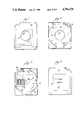
- FIG. 7 is an outside plan view of one portion of a 3480 tape cartridge
- FIG. 8 is an inside plan view of FIG. 7;
- FIG. 9 is an outside plan view of the other portion of a 3480 tape cartridge.
- FIG. 10 is an inside plan view of FIG. 9.
- FIG. 1 there is illustrated a jacket blank 2 of one modification of the invention.
- the jacket blank 2 has a flat sheet 4 of jacketing material having a generally rectangular portion 6 and three integral flaps 8, 10 and 12 extending outwardly from portions thereof.
- a generally rectangular flat liner 14 of a material having a low coefficient of friction is superposed over the generally rectangular portion 6 of the flat sheet 4 of jacketing material.
- the generally rectangular flat liner 14 is secured to the flat sheet 4 of jacketing material by suitable means, such as an adhesive.
- An electronic surveillance tag 16 is positioned between a portion of the flat sheet 4 of jacketing material and a portion of the generally rectangular flat liner 14.
- the electronic surveillance tag 16 is of a conventional nature and may comprise an inductive-capacitive circuit such as that marketed by Check-Point Incorporated.
- the electronic surveillance tag 16 is located in the upper central portion of the jacket blank 2.
- the electronic surveillance tag 16 may be secured to either the flat sheet 4 of jacketing material or the generally rectangular flat liner or to both by suitable means, such as an adhesive.
- Circular openings 30 and 32 are formed in the jacket blank 2 to provide for the exposure of the central portion of a floppy disk as described below.
- Oblong openings 34 and 36 are formed in the jacket blank 2 to provide for the exposure of the information portion of a floppy disk as described.
- Information openings 38 and 40 and 42 and 44 are also formed in the jacket blank 2.
- a closed jacket 46 having a floppy disk 48 enclosed therein, illustrated in FIG. 2, is formed by first folding the jacket blank 2 substantially in half around the fold line 50. Flaps 8 and 12 are then folded over portions of the flat sheet 4 of jacketing material and secured thereto by suitable means, such as an adhesive, to form a jacket. A floppy disk 48 is inserted into the jacket between portions of the generally rectangular liner 14. The flap 10 is then folded over portions of the flat sheet 4 of jacketing material and secured thereto by suitable means, such as an adhesive.
- the floppy disk 48 has a central portion 52 exposed through the circular openings 30 and 32 and adapted to be grasped by the drive means described below.
- the floppy disk 48 also has information means 54 exposed through the oblong openings 34 and 36.
- a conventional floppy disk drive means 56 is illustrated in FIG. 3.
- the drive means 56 is generally box-like and has a rectangular opening 58 in an end wall 60 through which a closed jacket 46 having a floppy disk 48 enclosed therein may be inserted.
- the drive means 56 has an electronic circuit, described below, mounted therein for detecting the presence or absence of an electronic surveillance tag 16.
- the purpose of the electronic circuit contained in the disk drive mechanism is to detect the special disk described herein.
- a conventional floppy disk drive is modified to contain an electronic circuit and a sense antenna which can detect the presence of the tag or circuit placed in the envelope for the magnetic disk media.
- the tag contains a resonant circuit which preferably is small and lossy. In the embodiment described, the tag circuit is designed to be resonant at preferably about 8 MHz.
- the circuit contained in the disk drive preferably contains an FM oscillator which is connected to an antenna (FIG. 6) which acts as the inductor in a resonant tank circuit.
- the other component of the tank circuit is a voltage variable capacitor or varactor.
- the FM oscillator can be made to oscillate preferably between 6 MHz and 10 MHz.
- the circuit also contains a second oscillator which preferably is designed to generate a triangular wave form at a frequency of about 2 kHz. This signal is used to drive the varactor in the FM oscillator, as shown in FIG. 6. As the triangle wave ramps up, as shown in FIG. 4, the FM oscillator frequency is increased and conversely the tank frequency decreases as the triangle wave ramps down. By this process, the frequency of the antenna varies directly and synchronously with the triangle wave form, shown in FIG. 6.
- AGC automatic gain control circuit
- the tag on the floppy disk when in proximity to the antenna inside the disk drive mechanism, and when scanned, places an additional load on the FM oscillator which in turn increases gain and increases the voltage signal.
- This signal processing design provides for synchronous rises in the AGC voltage which must be detected to verify the presence of a tag. Normally, such designs would employ several stages of differentiation in order to magnify the small voltage changes to detectable levels. Conventional designs, however, increase the the circuits' sensitivity to noise where the environment may produce incorrect signal responses.
- the present invention incorporates an amplifier 2 kHz with small gain. This first stage of differentiation between signals and noise is extremely important where the environment is characteristically noisy.
- the next level of discrimination in the present invention takes advantage of the fact that the circuit can be designed to identify the time when the tag-blip is expected to appear. This should happen at the time the point in the triangular wave corresponds to approximately the 8 MHz output of the FM Oscillator.
- a comparator connected to the triangle wave generator produces a timing signal, designated as OSC Window+, that indicates where the so-called tag-blip should be.
- a peak detector connected to the comparator looks for the highest amplitude blip during he time of this window (called peak A in FIG. 6).
- a second peak detector measures the highest peak during the rest of the triangular cycle; this is called peak B(also in FIG. 6).
- the highest peak A should be about the same as the highest peak B.
- a fixed offset is added to peak B.
- the final peak B should be larger than peak A.
- any noise will appear with equal probability as a signal in or out of the peak A window (OSC Window+, FIG. 6).
- Most noise is of a much higher frequency than 2 kHz, and will therefore be: (1) effectively filtered out of the resultant signal by the low bandwidth of the amplifier; or is (2), present in both the peak A window and the peak B window. If it is present in both windows, it is effectively cancelled out by the peak detectors.
- Noise present in the environment of the circuit may cause a mis-triggering of the comparator between peak A and peak B.
- the detector line in FIG. 5 will not show a signal a small percentage of the time.
- the gain and offset of peak A and peak B should be such that this happens at an infrequent rate. This rate may be as small as one in one hundred samples.
- an Integrating Filter shown in the block diagram in FIG. 6.
- This filter is designed such that approximately 10 correct samples are required for the final flip/flop to change state.
- the detector line would then have to report high for about 10 cycles of the 2 kHz triangular wave in order for the circuit to verify detection of the presence of the resonant circuit in the tag. Once detected, the detector line would have to be low for the same amount of time in order for the circuit to change back to a tag not detected state.
- this timed discrimination effectively filters out infrequent noise-induced errors.
- the final device in the circuit is the flip/flop circuit referred previously and designated as F/F in FIG. 6.
- This circuit is designed to provide set or reset signals to indicate the presence or absence of the tag in the disk drive according to the signals also previously described.
- This circuit selectively drives an output transistor whose collector is connected in series to the ground side of the write-protect sensor which is present in any disk drive. If the flip/flop circuit is in the set mode, the transistor allows the write-protect sensor to work normally. If, on the other hand, a tag is not detected, then the flip/flop circuit is retained in the reset mode by the transistor remaining in an high-impedance state, and the floppy drive remains in a write-protected mode. This provides protection against unauthorized entry into a protected system which will frustrate copying, alteration or any other activities which have not previously been authorized. Other outputs can be provided which would alert security personnel that unauthorized entry has been attempted.
- FIG. 7 there is illustrated the outer surface configuration 62 of one portion of a conventional 3480 tape cartridge and in FIG. 8, there is illustrated the inner surface configuration 64 of the same one portion.
- a plurality of curved inner partitions 66 provide means for properly locating the tape (not shown).
- a central opening 68 having a beveled sidewall 70 is provided in the one portion.
- Conventional means 72 are provided for cooperation with the tape in a conventional manner.
- FIG. 9 there is illustrated the outer surface configration 74 of the other portion of the conventional 3480 tape cartridge.
- the outer surface configuration 74 has a recessed area 76 in which is secured, by suitable means such as adhesive, an opaque indicia bearing label 78 containing information relating to the tape cartridge.
- FIG. 10 there is illustrated the inner surface oonfiguration 80 of the other portion of the tape cartridge.
- a plurality of curved inner portions 82 and a center stud 84 provide means for locating the tape.
- conventional means 86 are provided for cooperating with the conventional means 72 in a conventional manner.
- An electronic surveillance tag 16 is secured to the inner surface configuration 80 of the other portion.
- the electronic surveillance tag 16 is located within the borders of the opaque indicia bearing label 78 so that the electronic surveillance tag 16 is not visible when looking at the outer surface configuration 74. Also, the electronic surveillance tag 16 is within the border defined by the curved inner portions 66 and 82 so that the tape (not shown) prevents observance of the electronic surveillance tag 16 when looking at the outer surface 62.
- the electronic surveillance tag 16 is applied during the manufacture of the tape cartridge so that the electronic surveillance tag 16 is covertly secured in the 3480 tape cartridge as it is in the floppy disk. In the manufacturing process, an electronic surveillance tag 16 is secured on the inner surface configuration by suitable means, such as an adhesive, at a location as indicate in FIG. 10.
- a tape is inserted within the border defined by the curved inner portions 82.
- the one portion is then positioned over the other portion so that the inner surface configuration 64 and 80 are in a facing relationship.
- the one portion is then permanently secured to the other portion by suitable means, such as an adhesive, so that the tape cartridge may not be opened without detection.
- An electronic circuit such as that described above, in relation to FIGS. 4-6, will be provided in the computer drive mechanism used with the tape cartridge to detect the presence or absence of the electronic surveillance tag 16. If no electronic surveillance tag 16 is detected, the electronic circuit will prevent operation of the computer drive mechanism and produce a signal to alert security personnel.
Abstract
Description
Claims (15)
Priority Applications (4)
| Application Number | Priority Date | Filing Date | Title |
|---|---|---|---|
| US06/916,891 US4794470A (en) | 1986-06-25 | 1986-10-09 | Security system for protecting information |
| CA000540480A CA1286401C (en) | 1986-06-25 | 1987-06-25 | Security system for protecting information |
| EP87109141A EP0251210B1 (en) | 1986-06-25 | 1987-06-25 | A security system for protecting information |
| DE8787109141T DE3773545D1 (en) | 1986-06-25 | 1987-06-25 | SECURITY SYSTEM FOR PRIVACY. |
Applications Claiming Priority (2)
| Application Number | Priority Date | Filing Date | Title |
|---|---|---|---|
| US87832086A | 1986-06-25 | 1986-06-25 | |
| US06/916,891 US4794470A (en) | 1986-06-25 | 1986-10-09 | Security system for protecting information |
Related Parent Applications (1)
| Application Number | Title | Priority Date | Filing Date |
|---|---|---|---|
| US87832086A Continuation-In-Part | 1986-06-25 | 1986-06-25 |
Publications (1)
| Publication Number | Publication Date |
|---|---|
| US4794470A true US4794470A (en) | 1988-12-27 |
Family
ID=27128482
Family Applications (1)
| Application Number | Title | Priority Date | Filing Date |
|---|---|---|---|
| US06/916,891 Expired - Fee Related US4794470A (en) | 1986-06-25 | 1986-10-09 | Security system for protecting information |
Country Status (4)
| Country | Link |
|---|---|
| US (1) | US4794470A (en) |
| EP (1) | EP0251210B1 (en) |
| CA (1) | CA1286401C (en) |
| DE (1) | DE3773545D1 (en) |
Cited By (17)
| Publication number | Priority date | Publication date | Assignee | Title |
|---|---|---|---|---|
| US4910625A (en) * | 1988-10-11 | 1990-03-20 | Eastman Kodak Company | Article surveillance apparatus and systems for computer data disks |
| US5012380A (en) * | 1989-08-24 | 1991-04-30 | Eastman Kodak Company | Article surveillance protection of flexible magnetic computer data storage disks |
| WO1991006934A1 (en) * | 1989-10-31 | 1991-05-16 | Checkpoint Systems, Inc. | Method for tagging articles used in conjunction with an electronic article surveillance system, and tags or labels useful in connection therewith |
| US5081445A (en) * | 1991-03-22 | 1992-01-14 | Checkpoint Systems, Inc. | Method for tagging articles used in conjunction with an electronic article surveillance system, and tags or labels useful in connection therewith |
| US5185692A (en) * | 1991-05-30 | 1993-02-09 | Smith James D | Computer security device having connector with spring loaded contact members |
| US5253821A (en) * | 1992-03-02 | 1993-10-19 | Minnesota Mining And Manufacturing Company | Security magnetic tape cartridge for use in electronic article surveillance systems |
| US5347508A (en) * | 1992-04-22 | 1994-09-13 | Minnesota Mining And Manufacturing Company | Optical information storage disk for use with electronic article surveillance systems |
| WO1995010834A1 (en) * | 1993-10-12 | 1995-04-20 | Schiavone Vincent J | Method and apparatus for securing removable data storage media |
| US5528223A (en) * | 1994-09-27 | 1996-06-18 | Sensormatic Electronics Corporation | Video game cartridge including a security device and method of deterring theft of same |
| US5593025A (en) * | 1995-12-15 | 1997-01-14 | Display Technologies, Inc. | Foldable jewelry card |
| US5845195A (en) * | 1996-07-17 | 1998-12-01 | Miodownik; Saul | Digital radio frequency communications device for insertion into floppy diskette drive |
| US5867102A (en) * | 1997-02-27 | 1999-02-02 | Wallace Computer Services, Inc. | Electronic article surveillance label assembly and method of manufacture |
| US6100788A (en) * | 1997-12-29 | 2000-08-08 | Storage Technology Corporation | Multifunctional electromagnetic transponder device and method for performing same |
| US6614750B2 (en) | 2001-02-28 | 2003-09-02 | Warren Weber | Optical recordable disk security system |
| US6774782B2 (en) | 2001-04-27 | 2004-08-10 | Battelle Memorial Institute | Radio frequency personnel alerting security system and method |
| US20050232127A1 (en) * | 2002-07-08 | 2005-10-20 | Josephus Kahlman | Information carrier drive device provided with a double antenna |
| US20060007003A1 (en) * | 2003-02-14 | 2006-01-12 | Honda Motor Co., Ltd. | Motor vehicle mounted with ic tag and control system for the same |
Families Citing this family (4)
| Publication number | Priority date | Publication date | Assignee | Title |
|---|---|---|---|---|
| FR2633086B1 (en) * | 1988-06-20 | 1990-11-09 | Dupre Michel Jean | METHOD AND APPARATUS FOR DIGITAL DATA RECORDING, PROTECTED DATA RECORDING MEDIUM, AND APPARATUS FOR READING DATA RECORDED ON SUCH MEDIUM |
| DE4219695A1 (en) * | 1992-06-16 | 1993-12-23 | Compass Business Computer Gmbh | Protection apparatus for authorisation dependent computer use - has generator producing coded signal in form of output signal from data carrier e.g. diskette, concerned. |
| DE29605266U1 (en) * | 1996-03-21 | 1996-05-23 | Hsb Helmut Szynka Gmbh | Protection device |
| JP2001034468A (en) * | 1999-07-22 | 2001-02-09 | Sensor Technos Kk | Security system |
Citations (15)
| Publication number | Priority date | Publication date | Assignee | Title |
|---|---|---|---|---|
| US32296A (en) * | 1861-05-14 | Steering apparatus | ||
| US3967161A (en) * | 1972-06-14 | 1976-06-29 | Lichtblau G J | A multi-frequency resonant tag circuit for use with an electronic security system having improved noise discrimination |
| US4074249A (en) * | 1977-02-04 | 1978-02-14 | Knogo Corporation | Magnetic detection means |
| US4075618A (en) * | 1976-07-15 | 1978-02-21 | Minnesota Mining And Manufacturing Company | Magnetic asymmetric antipilferage marker |
| US4263634A (en) * | 1979-09-17 | 1981-04-21 | International Business Machines Corporation | Magnetic disk-jacket assembly |
| US4353064A (en) * | 1981-01-14 | 1982-10-05 | Honeywell Inc. | Battery operated access control card |
| DE3212039A1 (en) * | 1982-03-31 | 1983-10-06 | Esser Roland | Signalling device |
| US4471343A (en) * | 1977-12-27 | 1984-09-11 | Lemelson Jerome H | Electronic detection systems and methods |
| WO1985002696A1 (en) * | 1983-12-06 | 1985-06-20 | Alexander Battison Gardiner | Computer system |
| GB2154350A (en) * | 1984-02-17 | 1985-09-04 | Standard Telephones Cables Ltd | Preventing misuse of information stored on computer tapes and the like |
| US4555077A (en) * | 1983-11-25 | 1985-11-26 | Electronic Processors, Inc. | Tape cartridge |
| US4665387A (en) * | 1983-07-13 | 1987-05-12 | Knogo Corporation | Method and apparatus for target deactivation and reactivation in article surveillance systems |
| US4673923A (en) * | 1986-05-19 | 1987-06-16 | Checkpoint Systems, Inc. | Article surveillance using reactivatable resonant tags |
| US4691202A (en) * | 1984-04-03 | 1987-09-01 | Denne Phillip R M | Identification systems |
| US4692746A (en) * | 1986-02-26 | 1987-09-08 | Security Tag Systems, Inc. | Recording-tape-reel assembly with electronic tag |
Family Cites Families (4)
| Publication number | Priority date | Publication date | Assignee | Title |
|---|---|---|---|---|
| US3732465A (en) * | 1971-09-20 | 1973-05-08 | Walton C | Electronic sensing and actuator system |
| NL161904C (en) * | 1973-04-13 | Knogo Corp | THEFT DETECTION SYSTEM. | |
| US4106006A (en) * | 1976-01-26 | 1978-08-08 | Wagner Electric Corporation | Dual-frequency induction-keyed control circuit with keying network having variable resonant frequency |
| NL8202951A (en) * | 1982-07-21 | 1984-02-16 | Nedap Nv | ABSORPTION DETECTION SYSTEM. |
-
1986
- 1986-10-09 US US06/916,891 patent/US4794470A/en not_active Expired - Fee Related
-
1987
- 1987-06-25 CA CA000540480A patent/CA1286401C/en not_active Expired - Fee Related
- 1987-06-25 EP EP87109141A patent/EP0251210B1/en not_active Expired - Lifetime
- 1987-06-25 DE DE8787109141T patent/DE3773545D1/en not_active Expired - Fee Related
Patent Citations (15)
| Publication number | Priority date | Publication date | Assignee | Title |
|---|---|---|---|---|
| US32296A (en) * | 1861-05-14 | Steering apparatus | ||
| US3967161A (en) * | 1972-06-14 | 1976-06-29 | Lichtblau G J | A multi-frequency resonant tag circuit for use with an electronic security system having improved noise discrimination |
| US4075618A (en) * | 1976-07-15 | 1978-02-21 | Minnesota Mining And Manufacturing Company | Magnetic asymmetric antipilferage marker |
| US4074249A (en) * | 1977-02-04 | 1978-02-14 | Knogo Corporation | Magnetic detection means |
| US4471343A (en) * | 1977-12-27 | 1984-09-11 | Lemelson Jerome H | Electronic detection systems and methods |
| US4263634A (en) * | 1979-09-17 | 1981-04-21 | International Business Machines Corporation | Magnetic disk-jacket assembly |
| US4353064A (en) * | 1981-01-14 | 1982-10-05 | Honeywell Inc. | Battery operated access control card |
| DE3212039A1 (en) * | 1982-03-31 | 1983-10-06 | Esser Roland | Signalling device |
| US4665387A (en) * | 1983-07-13 | 1987-05-12 | Knogo Corporation | Method and apparatus for target deactivation and reactivation in article surveillance systems |
| US4555077A (en) * | 1983-11-25 | 1985-11-26 | Electronic Processors, Inc. | Tape cartridge |
| WO1985002696A1 (en) * | 1983-12-06 | 1985-06-20 | Alexander Battison Gardiner | Computer system |
| GB2154350A (en) * | 1984-02-17 | 1985-09-04 | Standard Telephones Cables Ltd | Preventing misuse of information stored on computer tapes and the like |
| US4691202A (en) * | 1984-04-03 | 1987-09-01 | Denne Phillip R M | Identification systems |
| US4692746A (en) * | 1986-02-26 | 1987-09-08 | Security Tag Systems, Inc. | Recording-tape-reel assembly with electronic tag |
| US4673923A (en) * | 1986-05-19 | 1987-06-16 | Checkpoint Systems, Inc. | Article surveillance using reactivatable resonant tags |
Cited By (18)
| Publication number | Priority date | Publication date | Assignee | Title |
|---|---|---|---|---|
| US4910625A (en) * | 1988-10-11 | 1990-03-20 | Eastman Kodak Company | Article surveillance apparatus and systems for computer data disks |
| US5012380A (en) * | 1989-08-24 | 1991-04-30 | Eastman Kodak Company | Article surveillance protection of flexible magnetic computer data storage disks |
| WO1991006934A1 (en) * | 1989-10-31 | 1991-05-16 | Checkpoint Systems, Inc. | Method for tagging articles used in conjunction with an electronic article surveillance system, and tags or labels useful in connection therewith |
| US5081445A (en) * | 1991-03-22 | 1992-01-14 | Checkpoint Systems, Inc. | Method for tagging articles used in conjunction with an electronic article surveillance system, and tags or labels useful in connection therewith |
| US5185692A (en) * | 1991-05-30 | 1993-02-09 | Smith James D | Computer security device having connector with spring loaded contact members |
| US5253821A (en) * | 1992-03-02 | 1993-10-19 | Minnesota Mining And Manufacturing Company | Security magnetic tape cartridge for use in electronic article surveillance systems |
| US5347508A (en) * | 1992-04-22 | 1994-09-13 | Minnesota Mining And Manufacturing Company | Optical information storage disk for use with electronic article surveillance systems |
| WO1995010834A1 (en) * | 1993-10-12 | 1995-04-20 | Schiavone Vincent J | Method and apparatus for securing removable data storage media |
| US5528223A (en) * | 1994-09-27 | 1996-06-18 | Sensormatic Electronics Corporation | Video game cartridge including a security device and method of deterring theft of same |
| US5593025A (en) * | 1995-12-15 | 1997-01-14 | Display Technologies, Inc. | Foldable jewelry card |
| US5845195A (en) * | 1996-07-17 | 1998-12-01 | Miodownik; Saul | Digital radio frequency communications device for insertion into floppy diskette drive |
| US5867102A (en) * | 1997-02-27 | 1999-02-02 | Wallace Computer Services, Inc. | Electronic article surveillance label assembly and method of manufacture |
| US6100788A (en) * | 1997-12-29 | 2000-08-08 | Storage Technology Corporation | Multifunctional electromagnetic transponder device and method for performing same |
| US6614750B2 (en) | 2001-02-28 | 2003-09-02 | Warren Weber | Optical recordable disk security system |
| US6774782B2 (en) | 2001-04-27 | 2004-08-10 | Battelle Memorial Institute | Radio frequency personnel alerting security system and method |
| US20050232127A1 (en) * | 2002-07-08 | 2005-10-20 | Josephus Kahlman | Information carrier drive device provided with a double antenna |
| US20060007003A1 (en) * | 2003-02-14 | 2006-01-12 | Honda Motor Co., Ltd. | Motor vehicle mounted with ic tag and control system for the same |
| US7764173B2 (en) * | 2003-02-14 | 2010-07-27 | Honda Motor Co., Ltd. | IC tag equipped vehicle and management system thereof |
Also Published As
| Publication number | Publication date |
|---|---|
| CA1286401C (en) | 1991-07-16 |
| EP0251210B1 (en) | 1991-10-09 |
| EP0251210A1 (en) | 1988-01-07 |
| DE3773545D1 (en) | 1991-11-14 |
Similar Documents
| Publication | Publication Date | Title |
|---|---|---|
| US4794470A (en) | Security system for protecting information | |
| US5739754A (en) | Circuit antitheft and disabling mechanism | |
| US4692746A (en) | Recording-tape-reel assembly with electronic tag | |
| US6264108B1 (en) | Protection of sensitive information contained in integrated circuit cards | |
| EP0550443B1 (en) | Security tag for compact disc storage container | |
| US4910625A (en) | Article surveillance apparatus and systems for computer data disks | |
| EP0417447A2 (en) | Data protection by detection of intrusion into electronic assemblies | |
| WO1998010386A9 (en) | Disc-like device with eas material | |
| WO1989009984A1 (en) | Antipilferage tags and their use | |
| US5012380A (en) | Article surveillance protection of flexible magnetic computer data storage disks | |
| US6614750B2 (en) | Optical recordable disk security system | |
| EP1067496A2 (en) | Security device and method for detecting the unauthorized opening of containers | |
| EP0786696B1 (en) | Method for protecting a magnetic layer on photosensitive material | |
| US5253821A (en) | Security magnetic tape cartridge for use in electronic article surveillance systems | |
| US5940362A (en) | Disc device having a magnetic layer overweighing the information signal pattern for electronic article surveillance | |
| CN102985630B (en) | For the safety battery cabin of hard label of reporting to the police | |
| US7015790B1 (en) | Intelligent antitheft method and system combining magnetic tags and smart cards | |
| EP1063623A1 (en) | Self-sounding commodities monitoring device | |
| JPS6366783A (en) | Safety apparatus for protection of information | |
| JP2667498B2 (en) | Activation / deactivation method of product monitoring system, case and detected means | |
| US6394022B1 (en) | Triboluminescent tamper-indicating device | |
| CN111243149A (en) | EM + RFID-based area control system and anti-theft method of access control system thereof | |
| JPH082869Y2 (en) | Security sensor container | |
| JPH1139838A (en) | Magnetic memory-protecting apparatus | |
| KR100495072B1 (en) | Materials security system |
Legal Events
| Date | Code | Title | Description |
|---|---|---|---|
| AS | Assignment |
Owner name: MEDIA SECURITY INCORPORATED AND ASSOCIATES, COLORA Free format text: ASSIGNMENT OF ASSIGNORS INTEREST.;ASSIGNORS:LAUFFENBURGER, JAMES H.;DENEHY, GEORGE F.;NOVICKIS, ANDRE;REEL/FRAME:004668/0454 Effective date: 19861007 Owner name: MEDIA SECURITY INCORPORATED AND ASSOCIATES, A CORP Free format text: ASSIGNMENT OF ASSIGNORS INTEREST;ASSIGNORS:LAUFFENBURGER, JAMES H.;DENEHY, GEORGE F.;NOVICKIS, ANDRE;REEL/FRAME:004668/0454 Effective date: 19861007 |
|
| AS | Assignment |
Owner name: BOETTCHER VENTURE CAPITAL PARTNERS, L.P., Free format text: ASSIGNMENT OF ASSIGNORS INTEREST.;ASSIGNOR:MEDIA SECURITY INCORPORATED;REEL/FRAME:004988/0982 Effective date: 19881212 Owner name: KALIKAS, GREGORY Free format text: ASSIGNMENT OF ASSIGNORS INTEREST.;ASSIGNOR:MEDIA SECURITY INCORPORATED;REEL/FRAME:004988/0982 Effective date: 19881212 Owner name: FBS SMALL BUSINESS INVESTMENT COMPANY, LIMITED PAR Free format text: ASSIGNMENT OF ASSIGNORS INTEREST.;ASSIGNOR:MEDIA SECURITY INCORPORATED;REEL/FRAME:004988/0982 Effective date: 19881212 |
|
| CC | Certificate of correction | ||
| REMI | Maintenance fee reminder mailed | ||
| FPAY | Fee payment |
Year of fee payment: 4 |
|
| SULP | Surcharge for late payment | ||
| REMI | Maintenance fee reminder mailed | ||
| LAPS | Lapse for failure to pay maintenance fees | ||
| FP | Lapsed due to failure to pay maintenance fee |
Effective date: 19970101 |
|
| STCH | Information on status: patent discontinuation |
Free format text: PATENT EXPIRED DUE TO NONPAYMENT OF MAINTENANCE FEES UNDER 37 CFR 1.362 |