US4784643A - Detector of air bubbles in a circuit of liquid - Google Patents

Detector of air bubbles in a circuit of liquid Download PDF

Info

Publication number
US4784643A
US4784643A US07/054,968 US5496887A US4784643A US 4784643 A US4784643 A US 4784643A US 5496887 A US5496887 A US 5496887A US 4784643 A US4784643 A US 4784643A
Authority
US
United States
Prior art keywords
emitter
detector
liquid
receiver
circuit
Prior art date
Legal status (The legal status is an assumption and is not a legal conclusion. Google has not performed a legal analysis and makes no representation as to the accuracy of the status listed.)
Expired - Fee Related
Application number
US07/054,968
Inventor
Roman Siretchi
Pierre Vignacq
Current Assignee (The listed assignees may be inaccurate. Google has not performed a legal analysis and makes no representation or warranty as to the accuracy of the list.)
AONYME MMS ZONE INDUSNOR -LOTISSEMENT DE 1'ECHANGEUR- 64000 PAU (FRANCE) A FRENCH CORP Ste
MMS SA
Original Assignee
MMS SA
Priority date (The priority date is an assumption and is not a legal conclusion. Google has not performed a legal analysis and makes no representation as to the accuracy of the date listed.)
Filing date
Publication date
Application filed by MMS SA filed Critical MMS SA
Assigned to SOCIETE AONYME, M.M.S., ZONE INDUSNOR -LOTISSEMENT DE 1'ECHANGEUR- 64000 PAU (FRANCE), A FRENCH CORP. reassignment SOCIETE AONYME, M.M.S., ZONE INDUSNOR -LOTISSEMENT DE 1'ECHANGEUR- 64000 PAU (FRANCE), A FRENCH CORP. ASSIGNMENT OF ASSIGNORS INTEREST. Assignors: SIRETCHI, ROMAN, VIGNACQ, PIERRE
Application granted granted Critical
Publication of US4784643A publication Critical patent/US4784643A/en
Anticipated expiration legal-status Critical
Expired - Fee Related legal-status Critical Current

Links

Images

Classifications

    • GPHYSICS
    • G01MEASURING; TESTING
    • G01PMEASURING LINEAR OR ANGULAR SPEED, ACCELERATION, DECELERATION, OR SHOCK; INDICATING PRESENCE, ABSENCE, OR DIRECTION, OF MOVEMENT
    • G01P13/00Indicating or recording presence, absence, or direction, of movement
    • G01P13/008Indicating or recording presence, absence, or direction, of movement by using a window mounted in the fluid carrying tube
    • G01P13/0086Indicating or recording presence, absence, or direction, of movement by using a window mounted in the fluid carrying tube with photo-electric detection
    • AHUMAN NECESSITIES
    • A61MEDICAL OR VETERINARY SCIENCE; HYGIENE
    • A61MDEVICES FOR INTRODUCING MEDIA INTO, OR ONTO, THE BODY; DEVICES FOR TRANSDUCING BODY MEDIA OR FOR TAKING MEDIA FROM THE BODY; DEVICES FOR PRODUCING OR ENDING SLEEP OR STUPOR
    • A61M5/00Devices for bringing media into the body in a subcutaneous, intra-vascular or intramuscular way; Accessories therefor, e.g. filling or cleaning devices, arm-rests
    • A61M5/36Devices for bringing media into the body in a subcutaneous, intra-vascular or intramuscular way; Accessories therefor, e.g. filling or cleaning devices, arm-rests with means for eliminating or preventing injection or infusion of air into body
    • A61M5/365Air detectors

Definitions

  • the present invention relates to an air bubble detector or, more generally, to a detector of liquid discontinuity in a circuit of liquid. More particularly, the invention relates to an air bubble detector, of the type comprising photoemissive means and photoreceptor means adapted to be placed on two opposite sides of a conduit carrying the liquid, and means for processing the signals produced by the photoreceptor means in order to produce an information signal in response to the appearance of an air bubble or a discontinuity of liquid in the conduit at the detector level.
  • the invention is particularly, but not exclusively, applicable to the detection of air bubbles in a circuit of liquid in parenteral nutrition or blood transfusion systems, as well as to bottle-empty detection in such systems.
  • the liquid supplied from a bottle is injected into a patient by means of a pump.
  • Air may be introduced into the circuit of liquid, for example if the pump continues to work when the bottle is empty, or through a leak in the parenteral perfusion or transfusion tube due to the exerted pumping forces. Because of the danger that they represent for the patient, the air bubbles must be detected.
  • some are of optical type with a photo-emitter and a photo-receptor, disposed in facing relationship on two opposite sides of a conduit in transparent material carrying the liquid.
  • the passage of an air bubble causes a variation in the transparency of the medium situated between the photo-emitter and the photo-receptor, hence a variation which can be detected from a signal supplied by the photo-detector.
  • the photo-emissive and photo-receptor means comprise first and second optical emitter-receiver pairs designed to be placed apart one from the other along a conduit, and a regulator circuit operationally coupled to each emitter-receiver pair for controlling the operation of said pair inside a maximum response range, independently of the transparency of the liquid, said regulator circuit being so arranged as to supply the emitter with a voltage which is a function of the difference between a voltage supplied by the receiver and a reference voltage, and
  • the processing means comprise a differential circuit, arranged so as to produce a differential signal representing the difference between the signals produced by the receivers and a comparator circuit connected to the differential circuit in order to supply or not, an informative signal as a function of the differential signal.
  • the detector according to the invention can be used to detect air bubbles in a conduit carrying a liquid, as well as to detect that a reservoir or bottle supplying a circuit of liquid is empty, emptying of the conduit on which the detector is mounted being, for said detector, equivalent to the appearance of an air bubble.
  • the detector according to the invention can be used, in particular, for detecting when a bottle is empty in perfusion and transfusion systems.
  • the detector according to the invention offers many advantages over the known bottle-empty detectors.
  • the latter are generally optical type devices designed to monitor the flow of the liquid in the drip chamber; the detector is energized every time a drop passes and a bottle-empty alarm signal is given when the time interval between two drops exceeds a predetermined threshold.
  • the system is then sensitive to the liquid supply flow since the frequency of the drops varies with the flow rate.
  • positioning of the detector with respect to the drip chamber is not precise and readily disturbed.
  • the emitter and receiver are relatively far apart since the drip chamber has a diameter of several centimeters, hence the possibility of unwanted conditions due to changes in the environment lighting (sunlight, artificial light, etc.).
  • FIGURE is a diagram of one embodiment of the detector according to the invention.
  • the detector according to the invention is operationally coupled to a conduit or tube, such as for example a tube forming part of a parenteral nutrition or blood transfusion system in which the liquid is administered to a patient by means of a pump, such as a peristaltic-type pump.
  • a pump such as a peristaltic-type pump.
  • the detector is then placed on a tube situated downstream of said pump.
  • the detector comprises two optical emitter-receiver pairs, E1-R1 and E2-R2 respectively.
  • the emitter E1, E2 and the corresponding receiver R1, R2 are placed in facing relationship, on either side of tube T, outside of and close to the transparent wall thereof.
  • the two pairs E1-R1, E2-R2 are separated by a distance for example equal to a few millimeters.
  • Emitters E1, E2 are for example light emitting diodes emitting in infra-red, whereas receivers R1, R2 are phototransistors sensitive to the radiations emitted by said diodes.
  • the emitter-collector circuit of each transsistor R1, R2 is series-connected with a resistor r1, r2 between the ground and a terminal of voltage V+ of a supply source. Voltages U1, U2 drawn between the ground and the collectors of transistors R1, R2 constitute the output signals thereof, the amplitude of which signals varies as a function of the intensity of the received light.
  • Diodes E1, E2 are supplied with voltages Ua, Ub from differential amplifiers A1, A2. Said amplifiers A1, A2 have their negative inputs connected with a terminal of reference voltage level Uref, their positive inputs being connected to the collectors of transistors R1, R2 to receive voltages U1, U2 respectively.
  • Voltages Ua and Ub are also applied to the positive and negative inputs of a differential amplifier A3 which delivers a differential signal Uo. Said latter is applied to the input of an analog memory M, such as a capacitor circuit, for storing the amplitude of the differential signal Uo in response to the application of a control signal on a storage control input E in memory M.
  • the differential signal Uo is applied continuously on an input of a comparator A4, of which the other input receives the stored value Um of signal Uo outputted from memory M.
  • Comparator A4 delivers an alarm signal Sa when the difference between signals Uo and Um exceeds a predetermined threshold.
  • a digital-type memory M can be used.
  • the signal Uo is converted to digital form at the output of amplifier A3, and comparator A4 is in digital circuit form.
  • Differential amplifier A3 supplies a differential signal Uo which is proportional to the difference between signals Ua and Ub, hence representative of the difference between voltages U1 and U2.
  • emitter-receiver pairs or amplifiers A1, A2 with identical characteristics since the air bubble detection is achieved by monitoring the amplitude variations of signal Uo and not by comparing the instant absolute value of said signal with a threshold value.
  • the value of signal Uo is stored in memory M by sending a storage control signal on input E.
  • the stored value Um is used a reference value to detect a variation of instant signal Uo which is such that the difference Uo-Um exceeds a predetermined threshold. Such a variation will then be ascribed to the presence of an air bubble and will cause the triggering of an alarm signal.
  • the detector can also be used for detecting the emptiness of a bottle in a perfusion or transfusion system.
  • the emptying of the tube at detector level is equivalent to the passage of an air bubble.
  • the detector then has to be placed on a tube downstream of the bottom and upstream of the drip chamber.

Abstract

First and second spaced apart optical emitter-receiving pairs are located along a liquid carrying conduit. A regulator circuit is coupled to each emitter-receiver pair to control the operation of that pair inside a maximum response range regardless of the transparency of the liquid. The regulator circuit is so arranged as to supply the emitter with a voltage which is a function of the difference between a voltage supplied by the receiver portion of an optical-receiver pair and a reference voltage. A differential circuit produces a differential signal representing the difference between the signals produced by the receiver portions of the optical emitter-receiver pairs and a comparator circuit is connected to the differential circuit in order to generate an alarm signal as a function of the differential signal. The detector is particularly useful as an air bubble detector in a transfusion or perfusion system, and can also provide a container-empty alarm in such systems.

Description

FIELD OF THE INVENTION
The present invention relates to an air bubble detector or, more generally, to a detector of liquid discontinuity in a circuit of liquid. More particularly, the invention relates to an air bubble detector, of the type comprising photoemissive means and photoreceptor means adapted to be placed on two opposite sides of a conduit carrying the liquid, and means for processing the signals produced by the photoreceptor means in order to produce an information signal in response to the appearance of an air bubble or a discontinuity of liquid in the conduit at the detector level.
The invention is particularly, but not exclusively, applicable to the detection of air bubbles in a circuit of liquid in parenteral nutrition or blood transfusion systems, as well as to bottle-empty detection in such systems.
BACKGROUND OF THE INVENTION
In parenteral nutrition or blood transfusion systems, the liquid supplied from a bottle is injected into a patient by means of a pump. Air may be introduced into the circuit of liquid, for example if the pump continues to work when the bottle is empty, or through a leak in the parenteral perfusion or transfusion tube due to the exerted pumping forces. Because of the danger that they represent for the patient, the air bubbles must be detected.
The use of an air bubble detector, incorporated in the perfusion or transfusion tube, is impossible from a practical and economical standpoint. Indeed, the tube must be sterilizable as well as readily dismountable and re-assembled; in addition, the detector must not transmit any electrical current to the patient's body via the liquid which may be very conducting; finally, the tube being a consumer good, its cost must remain as low as possible.
It is therefore important to use air bubble detectors which are external to the perfusion or transfusion line, which makes the detection rather difficult, all the more so that the liquids can be of very varied types with completely different characteristics.
Among the known air bubble detectors, some are of optical type with a photo-emitter and a photo-receptor, disposed in facing relationship on two opposite sides of a conduit in transparent material carrying the liquid. The passage of an air bubble causes a variation in the transparency of the medium situated between the photo-emitter and the photo-receptor, hence a variation which can be detected from a signal supplied by the photo-detector.
Use of these known detectors raised difficulties due to the very wide dispersion of the transparency of the liquids normally carried in the conduit; transparent, translucid or opalescent liquids.
In order to overcome these difficulties, it has been proposed to use air bubble detectors of optical type in which the reference value, as a function of which the variation of the signal produced by the photo-detector is analyzed, is pre-adjusted manually. But, the detector adjusted in this way, is only capable of operating correctly inside a limited range of liquid transparency. Moreover, an error of adjustment may always occur, with serious consequences.
It has also been proposed in French patent application No. 2 361 644, to use a plurality of optical emitter-receiver pairs, one of which is used to make an automatic adjustment or pre-conditioning of the detector, making a distinction between transparent liquid and opaque liquid. The fact remains that, for every system of operation ("transparent" liquid or "opaque" liquid) the range of transparency remains wide, which always makes it difficult to select a reference value. Moreover, this automatic adjustment can be performed at the cost of a rather great complexity of the detector.
SUMMARY OF THE INVENTION
It is therefore the object of the invention to propose an air bubble or liquid discontinuity detector capable of working reliably within a wide range of liquid transparency, without the need of making any adjustment as a function of the liquid used, and with a structure which is kept relatively simple.
This object is reached with a detector of the type defined at the start of the present description and in which, according to the invention:
the photo-emissive and photo-receptor means comprise first and second optical emitter-receiver pairs designed to be placed apart one from the other along a conduit, and a regulator circuit operationally coupled to each emitter-receiver pair for controlling the operation of said pair inside a maximum response range, independently of the transparency of the liquid, said regulator circuit being so arranged as to supply the emitter with a voltage which is a function of the difference between a voltage supplied by the receiver and a reference voltage, and
the processing means comprise a differential circuit, arranged so as to produce a differential signal representing the difference between the signals produced by the receivers and a comparator circuit connected to the differential circuit in order to supply or not, an informative signal as a function of the differential signal.
The combination of the differential detection with the automatic control of the sensitivity at its maximum value makes it possible here to work inside a wide range of liquid transparency, in the best possible conditions, and without requiring any special pre-adjustment as a function of said transparency. The result is a greater reliability of operation of the air bubble detector, which is particularly important in an application to perfusion or transfusion systems.
In addition, the detector according to the invention can be used to detect air bubbles in a conduit carrying a liquid, as well as to detect that a reservoir or bottle supplying a circuit of liquid is empty, emptying of the conduit on which the detector is mounted being, for said detector, equivalent to the appearance of an air bubble.
Thus, the detector according to the invention can be used, in particular, for detecting when a bottle is empty in perfusion and transfusion systems. In this particular application, the detector according to the invention offers many advantages over the known bottle-empty detectors. The latter are generally optical type devices designed to monitor the flow of the liquid in the drip chamber; the detector is energized every time a drop passes and a bottle-empty alarm signal is given when the time interval between two drops exceeds a predetermined threshold. However, the system is then sensitive to the liquid supply flow since the frequency of the drops varies with the flow rate. Moreover, positioning of the detector with respect to the drip chamber is not precise and readily disturbed. Also, the emitter and receiver are relatively far apart since the drip chamber has a diameter of several centimeters, hence the possibility of unwanted conditions due to changes in the environment lighting (sunlight, artificial light, etc.). The use of a detector according to the invention, at the level of the conduit supplying the drip chamber, eliminates all the aforesaid drawbacks: detection is insensitive to the flow rate and to the nature of the fluid, and it is not affected by any changes in the ambient lighting since the distance between the associated emitter and receiver is only of a few millimeters.
BRIEF DESCRIPTION OF THE DRAWING
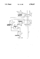
The invention will be more readily understood on reading the following description with reference to the accompanying drawing, in which the one and only FIGURE is a diagram of one embodiment of the detector according to the invention.
DETAILED DESCRIPTION OF A PREFERRED EMBODIMENT
As illustrated in the FIGURE, the detector according to the invention is operationally coupled to a conduit or tube, such as for example a tube forming part of a parenteral nutrition or blood transfusion system in which the liquid is administered to a patient by means of a pump, such as a peristaltic-type pump. The detector is then placed on a tube situated downstream of said pump.
The detector comprises two optical emitter-receiver pairs, E1-R1 and E2-R2 respectively. In each pair, the emitter E1, E2 and the corresponding receiver R1, R2 are placed in facing relationship, on either side of tube T, outside of and close to the transparent wall thereof. The two pairs E1-R1, E2-R2 are separated by a distance for example equal to a few millimeters.
The pairs E1-R1 and E2-R2 are preferably identical. Emitters E1, E2 are for example light emitting diodes emitting in infra-red, whereas receivers R1, R2 are phototransistors sensitive to the radiations emitted by said diodes. The emitter-collector circuit of each transsistor R1, R2 is series-connected with a resistor r1, r2 between the ground and a terminal of voltage V+ of a supply source. Voltages U1, U2 drawn between the ground and the collectors of transistors R1, R2 constitute the output signals thereof, the amplitude of which signals varies as a function of the intensity of the received light.
Diodes E1, E2 are supplied with voltages Ua, Ub from differential amplifiers A1, A2. Said amplifiers A1, A2 have their negative inputs connected with a terminal of reference voltage level Uref, their positive inputs being connected to the collectors of transistors R1, R2 to receive voltages U1, U2 respectively.
Voltages Ua and Ub are also applied to the positive and negative inputs of a differential amplifier A3 which delivers a differential signal Uo. Said latter is applied to the input of an analog memory M, such as a capacitor circuit, for storing the amplitude of the differential signal Uo in response to the application of a control signal on a storage control input E in memory M. In parallel, the differential signal Uo is applied continuously on an input of a comparator A4, of which the other input receives the stored value Um of signal Uo outputted from memory M. Comparator A4 delivers an alarm signal Sa when the difference between signals Uo and Um exceeds a predetermined threshold.
As a variant, a digital-type memory M can be used. In this case, the signal Uo is converted to digital form at the output of amplifier A3, and comparator A4 is in digital circuit form.
The detector described hereinabove works as follows:
In every emitter-receiver pair, when the transparency of the liquid varies, a corresponding variation of the voltage supplied by the phototransistor occurs, which variation results in a modification of the voltage applied to the light emitting diode, i.e. a modification of the emitting energy. For example, if the transparency diminishes, the amplitude of the signal produced by the phototransistor reduces, but the diode supply voltage increases due to an increase in the difference between the reference voltage Uref and the voltage supplied by the phototransistor. It becomes possible then to keep the phototransistor working inside a linear range of maximum sensitivity in order to preserve an optimum detection sensitivity. In other words, feedback of the signal supplied by each detector on an input of the differential amplifier which supplies the voltage to the corresponding emitter, enables the control of the response of the emitter-receiver pair in order to keep its sensitivity to the maximum value.
Differential amplifier A3 supplies a differential signal Uo which is proportional to the difference between signals Ua and Ub, hence representative of the difference between voltages U1 and U2.
In the absence of air bubbles in tube T, the transparencies of the media situated in the fields of action of the emitter-receiver pairs are identical. Signal Uo has a low if not nil amplitude. If the emitter-receiver pairs on the one hand, and amplifiers A1 and A2 on the other hand, have identical or very close characteristics, the appearance of an air bubble at the level of an emitter-receiver pair will therefore cause an important increase in the amplitude of signal Uo in absolute value.
However, it is not really necessary to have emitter-receiver pairs or amplifiers A1, A2 with identical characteristics since the air bubble detection is achieved by monitoring the amplitude variations of signal Uo and not by comparing the instant absolute value of said signal with a threshold value.
Thus, after a predetermined interval following the detector start-of-operation, such as for example around ten seconds, the value of signal Uo is stored in memory M by sending a storage control signal on input E. Throughout the remainder of the operation, the stored value Um is used a reference value to detect a variation of instant signal Uo which is such that the difference Uo-Um exceeds a predetermined threshold. Such a variation will then be ascribed to the presence of an air bubble and will cause the triggering of an alarm signal.
As already indicated, the detector can also be used for detecting the emptiness of a bottle in a perfusion or transfusion system. In this case, the emptying of the tube at detector level is equivalent to the passage of an air bubble. The detector then has to be placed on a tube downstream of the bottom and upstream of the drip chamber.
The invention is not in any way limited to the description given hereinabove, and on the contrary covers any modification that can be brought thereto without departing from its scope.

Claims (4)

What is claimed is:
1. A detector for detecting air bubbles or other liquid discontinuities in a circuit of liquid, comprising:
first and second spaced apart optical emitter-receiver pairs spaced apart from each other along a conduit carrying said liquid, each emitter-receiver pair comprising a light emitting means and a light receiving means placed in a facing relationship on opposite sides of said conduit;
a regulating circuit having a first input connected to said light receiving means, a second input of said regulating circuit connected to a source of a reference voltage and an output of said regulating circuit connected to said light emitting means in order to supply said light emitting means with a voltage which is a function of the difference between a voltage supplied by said light receiving means and said reference voltage such that said emitter-receiver pairs operate throughout a predetermined response range, independently of transparency of said liquid;
processing means comprising a differential circuit including first and second inputs connected to said first and second emitter-receiver pair, respectively, in order to produce a differential signal representative of the difference between a first voltage supplied by said light receiving means in said first emitter-receiver pair and a second voltage supplied by said light receiving means in said second emitter-receiver pair; and
said processing means operative to generate an alarm signal upon the appearance of an air bubble or liquid discontinuity in said conduit as a function of said differential signal.
2. The detector of claim 1, wherein said differential signal is proportional to the difference between the voltage supplied to said light emitting means in said first-emitter-receiver pair and the voltage supplied to said light emitting means in said second emitter-receiver pair.
3. The detector of claim 1, wherein said processing means further comprises value storage means connected to said differential circuit for storing the value of the differential signal at a given time, and further comprises a comparator circuit having inputs connected to said differential circuit and said value storage means, respectively, in order to generate said alarm signal when the difference between the current value and the stored value of said differential signal exceeds a predetermined threshold level.
4. The detector of claim 1, wherein said first and second optical emitter-receiver means, spaced apart one from the other along said conduit are located downstream from a container placed in-line with said conduit in a perfusion or transfusion installation in order to generate said alarm signal when said container becomes empty.
US07/054,968 1986-05-28 1987-05-28 Detector of air bubbles in a circuit of liquid Expired - Fee Related US4784643A (en)

Applications Claiming Priority (2)

Application Number Priority Date Filing Date Title
FR8607657A FR2599496B1 (en) 1986-05-28 1986-05-28 BUBBLE DETECTOR IN A LIQUID CIRCUIT
FR8607657 1986-05-28

Publications (1)

Publication Number Publication Date
US4784643A true US4784643A (en) 1988-11-15

Family

ID=9335745

Family Applications (1)

Application Number Title Priority Date Filing Date
US07/054,968 Expired - Fee Related US4784643A (en) 1986-05-28 1987-05-28 Detector of air bubbles in a circuit of liquid

Country Status (5)

Country Link
US (1) US4784643A (en)
EP (1) EP0248719B1 (en)
AT (1) ATE65700T1 (en)
DE (1) DE3771785D1 (en)
FR (1) FR2599496B1 (en)

Cited By (25)

* Cited by examiner, † Cited by third party
Publication number Priority date Publication date Assignee Title
US4857050A (en) * 1987-09-23 1989-08-15 Fisher Scientific Company Ratiometric air-in-line detector
US4981467A (en) * 1990-02-27 1991-01-01 Baxter International Inc. Apparatus and method for the detection of air in fluid delivery systems
US5232439A (en) * 1992-11-02 1993-08-03 Infusion Technologies Corporation Method for pumping fluid from a flexible, variable geometry reservoir
GB2266594A (en) * 1992-04-30 1993-11-03 Snecma Device for the detection of a leak in an oil/fuel heat exchanger.
US5382232A (en) * 1992-03-13 1995-01-17 Ivac Corporation Infusion system with air-in-line clear function
US5399171A (en) * 1991-06-10 1995-03-21 Baxter International Inc. Intravenous metering monitoring device
US5824881A (en) * 1996-09-13 1998-10-20 Cobe Laboratories Gas/fluid detector for contained fluid systems
US5868710A (en) * 1996-11-22 1999-02-09 Liebel Flarsheim Company Medical fluid injector
US5960129A (en) * 1997-12-22 1999-09-28 Bayer Corporation Method and apparatus for detecting liquid and gas segment flow through a tube
US6070761A (en) * 1997-08-22 2000-06-06 Deka Products Limited Partnership Vial loading method and apparatus for intelligent admixture and delivery of intravenous drugs
US6083206A (en) * 1994-12-07 2000-07-04 Midex Marketing Limited Intravenous infusion flow rate monitoring device
US6529751B1 (en) 1997-04-29 2003-03-04 Medtronic, Inc. Optical detection and quantification of microair in blood
US6616633B1 (en) 1997-09-19 2003-09-09 Alaris Medical Systems, Inc. Apparatus and method for air-in-line detection
US20050027253A1 (en) * 2003-07-29 2005-02-03 Thomas Castellano Sheath with air trap
US20050224523A1 (en) * 2004-04-13 2005-10-13 Advanced Technology Materials, Inc. Liquid dispensing method and system with headspace gas removal
US7004924B1 (en) * 1998-02-11 2006-02-28 Nxstage Medical, Inc. Methods, systems, and kits for the extracorporeal processing of blood
US20080237283A1 (en) * 2007-03-30 2008-10-02 Honda Motor Co., Ltd. Vehicular canister attachment structure
US20090097029A1 (en) * 2007-10-11 2009-04-16 Ecolab Inc. Optical product detection sensor
US20090262351A1 (en) * 2007-10-11 2009-10-22 Ecolab Inc. Optical product detection sensor
US20100133292A1 (en) * 2006-06-13 2010-06-03 Advanced Technology Materials, Inc. Liquid dispensing systems encompassing gas removal
US9078981B2 (en) 2012-09-21 2015-07-14 Boston Scientific Scimed Inc. Catheter system including an embolism protection device
US20150276804A1 (en) * 2014-03-31 2015-10-01 Minebea Co., Ltd. Detection device
CN105388097A (en) * 2014-08-21 2016-03-09 雅玛信过滤器株式会社 measurement device
US10072962B2 (en) * 2016-07-05 2018-09-11 Ecolab Usa Inc. Liquid out-of-product alarm system and method
US11389586B2 (en) 2016-09-06 2022-07-19 Roche Diabetes Care, Inc. Supervision device for ambulatory infusion

Families Citing this family (5)

* Cited by examiner, † Cited by third party
Publication number Priority date Publication date Assignee Title
DE4013402C2 (en) * 1990-04-26 1994-03-24 Infurex Ag Cham Method and device for detecting gas bubbles in a line filled with liquid, in particular a flexible, tubular line or a container
JP2539126Y2 (en) * 1991-08-26 1997-06-25 東亜医用電子株式会社 Sample suction monitoring device with automatic adjustment function
FR2691258A1 (en) * 1992-05-13 1993-11-19 Debiotech Device for detecting bubbles in a liquid flowing in a pipe.
CH692570A5 (en) * 1997-12-05 2002-08-15 Peter F Meier Apparatus for monitoring a catheter device.
AU2008200865B2 (en) 2007-03-30 2010-03-18 Honda Motor Co., Ltd. Motocycle front lighting apparatus structure

Citations (3)

* Cited by examiner, † Cited by third party
Publication number Priority date Publication date Assignee Title
US4447191A (en) * 1981-12-15 1984-05-08 Baxter Travenol Laboratories, Inc. Control circuit for a blood fractionation apparatus
US4525163A (en) * 1982-08-06 1985-06-25 Nuvatec, Inc. Intravenous set flow control device
US4673927A (en) * 1984-10-31 1987-06-16 Hospal A.G. Apparatus for detecting and controlling the level of a gaseous fluid

Family Cites Families (6)

* Cited by examiner, † Cited by third party
Publication number Priority date Publication date Assignee Title
US4100797A (en) * 1977-01-17 1978-07-18 Technicon Instruments Corporation Non-invasive method and apparatus for instantaneous flow measurement of a segmented fluid stream
DE2716714A1 (en) * 1977-04-15 1978-10-19 Stern Elektronik Gmbh Dialysis appts. blood flow monitor - uses HF oscillator with parallel fast and slow change control circuits
US4366384A (en) * 1980-06-18 1982-12-28 Cutter Laboratories, Inc. Air bubble detector
US4487601A (en) * 1983-06-20 1984-12-11 Extracorporeal Medical Specialties, Inc. Bubble detector circuit with variable reference level
GB8424101D0 (en) * 1984-09-24 1984-10-31 Vi Tal Hospital Products Ltd Air-in-line detector
US4658244A (en) * 1985-03-28 1987-04-14 Imed Corporation Air-in-line detector

Patent Citations (3)

* Cited by examiner, † Cited by third party
Publication number Priority date Publication date Assignee Title
US4447191A (en) * 1981-12-15 1984-05-08 Baxter Travenol Laboratories, Inc. Control circuit for a blood fractionation apparatus
US4525163A (en) * 1982-08-06 1985-06-25 Nuvatec, Inc. Intravenous set flow control device
US4673927A (en) * 1984-10-31 1987-06-16 Hospal A.G. Apparatus for detecting and controlling the level of a gaseous fluid

Cited By (41)

* Cited by examiner, † Cited by third party
Publication number Priority date Publication date Assignee Title
US4857050A (en) * 1987-09-23 1989-08-15 Fisher Scientific Company Ratiometric air-in-line detector
US4981467A (en) * 1990-02-27 1991-01-01 Baxter International Inc. Apparatus and method for the detection of air in fluid delivery systems
US5399171A (en) * 1991-06-10 1995-03-21 Baxter International Inc. Intravenous metering monitoring device
US5616124A (en) * 1992-03-13 1997-04-01 Ivac Medical Systems, Inc. Infusion system with air-in-line clear function
US5382232A (en) * 1992-03-13 1995-01-17 Ivac Corporation Infusion system with air-in-line clear function
GB2266594B (en) * 1992-04-30 1995-06-21 Snecma Device for the detection of a leak in an oil/fuel heat exchanger
GB2266594A (en) * 1992-04-30 1993-11-03 Snecma Device for the detection of a leak in an oil/fuel heat exchanger.
US5232439A (en) * 1992-11-02 1993-08-03 Infusion Technologies Corporation Method for pumping fluid from a flexible, variable geometry reservoir
US6083206A (en) * 1994-12-07 2000-07-04 Midex Marketing Limited Intravenous infusion flow rate monitoring device
US5824881A (en) * 1996-09-13 1998-10-20 Cobe Laboratories Gas/fluid detector for contained fluid systems
US6254572B1 (en) 1996-11-22 2001-07-03 Liebel Flarsheim Company Medical fluid injector having watchdog circuit
US5868710A (en) * 1996-11-22 1999-02-09 Liebel Flarsheim Company Medical fluid injector
US6004292A (en) * 1996-11-22 1999-12-21 Liebel Flarsheim Company Medical fluid injector
US6159183A (en) * 1996-11-22 2000-12-12 Liebel Flarsheim Company Medical fluid injector having face plate with magnetic conductors
US6529751B1 (en) 1997-04-29 2003-03-04 Medtronic, Inc. Optical detection and quantification of microair in blood
US6070761A (en) * 1997-08-22 2000-06-06 Deka Products Limited Partnership Vial loading method and apparatus for intelligent admixture and delivery of intravenous drugs
US8082112B2 (en) 1997-09-19 2011-12-20 Carefusion 303, Inc. Apparatus and method for air-in-line detection
US6616633B1 (en) 1997-09-19 2003-09-09 Alaris Medical Systems, Inc. Apparatus and method for air-in-line detection
US20050192529A1 (en) * 1997-09-19 2005-09-01 Butterfield Robert D. Apparatus and method for air-in-line detection
US7141037B2 (en) 1997-09-19 2006-11-28 Cardinal Health 303, Inc. Apparatus and method for air-in-line detection
US20080208484A1 (en) * 1997-09-19 2008-08-28 Cardinal Health 303, Inc. Apparatus and method for air-in-line detection
US5960129A (en) * 1997-12-22 1999-09-28 Bayer Corporation Method and apparatus for detecting liquid and gas segment flow through a tube
US7004924B1 (en) * 1998-02-11 2006-02-28 Nxstage Medical, Inc. Methods, systems, and kits for the extracorporeal processing of blood
US20050027253A1 (en) * 2003-07-29 2005-02-03 Thomas Castellano Sheath with air trap
US20050224523A1 (en) * 2004-04-13 2005-10-13 Advanced Technology Materials, Inc. Liquid dispensing method and system with headspace gas removal
US9120616B2 (en) 2006-06-13 2015-09-01 Advanced Technology Materials, Inc. Liquid dispensing systems encompassing gas removal
US20100133292A1 (en) * 2006-06-13 2010-06-03 Advanced Technology Materials, Inc. Liquid dispensing systems encompassing gas removal
US8336734B2 (en) 2006-06-13 2012-12-25 Advanced Technology Materials, Inc. Liquid dispensing systems encompassing gas removal
US7810842B2 (en) * 2007-03-30 2010-10-12 Honda Motor Co., Ltd. Vehicular canister attachment structure
US20080237283A1 (en) * 2007-03-30 2008-10-02 Honda Motor Co., Ltd. Vehicular canister attachment structure
US20090262351A1 (en) * 2007-10-11 2009-10-22 Ecolab Inc. Optical product detection sensor
US7924424B2 (en) 2007-10-11 2011-04-12 Ecolab Usa Inc. Optical product detection sensor
US8004683B2 (en) 2007-10-11 2011-08-23 Ecolab Usa Inc. Optical product detection sensor
US20090097029A1 (en) * 2007-10-11 2009-04-16 Ecolab Inc. Optical product detection sensor
US9078981B2 (en) 2012-09-21 2015-07-14 Boston Scientific Scimed Inc. Catheter system including an embolism protection device
US20150276804A1 (en) * 2014-03-31 2015-10-01 Minebea Co., Ltd. Detection device
US9927380B2 (en) * 2014-03-31 2018-03-27 Minebea Co., Ltd. Detection device
CN105388097A (en) * 2014-08-21 2016-03-09 雅玛信过滤器株式会社 measurement device
CN105388097B (en) * 2014-08-21 2019-09-27 雅玛信过滤器株式会社 Measurement device
US10072962B2 (en) * 2016-07-05 2018-09-11 Ecolab Usa Inc. Liquid out-of-product alarm system and method
US11389586B2 (en) 2016-09-06 2022-07-19 Roche Diabetes Care, Inc. Supervision device for ambulatory infusion

Also Published As

Publication number Publication date
DE3771785D1 (en) 1991-09-05
FR2599496B1 (en) 1992-02-14
FR2599496A1 (en) 1987-12-04
ATE65700T1 (en) 1991-08-15
EP0248719B1 (en) 1991-07-31
EP0248719A1 (en) 1987-12-09

Similar Documents

Publication Publication Date Title
US4784643A (en) Detector of air bubbles in a circuit of liquid
US5539386A (en) Sensor for detecting air/liquid transitions in a transparent tubing
US4294263A (en) System for detecting probe dislodgement
US4665391A (en) Empty container detector
US4757194A (en) Methods and apparatus for sensing the mechanical application of force
US4720636A (en) Drop detecting system which operates under different ambient light conditions
US4356393A (en) Alignment indicator for photoelectric scanners
US4498901A (en) Intravenous monitoring system utilizing a dynamic reference threshold
US4128760A (en) Ambient light compensating circuit
CA1296791C (en) Method and apparatus for monitoring the level of the contents in a container
US4703314A (en) Empty container detector with drop sensor
EP0205561B1 (en) Fluid drop detection system
JP2537845B2 (en) Sensing device for checking fluid tubes
US3946241A (en) Light detector with pulsed light source and synchronous data gating
US3908129A (en) Manometer level detector
JPH0374957B2 (en)
US3851181A (en) Blood level detector
US4063227A (en) Smoke detector
US3576558A (en) Opacity comparison apparatus and method
US3590259A (en) Chopper stabilized photoelectric transducer
US4068130A (en) Smoke detector with means for changing light pulse frequency
IL45331A (en) Photoelectric smoke detector
EP0042400A1 (en) Bubble detector in a flow metering apparatus
JP2838893B2 (en) Infusion dripping detection method and infusion dripping detector
US5144286A (en) Photosensitive switch with circuit for indicating malfunction

Legal Events

Date Code Title Description
AS Assignment

Owner name: SOCIETE AONYME, M.M.S., ZONE INDUSNOR -LOTISSEMENT

Free format text: ASSIGNMENT OF ASSIGNORS INTEREST.;ASSIGNORS:SIRETCHI, ROMAN;VIGNACQ, PIERRE;REEL/FRAME:004791/0889

Effective date: 19870610

Owner name: SOCIETE AONYME, M.M.S., ZONE INDUSNOR -LOTISSEMENT

Free format text: ASSIGNMENT OF ASSIGNORS INTEREST;ASSIGNORS:SIRETCHI, ROMAN;VIGNACQ, PIERRE;REEL/FRAME:004791/0889

Effective date: 19870610

FEPP Fee payment procedure

Free format text: PAYOR NUMBER ASSIGNED (ORIGINAL EVENT CODE: ASPN); ENTITY STATUS OF PATENT OWNER: LARGE ENTITY

FPAY Fee payment

Year of fee payment: 4

REMI Maintenance fee reminder mailed
LAPS Lapse for failure to pay maintenance fees
FP Lapsed due to failure to pay maintenance fee

Effective date: 19961120

STCH Information on status: patent discontinuation

Free format text: PATENT EXPIRED DUE TO NONPAYMENT OF MAINTENANCE FEES UNDER 37 CFR 1.362