US4746614A - Extraction device - Google Patents
Extraction device Download PDFInfo
- Publication number
- US4746614A US4746614A US07/098,247 US9824787A US4746614A US 4746614 A US4746614 A US 4746614A US 9824787 A US9824787 A US 9824787A US 4746614 A US4746614 A US 4746614A
- Authority
- US
- United States
- Prior art keywords
- notch
- swab
- cavity
- collector
- container
- Prior art date
- Legal status (The legal status is an assumption and is not a legal conclusion. Google has not performed a legal analysis and makes no representation as to the accuracy of the status listed.)
- Expired - Fee Related
Links
Images


Classifications
-
- A—HUMAN NECESSITIES
- A61—MEDICAL OR VETERINARY SCIENCE; HYGIENE
- A61B—DIAGNOSIS; SURGERY; IDENTIFICATION
- A61B10/00—Other methods or instruments for diagnosis, e.g. instruments for taking a cell sample, for biopsy, for vaccination diagnosis; Sex determination; Ovulation-period determination; Throat striking implements
- A61B10/0096—Casings for storing test samples
Definitions
- This invention relates to a device used for extracting biological material from a swab, for example, cells from a throat specimen.
- test tubes used have not been conducive to the use of a minimum of extracting fluid.
- biological material of choice has been substantially diluted. This results from the generally large volume of the test tube and the construction of such a container for delivery of the resultant extracted material by pouring off. In addition, little is provided in the test tube to encourage total extraction of the biological material, or the fluid, from the swab.
- a device for extracting biological materials from a swab-like collector using a pipette comprises a container having an internal surface defining a major cavity for confining an extracting liquid medium, and
- notch extending into a portion of the internal surface, the notch being configured to receive a swab-like collector and to hold such a collector in the major cavity, the notch having one end that is deeper within the cavity than the rest of the notch, the end being configured to hold the absorbent end of such a collector,
- centering means in the container for centering a pipette for aspiration of such extracting medium, the centering means being disposed generally about a line that intersects the notch at a point generally adjacent the one end, whereby the maximum amount of extracting medium and biological material is aspiratable out of the major cavity and such a collector, respectively, by a pipette positioned on the line.
- an extraction device that extracts the maximum amount of biological material from a swab using a limited amount of extracting medium.
- FIG. 1 is an isometric view partially broken away, of a device constructed in accordance with the invention, showing a swab in place in the device;
- FIG. 2 is a plan view of the device by itself
- FIG. 3 is a section view taken generally along the line III--III of FIG. 2, and showing portions of the swab and a pipette in phantom;
- FIG. 4 is a plan view similar to that of FIG. 2, but illustrating an alternate embodiment
- FIG. 5 is a section view taken along line V--V of FIG. 4;
- FIG. 6 is an enlarged, fragmentary, section view taken of a portion of the device of FIG. 5, on the same section line, illustrating in greater detail the use of the device of FIG. 4;
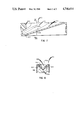
- FIG. 7 is a section view similar to that of FIG. 3, except it illustrates yet another embodiment.
- FIG. 8 is a section view taken generally along the line VIII--VIII of FIG. 7.
- the device of the invention is described in connection with the preferred embodiments, wherein a swab is used as the collecting means for collecting specimen from a patient, and extracted material is aspirated by a pipette.
- the device of the invention is useful with other similar collectors, such as a dip stick having absorbent pads at one end thereof. It is also useful with aspirators besides pipettes.
- the invention is to the extracting device, rather than to any particular form of collecting means used to place the specimen into the device for extraction, or to a particular aspirator used to remove the liquid used in the extraction.
- top refers to portions of the device as it is oriented in its position of use.
- an extraction device constructed in accord with the invention comprises a container 10 having supporting legs 12, 14 and 16, FIG. 1.
- the container has a top surface 18.
- a major cavity 20 is molded into the container, as formed by internal surface 22.
- Cavity 20 provides the confinement of the extracting liquid medium, and is shaped with a deep end 24, FIG. 3, that is generally at an end of container 10 opposite to the leg 14 and provides an additional leg of support.
- the bottom extent of cavity 20 is indicated by edge 26, FIG. 3.
- Top surface 18 limits the extent of cavity 20 and its contents.
- cavity 20 slopes downwardly, generally right to left, as measured at its bottom surface 26.
- the volume of cavity 20 is variable, depending on how large is container 10. Most preferably, however, that volume is kept small to reduce the dilution effect.
- a useful example of such volume of cavity 20 by itself, is about 0.8 ml.
- Notch 30 has a bottom surface 32 that is inclined at an angle alpha with respect to top surface 18. Angle alpha can vary generally from about 2° to about 60°, and most preferably is about 16°.
- Notch 30 and bottom surface 32 thereof are an extension of cavity 20, since both are formed by the same molded, internal surface 22.
- notch 30 contributes to the volume of cavity 20, for example, about 0.2 ml.
- the total volume of cavity 20 and notch 30 is about 1.0 ml.
- surface 22 is optionally provided with protruding lips 40, 42 adjacent top surface 18, on each side of the notch.
- the distance d, FIG. 2, between lips 40, 42 is such that a swab can be snapped into notch 30, and then forcibly pulled therefrom.
- "d" can be about 1.5 mm.
- centering surface 50 is provided in internal surface 22, adjacent deep end 24.
- Such centering surface is shaped with an internal radius r 1 at top surface 18 that is larger than the internal radius r 2 located further into cavity 20.
- the orientation of surface 50 is generally vertical, that is, about an axis 56 that extends at an angle beta to top surface 18. Most preferably, beta is generally about 90°.
- Axis 56 is also the centering line for insertion of pipette P into the device to aspirate up the liquid medium used for extraction.
- surface 50 is shaped to generally center and support the pipette P for aspiration of the extracting liquid.
- a swab is disposed within notch 30 with the absorbent end at deep end 24 of cavity 20.
- An appropriate extracting medium is poured into cavity 20, and allowed to act on the swab.
- Such liquids are conventional and need no further description.
- swab S is reciprocated and rotated along notch 30, towards and away from deep end 24, as a means for agitating the extracting liquid and to encourage the extraction of the biological material.
- a pipette P of any suitable construction is inserted along axis 56 down on top of the absorbent end of the swab (shown in phantom, FIG. 3).
- the angle between the positioning of swab S and the positioning of pipette P an axis 56 is (beta-alpha).
- container 10a has a cavity 20a generally constructed as in the previous embodiment, with an internal surface 22a and a deep end 24a, FIG. 5.
- notch 30a for swab S instead of extending below cavity 20a, is provided in a portion 100 rising vertically above the limiting surface 18a that defines the top of cavity 20a.
- notch 30a extends at an angle alpha' to surface 18a that is generally 90°. Notch 30a is also preferably enlarged at deep end 24a, to accommodate the absorbent end of the swab. Lips 40a and 42a are provided as in the previous embodiment.
- centering surface 50a that extends below the bottom extreme edge 26a of cavity 20a, FIG. 5. That surface provides a centering axis 56a that is inclined to surface 18a at an angle beta', which has a value between about 2° and 60°, and preferably about 16°. Centering surface 50a preferably terminates at a stop 110 that locates the aperture of pipette P adjacent swab S, FIG. 6.
- Antisplash features are optionally included in internal surface 22, as shown in FIGS. 7 and 8. Parts similar to those previously described bear the same reference numeral to which the distinguishing suffix "b" is added.
- container 10b has a cavity 20b, notch 30b, and centering surface 50b, all substantially identical to that described in the embodiment of FIGS. 1-3.
- internal surface 22b has been folded outwardly at 200 to provide two grooves, each on opposite sides of notch 30. These grooves act to damp out any splashing that might occur when swab S is pushed back and forth along notch 30b. Most preferably they extend generally parallel to bottom edge 26b of cavity 20b.
- Useful materials for the device of the invention include molded plastic, for example, polyethylene, polypropylene and the like.
Abstract
Description
Claims (8)
Priority Applications (4)
| Application Number | Priority Date | Filing Date | Title |
|---|---|---|---|
| US07/098,247 US4746614A (en) | 1987-09-18 | 1987-09-18 | Extraction device |
| CA000563371A CA1319311C (en) | 1987-09-18 | 1988-04-06 | Extraction device |
| EP88308557A EP0308230A3 (en) | 1987-09-18 | 1988-09-16 | Extraction device |
| JP63232141A JPH01120276A (en) | 1987-09-18 | 1988-09-16 | Extractor |
Applications Claiming Priority (1)
| Application Number | Priority Date | Filing Date | Title |
|---|---|---|---|
| US07/098,247 US4746614A (en) | 1987-09-18 | 1987-09-18 | Extraction device |
Publications (1)
| Publication Number | Publication Date |
|---|---|
| US4746614A true US4746614A (en) | 1988-05-24 |
Family
ID=22268339
Family Applications (1)
| Application Number | Title | Priority Date | Filing Date |
|---|---|---|---|
| US07/098,247 Expired - Fee Related US4746614A (en) | 1987-09-18 | 1987-09-18 | Extraction device |
Country Status (4)
| Country | Link |
|---|---|
| US (1) | US4746614A (en) |
| EP (1) | EP0308230A3 (en) |
| JP (1) | JPH01120276A (en) |
| CA (1) | CA1319311C (en) |
Cited By (15)
| Publication number | Priority date | Publication date | Assignee | Title |
|---|---|---|---|---|
| EP0363110A2 (en) * | 1988-10-07 | 1990-04-11 | Johnson & Johnson Clinical Diagnostics, Inc. | High pH extraction composition and its use to determine a chlamydial, gonococcal or herpes antigen |
| EP0363106A2 (en) * | 1988-10-07 | 1990-04-11 | Johnson & Johnson Clinical Diagnostics, Inc. | Use of cationic surfactant to extract the chlamydial major outer membrane protein antigen |
| EP0363105A2 (en) * | 1988-10-07 | 1990-04-11 | Johnson & Johnson Clinical Diagnostics, Inc. | Stabilized extraction composition containing a sulfhydryl-containing reducing agent and its use in chlamydial and gonococcal determination |
| EP0363089A2 (en) * | 1988-10-07 | 1990-04-11 | Johnson & Johnson Clinical Diagnostics, Inc. | Use of a protease in the extraction of chlamydial, gonococcal and herpes antigens |
| EP0382519A2 (en) * | 1989-02-09 | 1990-08-16 | Eastman Kodak Company | Extraction composition, test kit and their use to extract or determine herpes simplex viral antigen |
| US4963325A (en) * | 1988-05-06 | 1990-10-16 | Hygeia Sciences, Inc. | Swab expressor immunoassay device |
| US5120503A (en) * | 1989-07-14 | 1992-06-09 | Eastman Kodak Company | Extracting device for extracting antigens |
| US5392909A (en) * | 1993-11-03 | 1995-02-28 | Linvatec Corporation | Releasable universal blister package for elongated surgical devices |
| US5660273A (en) * | 1994-07-13 | 1997-08-26 | Centrix, Inc. | Single patient dose medicament dispenser with applicator |
| US5690222A (en) * | 1995-04-07 | 1997-11-25 | Linvatec Corporation | Package retainer for surgical screw |
| US6328159B1 (en) | 1994-07-13 | 2001-12-11 | Centrix, Inc | Single patient dose medicament dispenser with applicator |
| US6372816B1 (en) | 1999-06-25 | 2002-04-16 | Dentsply Detrey Gmbh | Dental materials packaging and method of use |
| US6685013B2 (en) | 1994-07-13 | 2004-02-03 | Centrix, Inc. | Single patient dose medicament dispenser with applicator |
| US20050255425A1 (en) * | 2000-09-21 | 2005-11-17 | Pierson Paul R | Mixing tip for dental materials |
| US8474337B2 (en) | 2010-03-31 | 2013-07-02 | Fujifilm Corporation | Extraction method, extraction vessel for use with the same, extraction kit and valve expansion member |
Citations (5)
| Publication number | Priority date | Publication date | Assignee | Title |
|---|---|---|---|---|
| US3116828A (en) * | 1961-08-30 | 1964-01-07 | Jacob A Glassman | Surgical instrucment trays |
| US4014746A (en) * | 1973-05-08 | 1977-03-29 | U.S. Medical Research And Development, Inc. | Method of and apparatus for collecting cultures |
| US4014748A (en) * | 1975-12-22 | 1977-03-29 | Marion Laboratories, Inc. | Anaerobic culture collecting and transporting apparatus |
| US4153160A (en) * | 1978-01-30 | 1979-05-08 | Johannah Medical Services, Inc. | Disposable slide-step percutaneous transhepatic cholangiography procedure tray |
| US4618576A (en) * | 1984-02-27 | 1986-10-21 | Becton Dickinson And Company | Diagnostic test for Streptococcus A |
Family Cites Families (2)
| Publication number | Priority date | Publication date | Assignee | Title |
|---|---|---|---|---|
| DE3220139A1 (en) * | 1982-05-28 | 1983-12-01 | Merck Patent Gmbh, 6100 Darmstadt | COLLECTING AND TRANSPORTATION DEVICE FOR MICROORGANISMS |
| FR2540513A1 (en) * | 1983-02-09 | 1984-08-10 | Schmorak Raymond | Device for preserving and transporting a bacterial sample |
-
1987
- 1987-09-18 US US07/098,247 patent/US4746614A/en not_active Expired - Fee Related
-
1988
- 1988-04-06 CA CA000563371A patent/CA1319311C/en not_active Expired - Fee Related
- 1988-09-16 EP EP88308557A patent/EP0308230A3/en not_active Ceased
- 1988-09-16 JP JP63232141A patent/JPH01120276A/en active Pending
Patent Citations (5)
| Publication number | Priority date | Publication date | Assignee | Title |
|---|---|---|---|---|
| US3116828A (en) * | 1961-08-30 | 1964-01-07 | Jacob A Glassman | Surgical instrucment trays |
| US4014746A (en) * | 1973-05-08 | 1977-03-29 | U.S. Medical Research And Development, Inc. | Method of and apparatus for collecting cultures |
| US4014748A (en) * | 1975-12-22 | 1977-03-29 | Marion Laboratories, Inc. | Anaerobic culture collecting and transporting apparatus |
| US4153160A (en) * | 1978-01-30 | 1979-05-08 | Johannah Medical Services, Inc. | Disposable slide-step percutaneous transhepatic cholangiography procedure tray |
| US4618576A (en) * | 1984-02-27 | 1986-10-21 | Becton Dickinson And Company | Diagnostic test for Streptococcus A |
Cited By (27)
| Publication number | Priority date | Publication date | Assignee | Title |
|---|---|---|---|---|
| US4963325A (en) * | 1988-05-06 | 1990-10-16 | Hygeia Sciences, Inc. | Swab expressor immunoassay device |
| EP0363110A2 (en) * | 1988-10-07 | 1990-04-11 | Johnson & Johnson Clinical Diagnostics, Inc. | High pH extraction composition and its use to determine a chlamydial, gonococcal or herpes antigen |
| EP0363106A2 (en) * | 1988-10-07 | 1990-04-11 | Johnson & Johnson Clinical Diagnostics, Inc. | Use of cationic surfactant to extract the chlamydial major outer membrane protein antigen |
| EP0363105A2 (en) * | 1988-10-07 | 1990-04-11 | Johnson & Johnson Clinical Diagnostics, Inc. | Stabilized extraction composition containing a sulfhydryl-containing reducing agent and its use in chlamydial and gonococcal determination |
| EP0363089A2 (en) * | 1988-10-07 | 1990-04-11 | Johnson & Johnson Clinical Diagnostics, Inc. | Use of a protease in the extraction of chlamydial, gonococcal and herpes antigens |
| EP0363089A3 (en) * | 1988-10-07 | 1991-07-10 | Johnson & Johnson Clinical Diagnostics, Inc. | Use of a protease in the extraction of chlamydial, gonococcal and herpes antigens |
| EP0363110A3 (en) * | 1988-10-07 | 1991-07-17 | Johnson & Johnson Clinical Diagnostics, Inc. | High ph extraction composition and its use to determine a chlamydial, gonococcal or herpes antigen |
| EP0363105A3 (en) * | 1988-10-07 | 1991-07-17 | Johnson & Johnson Clinical Diagnostics, Inc. | Stabilized extraction composition containing a sulfhydryl-containing reducing agent and its use in chlamydial and gonococcal determination |
| EP0363106A3 (en) * | 1988-10-07 | 1991-07-17 | Johnson & Johnson Clinical Diagnostics, Inc. | Use of cationic surfactant to extract the chlamydial major outer membrane protein antigen |
| EP0382519A2 (en) * | 1989-02-09 | 1990-08-16 | Eastman Kodak Company | Extraction composition, test kit and their use to extract or determine herpes simplex viral antigen |
| EP0382519A3 (en) * | 1989-02-09 | 1991-03-20 | Eastman Kodak Company | Extraction composition, test kit and their use to extract or determine herpes simplex viral antigen |
| US5120503A (en) * | 1989-07-14 | 1992-06-09 | Eastman Kodak Company | Extracting device for extracting antigens |
| US5392909A (en) * | 1993-11-03 | 1995-02-28 | Linvatec Corporation | Releasable universal blister package for elongated surgical devices |
| US20040134815A1 (en) * | 1994-07-13 | 2004-07-15 | Discko John J. | Single patient dose medicament dispenser with applicator |
| US20080035495A1 (en) * | 1994-07-13 | 2008-02-14 | Centrix, Inc. | Single patient dose medicament dispenser with applicator |
| US6116414A (en) * | 1994-07-13 | 2000-09-12 | Centrix, Inc. | Single patient dose medicament dispenser with applicator |
| US6328159B1 (en) | 1994-07-13 | 2001-12-11 | Centrix, Inc | Single patient dose medicament dispenser with applicator |
| US6959808B2 (en) | 1994-07-13 | 2005-11-01 | Centrix, Inc. | Single patient dose medicament dispenser with applicator |
| US6685013B2 (en) | 1994-07-13 | 2004-02-03 | Centrix, Inc. | Single patient dose medicament dispenser with applicator |
| US5660273A (en) * | 1994-07-13 | 1997-08-26 | Centrix, Inc. | Single patient dose medicament dispenser with applicator |
| US7243789B2 (en) | 1994-07-13 | 2007-07-17 | Centrix, Inc. | Single patient dose medicament dispenser with applicator |
| US20050269219A1 (en) * | 1994-07-13 | 2005-12-08 | Discko John J Jr | Single patient dose medicament dispenser with applicator |
| US7828142B2 (en) | 1994-07-13 | 2010-11-09 | Centrix, Inc. | Single patient dose medicament dispenser with applicator |
| US5690222A (en) * | 1995-04-07 | 1997-11-25 | Linvatec Corporation | Package retainer for surgical screw |
| US6372816B1 (en) | 1999-06-25 | 2002-04-16 | Dentsply Detrey Gmbh | Dental materials packaging and method of use |
| US20050255425A1 (en) * | 2000-09-21 | 2005-11-17 | Pierson Paul R | Mixing tip for dental materials |
| US8474337B2 (en) | 2010-03-31 | 2013-07-02 | Fujifilm Corporation | Extraction method, extraction vessel for use with the same, extraction kit and valve expansion member |
Also Published As
| Publication number | Publication date |
|---|---|
| EP0308230A3 (en) | 1989-12-13 |
| CA1319311C (en) | 1993-06-22 |
| EP0308230A2 (en) | 1989-03-22 |
| JPH01120276A (en) | 1989-05-12 |
Similar Documents
| Publication | Publication Date | Title |
|---|---|---|
| US4746614A (en) | Extraction device | |
| US4789639A (en) | Liquid recovery device | |
| AU612108B2 (en) | A device for use in the handling of body fluids | |
| US5422273A (en) | Cell collection apparatus | |
| EP1284160B1 (en) | Liquid specimen collection system | |
| US5915583A (en) | Container | |
| EP1877771B1 (en) | Tumor screening system | |
| JPH05133854A (en) | Gravity aiding type collecting apparatus | |
| US4528187A (en) | Apparatus for collecting and microscopically examining a specimen | |
| US5312009A (en) | Liquid specimen collector with removable extraction device | |
| US4483616A (en) | Container for small quantities of liquids | |
| EP0089972A1 (en) | Faeces collection and concentration receiver | |
| DE69829531T2 (en) | Removal vasculature | |
| JPH0867B2 (en) | Inoculator and assembly | |
| US3937370A (en) | Controlled depth aspiration cannula | |
| US5952239A (en) | Cytology chamber with port to receive collection bottle and method of use | |
| US9339013B1 (en) | Urine collection device | |
| EP0084557A1 (en) | Container for small quantities of liquids | |
| JPH0742133Y2 (en) | Sediment smear container for clinical examination | |
| US20210394191A1 (en) | Universal stand for holding capillary and transfer pipettes | |
| CN220512042U (en) | Disposable biopsy specimen position fixing and preserving device | |
| JP2538518B2 (en) | Centrifugal test tube for urine sediment | |
| JPH0663136U (en) | Test tube | |
| KR200302951Y1 (en) | Pipette for long type yellow tip | |
| JPH0112177Y2 (en) |
Legal Events
| Date | Code | Title | Description |
|---|---|---|---|
| FEPP | Fee payment procedure |
Free format text: PAYOR NUMBER ASSIGNED (ORIGINAL EVENT CODE: ASPN); ENTITY STATUS OF PATENT OWNER: LARGE ENTITY |
|
| AS | Assignment |
Owner name: EASTMAN KODAK COMPANY, ROCHESTER, NEW YORK A NJ CO Free format text: ASSIGNMENT OF ASSIGNORS INTEREST.;ASSIGNORS:DEVANEY, MARK J. JR.;GLANVILLE, THOMAS W.;REEL/FRAME:004832/0060 Effective date: 19870916 |
|
| FPAY | Fee payment |
Year of fee payment: 4 |
|
| FEPP | Fee payment procedure |
Free format text: PAYER NUMBER DE-ASSIGNED (ORIGINAL EVENT CODE: RMPN); ENTITY STATUS OF PATENT OWNER: LARGE ENTITY Free format text: PAYOR NUMBER ASSIGNED (ORIGINAL EVENT CODE: ASPN); ENTITY STATUS OF PATENT OWNER: LARGE ENTITY |
|
| AS | Assignment |
Owner name: CLINICAL DIAGNOSTIC SYSTEMS INC., NEW YORK Free format text: ASSIGNMENT OF ASSIGNORS INTEREST;ASSIGNOR:EASTMAN KODAK COMPANY;REEL/FRAME:007453/0348 Effective date: 19950118 |
|
| FPAY | Fee payment |
Year of fee payment: 8 |
|
| REMI | Maintenance fee reminder mailed | ||
| LAPS | Lapse for failure to pay maintenance fees | ||
| FP | Lapsed due to failure to pay maintenance fee |
Effective date: 20000524 |
|
| STCH | Information on status: patent discontinuation |
Free format text: PATENT EXPIRED DUE TO NONPAYMENT OF MAINTENANCE FEES UNDER 37 CFR 1.362 |